TECHNICAL & SERVICE MANUAL DC INVERTER MULTI-SYSTEM ...
TECHNICAL & SERVICE MANUAL DC INVERTER MULTI-SYSTEM ...
TECHNICAL & SERVICE MANUAL DC INVERTER MULTI-SYSTEM ...

Create successful ePaper yourself
Turn your PDF publications into a flip-book with our unique Google optimized e-Paper software.
1. OPERATING RANGECoolingHeatingTemperature Indoor Air Intake Temp. Outdoor Air Intake Temp.MaximumMinimumMaximumMinimum32 °C D.B. / 23 °C W.B.19 °C D.B. / 14 °C W.B.27 °C D.B.16 °C D.B.43 °C D.B.19 °C D.B.24 °C D.B. / 18 °C W.B._ D.B. / -15 °C W.B.6
Outdoor Unit AE3MI68AHIndoor Unit AWMI27AHL × 3TypeNumber of Connectable Indoor UnitsNumber of Operatable Indoor UnitsMax. Capacity of Operating Indoor UnitsPower SourceVoltage RatingkW4-Room Multi Outdoor Unit4312.2220 to 240V Single-Phase 50Hz230VPerformanceCapacityAir Circulation (High)kWBTU/hm 3 /h6.823,200Cooling( 2.9 to 8.1 )( 9,900 to 27,600 )2,9008.629,300Heating( 3.4 to 9.0 )( 11,600 to 30,700 )2,900Electrical RatingCoolingAvailable Voltage RangeV198 to 264Running AmperesPower InputAW8.872,000Power Factor %98E.E.R. W/W 3.40C.O.P.W/W -Compressor Locked Rotor Amperes A 14.5Heating8.872,00098-4.30Features (Outdoor Unit)ControlMicroprocessorFan SpeedsAuto (Hi, Me, Lo)CompressorRefrigerant / Amount charged at shipmentkg<strong>DC</strong> Twin Rotary (Inverter)R410A / 2.8Refrigerant ControlElectric Expansion ValveOperation Sound Hi dB-A50 52Refrigerant Tubing ConnectionsFlare TypeMax. allowable tubing length per unitm25RefrigerantNarrow tubemm (in.)6.35 (1/4") × 4Tube Diameter Wide tubemm (in.)9.52 (3/8") × 3 + 12.7 (1/2") × 1Dimensions & Weight (Outdoor Unit)Unit DimensionsPackage DimensionsWeightHeight × Width × DepthHeight × Width × DepthShipping VolumeNetShippingmmmmkgkgm 3740 × 900 × 320868 × 1,050 × 42365.069.00.38DATA SUBJECT TO CHANGE WITHOUT NOTICE.Remarks:1. The Values shown in performance section and electrical rating section above are based on the following unit combination.For other combination unit, please refer to the "Unit Combination Tables" in this manual.Indoor Unit : AWMI27AHL 3units Outdoor Unit : AE3MI68AH 1unit2. Rating conditions are: Cooling : Indoor air temp. 27°C D.B. / 19°C W.B. Heating : Indoor air temp. 20°C D.B.Outdoor air temp. 35°C D.B. / 24°C W.B.Outdoor air temp. 7°C D.B. / 6°C W.B.9
Outdoor Unit AE4MI80AHIndoor Unit AWMI27AHL × 4TypeNumber of Connectable Indoor UnitsNumber of Operatable Indoor UnitsMax. Capacity of Operating Indoor UnitsPower SourceVoltage RatingkW4-Room Multi Outdoor Unit4414.7220 to 240V Single-Phase 50Hz230VPerformanceCapacityAir Circulation (High)kWBTU/hm 3 /h8.027,300Cooling( 2.9 to 9.2 )( 9,900 to 31,400 )3,0709.432,100Heating( 3.4 to 9.8 )( 11,600 to 33,400 )3,070Electrical RatingCoolingAvailable Voltage RangeV198 to 264Running AmperesPower InputAW7.581,725Power Factor %99E.E.R. W/W 4.64C.O.P.W/W -Compressor Locked Rotor Amperes A 17.0Heating8.962,04099-4.61Features (Outdoor Unit)ControlMicroprocessorFan SpeedsAuto (Hi, Me, Lo)CompressorRefrigerant / Amount charged at shipmentkg<strong>DC</strong> Twin Rotary (Inverter)R410A / 3.8Refrigerant ControlElectric Expansion ValveOperation Sound Hi dB-A50 52Refrigerant Tubing ConnectionsFlare TypeMax. allowable tubing length per unitm30RefrigerantNarrow tubemm (in.)6.35 (1/4") × 4Tube Diameter Wide tubemm (in.)9.52 (3/8") × 2 + 12.7 (1/2") × 2Dimensions & Weight (Outdoor Unit)Unit DimensionsPackage DimensionsWeightHeight × Width × DepthHeight × Width × DepthShipping VolumeNetShippingmmmmkgkgm 3890 × 900 × 3201,019 × 1,050 × 42382.086.00.45DATA SUBJECT TO CHANGE WITHOUT NOTICE.Remarks:1. The Values shown in performance section and electrical rating section above are based on the following unit combination.For other combination unit, please refer to the "Unit Combination Tables" in this manual.Indoor Unit : AWMI27AHL 4units Outdoor Unit : AE4MI80AH 1unit2. Rating conditions are: Cooling : Indoor air temp. 27°C D.B. / 19°C W.B. Heating : Indoor air temp. 20°C D.B.Outdoor air temp. 35°C D.B. / 24°C W.B.Outdoor air temp. 7°C D.B. / 6°C W.B.10
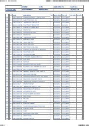
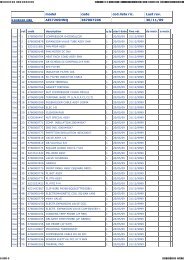
2-2. Major Component Specifications2-2-1. Outdoor UnitOutdoor UnitAE2MI40AHControl PCBPart No.ControlsControl Circuit FuseCB-CMRV1424EHMicroprocessor250V 25ACompressorTypeCompressor Model / Nominal OutputCompressor Oil ... AmountCoil Resistance (Ambient Temp. 20 °C)ccOhmSafety DeviceCT (Peak current cut-off control)Compressor Discharge Temp. ControlOperation cut-off control in abnormal ambient Temp.Overload RelayModelRun CapacitorCrankcase Heater<strong>DC</strong> Twin Rotary (Hermetic)C-6RVN93H0M / 1,000WFV50S ... 350R - S : 0.482S - T : 0.482T - R : 0.482YesYesYesCS-7L115Operation Temp. Open : 115 °C, Close : 95 °CMicro F-VAC--FanTypeQ'ty ... Dia.mmPropeller1 ... D420Fan MotorTypeModel ... Q'tyNo. of PolesRough Measure RPM (Cool:Hi / Heat:Hi)Nominal OutputCoil Resistance(Ambient Temp. 20 °C)Safety DeviceTypeOver-Current ProtectionRun CapacitorWOhmMicro FVAC<strong>DC</strong> MotorDAJ12-55J71-CR ... 18750 / 75050RED - WHT : 77.5WHT - BLU : 77.5BLU - RED : 77.5Internal ControllerYes--Heat Exchanger CoilCoilRowsFin PitchmmFace Area m 2External FinishAluminum Plate Fin / Copper Tube2130.452Acrylic baked-on enamel finishDATA SUBJECT TO CHANGE WITHOUT NOTICE.11
Outdoor UnitAE2MI56AHBControl PCBPart No.ControlsControl Circuit FuseCB-CMRV1924EHMicroprocessor250V 25ACompressorTypeCompressor Model / Nominal OutputCompressor Oil ... AmountCoil Resistance (Ambient Temp. 20 °C)Safety DeviceCT (Peak current cut-off control)Compressor Discharge Temp. ControlOperation cut-off control in abnormal ambient Temp.Overload RelayModelRun CapacitorCrankcase Heater<strong>DC</strong> Twin Rotary (Hermetic)5KD240XAB21 / 1,700Wcc FV50S ... 900OhmU - V : 0.720V - W : 0.708W - U : 0.726YesYesYesCS-7LN115Operation Temp. Open : 115 °C, Close : 100 °CMicro F-VAC-230V 25WFanTypeQ'ty ... Dia.mmPropeller1 ... D460Fan MotorTypeModel ... Q'tyNo. of PolesRough Measure RPM (Cool:Hi / Heat:Hi)Nominal OutputCoil Resistance(Ambient Temp. 20 °C)Safety DeviceTypeOver-Current ProtectionOver-Heat ProtectionRun CapacitorWOhmMicro FVAC<strong>DC</strong> MotorSIC-71FW-D490-1 ... 18750 / 75090-Internal ControllerYesYes--Heat Exchanger CoilCoilRowsFin PitchmmAluminum Plate Fin / Copper Tube21.4Face Area 0.595m 2External FinishAcrylic baked-on enamel finishDATA SUBJECT TO CHANGE WITHOUT NOTICE.12
Outdoor UnitAE3MI68AHControl PCBPart No.ControlsControl Circuit FuseCB-CMRV2444EHMicroprocessor250V 25ACompressorTypeCompressor Model / Nominal OutputCompressor Oil ... AmountCoil Resistance (Ambient Temp. 20 °C)Safety DeviceCT (Peak current cut-off control)Compressor Discharge Temp. ControlOperation cut-off control in abnormal ambient Temp.Overload RelayModelRun CapacitorCrankcase Heater<strong>DC</strong> Twin Rotary (Hermetic)5KD240XAB21 / 1,700Wcc FV50S ... 900OhmU - V : 0.720V - W : 0.708W - U : 0.726YesYesYesCS-7LN115Operation Temp. Open : 115 °C, Close : 100 °CMicro F-VAC-230V 25WFanTypeQ'ty ... Dia.mmPropeller1 ... D460Fan MotorTypeModel ... Q'tyNo. of PolesRough Measure RPM (Cool:Hi / Heat:Hi)Nominal OutputCoil Resistance(Ambient Temp. 20 °C)Safety DeviceTypeOver-Current ProtectionOver-Heat ProtectionRun CapacitorWOhmMicro FVAC<strong>DC</strong> MotorSIC-71FW-D490-1 ... 18750 / 75090-Internal ControllerYesYes--Heat Exchanger CoilCoilRowsFin PitchmmAluminum Plate Fin / Copper Tube21.4Face Area 0.595m 2External FinishAcrylic baked-on enamel finishDATA SUBJECT TO CHANGE WITHOUT NOTICE.13
Outdoor UnitAE4MI80AHControl PCBPart No.ControlsControl Circuit FuseCB-CMRV3144EHMicroprocessor250V 25ACompressorTypeCompressor Model / Nominal OutputCompressor Oil ... AmountCoil Resistance (Ambient Temp. 20 °C)Safety DeviceCT (Peak current cut-off control)Compressor Discharge Temp. ControlOperation cut-off control in abnormal ambient Temp.Overload RelayModelRun CapacitorCrankcase Heater<strong>DC</strong> Twin Rotary (Hermetic)5JD420XAB22 / 3,000Wcc FV50S ... 1,200OhmU - V : 0.435V - W : 0.441W - U : 0.452YesYesYesCS-7LN115Operation Temp. Open : 115 °C, Close : 100 °CMicro F-VAC-230V 25WFanTypeQ'ty ... Dia.mmPropeller1 ... D460Fan MotorTypeModel ... Q'tyNo. of PolesRough Measure RPM (Cool:Hi / Heat:Hi)Nominal OutputCoil Resistance(Ambient Temp. 20 °C)Safety DeviceTypeOver-Current ProtectionOver-Heat ProtectionRun CapacitorWOhmMicro FVAC<strong>DC</strong> MotorSIC-71FW-D490-1 ... 18750 / 75090-Internal ControllerYesYes--Heat Exchanger CoilCoilRowsFin PitchmmAluminum Plate Fin / Copper Tube21.4Face Area 0.723m 2External FinishAcrylic baked-on enamel finishDATA SUBJECT TO CHANGE WITHOUT NOTICE.14
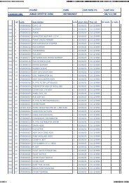
2-3. Other Component SpecificationsSensor NameModel No.of sensorQuantity of SensorAE2MI40AH AE2MI56AHB AE3MI68AH AE4MI80AHOutdoor air temp sensorTKS295B1111Outdoor heat exchanger sensorTKS292B1111AW / AN sensorTKS292B1/11/11/11/1BW / BN sensorTKS292B1/11/11/11/1CW / CN sensorTKS292B001/11/1DW / DN sensorTKS292B001/11/140Resistance (k ohm)35302520151050-20 -15 -10 -5 0 5 10 15 20Temperature (°C)Sensor NameModel No.of sensorQuantity of SensorAE2MI40AH AE2MI56AHB AE3MI68AH AE4MI80AHCompressor temp sensorTKS293B1 11 1Resistance (k ohm)2001801601401201008060402000 10 20 30 40 50 60 70 80 90Temperature (°C)15
3. DIMENSIONAL DATAOutdoor Unit AE2MI40AH608 852-ID:124-ID:23.629528531033646ID:18Narrow tube service valvedia.6.35 (1/4") × 2790 70Wide tube service valvedia.9.52 (3/8") × 2158 70151227056946142Unit: mm16
Outdoor Unit AE2MI56AHB608 13635293ID:185-ID:23.612320345369Narrow tube service valvedia.6.35 (1/4") × 2900 85Wide tube service valvedia.9.52 (3/8") × 218150 721137574051114Unit: mm17
Outdoor Unit AE3MI68AH608 13635293ID:185-ID:23.612320345369Wide tube service valvedia.12.70 (1/2") × 1Narrow tube service valvedia.6.35 (1/4") × 4900 85Wide tube service valvedia.9.52 (3/8") × 318740150 72 707011375 707051114Unit: mm18
Outdoor Unit AE4MI80AH608 13635293ID:185-ID:23.612320345369Wide tube service valvedia.12.70 (1/2") × 2Narrow tube service valvedia.6.35 (1/4") × 4900 85Wide tube service valvedia.9.52 (3/8") × 218150 73 707011375 707089051114Unit: mm19
4. REFRIGERANT FLOW DIAGRAM4-1. Refrigerant Flow DiagramOutdoor Unit AE2MI40AHIndoor unitOutdoor unitWide tubeO.D.9.52mmO.D.9.52mmService valve onwide tubeBWAWMufflerSubaccumulatorMainaccumulatorCompressor4-wayvalveDefrost valvefor hot gas bypassSHeat exchangerNarrow tubeO.D.6.35mmO.D.6.35mmService valve onnarrow tubeBNANStrainerElectricexpansionvalveMMCapillarytube forsplit flowCooling cycleHeating cycleDefrosting cycleInsulation of Refrigerant TubingIMPORTANTBecause capillary tubing is used in the outdoor unit, both thewide and narrow tubes of this air conditioner become cold. Toprevent heat loss and wet floors due to dripping ofcondensation, both tubes must be well insulated with aproper insulation material. The thickness of the insulationshould be a min. 8 mm.Thickness:Min. 8 mmInsulationThickness:Min. 8 mmCAUTIONAfter a tube has been insulated,never try to bend it into a narrowcurve because it can cause the tubeto break or crack.Wide tubeNarrow tube20
Outdoor UnitAE2MI56AHBIndoor unitOutdoor unitWide tubeO.D.9.52mmO.D.9.52mmService valve onwide tubeBWAWHeaderSubaccumulatorMainaccumulatorCompressor4-wayvalveDefrost valvefor hot gas bypassSHeat exchangerNarrow tubeO.D.6.35mmO.D.6.35mmService valve onnarrow tubeBNANStrainerElectricexpansionvalveMMHeaderCooling cycleHeating cycleDefrosting cycleInsulation of Refrigerant TubingIMPORTANTBecause capillary tubing is used in the outdoor unit, both thewide and narrow tubes of this air conditioner become cold. Toprevent heat loss and wet floors due to dripping ofcondensation, both tubes must be well insulated with aproper insulation material. The thickness of the insulationshould be a min. 8 mm.Thickness:Min. 8 mmInsulationThickness:Min. 8 mmCAUTIONAfter a tube has been insulated,never try to bend it into a narrowcurve because it can cause the tubeto break or crack.Wide tubeNarrow tube21
Outdoor UnitAE3MI68AHIndoor unitOutdoor unitWide tubeO.D.9.52mmO.D.9.52mmO.D.9.52mmO.D.12.7mmService valve onwide tubeDWCWBWAWHeader4-wayvalveSubaccumulatorMainaccumulatorCompressorNarrow tubeO.D.6.35mmO.D.6.35mmO.D.6.35mmO.D.6.35mmService valve onnarrow tubeDNCNBNANStrainerElectricexpansionvalveMMMMHeaderDefrost valvefor hot gas bypassSHeat exchangerCooling cycleHeating cycleDefrosting cycleInsulation of Refrigerant TubingIMPORTANTBecause capillary tubing is used in the outdoor unit, both thewide and narrow tubes of this air conditioner become cold. Toprevent heat loss and wet floors due to dripping ofcondensation, both tubes must be well insulated with aproper insulation material. The thickness of the insulationshould be a min. 8 mm.Thickness:Min. 8 mmInsulationThickness:Min. 8 mmCAUTIONAfter a tube has been insulated,never try to bend it into a narrowcurve because it can cause the tubeto break or crack.Wide tubeNarrow tube22
Outdoor UnitAE4MI80AHIndoor unitOutdoor unitWide tubeO.D.9.52mmO.D.9.52mmO.D.12.7mmO.D.12.7mmService valve onwide tubeDWCWBWAWHeader4-wayvalveSubaccumulatorMainaccumulatorCompressorNarrow tubeO.D.6.35mmO.D.6.35mmO.D.6.35mmO.D.6.35mmService valve onnarrow tubeDNCNBNANStrainerElectricexpansionvalveMMMMHeaderDefrost valvefor hot gas bypassSHeat exchangerCooling cycleHeating cycleDefrosting cycleInsulation of Refrigerant TubingIMPORTANTBecause capillary tubing is used in the outdoor unit, both thewide and narrow tubes of this air conditioner become cold. Toprevent heat loss and wet floors due to dripping ofcondensation, both tubes must be well insulated with aproper insulation material. The thickness of the insulationshould be a min. 8 mm.Thickness:Min. 8 mmInsulationThickness:Min. 8 mmCAUTIONAfter a tube has been insulated,never try to bend it into a narrowcurve because it can cause the tubeto break or crack.Wide tubeNarrow tube23
5. PERFORMANCE DATA5-1. Temperature Charts5-1-1. Temperature Charts (AE2MI40AH)Outdoor Unit AE2MI40AH Indoor Unit AWMI22AHL × 1Cooling Characteristics(RH : 46%, Indoor fan speed : High fan)(230V, 50Hz)Heating Characteristics(RH : 85%, Indoor fan speed : High fan)(230V, 50Hz)(1) Low pressure performance chart (1) High pressure performance chartLow pressure at wide tube service valveMPaG (kgf/cm 2 G)1.6(16.2)1.4(14.2)1.2(12.2)Lo fanHi fanIndoor air temp.30°C27°C24°C1.0(10.2) 1.525 30 35 40(15.3) -5 0 5 10 15 20 25Outdoor air temperature (°C)(2) Operating current performance chart (2) Operating current performance chartHigh pressure at wide tube service valveMPaG (kgf/cm 2 G)3.5(35.7)3.0(30.6)2.5(25.5)2.0(20.4)Indoor air temp.23°C20°C17°COutdoor air temperature (°C)4Lo fanHi fan4Operating current (A)32Indoor air temp.30°C27°C24°COperating current (A)32Indoor air temp.23°C20°C17°C1 125 30 35 40-5 0 5 10 15 20 25Outdoor air temperature (°C)Outdoor air temperature (°C)(3) Indoor discharge air performance chart (3) Indoor discharge air performance chart2555Indoor discharge air temperature (°C)201510Lo fanHi fanIndoor air temp.30°C27°C24°CIndoor discharge air temperature (°C)504540353025Indoor air temp.23°C20°C17°C52530 35 4020-5 0 5 10 15 20 25Outdoor air temperature (°C)Outdoor air temperature (°C)NOTE• This performance chart shows operation of a single wall-mounted indoor unit. The performance chart will vary depending onthe indoor unit type.• Check each performance value in test-run mode. Electrical performance values represent a combined indoor/outdoor value.(In this case, be sure to stop all the indoor units where performance is not being checked.)• The performance is for a tubing length of 7.5 m. If the tubing length is different, the performance chart will vary.24
Outdoor Unit AE2MI40AH Indoor Unit AWMI27AHL × 1Cooling Characteristics(RH : 46%, Indoor fan speed : High fan)(230V, 50Hz)Heating Characteristics(RH : 85%, Indoor fan speed : High fan)(230V, 50Hz)(1) Low pressure performance chart (1) High pressure performance chartLow pressure at wide tube service valveMPaG (kgf/cm 2 G)1.6(16.2)1.4(14.2)1.2(12.2)1.0(10.2)25Lo fanHi fanIndoor air temp.30°C27°C24°C30 35 40High pressure at wide tube service valveMPaG (kgf/cm 2 G)3.5(35.7)3.0(30.6)2.5(25.5)Indoor air temp.23°C20°C17°C2.0(20.4)-5 0 5 10 15 20 25Outdoor air temperature (°C)Outdoor air temperature (°C)(2) Operating current performance chart (2) Operating current performance chartOperating current (A)4Lo fan Hi fan32Indoor air temp.30°C27°C24°C30 35 40Outdoor air temperature (°C)Operating current (A)7654Indoor air temp.23°C20°C17°C3-5 0 5 10 15 20 25Outdoor air temperature (°C)(3) Indoor discharge air performance chart (3) Indoor discharge air performance chart2560Indoor discharge air temperature (°C)201510Lo fanHi fanIndoor air temp.30°C27°C24°CIndoor discharge air temperature (°C)555045403530Indoor air temp.23°C20°C17°C52530 35 4025-5 0 5 10 15 20 25Outdoor air temperature (°C)Outdoor air temperature (°C)NOTE• This performance chart shows operation of a single wall-mounted indoor unit. The performance chart will vary depending onthe indoor unit type.• Check each performance value in test-run mode. Electrical performance values represent a combined indoor/outdoor value.(In this case, be sure to stop all the indoor units where performance is not being checked.)• The performance is for a tubing length of 7.5 m. If the tubing length is different, the performance chart will vary.25
Outdoor Unit AE2MI40AH Indoor Unit AWMI35AHL × 1Cooling Characteristics(RH : 46%, Indoor fan speed : High fan)(230V, 50Hz)Heating Characteristics(RH : 85%, Indoor fan speed : High fan)(230V, 50Hz)(1) Low pressure performance chart (1) High pressure performance chartLow pressure at wide tube service valveMPaG (kgf/cm 2 G)1.4(14.2)1.2(12.2)1.0(10.2)0.8(8.2)25Lo fanHi fanIndoor air temp.30°C27°C24°C30 35 40High pressure at wide tube service valveMPaG (kgf/cm 2 G)4.0(40.8)3.5(35.7)3.0(30.6)Indoor air temp.23°C20°C17°C2.5(25.5)-5 0 5 10 15 20 25Outdoor air temperature (°C)Outdoor air temperature (°C)(2) Operating current performance chart (2) Operating current performance chartOperating current (A)6Lo fan Hi fan54Indoor air temp.30°C27°C24°C30 35 40Outdoor air temperature (°C)Operating current (A)8765Indoor air temp.23°C20°C17°C4-5 0 5 10 15 20 25Outdoor air temperature (°C)(3) Indoor discharge air performance chart (3) Indoor discharge air performance chart2565Indoor discharge air temperature (°C)201510Lo fanHi fanIndoor air temp.30°C27°C24°CIndoor discharge air temperature (°C)605550454035Indoor air temp.23°C20°C17°C52530 35 4030-5 0 5 10 15 20 25Outdoor air temperature (°C)Outdoor air temperature (°C)NOTE• This performance chart shows operation of a single wall-mounted indoor unit. The performance chart will vary depending onthe indoor unit type.• Check each performance value in test-run mode. Electrical performance values represent a combined indoor/outdoor value.(In this case, be sure to stop all the indoor units where performance is not being checked.)• The performance is for a tubing length of 7.5 m. If the tubing length is different, the performance chart will vary.26
5-1-2. Temperature Charts (AE2MI56AHB)Outdoor Unit AE2MI56AHB Indoor Unit AWMI22AHL × 1Cooling Characteristics(RH : 46%, Indoor fan speed : High fan)(230V, 50Hz)Heating Characteristics(RH : 85%, Indoor fan speed : High fan)(230V, 50Hz)(1) Low pressure performance chart (1) High pressure performance chartLow pressure at wide tube service valveMPaG (kgf/cm 2 G)1.3(13.2)1.2(12.2)1.1(11.2)1.0(10.2)25Lo fan Hi fan HH fanIndoor air temp.30°C27°C24°C30 35 40High pressure at wide tube service valveMPaG (kgf/cm 2 G)3.5(35.7)3.0(30.6)2.5(25.5)Indoor air temp.23°C20°C17°C2.0(20.4) -5 0 5 10 15 20 25Outdoor air temperature (°C)Outdoor air temperature (°C)(2) Operating current performance chart (2) Operating current performance chartOperating current (A)Lo fan Hi fan HH fan543Indoor air temp.30°C27°C24°C30 35 40Outdoor air temperature (°C)Operating current (A)8765Indoor air temp.23°C20°C17°C-5 0 5 10 15 20 25Outdoor air temperature (°C)(3) Indoor discharge air performance chart (3) Indoor discharge air performance chart60Indoor discharge air temperature (°C)201816141210Lo fan Hi fan HH fanIndoor air temp.30°C27°C24°CIndoor discharge air temperature (°C)555045403530Indoor air temp.23°C20°C17°C82530 35 4025-5 0 5 10 15 20 25Outdoor air temperature (°C)Outdoor air temperature (°C)NOTE• This performance chart shows operation of a single wall-mounted indoor unit. The performance chart will vary depending onthe indoor unit type.• Check each performance value in test-run mode. Electrical performance values represent a combined indoor/outdoor value.(In this case, be sure to stop all the indoor units where performance is not being checked.)• The performance is for a tubing length of 7.5 m. If the tubing length is different, the performance chart will vary.27
Outdoor Unit AE2MI56AHB Indoor Unit AWMI27AHL × 1Cooling Characteristics(RH : 46%, Indoor fan speed : High fan)(230V, 50Hz)Heating Characteristics(RH : 85%, Indoor fan speed : High fan)(230V, 50Hz)(1) Low pressure performance chart (1) High pressure performance chartLow pressure at wide tube service valveMPaG (kgf/cm 2 G)1.3(13.2)1.2(12.2)1.1(11.2)1.0(10.2)25Lo fanHi fanIndoor air temp.30°C27°C24°CHH fan30 35 40High pressure at wide tube service valveMPaG (kgf/cm 2 G)3.5(35.7)3.0(30.6)2.5(25.5)Indoor air temp.23°C20°C17°C2.0(20.4)-5 0 5 10 15 20 25Outdoor air temperature (°C)Outdoor air temperature (°C)(2) Operating current performance chart (2) Operating current performance chartOperating current (A)Lo fan Hi fan654Indoor air temp.30°C27°C24°C30 35 40Outdoor air temperature (°C)HH fanOperating current (A)8765Indoor air temp.23°C20°C17°C-5 0 5 10 15 20 25Outdoor air temperature (°C)(3) Indoor discharge air performance chart (3) Indoor discharge air performance chart60Indoor discharge air temperature (°C)2018161412Lo fanHi fanIndoor air temp.30°C27°C24°CHH fanIndoor discharge air temperature (°C)555045403530Indoor air temp.23°C20°C17°C102530 35 4025-5 0 5 10 15 20 25Outdoor air temperature (°C)Outdoor air temperature (°C)NOTE• This performance chart shows operation of a single wall-mounted indoor unit. The performance chart will vary depending onthe indoor unit type.• Check each performance value in test-run mode. Electrical performance values represent a combined indoor/outdoor value.(In this case, be sure to stop all the indoor units where performance is not being checked.)• The performance is for a tubing length of 7.5 m. If the tubing length is different, the performance chart will vary.28
Outdoor Unit AE2MI56AHB Indoor Unit AWMI35AHL × 1Cooling Characteristics(RH : 46%, Indoor fan speed : High fan)(230V, 50Hz)Heating Characteristics(RH : 85%, Indoor fan speed : High fan)(230V, 50Hz)(1) Low pressure performance chart (1) High pressure performance chartLow pressure at wide tube service valveMPaG (kgf/cm 2 G)1.2(12.2)1.1(11.2)1.0(10.2)0.9(9.2)25Lo fanHi fanIndoor air temp.30°C27°C24°C30 35 40Outdoor air temperature (°C)HH fan-5 0 5 10 15 20 25Outdoor air temperature (°C)(2) Operating current performance chart (2) Operating current performance chartHigh pressure at wide tube service valveMPaG (kgf/cm 2 G)4.0(40.8)3.5(35.7)3.0(30.6)2.5(25.5)Indoor air temp.23°C20°C17°COperating current (A)Lo fan Hi fan654Indoor air temp.30°C27°C24°C30 35 40Outdoor air temperature (°C)HH fanOperating current (A)10987654Indoor air temp.23°C20°C17°C3-5 0 5 10 15 20 25Outdoor air temperature (°C)(3) Indoor discharge air performance chart (3) Indoor discharge air performance chart60Indoor discharge air temperature (°C)201816141210Lo fanHi fanIndoor air temp.30°C27°C24°CHH fanIndoor discharge air temperature (°C)55504540353020°CIndoor air temp.23°C17°C82530 35 4025-5 0 5 10 15 20 25Outdoor air temperature (°C)Outdoor air temperature (°C)NOTE• This performance chart shows operation of a single wall-mounted indoor unit. The performance chart will vary depending onthe indoor unit type.• Check each performance value in test-run mode. Electrical performance values represent a combined indoor/outdoor value.(In this case, be sure to stop all the indoor units where performance is not being checked.)• The performance is for a tubing length of 7.5 m. If the tubing length is different, the performance chart will vary.29
Outdoor Unit AE2MI56AHB Indoor Unit AWI52AHL × 1Cooling Characteristics(RH : 46%, Indoor fan speed : High fan)(230V, 50Hz)Heating Characteristics(RH : 85%, Indoor fan speed : High fan)(230V, 50Hz)(1) Low pressure performance chart (1) High pressure performance chartLow pressure at wide tube service valveMPaG (kgf/cm 2 G)1.2(12.2)1.1(11.2)1.0(10.2)0.9(9.2)25Lo fanHi fanIndoor air temp.30°C27°C24°CHH fan30 35 40High pressure at wide tube service valveMPaG (kgf/cm 2 G)4.0(40.8)3.5(35.7)3.0(30.6)Indoor air temp.23°C20°C17°C2.5(25.5) -5 0 5 10 15 20 25Outdoor air temperature (°C)Outdoor air temperature (°C)(2) Operating current performance chart (2) Operating current performance chart8Lo fanHi fanHH fan12Operating current (A)76Indoor air temp.30°C27°C24°COperating current (A)111098Indoor air temp.23°C20°C17°C572530 35 40Outdoor air temperature (°C)6-5 0 5 10 15 20 25Outdoor air temperature (°C)(3) Indoor discharge air performance chart (3) Indoor discharge air performance chartIndoor discharge air temperature (°C)201816141210Lo fanHi fanIndoor air temp.30°C27°C24°CHH fanIndoor discharge air temperature (°C)605550454035Indoor air temp.23°C20°C17°C82530 35 4030-5 0 5 10 15 20 25Outdoor air temperature (°C)Outdoor air temperature (°C)NOTE• This performance chart shows operation of a single wall-mounted indoor unit. The performance chart will vary depending onthe indoor unit type.• Check each performance value in test-run mode. Electrical performance values represent a combined indoor/outdoor value.(In this case, be sure to stop all the indoor units where performance is not being checked.)• The performance is for a tubing length of 7.5 m. If the tubing length is different, the performance chart will vary.30
5-1-3. Temperature Charts (AE3MI68AH)Outdoor Unit AE3MI68AH Indoor Unit AWMI22AHL × 1Cooling Characteristics(RH : 46%, Indoor fan speed : High fan)(230V, 50Hz)Heating Characteristics(RH : 85%, Indoor fan speed : High fan)(230V, 50Hz)(1) Low pressure performance chart (1) High pressure performance chartLow pressure at wide tube service valveMPaG (kgf/cm 2 G)1.3(13.2)1.2(12.2)1.1(11.2)1.0(10.2)25Lo fan Hi fan HH fanIndoor air temp.30°C27°C24°C30 35 40High pressure at wide tube service valveMPaG (kgf/cm 2 G)3.5(35.7)3.0(30.6)2.5(25.5)Indoor air temp.23°C20°C17°C2.0(20.4) -5 0 5 10 15 20 25Outdoor air temperature (°C)Outdoor air temperature (°C)(2) Operating current performance chart (2) Operating current performance chartOperating current (A)Lo fan Hi fan HH fan543Indoor air temp.30°C27°C24°C30 35 40Outdoor air temperature (°C)Operating current (A)8765Indoor air temp.23°C20°C17°C-5 0 5 10 15 20 25Outdoor air temperature (°C)(3) Indoor discharge air performance chart (3) Indoor discharge air performance chart60Indoor discharge air temperature (°C)201816141210Lo fan Hi fan HH fanIndoor air temp.30°C27°C24°CIndoor discharge air temperature (°C)555045403530Indoor air temp.23°C20°C17°C82530 35 4025-5 0 5 10 15 20 25Outdoor air temperature (°C)Outdoor air temperature (°C)NOTE• This performance chart shows operation of a single wall-mounted indoor unit. The performance chart will vary depending onthe indoor unit type.• Check each performance value in test-run mode. Electrical performance values represent a combined indoor/outdoor value.(In this case, be sure to stop all the indoor units where performance is not being checked.)• The performance is for a tubing length of 7.5 m. If the tubing length is different, the performance chart will vary.31
Outdoor Unit AE3MI68AH Indoor Unit AWMI27AHL × 1Cooling Characteristics(RH : 46%, Indoor fan speed : High fan)(230V, 50Hz)Heating Characteristics(RH : 85%, Indoor fan speed : High fan)(230V, 50Hz)(1) Low pressure performance chart (1) High pressure performance chartLow pressure at wide tube service valveMPaG (kgf/cm 2 G)1.3(13.2)1.2(12.2)1.1(11.2)1.0(10.2)25Lo fanHi fanIndoor air temp.30°C27°C24°CHH fan30 35 40High pressure at wide tube service valveMPaG (kgf/cm 2 G)3.5(35.7)3.0(30.6)2.5(25.5)Indoor air temp.23°C20°C17°C2.0(20.4)-5 0 5 10 15 20 25Outdoor air temperature (°C)Outdoor air temperature (°C)(2) Operating current performance chart (2) Operating current performance chartOperating current (A)Lo fan Hi fan654Indoor air temp.30°C27°C24°C30 35 40Outdoor air temperature (°C)HH fanOperating current (A)8765Indoor air temp.23°C20°C17°C-5 0 5 10 15 20 25Outdoor air temperature (°C)(3) Indoor discharge air performance chart (3) Indoor discharge air performance chart60Indoor discharge air temperature (°C)2018161412Lo fanHi fanIndoor air temp.30°C27°C24°CHH fanIndoor discharge air temperature (°C)555045403530Indoor air temp.23°C20°C17°C102530 35 4025-5 0 5 10 15 20 25Outdoor air temperature (°C)Outdoor air temperature (°C)NOTE• This performance chart shows operation of a single wall-mounted indoor unit. The performance chart will vary depending onthe indoor unit type.• Check each performance value in test-run mode. Electrical performance values represent a combined indoor/outdoor value.(In this case, be sure to stop all the indoor units where performance is not being checked.)• The performance is for a tubing length of 7.5 m. If the tubing length is different, the performance chart will vary.32
Outdoor Unit AE3MI68AH Indoor Unit AWMI35AHL × 1Cooling Characteristics(RH : 46%, Indoor fan speed : High fan)(230V, 50Hz)Heating Characteristics(RH : 85%, Indoor fan speed : High fan)(230V, 50Hz)(1) Low pressure performance chart (1) High pressure performance chartLow pressure at wide tube service valveMPaG (kgf/cm 2 G)1.2(12.2)1.1(11.2)1.0(10.2)0.9(9.2)25Lo fanHi fanIndoor air temp.30°C27°C24°C30 35 40Outdoor air temperature (°C)HH fan-5 0 5 10 15 20 25Outdoor air temperature (°C)(2) Operating current performance chart (2) Operating current performance chartHigh pressure at wide tube service valveMPaG (kgf/cm 2 G)4.0(40.8)3.5(35.7)3.0(30.6)2.5(25.5)Indoor air temp.23°C20°C17°COperating current (A)Lo fan Hi fan654Indoor air temp.30°C27°C24°C30 35 40Outdoor air temperature (°C)HH fanOperating current (A)10987654Indoor air temp.23°C20°C17°C3-5 0 5 10 15 20 25Outdoor air temperature (°C)(3) Indoor discharge air performance chart (3) Indoor discharge air performance chart60Indoor discharge air temperature (°C)201816141210Lo fanHi fanIndoor air temp.30°C27°C24°CHH fanIndoor discharge air temperature (°C)55504540353020°CIndoor air temp.23°C17°C82530 35 4025-5 0 5 10 15 20 25Outdoor air temperature (°C)Outdoor air temperature (°C)NOTE• This performance chart shows operation of a single wall-mounted indoor unit. The performance chart will vary depending onthe indoor unit type.• Check each performance value in test-run mode. Electrical performance values represent a combined indoor/outdoor value.(In this case, be sure to stop all the indoor units where performance is not being checked.)• The performance is for a tubing length of 7.5 m. If the tubing length is different, the performance chart will vary.33
Outdoor Unit AE3MI68AH Indoor Unit AWI52AHL × 1Cooling Characteristics(RH : 46%, Indoor fan speed : High fan)(230V, 50Hz)Heating Characteristics(RH : 85%, Indoor fan speed : High fan)(230V, 50Hz)(1) Low pressure performance chart (1) High pressure performance chartLow pressure at wide tube service valveMPaG (kgf/cm 2 G)1.2(12.2)1.1(11.2)1.0(10.2)0.9(9.2)25Lo fanHi fanIndoor air temp.30°C27°C24°CHH fan30 35 40High pressure at wide tube service valveMPaG (kgf/cm 2 G)4.0(40.8)3.5(35.7)3.0(30.6)Indoor air temp.23°C20°C17°C2.5(25.5) -5 0 5 10 15 20 25Outdoor air temperature (°C)Outdoor air temperature (°C)(2) Operating current performance chart (2) Operating current performance chart8Lo fanHi fanHH fan12Operating current (A)76Indoor air temp.30°C27°C24°COperating current (A)111098Indoor air temp.23°C20°C17°C572530 35 40Outdoor air temperature (°C)6-5 0 5 10 15 20 25Outdoor air temperature (°C)(3) Indoor discharge air performance chart (3) Indoor discharge air performance chartIndoor discharge air temperature (°C)201816141210Lo fanHi fanIndoor air temp.30°C27°C24°CHH fanIndoor discharge air temperature (°C)605550454035Indoor air temp.23°C20°C17°C82530 35 4030-5 0 5 10 15 20 25Outdoor air temperature (°C)Outdoor air temperature (°C)NOTE• This performance chart shows operation of a single wall-mounted indoor unit. The performance chart will vary depending onthe indoor unit type.• Check each performance value in test-run mode. Electrical performance values represent a combined indoor/outdoor value.(In this case, be sure to stop all the indoor units where performance is not being checked.)• The performance is for a tubing length of 7.5 m. If the tubing length is different, the performance chart will vary.34
5-1-4. Temperature Charts (AE4MI80AH)Outdoor Unit AE4MI80AH Indoor Unit AWMI22AHL × 1Cooling Characteristics(RH : 46%, Indoor fan speed : High fan)(230V, 50Hz)Heating Characteristics(RH : 85%, Indoor fan speed : High fan)(230V, 50Hz)(1) Low pressure performance chart (1) High pressure performance chartLow pressure at wide tube service valveMPaG (kgf/cm 2 G)1.2(12.2)1.0(10.2)0.8(8.2)0.6(6.2)25Lo fan Hi fan Hi fan HH fanIndoor air temp.30°C27°C24°C30 35 40High pressure at wide tube service valveMPaG (kgf/cm 2 G)3.5(35.7)3.0(30.6)2.5(25.5)2.0(20.4)20°CIndoor air temp.23°C17°C1.5(15.3) -5 0 5 10 15 20 25Outdoor air temperature (°C)Outdoor air temperature (°C)(2) Operating current performance chart (2) Operating current performance chart5Lo fan Hi fan Hi fan HH fan9Operating current (A)4Indoor air temp.30°C27°C24°COperating current (A)87620°CIndoor air temp.23°C17°C53 425 30 35 40-5 0 5 10 15 20 25Outdoor air temperature (°C)Outdoor air temperature (°C)(3) Indoor discharge air performance chart (3) Indoor discharge air performance chartIndoor discharge air temperature (°C)25201510525Lo fan Hi fan Hi fan HH fanIndoor air temp.30°C27°C24°C30 35 40Outdoor air temperature (°C)Indoor discharge air temperature (°C)55504540353025Indoor air temp.23°C20°C17°C20-5 0 5 10 15 20 25Outdoor air temperature (°C)NOTE• This performance chart shows operation of a single wall-mounted indoor unit. The performance chart will vary depending onthe indoor unit type.• Check each performance value in test-run mode. Electrical performance values represent a combined indoor/outdoor value.(In this case, be sure to stop all the indoor units where performance is not being checked.)• The performance is for a tubing length of 7.5 m. If the tubing length is different, the performance chart will vary.36
Outdoor Unit AE4MI80AH Indoor Unit AWMI27AHL × 1Cooling Characteristics(RH : 46%, Indoor fan speed : High fan)(230V, 50Hz)Heating Characteristics(RH : 85%, Indoor fan speed : High fan)(230V, 50Hz)(1) Low pressure performance chart (1) High pressure performance chartLow pressure at wide tube service valveMPaG (kgf/cm 2 G)1.2(12.2)1.0(10.2)0.8(8.2)0.6(6.2)25Lo fan Hi fan Hi fan HH fanIndoor air temp.30°C27°C24°C30 35 40High pressure at wide tube service valveMPaG (kgf/cm 2 G)3.5(35.7)3.0(30.6)2.5(25.5)2.0(20.4)20°CIndoor air temp.23°C17°C1.5(15.3) -5 0 5 10 15 20 25Outdoor air temperature (°C)Outdoor air temperature (°C)(2) Operating current performance chart (2) Operating current performance chartOperating current (A)54Lo fan Hi fan Hi fan HH fanIndoor air temp.30°C27°C24°COperating current (A)876520°CIndoor air temp.23°C17°C3 425 30 35 40-5 0 5 10 15 20 25Outdoor air temperature (°C)Outdoor air temperature (°C)(3) Indoor discharge air performance chart (3) Indoor discharge air performance chartIndoor discharge air temperature (°C)25201510525Lo fan Hi fan Hi fan HH fanIndoor air temp.30°C27°C24°C30 35 40Outdoor air temperature (°C)Indoor discharge air temperature (°C)55504520°CIndoor air temp.23°C17°C4035302520-5 0 5 10 15 20 25Outdoor air temperature (°C)NOTE• This performance chart shows operation of a single wall-mounted indoor unit. The performance chart will vary depending onthe indoor unit type.• Check each performance value in test-run mode. Electrical performance values represent a combined indoor/outdoor value.(In this case, be sure to stop all the indoor units where performance is not being checked.)• The performance is for a tubing length of 7.5 m. If the tubing length is different, the performance chart will vary.37
Outdoor Unit AE4MI80AH Indoor Unit AWMI35AHL × 1Cooling Characteristics(RH : 46%, Indoor fan speed : High fan)(230V, 50Hz)Heating Characteristics(RH : 85%, Indoor fan speed : High fan)(230V, 50Hz)(1) Low pressure performance chart (1) High pressure performance chartLow pressure at wide tube service valveMPaG (kgf/cm 2 G)1.2(12.2)1.0(10.2)0.8(8.2)0.6(6.2)25Lo fan Hi fan Hi fan HH fanIndoor air temp.30°C27°C24°C30 35 40High pressure at wide tube service valveMPaG (kgf/cm 2 G)3.5(35.7)3.0(30.6)2.5(25.5)2.0(20.4)Indoor air temp.23°C20°C17°C1.5(15.3) -5 0 5 10 15 20 25Outdoor air temperature (°C)Outdoor air temperature (°C)(2) Operating current performance chart (2) Operating current performance chartOperating current (A)654Lo fan Hi fan Hi fan HH fan27°CIndoor air temp.30°C24°COperating current (A)13121110920°C 20°CIndoor air air temp.23°C temp.23°C17°C83 725 30 35 40-5 0 5 10 15 20 25Outdoor air temperature (°C)Outdoor air temperature (°C)(3) Indoor discharge air performance chart (3) Indoor discharge air performance chartIndoor discharge air temperature (°C)25201510525Lo fan Hi fan Hi fan HH fanIndoor air temp.30°C27°C24°C30 35 40Outdoor air temperature (°C)Indoor discharge air temperature (°C)55504540353025Indoor air temp.23°C20°C17°C20-5 0 5 10 15 20 25Outdoor air temperature (°C)NOTE• This performance chart shows operation of a single wall-mounted indoor unit. The performance chart will vary depending onthe indoor unit type.• Check each performance value in test-run mode. Electrical performance values represent a combined indoor/outdoor value.(In this case, be sure to stop all the indoor units where performance is not being checked.)• The performance is for a tubing length of 7.5 m. If the tubing length is different, the performance chart will vary.38
Outdoor Unit AE4MI80AH Indoor Unit AWI52AHL × 1Cooling Characteristics(RH : 46%, Indoor fan speed : High fan)(230V, 50Hz)Heating Characteristics(RH : 85%, Indoor fan speed : High fan)(230V, 50Hz)(1) Low pressure performance chart (1) High pressure performance chartLow pressure at wide tube service valveMPaG (kgf/cm 2 G)1.2(12.2)1.0(10.2)0.8(8.2)0.6(6.2)25Lo fanIndoor air temp.30°C27°C24°CHi fan30 35 40High pressure at wide tube service valveMPaG (kgf/cm 2 G)3.5(35.7)3.0(30.6)2.5(25.5)2.0(20.4)Indoor air temp.23°C20°C17°C1.5(15.3) -5 0 5 10 15 20 25Outdoor air temperature (°C)Outdoor air temperature (°C)(2) Operating current performance chart (2) Operating current performance chartOperating current (A)98765Lo fan27°CIndoor air temp.30°C24°CHi fanOperating current (A)14131220°C 20°CIndoor Indoor air temp.23°C temp.23°C17°C4 1125 30 35 40-5 0 5 10 15 20 25Outdoor air temperature (°C)Outdoor air temperature (°C)(3) Indoor discharge air performance chart (3) Indoor discharge air performance chartIndoor discharge air temperature (°C)25201510525Lo fanIndoor air temp.30°C27°C24°C30 35 40Outdoor air temperature (°C)Hi fanIndoor discharge air temperature (°C)60555045403530Indoor air temp.23°C20°C17°C25-5 0 5 10 15 20 25Outdoor air temperature (°C)NOTE• This performance chart shows operation of a single wall-mounted indoor unit. The performance chart will vary depending onthe indoor unit type.• Check each performance value in test-run mode. Electrical performance values represent a combined indoor/outdoor value.(In this case, be sure to stop all the indoor units where performance is not being checked.)• The performance is for a tubing length of 7.5 m. If the tubing length is different, the performance chart will vary.39
Outdoor Unit AE4MI80AH Indoor Unit AWI68AHL × 1Cooling Characteristics(RH : 46%, Indoor fan speed : High fan)(230V, 50Hz)Heating Characteristics(RH : 85%, Indoor fan speed : High fan)(230V, 50Hz)(1) Low pressure performance chart (1) High pressure performance chartLow pressure at wide tube service valveMPaG (kgf/cm 2 G)1.2(12.2)1.0(10.2)0.8(8.2)0.6(6.2)25Lo fanIndoor air temp.30°C27°C24°CHi fan30 35 40High pressure at wide tube service valveMPaG (kgf/cm 2 G)3.5(35.7)3.0(30.6)2.5(25.5)2.0(20.4)Indoor air temp.23°C20°C17°C1.5(15.3) -5 0 5 10 15 20 25Outdoor air temperature (°C)Outdoor air temperature (°C)(2) Operating current performance chart (2) Operating current performance chartOperating current (A)1211109Lo fan27°CIndoor air temp.30°C24°CHi fanOperating current (A)14131220°C 20°CIndoor Indoor air temp.23°C temp.23°C17°C81125 30 35 40-5 0 5 10 15 20 25Outdoor air temperature (°C)Outdoor air temperature (°C)(3) Indoor discharge air performance chart (3) Indoor discharge air performance chartIndoor discharge air temperature (°C)25201510525Lo fanIndoor air temp.30°C27°C24°C30 35 40Outdoor air temperature (°C)Hi fanIndoor discharge air temperature (°C)60555045403530Indoor air temp.23°C20°C17°C25-5 0 5 10 15 20 25Outdoor air temperature (°C)NOTE• This performance chart shows operation of a single wall-mounted indoor unit. The performance chart will vary depending onthe indoor unit type.• Check each performance value in test-run mode. Electrical performance values represent a combined indoor/outdoor value.(In this case, be sure to stop all the indoor units where performance is not being checked.)• The performance is for a tubing length of 7.5 m. If the tubing length is different, the performance chart will vary.40
6. ELECTRICAL DATA6-1. Electric Wiring DiagramsOutdoor Unit AE2MI40AHWARNINGTo avoid electrical shock hazard, be sure todisconnect power before checking, servicingand/or cleaning any electrical parts.CONTROLLERREACTANCECOMPRESSORTHERMISTORBLKBLK(4P) CONNECTORWHTCOILTHERMISTOROUTDOORTHERMISTOR(7P) CONNECTORWHT WHTYELBLUREDBLK(5P) CONNECTORORG ORGRED REDYEL YELBLK BLKGRY GRYREDN LPOWERSUPPLYB INDDORUNITA INDDORUNITTO INDDOR UNITWHT12(2P) CONNECTORRED(2P) CONNECTOR12BLKBLKWHTWHT121 2 3 4COIL/OUTDOORCOMPMV0MAGNETIC COILBLKWHTBLKTERMINALPLATE12345678GNDYELYELBLKBLKYELYELBLKBLK112233441 2 3 4A-TH(4P) CONNECTORREDAW THERMISTORYELYELYELYELYELYELYELYELAN THERMISTOR(4P) CONNECTORBLUYELYELYELYELBW THERMISTORYELYELYELYELBN THERMISTOR11223344COILDEFROST VALVEDEF112233441 2 3 4 W WB-THDEF1 DEF0MV01 2 3 4 511223344551122334455BLKBLK(2P) CONNECTORBLKBLUBLUBLKBLK(2P) CONNECTORWHTBLUBLU2211COIL4WAY VALVERV2211W WRV1 RV0MAGNETIC COILW W W WL2 L1 E-2 E-1(5P) CONNECTORORG ORGRED REDYEL YELBLK BLKGRY GRYBLUCN04 <strong>DC</strong>FM1 2 3 4 5 6 71 2 3 4 5 6 7FAN MOTORMV11 2 3 4 511223344551122334455MV1WHTBLKREDBLUYELWHTWHT(2P) CONNECTORWHTGRN/YELGRN/YELWHTWHTGRN/YEL(OLR)OVERLOAD RELAYWHTWHT1 12 2WWOLR0OLR1UWVWWWCOMPRESSORMOTORCMCSRGRN/YELRED (PNK)WHTBLUFERRITECORE(3P)CONNECTOR1 12 23 3WHTRED (PNK)WHTBLU1234567FM2211W WE ACIN1W25AACIN2BLKWHTSI-A W REDSI-B W BLUREACTANCE BLKWHT418FA2-5257-56900-2
Outdoor UnitAE2MI56AHBWARNINGTo avoid electrical shock hazard, be sure todisconnect power before checking, servicingand/or cleaning any electrical parts.1 2 3 4 5 1 2 3 4 5ORGREDYELBLKGRYN LPOWERSUPPLYB INDDORUNITA INDDORUNITTO INDDOR UNITREACTANCECONTROLLERHEATERCRANKCASEWHT(2P) CONNECTOR1122MV0MAGNETIC COIL334455REACTANCEBLKWHTREDBLUBLKBLKBLKWHTWHTTERMINALPLATE12345678GNDREDORGWHTBRNBLUREDORGWHTBRNBLU12345671 2 3 4 5 6 7(3P) CONNECTORFERRITECORES/UC/WFMR/VWHTCMFAN MOTORCOMPRESSORMOTORFERRITECORECOMPRESSORTHERMISTORBLKBLKRED (PNK)WHTBLUWHTWHTWHTWHTBLUWHTRED (PNK)WHTWHT1 2 3 41 2 3 4COIL/OUTDOORCOMPCOILTHERMISTORBLKBLKYELYELBLKBLKOUTDOORTHERMISTORAW THERMISTORYELYELYELYELAN THERMISTORBW THERMISTORYELYELYELYELBN THERMISTOR(2P) CONNECTORBLKBLUBLURED(2P) CONNECTOR12COILDEFROST VALVECOIL4WAY VALVEDEFRV(2P) CONNECTORWHT2211BLKBLKBLUBLU22111 2 3 41 2 3 4A-TH1 2 3 41 2 3 4 W WW WB-THDEF1 DEF0RV1 RV0W W W WL2 L1 E-2 E-112CN04 <strong>DC</strong>FM1 2 3 4 5MV16 7 1 2 3MV04 5 1 2 3 4 5ORGREDYELBLKGRYWHTWHT(2P) CONNECTORWHTGRN/YELGRN/YELWHTWHTGRN/YEL(OLR)OVERLOAD RELAYWHTWHT1 12 2WW2211OLR0OLR1U W V W WWHEATER1WHEATER0W1231 2 3GRN/YEL1122MV1MAGNETIC COIL3344552121W WACIN1E25AWACIN2SI-AWSI-BW8FA2-5257-84200-042
Outdoor UnitAE3MI68AHWARNINGTo avoid electrical shock hazard, be sure todisconnect power before checking, servicingand/or cleaning any electrical parts.RED21(2P) CONNECTOR21OVERLOAD RELAY(OLR)CONTROLLERREACTANCECOMPRESSORTHERMISTORBLKBLKCOILTHERMISTOROUTDOORTHERMISTOR1 2 3 41 2 3 4COIL/OUTDOORCOMPYELYELBLKBLK12121 2 3 41 2 3 4A-THCOILDEFROST VALVEDEFAW THERMISTORYELYELYELBLKBLKYELAN THERMISTORBW THERMISTORYELYELYELYELBN THERMISTOR(2P) CONNECTORBLKBLUBLUBLKBLK(2P) CONNECTORWHTBLUBLU22111 2 3 41 2 3 4 W WB-THDEF1 DEF0COIL4WAY VALVERV(2P) CONNECTORWHT2211WHTWHTGRN/YELGRN/YELWHTWHTGRN/YELW OLR0W OLR1W UW VWW2211WE25AGND1A INDDORUNIT234B INDDORUNIT56C INDDORUNIT789D INDDORUNITN LPOWERSUPPLYTO INDDOR UNITBRNGRYWACIN1WACIN2SI-AWSI-BWREACTANCEBLKWHTREDBLUBLKFERRITECOREBLKBLKWHTBLKWHT101112GNDR/VBLUWHTRED (PNK)(3P) CONNECTORWHTFERRITECOREBLUWHTRED (PNK)1231 2 3S/UCMC/WGRN/YELCOMPRESSORMOTOR(2P) CONNECTORWHT1212WHTWHTWHTWHTCRANKCASEHEATERW WW WW W W WRV1 RV0HEATER1 HEATER0 L2 L1 E-2 E-1SICOM2MV1MV0W41 2 3 4 5 1 2 3 4 51 2 3 4 5 1 2 3 4 5ORGREDYELBLKGRYORGREDYELBLKGRYORGREDYELBLKGRYC-THMV31 2 3 4 1 2 3 4 51 2 3 4 1 2 3 4 5MV355MAGNETIC COILMV21 2 31 2 3 4SI-D SI-CW W MAGNETIC COIL MAGNETIC COIL4 551122334455MV2MAGNETIC COILORGREDYELBLKGRY11223344REDORGWHTBRNBLUREDORGWHTBRNBLUBLKWHTREDBLUBLKWHTREDBLU1122CN04 <strong>DC</strong>FM33445566771 2 3 4 5 6 7FMFAN MOTOR1 21 21 2 3 4 5 6 7KS233 4 5 6 7 8 1 2KS223 4 5 6BLKWHTREDBLUBLKWHTBLKWHTREDBLUWHT3 4 5 6 7 8 1 2 3 4 5 68 1 2 3 4 5 6CN03CN02D-THKS101 2 31 2 31 2 3 4CN0141 2 3 4 5 1 2 3 4 51 2 3 4 5 1 2 3 4 5WSICOM2MV1MV0DW THERMISTORYELYELYELYELDN THERMISTORCW THERMISTORYELYELYELYELCN THERMISTORWHTWHTWHTWHT1 2 3 41 2 3 4BLKWHTWHTTERMINALPLATE1238FA2-5257-57100-043
Outdoor UnitAE4MI80AHWARNINGTo avoid electrical shock hazard, be sure todisconnect power before checking, servicingand/or cleaning any electrical parts.COILDEFROST VALVEDEFCONTROLLERRED21(2P) CONNECTOR21OVERLOAD RELAY(OLR)REACTANCECOMPRESSORTHERMISTORBLKBLKCOILTHERMISTOROUTDOORTHERMISTOR1 2 3 41 2 3 4COIL/OUTDOORCOMPBLKBLKYELYELBLKBLKAW THERMISTORYELYELYELYELAN THERMISTORBW THERMISTORYELYELYELYELBN THERMISTOR(2P) CONNECTORBLKBLUBLUBLKBLK(2P) CONNECTORWHTBLUBLU12121 2 3 41 2 3 4A-TH1 2 3 41 2 3 4 W WB-THDEF1 DEF02211COIL4WAY VALVERV(2P) CONNECTORWHT2211WHTWHTGRN/YELGRN/YELWHTWHTFERRITECOREGRN/YELW OLR0W OLR1W UW VWW2211WE25AGND1A INDDORUNIT234B INDDORUNIT56C INDDORUNIT789D INDDORUNITN LPOWERSUPPLYTO INDDOR UNITBRNGRY55WACIN1WACIN2SI-AWSI-BWREACTANCEBLKWHTREDBLUBLKFERRITECOREBLKBLKWHTBLKWHT101112GNDR/VBLUWHTRED (PNK)(3P) CONNECTORWHT(7P) CONNECTORWHTFERRITECOREBLUWHTRED (PNK)S/U121 2 3CM3C/WGRN/YELCOMPRESSORMOTOR(2P) CONNECTORWHT1212WHTWHTWHTWHTCRANKCASEHEATERW WW WW W W WRV1 RV0HEATER1 HEATER0 L2 L1 E-2 E-1SICOM2MV1MV041 2 3 4 5 1 2 3 4 5W1 2 3 4 5 1 2 3 4 5ORGREDYELBLKGRYORGREDYELBLKGRY1 2 3 4CN01MV21 2 3 41 2 3 4W1 2 3 4 5 1 2 3 4 5SICOM2MV1MV0SI-D SI-CW W MAGNETIC COIL MAGNETIC COIL55ORGREDYELBLKGRY1C-TH1 2 3 41 2 3 41122MV3334455MV3MAGNETIC COIL5511223344MV2MAGNETIC COILORGREDYELBLKGRYREDORGWHTBRNBLUREDORGWHTBRNBLUBLKWHTREDBLUBLKWHTREDBLU122CN04 <strong>DC</strong>FM33445566771 2 3 4 5 6 7112233KS234455661 2 3 4 5 6 7CN03778BLKWHTREDBLUBLKWHTBLKWHTREDBLUWHTD-TH1 2 3 41 2 3 4881122KS223344551 2 3 4 5 6CN0266FMFAN MOTOR11223344KS101 2 31 2 341 2 3 4 5 1 2 3 4 5DW THERMISTORYELYELYELYELDN THERMISTORCW THERMISTORYELYELYELYELCN THERMISTORWHTWHTWHTWHTBLKWHTWHTTERMINALPLATE1238FA2-5257-89000-044
7. FUNCTIONS7-1. Explanation of FunctionsNOTEThe numerical values such as temperature, frequency, time and current in parentheses are an exampleof AE4MI80AH and the values are different from the other models.Control/conditionsUnit operationExplanationINITIAL Breaker is ON. Power is supplied to the indoor and outdoor unitcontrol circuits, however the unit remains stopped.Positioning of the outdoor unit electric expansionvalve is performed.The ON/OFF operationbutton on the remotecontroller is pressed.If automatic operation mode has been selectedwith the remote controller, operation begins inHEAT, SENSOR DRY, or COOL modedepending on the room temperature andoutdoor temperature at the time operation starts.This applies in the case of automaticHEAT/COOL operation.Depending on the operational mode, refer to the HEAT, SENSOR DRY, or COOL item.HEATThe ON/OFF operationbutton on the remotecontroller is pressed.Operation lamp illuminates.Indoor fan is stopped to prevent cold air frombeing emitted.Outdoor unit begins operating afterforced-stop is canceled.The unit is forced to stop for 3 minutes afterthe power is turned ON, or 3 minutes after thecompressor stops, in order to protect thecompressor.The frequency is increased at the rate of 1 Hzevery 0.5 seconds.When the indoor coil temperature rises,the compressor starts,the outdoor fan starts,and the indoor fan changes from "LL"to the set fan speed.Depending on the relationship between theremote controller temperature setting and theroom temperature, the compressor may stoptemporarily (in other words, the thermostatmay turn OFF).When the frequency reaches Hz,frequencyincreases are stopped for a period of seconds.(Refor to Table 2 "Freguency control".)This is in order to stabilize the return of oil to thecompressor.The frequency then increases.If the indoor and outdoor temperatures are high,the current peak cut-off activates, stopping anyincreases in frequency.The room temperaturehas reached the desiredtemperature.The indoor temperature and the remotecontroller temperature setting areapproximately equal.Operating frequency is stabilized in order tomaintain a comfortable environment.The thermostat turnsOFF.The indoor fan is stopped.The outdoor unit stops. (It does not stop if thethermostat for another indoor unit is ON.)Approximately 30 seconds after thethermostat turns OFF, the indoor fan isstopped.The indoor and outdoortemperatures are high.In order to protect the compressor, the outdoorunit will not operate for 3 minutes after thethermostat turns OFF, even if the roomtemperature drops below the desiredtemperature.The outdoor unit starts automatically after 3minutes.During these 3 minutes, a low-pressurepressure balance is achieved, allowing thecompressor to start more easily.The frequency is not increased, even ifthere is a difference between the roomtemperature and the desired temperature.In some cases, the frequency may bedecreased.The amount of heat pump exceeds the amountof heat radiation from the room.Therefore, there is no need to further increasethe compressor capacity, and the frequency isstabilized or lowered.The thermostat turns ON.The indoor unit is stopped.The unit operated before, and the temperature ofthe indoor heat exchanger is relatively warm.Therefore,the fan speed may start at the set fanspeed at the same time that the thermostat turnsON.45
Control/conditionsUnit operationExplanationHEATWhen defrost operationbegins, frost has formedon the outdoor unit(when the ambient airtemperature is low).Non-stop defrostIndoor fan : StoppedOutdoor fan : StoppedCompressor : 80 HzSolenoid valve (for hot gas bypass): ON4-way valve : Remains ONOperation lamp : Red and orange ONalternatelyDefrost operation begins based on outdoor heatexchanger temperature and outdoor airtemperature conditions.Non-stop defrost (Refer to Fig. 1)1. After HEAT operation begins, the temperatureof the outdoor heat exchanger is at or below theL1 line for 35 minutes.(If outdoor air temperature is less than –3 °C,the time is 48 minutes)2. After HEAT operation begins, the temperatureof the outdoor heat exchanger is at or below theL2 line for 120 minutes.The 4-way valve remains ON during defrost.The outdoor fan stops and the solenoidvalve turns ON, allowing the refrigerant tobypass the indoor unit.The operating frequency during defrost is80 Hz. (Frequency is lowered if the currentpeak cut-off function is activated.)The maximum length of a single defrostoperation is 12 minutes.For the outdoor heat exchanger temperatureconditions for ending defrost, refer to Table 1.Defrost releaseIndoor fan turns ON.After 10 seconds, the solenoid valve(for hot gas bypass) turns OFF.When the cold air feel has disappeared,the indoor fan starts and gradually increasesspeed until it reaches the set speed.STOP[Clean defrost]Defrost is performedwhen the outdoor unit isstopped, and thetemperature of theoutdoor unit coil is at orbelow the L1 line.(Refer to Fig. 1.)All indicator lamps turn OFF. The indoor andoutdoor units stop.Operation is restartedwithin 4 hours (only whenAUTO mode is selectedwith the remotecontroller).Starts operating in the same operating mode(HEAT) and with the same temperaturesettings as before operation was stopped.Within 4 hours after operation was stopped, it isassumed that there has been no significantchange in the indoor and outdoor temperatures,and the previous conditions (HEAT) are stored.Operation starts after 4hours or more havepassed.New operation begins based on thetemperature conditions at the time theON/OFF button is pressed.Outdoor heatexchanger temperatureL2L1(–20) 0Fig. 1Outdoor airtemperature(– 6)(– 7)(– 24)(– 25)Temperature of releasingDefrost operation timeHeat exchangertemperature forreleasing defrostingLess than 2 minutes*1 The temperature for releasing of defrosting is (20 °C) or higher when theoutdoor air temperature is less than 0 °C.Table 12 minutes or moreNo releasing 14 °C or higher (*1)46
Control/conditionsUnit operationExplanationCOOLThe ON/OFF operationbutton on the remotecontroller is pressed.The operation lamp illuminates.The indoor fan operates at the set fan speed.The outdoor unit stops.The outdoor unit does not operate for 3 minuteseven after the breaker is turned ON.The outdoor unit starts.The frequency is increased at the rate of 0.5Hz every 1 seconds.(Compressor and the outdoor fan start.)When the frequency reaches Hz,frequency increases are stopped for a periodof seconds. (Refer to Table 2.)This is in order to stabilize the return of oil to thecompressor.The frequency then increases.If the indoor and outdoor temperatures are high,the current peak cut-off activates, stoppingany increases in frequency.The room temperaturehas reached thedesired temperature.The indoor temperature and the desiredtemperature are approximately equal.Operating frequency is stabilized in order tomaintain a comfortable environment.The thermostat turnsOFF.The outdoor unit stops. (It does not stop if thethermostart for another indoor unit is ON.)The thermostat turnsON again.After the thermostat turns ON again, theoutdoor unit will not operate for 3 minutes,even if the room temperature increasesabove the desired temperature.After 3 minutes, the outdoor unit begins operatingautomatically.During these 3 minutes, a pressure balance isachieved, allowing the compressor to startmore easily.Freeze preventionWhen the temperature of the indoor heatexchanger drops to approximately 2 °Cor below, the compressor turns OFF, theoutdoor fan turns OFF, and the indoor fancontinues operating with no changes.In order to protect against freezing, thecompressor stops temporarily, until thetemperature of the indoor heat exchanger hasrisen.Approximately 3 minutes later, if thetemperature of the indoor heat exchangeris adove 8 °C, the system returns to itsoriginal conditions.StopAll indicator lamps turn OFF. The indoor andoutdoor units stop.Operation is restartedwithin 4 hours (only whenAUTO mode is selectedwith the remotecontroller).Starts operating in the same operating mode(COOL) and with the same temperaturesettings as before operation was stopped.Within 4 hours after operation was stopped, it isassumed that there has been no significantchange in the indoor and outdoor temperatures,and the previous conditions (COOL) are stored.Operation starts after 4hours or more havepassed.New operating mode is determined based onthe temperature conditions at the time theON/OFF operation button is pressed.Frequency control(Hz)Outdoor air temperature is below 0 °C.(senconds)Outdoor air temperature is 0 °C or higher.(25) Hz(35) Hz(45) Hz(55) Hz(120) seconds(60) seconds(60) seconds(180) secondsTable 2(60) seconds(30) seconds(30) seconds(90) seconds47
(1/f fluctuation fan)Control/conditionsUnit operationExplanationSENSORDRYThe ON/OFF operationbutton on the remotecontroller is pressed.The operation lamp illuminates.The indoor fan operates at the set fan speed.The outdoor unit stops.The outdoor unit does not operate for 3 minuteseven after the breaker is turned ON.The outdoor unit starts.The frequency is increased at the rate of 0.5Hz every 1 seconds.(Compressor and the outdoor fan start.)When the frequency reaches Hz,frequency increases are stopped for a periodof seconds. (Refer to Table 2.)This is in order to stabilize the return of oil to thecompressor.The frequency then increases.If the indoor and outdoor temperatures are high,the current peak cut-off activates, stoppingany increases in frequency.The room temperaturereaches the desiredtemperature, and thereis no need for furthercooling.DRY operation startsDRY A operationThe indoor fan changes between "Low"and "LL" (very low) over a 6-minute cycle.This is 1/f fluctuation fan operation.(Refer to Fig. 2.)Operating frequency is stabilized in order tomaintain a comfortable environment.Operates to effectively dehumidify the air whilenot excessively reducing the indoortemperature.The indoor unit operates at 1/f fluctuation fanoperation, at a fan speed that does not causea chilly feeling.The room temperature is15 °C or higher, and isslightly too cold.DRY B operation(1)The indoor fan changes between "Low"and "LL" (very low) over a 6-minute cycle.This is 1/f fluctuation fan operation.The compressor operates on a 3-minutes ON,6-minutes OFF cycle, to prevent the roomtemperature from dropping too much.(2)After appoximately 3 minutes, thecompressor turns OFF, the outdoor fanturns OFF, and the indoor fan turns OFF.(3)After approximately 6 minutes, theconditions return to (1).The room temperature isbelow 15 °C.Monitoring operation begins.When monitoring operation begins, thecompressor stops, and the indoor fan operates at"LL" (very low) speed.1/f fluctuation fan250200(Step)1501005006-minute cycleFig. 248
7-2. Protective FunctionsNOTEThe numerical values such as temperature, frequency, time and current in parentheses are an exampleof AE4MI80AH and the values are different from the other models.7-2-1. Defrost Detection and Release(1) Non-stop defrostingDefrosting sequence4-way valve ONHeating operationFrost detectionDefrost detection occurs in either of the following cases:• The temperature of the heat exchanger remains at or belowthe L1 line for 35 minutes after the start of HEAT operation.• The temperature of the heat exchanger remains at or belowthe L2 line for 120 minutes after the start of HEAT operation.Outdoor heatexchanger temperatureL2L1(–20) 0Outdoor air(– 6) temperature(– 7)(– 24)(– 25)Non-stop defrosting•••CompressorOutdoor fanSolenoid valve(for hot gas bypass)• Indoor fan(80 Hz) operation (4-way valve ON)OFFONOFFReleasing of defrosting• Temperature of the outdoor heat exchanger is at or above thetemperature shown in the table below.• Defrost operation has continued for 12 minutes (max. length).Temperature of releasingDefrost operation timeLess than 2 minutes2 minutes or moreHeat exchangertemperature forreleasing defrostingNo releasing 14 °C or higher (*1)*1 The temperature for releasing of defrosting is (20 °C) or higher when theoutdoor air temperature is less than 0 °C.NOTEDefrost does not occur during HIGH POWER operation.If other stopped indoor units are started during defrost operation, they begin operating indefrost mode.(2) Clean defrostIf all indoor units are stopped during HEAT operation, and frost is detected at the L1 line, and theconditions for defrost are met, then defrost operation occurs, and the unit stops after defrost is completed.49
7-2-2. Current ControlThe operating current may rise as a result of causes including increasing heating or cooling loads or decreases in powervoltage. In these cases, the operating frequency is automatically reduced, or operation is stopped, in order to controlthe operating current so that it is (20 A) or less.As a result:• Power breakers and fuses will not be tripped.• Operation can continue during this period with somewhat reduced heating or cooling capacity.• Operation at normal capacity is restored when the cause of the current rise is eliminated.Description of functionExample of operation for heating(20A)(17A)(16.6A)TargetfrequencyFrequency CurrentFrequencyStops operationApprox.3 minutesPower Point CPoint BPoint A• Operates at the target frequency at Point A and below.• Stops increases to the frequency between Points A and B.• Reduces the frequency by 1 Hz per 0.5 seconds when Point B is exceeded.• Stops operation, and restarts it appoximately 3 minutes later, if Point C is exceeded.(May operate when sudden voltage fluctuations occur. Indicates trouble.)(1) Automatic frequency controlThe operating frequency is reduced automatically, or operation is stopped, in order to control the operatingcurrent so that it is at or below the values shown in the table below.(20A)HEAT COOLPoint C (peak cut trip)(20.0) (20.0)Point B (Hz reduction)(17.0) (17.0)Point A (Hz increase prohibit) (16.6) (16.6)NOTEDuring defrost operation, the COOL current setting value is used.(2) Current controlThe operating frequency upper limits shown in the figure below are established for frequency reduction andincrease-prohibit.Current(A)TripHz reductionHz increaseprohibitExample of operation during coolingHz reductionHz increase prohibit(16)(15.6)0(30)Hz reductionHz increase prohibitFrequency (Hz)50
7-2-3. Low Start CurrentOperation starts at (8 Hz), and the start current is less than the normal operating current. This prevents the flickeringof fluorescent lights or television screens that occurs when ordinary A/C units start.7-2-4. Compressor Temperature ControlTo protect the compressor coil from overheating, the operating frequency is controlled based on the compressordischarge temperature.(°C)Compressor discharge temperature(110)(106)(100)(90)Trip5Hz every 30 sec. reduction2Hz every 30 sec. reductionNo controlIncreaseprohibit range(Hz reduction)*Within the increase-prohibit range, the range changesto the Hz reduction range (2 Hz every 30 seconds) ifthe compressor temperature rises by 2 °C.7-2-5. Control at HEAT Start-upIf HEAT operation is started when the outdoor air temperature is 15 °C or below, the unit operates at the HEAT start-upfrequency (70 Hz or above).Reset conditions(1)(2)(3)(4)(5)The compressor frequency exceeds the start-up frequency of (70 Hz).The compressor thermostat is OFF.Frequency reduction for indoor high-load control has occurred.The outdoor air temperature is above 15 °C.The main-unit switch on one or more indoor units is set to TEST run.51
8. TROUBLESHOOTING8-1. Precautions before Performing Inspection or RepairBoth the indoor unit and outdoor unit include electronic control circuits.Be sure to pay attention to the following before inspecting or repairing the outdoorsideelectronic circuits.High-capacity electrolytic capacitors are used inside the outdoor unit controller (inverter). They retain anelectrical charge (charging voltage <strong>DC</strong> 311 V) even after the power is turned OFF, and some time is requiredfor the charge to dissipate.Be careful not to touch any electrified parts before the control circuit board Power Lamp (red) turns OFF.If the outdoor control circuit board is normal, approximately 180 seconds will be required for the charge todissipate. However, allow at least 30 minutes for the charge to dissipate if it is thought there might be troublewith the outdoor control circuit board.For example, if the outdoor control circuit board fuse has blown, approximately 30 minutes will be required todischarge the high-capacity electrolytic capacitors.52
8-2. Trouble Diagnosis by Error Monitor LampsWARNINGTo prevent electric shock, do not inspect or repair untilthe Power Lamp on the P.C.Board is turned off.8-2-1. Location of the Error Monitor LampsRemove the top plate of outdoor unit and the cover of Electrical Component Box.The Power Lamp and Error Monitor Lamps are located on the P.C.Board of Electrical Component Box. (Fig.1)Heat Exchanger Rear side P.C.Board of Electrical Component Box.Error Monitor LampsPower LampFront sideERR0ERR1ERR2ERR3Fig.1 View from top8-2-2. Display of the Error Monitor LampsIf a protective device has activated or there is a sensor failure in the outdoor unit, the 4 error monitor lamps on theoutdoor control circuit board will indicate the nature of the trouble.: ON : OFFError Monitor LampError ContentsERR0 ERR1 ERR2 ERR3Sensor for compressor discharge tempSensor for heat excharge tempSensor for branch pipe A (Narrow tube)Sensor for branch pipe B (Narrow tube)Sensor for branch pipe C (Narrow tube)Sensor for branch pipe D (Narrow tube)Outdoor temp sensorSensor for branch pipe A (Wide tube)Sensor for branch pipe B (Wide tube)Sensor for branch pipe C (Wide tube)Sensor for branch pipe D (Wide tube)HIC circuit trouble (current, temp)Actuation of comp over load relayActuation of freeze protection functionOutdoor unit error. Detail of error message indicate on indoor LED53
8-3. Checking the Outdoor System8-3-1. Checking the outdoor unitNo.Work procedureCheck items (unit operation)1• Apply 220 V AC between terminals L and N on theoutdoor unit terminal plate.• The LED (red) on the control board must illuminate.2• Short-circuit the T-RUN terminal to the COM terminalof TEST/T-RUN terminals.• The compressor, fan motor, 4-way valve, and solenoidvalve (for the hot gas bypass) must turn ON.(They turn ON about (70) seconds later after the poweris turned ON.)NOTEIf the above check items are okay, but the outdoor unit does not operate, there may be a faultyconnection between the indoor unit and the outdoor unit.8-3-2. Checking the defrost operationUsing forced defrost operation to check this function.No.Work procedureCheck items (unit operation)1• Connect a dummy resistor of 39 k ohm to the outdoor Non-stop defrostcoil temperature sensor connector.Indoor fanCMSetting30 sec.LL Stop(80 Hz)ONSettingSolenoid valve(for hot gasbypass)OFF5 sec.ONOFF10 sec.Outdoor fanONOFFONDefrost startRelease• The maximum length of defrost operation is 12minutes.Defrost can also be released based on the belowconditions for the outdoor heat exchanger sensor.Less than 2 minutes Not released2 minutes or more 14 °C or higher(*1)*1 However, the condition is (20 °C) or higher when theoutdoor air temperature is below 0 °C.54
8-4. Trouble Diagnosis of Each Part8-4-1. Problems of Each Part and Inspection PointsFor details about the inspection points, refer to the Inspection Points for Each Part.Indoor unitOutdoor unitOthersInspectionpointsProblemsIndoor unit does not operate.Operation lamp blinking.Operation lamp does not illuminate.Indoor fan dose not turn.Outdoor unit does not operate.Outdoor fan dose not turn.4-way valve does not operate.The compressor (only) does notoperate.The compressor stops on occasion.The compressor speed does notincrease.The outdoor air temperature is high,however defrost operation occurs.Defrost operation does not occur.The electric expansion valve doesnot operate.Does not cool or coolingperformance is inadequate.Does not heat or heatingperformance is inadequate.No. ofInspectionPoints forEach partSelf-Diagnostics checkIndoor controller(control unit)Indoor fan motorIndoor unitRoom temperaturesensorHeat exchangertemperature sensorInter-unit cableSwitch circuit boardOutdoor control circuitboard(1)Diode moduleHICElectrolytic capacitorOutdoor unitFuseCompressorCompressor protectivesensorOutdoor fan motor(2)(3)(4)Others4-way valveCoil thermistorElectric expansion valveBranch tubingtemperature sensorBreakerRefrigerant gas pressure(5)(6)(7)(8)(9)(10)55
8-4-2. Inspection Points for Each Part(1) Outdoor control circuit boardRefer to 8-3-1. Checking the outdoor unit.NOTEDo not remove or insert the outdoor control circuit board connector when power is being supplied to it.(The controller will be damaged.)(2) FuseCheck it visually or the continuity with a tester.(3) CompressorCheck for an open circuit in the compressor coil winding.(4) Compressor protective sensor (compressor discharge temperature thermistor)Check that the senseor is securely contained in the thermostart holder.(5) 4-way valveShort-circuit the T-RUN terminal to the COM terminal of TEST/T-RUN terminals. Perfrom a test run of the unitalone, and check whether the 4-way valve inside the outdoor unit produces a click sound.(6) Coil thermistorCheck that the sensor is securely contained in the thermostat holder.(7) Electric expansion valveWhen replacing the electric expansion valve and coil, be sure to attach the connectors in the correct positions.Labels are applied to the valve body and coil, corresponding to the connector colors, to identify them.No voltage on circuit boardController checkVoltage variesUse a multi-meter to measure the voltage (12 V).When the power is turned ON, the needle will move in thefollowing seguence in approximately 10 to 20 seconds foreach point.Model No.AE2MI40AHAE2MI56AHBAE3MI68AHAE4MI80AHSequenceMV0 MV1MV0 MV1 MV2 MV3Check the illuminationof the red Power Lamp.Replace the controller.Check the coil resistance.0 ohmApprox. 46 +/– 4 ohmCheck the resistance between the gray leadwire and the other wires.Resistance is OK if it is 46 +/– 4ohm at 20 °CNOTECool the main unit witha damp cloth or othermeans while welding.When applyingvacuum, use thespecial service magnetand rotate at least 5revolutionscounterclockwise tofully open the electricexpansion valve.Replace the coil.No temperature changeReplace the electricexpansion valve.Open and close theelectric expansion valveby hand to check it.*1Temperature changesThis part is normal.Check elsewhere.Use the special service magnet androtate 5 revolutions clockwise to fullyclose the valve.Then start the unit and measure thetemperature at the inlet and outlettubes of the electric expansion valve.If the temperature difference is large,the valve is closed.Then rotate 5 revolutionscounterclockwise to open the valve.Operation is normal if the temperaturedifference between the 2 tubes drops.*1If you have manually checked the electric expansion valve, be sure to reapply the outdoor power after you havereplaced the wiring. (The position of the elecric expansion valve will changed.)56
(8) Branch tubing temperature sensorCheck that the sensor is securely contained in the thermostat holder.(9) BreakerCheck whether or not the breaker has been tripped.Check that the breakers and fuses used are of the specified capacity.Check that the breaker and its line are exclusive for A/C use.(10) Refrigerant gas pressureStart a COOL test run, and messure the temperatures of the A/C intake air and discharge air. Compare the valueswith the performance charts.If the values are higher than the performance charts:Check for refrigerant shortage or blockage of the refrigerant circuit.< Assessment of refrigerant shortage >1. The pressure in the low-pressure section is 5 MPa or more below the value in the performance charts.2. There is little condensation on the indoor heat exchanger, which overall appears dry.< Distinguishing between refrigerant shortage and refrigerant circuit blockage >If the pressure in the low-pressure section does not change when the circuit is charged 2 to 3 times withrefrigerant gas (0.44 lbs each time), or if the change is small, then the problem may not be refrigerantshortage.The problem may be a blockage of the refrigerant circuit.1. Check that there is no internal leakage inside the 4-way valve:At the low-pressure side tubing, check that there is no temperature difference between the intake anddischarge of the 4-way valve.2. Check that the electric expansion valve is not blocked. Check as described on the preceding page.57
8-5. Trouble Diagnosis of Fan MotorThis outdoor <strong>DC</strong> fan motor contains an internal control PCB. Therefore, it is not possible to measure the coilresistance, and the following procedure should be used to check the motor.Perform the trouble diagnosis by Test Run mode described on Installation Instructions of indoor unit.Important: (A) Turn OFF the power before connecting or disconnecting the motor connectors.(B) When performing voltage measurement at the outdoor controller connector for (3) in the tablebelow, the <strong>DC</strong> motor will trip and voltage output will stop approximately 10 seconds afteroperation is started. For this reason, to measure the voltage again, first turn OFF the outdoorunit power, then, measure the voltage in Test Run mode.[Trouble symptom 1] The fan does not stop when the outdoor unit stops. Outdoor unit controller trouble[Trouble symptom 2] The fan motor does not rotate when the outdoor unit is operating.(Diagnostic procedure)* Disconnect the motor connectors and measure the voltage at the <strong>DC</strong> motor connectors on the outdoorunit controller (3 locations).Measurement location(1) Vs-Gnd : Between pin 1 and pin 4orVm-Gnd : Between pin 1 and pin 4(2) Vcc-Gnd : Between pin 5 and pin 4(3) Vsp-Gnd : Between pin 7 and pin 4Normal value<strong>DC</strong> 230V or more<strong>DC</strong> 14V or moreAfter fluctuating 4 times between <strong>DC</strong> 1.7 to 6.1V(1 sec. ON) and <strong>DC</strong> 0 V (1 sec. OFF), the <strong>DC</strong>motor trips.(Diagnostic results)All of the above measured values are normal. Fan motor trouble (Replace the motor.)Any one of the above measured values is not normal. Outdoor unit controller trouble(Replace the controller .)(Reference) <strong>DC</strong> motor connector pin arrangementAE2MI40AHPin 1: Vs (white)Pin 2: Not usedPin 3: Not usedPin 4: Gnd (black)Pin 5: Vcc (red)Pin 6: FG (blue)Pin 7: Vsp (yellow)AE2MI56AHBAE3MI68AH / AE4MI80AHPin 1: Vm (red)Pin 2: Not usedPin 3: Not usedPin 4: Gnd (blue)Pin 5: Vcc (brown)Pin 6: PG (white)Pin 7: Vsp (orange)[Trouble symptom 3][Trouble symptom 4][Trouble symptom 5]Motor rotates for some time (several seconds), but then quickly stops, when the outdoorunit operates.(There is trouble in the system that provides feedback of motor rotation speed from themotor to the outdoor unit controller.)Fan motor rotation speed does not change during outdoor unit operation.Fan motor rotation speed varies excessively during outdoor unit operation.(Remedy for symptom 3 to 5)It is not possible to identify whether the trouble is outdoor unit controller trouble or motor trouble.Therefore, first replace the outdoor unit controller, then (if necessary) replace the <strong>DC</strong> motor.58
9. REFRIGERANT R410A:SPECIAL PRECAUTIONS WHEN SERVICING UNIT9-1. Characteristics of New Refrigerant R410A9-1-1. What is New Refrigerant R410A?R410A is a new refrigerant that contains two types of pseudo-non-azeotropic refrigerant mixture. Itsrefrigeration capacity and energy efficiency are about the same level as the conventional refrigerant, R22.9-1-2. Components (mixing proportions)HFC32 (50%) / HFC125 (50%)9-1-3. CharacteristicsLess toxic, more chemically stable refrigerantThe composition of refrigerant R410A changes whether it is in a gaseous phase or liquid phase. Thus, whenthere is a refrigerant leak the basic performance of the air conditioner may be degraded because of a change incomposition of the remaining refrigerant. Therefore, do not add new refrigerant. Instead, recover theremaining refrigerant with the refrigerant recovery unit. Then, after evacuation, totally recharge the specifiedamount of refrigerant with the new refrigerant at its normal mixed composition state (in liquid phase).When refrigerant R410A is used, the composition will differ depending on whether it is in gaseous or liquidphase, and the basic performance of the air conditioner will be degraded if it is charged while the refrigerant is ingaseous state. Thus, always charge the refrigerant while it is in liquid phase.CAUTIONEther-type oil is used for compressor oil for R410A-type units, which is differentfrom the mineral oil used for R22. Thus more attention to moisture prevention andfaster replacement work compared with conventional models are required.9-2. Checklist before ServicingUse a clutch-type flare tool for R410A or the conventional flare tool. Note that sizes of the resultant flares differbetween these two tools. Where a conventional flare tool is used, make sure to observe A Specification (amount ofextrusion) by using the flare spacer.Diameter of tube DDia.6.35 mm (1/4")Dia.9.52 mm (3/8")Dia.12.7 mm (1/2")Dia.15.88 mm (5/8")Specification AFlare tool for R410A Conventional flare tool (for R22)0 to 0.5 mm 1.2 mmSize of flareDDSpacerAAFlare tool for R410AConventional flare tool (R22)59
Tubing precautionsRefrigerant R410A is more easily affected by dust or moisture compared with R22, thus be sure to temporarilycover the ends of the tubing with caps or tape prior to installation.Never use 0.7mm-thick copper tubing or tubing which is less than 0.8mm in thickness, since air conditioners withR410A are subject to higher pressure than those using R22 and R407C.No addition of compressor oil for R410ANo additional charge of compressor oil is permitted.No use of refrigerant other than R410ANever use a refrigerant other than R410A.If refrigerant R410A is exposed to fireThrough welding, etc., toxic gas may be released when R410A refrigerant is exposed to fire. Therefore, be sureto provide ample ventilation during installation work.Caution in case of R410A leakCheck for possible leak points with the special leak detector for R410A. If a leak occurs inside the room,immediately provide thorough ventilation.60
9-3. Tools Specifically for R410AFor servicing, use the following tools for R410ATool DistinctionTools specifically for R410ATools which can be commonlyused for R22,R407C, and R410ATool NameGauge manifoldCharging hoseGas leak detectorRefrigerant cylinderCharging cylinderRefrigerant recovery unitVacuum pump with anti-reverse flow (*1)(Solenoid valve-installed type, which prevents oil from flowing back into theunit when the power is off, is recommended.)Vacuum pump (*2)...can be used if the following adapter is attached.Vacuum pump adapter (reverse-flow prevention adapter) (*3).(Solenoid valve-installed adapter attached to a conventional vacuum pump.)Electronic scale for charging refrigerantFlare toolBenderTorque wrenchCutter, reamerWelding tool, nitrogen gas cylinderCAUTIONThe above tools specifically for R410A must not be used for R22 and R407C.Doing so will cause malfunction of the unit.For the above vacuum pump (*1, *2) and vacuum pump adapter (*3), those forR22-type units can be used for R410A-type. However, they must be usedexclusively for R410A and never alternately with R22 and R407C.To prevent other refrigerants (R22, R407C) from being mistakenly charged to this unit, shape and externaldiameter of the service port screw has been altered. R410A : 7.94 mm (5/16")R22, R407C : 6.35 mm (1/4")9-4. Tubing Installation ProceduresWhen the tubes are connected, always apply HAB oil on the flare portions to improve the sealing of tubing.The following is the HAB oil generally used:Esso: ZERICE S32NOTEFor details on tubing installation procedures, refer to the installation manuals attached to the indoorunit and outdoor unit.61
9-5. In Case of Compressor MalfunctionCAUTIONShould the compressor malfunction, be sure to make the switch to a replacementcompressor as quickly as possible.Use only the tools indicated exclusively for R410A. See "9-3. Tools Specificallyfor R410A."9-5-1. Procedure for Replacing Compressor(1) Recovering refrigerantAny remaining refrigerant inside the unit should not bereleased to the atmosphere, but recovered using therefrigerant recovery unit for R410A.Do not reuse the recovered refrigerant, since it will containimpurities.(2) Replacing CompressorSoon after removing seals of both discharge and suctiontubes of the new compressor, replace it quickly.(3) Checking for sealingUse nitrogen gas for the pressurized gas, and never use arefrigerant other than R410A. Also do not use oxygen orany flammable gas.(4) EvacuationUse a solenoid valve-installed vacuum pump so thateven if power is cut off in the middle of evacuation of airdue to a power interruption, the valve will prevent thepump oil from flowing back.The equipment may be damaged if moisture remains inthe tubing, thus carry out the evacuation thoroughly.When using a vacuum pump with exhaust air volume morethan 25L/min. and ultimate vacuum pressure rate of0.05Torr.(1) Recover refrigerantOK(2) Replace compressorOK(3) Check for sealingOK(4) EvacuationOK(5) RechargeStandard time for evacuationLength of tubingEvacuation timeLess than 10 metersMore than 10 minutesMore than 10 metersMore than 15 minutes62
(5) RechargingBe sure to charge the specified amount ofrefrigerant in liquid state using the service portof the wide tube service valve. The properamount is listed on the unit's nameplate.When the entire amount cannot be charged all atonce, charge gradually while operating the unit inCooling Operation.Configuration and characteristics of cylindersValveCAUTIONNever charge a large amountof liquid refrigerant at once tothe unit. This may causedamage to the compressor.When charging with a refrigerant cylinder, use anelectronic scale for charging refrigerant. In thiscase, if the volume of refrigerant in the cylinderbecomes less than 20% of the fully-chargedamount, the composition of the refrigerant startsto change. Thus, do not use the refrigerant ifthe amount in the charging cylinder is lessthan 20%.Also, charge the minimum necessary amount tothe charging cylinder before using it to chargethe air conditioning unit.Example:In case of charging refrigerant to a unit requiring0.76Kg using a capacity of a 10Kg cylinder, theminimum necessary amount for the cylinder is:0.76 + 10 0.20 = 2.76KgFor the remaining refrigerant, refer to theinstructions of the refrigerant manufacturer.If using a charging cylinder, transfer the specifiedamount of liquid refrigerant from the refrigerantcylinder to the charging cylinder.Prepare an evacuated charging cylinderbeforehand.ChargingcylinderLiquidSingle valveCharge liquid refrigerant withcylinder in up-side-down position.Fig. 1LiquidValveSingle valve (with siphon tube)Charge with cylinder in normal position.Fig. 2NO!CAUTIONTo prevent the compositionof R410A from changing,never bleed the refrigerantgas into the atmospherewhile transferring therefrigerant. (Fig. 3)OpenLiquidRefrigerantcylinderDo not use the refrigerant if the amount in thecharging cylinder is less than 20%.Fig. 363
9-6. In Case Refrigerant is LeakingCAUTIONNever attempt to charge additional refrigerant when refrigerant has been leakingfrom the unit. Follow the procedure described below to locate points of leaks andcarry out repairs, then recharge the refrigerant.(1) Detecting LeaksUse the detector for R410A to locate refrigerant leakpoints.(2) Recovering refrigerantNever release the gas to the atmosphere; recoverresidual refrigerant using the refrigerant recovery unit forR410A, instead.Do not reuse the recovered refrigerant because itscomposition will have been altered.(3) Welding leaking pointsConfirm again that no residual refrigerant exists in the unitbefore starting welding.Weld securely using flux and wax for R410A.Prevent oxide film from forming inside the tubes utilizingsubstitution with nitrogen (N2) in the refrigerant circuit ofthe unit. Leave ends of tubes open during welding.(4) Checking for sealingUse nitrogen gas for the pressurized gas, and never usea refrigerant other than R410A. Also do not use oxygen orany flammable gas.(1) Detect leaksOK(2) Recover refrigerantOK(3) Weld leaking pointsOK(4) Check for sealingOK(5) EvacuationUse a solenoid valve-installed vacuum pump so thateven if power is cut off in the middle of evacuation of airdue to a power interruption, the valve will prevent thepump oil from flowing back.The equipment may be damaged if moisture remains inthe tubing, thus carry out the evacuation thoroughly.When using a vacuum pump with exhaust air volumemore than 25L/min. and ultimate vacuum pressure rate of0.05Torr.Standard time for evacuation(5) Evacuation(6) RechargeOKLength of tubingEvacuation timeLess than 10 metersMore than 10 minutesMore than 10 metersMore than 15 minutes(6) RechargingRecharge unit in the same manner explained on theprevious page "(5) Recharging."64
9-7. Charging Additional Refrigerant9-7-1. When Tubes are ExtendedObserve the proper amount of refrigerant as stated in this service manual or the installation manual that camewith the indoor unit. Charge additional refrigerant in liquid state only.CAUTIONNever charge additional refrigerant if refrigerant is leaking from the unit. Followinstructions given in "9-6. In Case Refrigerant is Leaking" and completely carry outrepairs. Only then should you recharge the refrigerant.9-8. Retro-Fitting Existing Systems9-8-1. Use of Existing UnitsNever use new refrigerant R410A for existing units which use R22. This will cause the air conditioner tooperate improperly and may result in a hazardous condition.9-8-2. Use of Existing TubingIf replacing an older unit that used refrigerant R22 with a R410A unit, do not use its existing tubing. Instead,completely new tubing must be used.65
APPENDIX AINSTALLATION INSTRUCTIONSAE2MI40AHAE2MI56AHBAE3MI68AHAE4MI80AH(II-852-6-4190-444-00-0)A-1
For Outdoor UnitINSTALLATION INSTRUCTIONS– Multi Split system air conditioner –COOL/DRY/HEAT ModelThis air conditioner uses the new refrigerant R410A.ContentsModel CombinationsPageEnglishIMPORTANT!Please Read Before Starting .................................. 21. GENERAL .......................................................... 31-1. Tools Required for Installation (not supplied)1-2. Accessories Supplied with Unit1-3. Optional Copper Tubing Kit1-4. Type of Copper Tube and Insulation Material1-5. Additional Materials Required for Installation2. INSTALLATION SITE SELECTION ................... 42-1. Indoor Unit2-2. Connecting Indoor Units2-3. Outdoor Unit2-4. Outer Dimensions of Outdoor Unit2-5. Diagram of Outdoor Unit Installation3. INSTALLATION PROCESS .............................. 133-1. Embedding the Tubing and Wiring3-2. Drain Cap and Drain Elbow3-3. Use of the Flaring Method3-4. Flaring Procedure with a Flare Tool3-5. Caution Before Connecting Tubes Tightly3-6. Tubing Connections3-7. Insulation of Refrigerant Tubing3-8. Taping the Tubes3-9. Finishing the Installation4. AIR PURGING................................................... 16■ Air Purging with a Vacuum Pump (for Test Run)■ Pump DownCombine indoor and outdoor units only as listedbelow.Indoor UnitAWMI22AHLAWMI27AHLAWMI35AHLAWI52AHLAWI68AHLOutdoor UnitAE2MI40AHAE2MI56AHBAE3MI68AHAE4MI80AHCombine indoor and outdoor units only as listed inthe combination tables for 2-room, 3-room or4-room outdoor unit as shown in its respectivemanual.Power Source:50 Hz, single-phase, 220 – 240 VACBe sure to read the yellow instruction sheetattached to the outdoor unit for models using thenew refrigerant R410A.Indoor unit ACombination exampleIndoor unit BIndoor unit CItaliano5. WIRING INSTRUCTIONS ................................ 195-1. General Precautions on Wiring5-2. Recommended Wire Length and Diameter5-3. Wiring System Diagram5-4. How to Connect Wiring to the Terminal5-5. Wiring Instructions for the Outdoor Unit6. TEST RUN......................................................... 23Outdoor unitIndoor unit D7. CONNECTING A HOME AUTOMATIONDEVICE ............................................................. 248. INSTALLATION CHECK SHEET ...................... 249. ELECTRIC WIRING DIAGRAM ........................ 25NOTEThe illustrations are based on the typical appearance ofa standard model. Consequently, the shape may differfrom that of the air conditioner that you are installing.85264190444000 12/2007
IMPORTANT!Please Read Before StartingEnglishThis air conditioning system meets strict safety and operatingstandards. As the installer or service person, it is animportant part of your job to install or service the systemso it operates safely and efficiently.For safe installation and trouble-free operation, youmust:● Carefully read this instruction booklet before beginning.● Follow each installation or repair step exactly asshown.● Observe all local, state, and national electrical codes.● Pay close attention to all warning and caution noticesgiven in this manual.This symbol refers to a hazardor unsafe practice which canWARNINGresult in severe personal injuryor death.This symbol refers to a hazardor unsafe practice which canCAUTIONresult in personal injury orproduct or property damage.If Necessary, Get HelpThese instructions are all you need for most installationsites and maintenance conditions. If you require help for aspecial problem, contact our sales/service outlet or yourcertified dealer for additional instructions.In Case of Improper InstallationThe manufacturer shall in no way be responsible forimproper installation or maintenance service, includingfailure to follow the instructions in this document.SPECIAL PRECAUTIONSWARNINGWhen WiringELECTRICAL SHOCK CAN CAUSESEVERE PERSONAL INJURY OR DEATH.ONLY A QUALIFIED, EXPERIENCED ELEC-TRICIAN SHOULD ATTEMPT TO WIRETHIS <strong>SYSTEM</strong>.• Do not supply power to the unit until all wiring and tubingare completed or reconnected and checked.• Highly dangerous electrical voltages are used in thissystem. Carefully refer to the wiring diagram and theseinstructions when wiring. Improper connections andinadequate grounding can cause accidental injury ordeath.• Ground the unit following local electrical codes.• Connect all wiring tightly. Loose wiring may cause overheatingat connection points and a possible fire hazard.• Install a protective leakage breaker depending on theinstallation location (especially a damp or humid location).If a leakage breaker is not installed, electricshock can occur.When TransportingBe careful when picking up and moving the indoor andoutdoor units. Get a partner to help, and bend your kneeswhen lifting to reduce strain on your back. Sharp edges orthin aluminum fins on the air conditioner can cut your fingers.When Installing……In a Ceiling or WallMake sure the ceiling/wall is strong enough to hold theunit’s weight. It may be necessary to construct a strongwood or metal frame to provide added support.…In a RoomProperly insulate any tubing run inside a room to prevent“sweating” that can cause dripping and water damage towalls and floors.…In Moist or Uneven LocationsUse a raised concrete pad or concrete blocks to provide asolid, level foundation for the outdoor unit. This preventswater damage and abnormal vibration.…In an Area with High WindsSecurely anchor the outdoor unit down with bolts and ametal frame. Provide a suitable air baffle.…In a Snowy Area (for Heat Pump-type Systems)• Position the outdoor unit in a protected locationwhere snow will not blow into it.• Install the outdoor unit on a raised platform that ishigher than drifting snow. Provide snow vents.When Connecting Refrigerant Tubing• Use the flare method for connecting tubing.• Apply refrigerant lubricant to the matching surfaces ofthe flare and union tubes before connecting them, thentighten the nut with a torque wrench for a leak-free connection.• Check carefully for leaks before starting the test run.When Servicing• Turn the power OFF at the main power box (mains)before opening the unit to check or repair electricalparts and wiring.• Keep your fingers and clothing away from any movingparts.• Clean up the site after you finish, remembering to checkthat no metal scraps or bits of wiring have been leftinside the unit being serviced.OthersCAUTION• Ventilate any enclosed areas when installing or testingthe refrigeration system. Escaped refrigerant gas, oncontact with fire or heat, can produce dangerously toxicgas.• Confirm upon completing installation that no refrigerantgas is leaking. If escaped gas comes in contact with astove, gas water heater, electric room heater or otherheat source, it can produce dangerously toxic gas.• Do not install only a single indoor unit.2
1. GeneralThis booklet briefly outlines where and how to installthe air conditioning system. Please read over theentire set of instructions for the indoor and outdoorunits and make sure all accessory parts listed are withthe system before beginning. If the electric wiring diagramdoes not appear in this manual, please check forthe diagram on the indoor unit.1-1. Tools Required for Installation (not supplied)1. Standard screwdriver2. Phillips head screwdriver3. Knife or wire stripper4. Tape measure5. Carpenter’s level6. Sabre saw or key hole saw7. Hacksaw8. Core bits9. Hammer10. Drill11. Tube cutter12. Tube flaring tool13. Torque wrench14. Adjustable wrench15. Reamer (for deburring)16. Vacuum pump (For R410A)17. Manifold valveEnglish1-2. Accessories Supplied with UnitTable 1Parts Figure Q’ty Parts Figure Q’tyReducer(ø9.52ø12.70)AE2MI561Reducer(ø12.70ø9.52)AE3MI68AE4MI8012Drain elbow1Labels for inter-unitcable and tubeA B C D4eachCushion rubber 4 Drain capAE2MI56/AE3MI68/AE4MI80 5AE2MI404Packed in the outdoor unit.1-3. Optional Copper Tubing KitCopper tubing for connecting the outdoor unit to theindoor unit is available in kits which contain the narrowand wide tubing, fittings and insulation. Consult yournearest sales outlet or Air Conditioner workshop.1-4. Type of Copper Tube and Insulation Material2. Foamed polyethylene insulation for the specifiedcopper tubes as required to precise length of tubing.Wall thickness of the insulation should be notless than 8 mm.3. Use insulated copper wire for field wiring.Wire size varies with the total length of wiring.Refer to 5. Wiring Instructions for details.If you wish to purchase these materials separatelyfrom a local source, you will need:1. Deoxidized annealed copper tube for refrigeranttubing as detailed in Table 2.Cut each tube to the appropriate lengths +30 cmto 40 cm to dampen vibration between units.Table 2ModelNarrow TubeWide TubeOuter Dia. Thickness Outer Dia. ThicknessAWMI22 6.35 mm 0.8 mm 9.52 mm 0.8 mmAWMI27 6.35 mm 0.8 mm 9.52 mm 0.8 mmAWMI35 6.35 mm 0.8 mm 9.52 mm 0.8 mmAWI52 6.35 mm 0.8 mm 12.70 mm 0.8 mmAWI68 6.35 mm 0.8 mm 15.88 mm 1.0 mmCAUTIONCheck local electrical codesand regulations beforeobtaining wire. Also, checkany specified instructions orlimitations.3
1-5. Additional Materials Required for InstallationEnglish1. Refrigeration (armored) tape2. Insulated staples or clamps for connecting wire(See local codes)3. Putty4. Refrigeration lubricant5. Clamps or saddles to secure refrigerant tubing2. Installation Site Selection2-1. Indoor UnitIndoor unitAVOID:WARNINGTo prevent abnormal heat generationand the possibility of fire, do notplace obstacles, enclosures andgrilles in front of or surrounding theair conditioner in a way that mayblock air flow.Outside drainageDrain hose● direct sunlight.● nearby heat sources that may affect performance of theunit.Fig. 1● areas where leakage of flammable gas may be expected.● placing or allowing any obstructions near the Air Conditionerinlet or outlet.5 cmmin.15 cm min.5 cmmin.● installing in rooms that contain instant-on (rapid-start)fluorescent lamps. (These may prevent the Air Conditionerfrom receiving signals.)● places where large amounts of oil mist exist.Front ViewFig. 2● installing in locations where there are devices thatgenerate high-frequency emissions.DO:● select an appropriate position from which every corner ofthe room can be uniformly cooled. (High on a wall is best.)● select a location that will hold the weight of the unit.H4INDOORUNIT (1)Elevationdifference (H1)INDOORUNIT (4)Tubing length (L1)OUTDOORUNITL4L2L3INDOORUNIT (2)INDOORUNIT (3)H2H3● select a location where tubing and drain hose have theshortest run to the outside. (Fig. 1)Fig. 3a● allow room for operation and maintenance as well asunrestricted air flow around the unit. (Fig. 2)● install the unit within the maximum elevation difference(H1, H2, H3, H4) above or below the outdoor unit andwithin a total tubing length (L1+L2, L1+L2+L3,L1+L2+L3+L4) from the outdoor unit as detailed inTable 3 and Fig. 3a.CAUTIONFor stable operation of the airconditioner, do not installwall-mounted type indoorunits less than 1.5 m fromfloor level.Indoor unitMinimum heightfrom floor level1.5 mWallFloor levelFig. 3b4
● Install the indoor unit more than 1 meter away from anyantenna or power lines or connecting wires used for television,radio, telephone, security system, or intercom.Electrical noise from any of these sources may affectoperation.● install in a sturdy manner to avoid increased operatingnoise.Table 3Max. Allowable Max. Allowable Total Limit of Limit of Elevation Required AmountTubing Length Tubing Length Total Tubing Length Difference of AdditionalModel per unit at shipment (L1+L2) or (L1+L2+L3) (H1, H2, H3, H4) Refrigerant(m) (L1+L2) or (L1+L2+L3) or (L1+L2+L3+L4) (m) (g/m)*or (L1+L2+L3+L4)(m)(m)AE2MI40 20 30 (L1+L2) 30 (L1+L2) 15 –AE2MI56 25 45 (L1+L2) 45 (L1+L2) 15 –AE3MI68 25 45 (L1+L2+L3+L4) 60 (L1+L2+L3+L4) 15 20AE4MI80 30 45 (L1+L2+L3+L4) 70 (L1+L2+L3+L4) 15 20* If total tubing length becomes 45 to 60 m (max.) or 45 to 70 m (max.), charge additional refrigerant (R410A) by 20 g/m.No additional charge of compressor oil is necessary.English2-2. Connecting Indoor Units(1) Connecting indoor unit for AE2MI40AHOutdoor unitBø9.52Aø9.52ø6.35ø6.35ø9.52ø9.52Fig. 4aIndoor unit(AWMI22/27/35AHL)(AWMI22/27/35AHL)(2) Connecting indoor unit for AE2MI56AHB(A)Outdoor unitBø9.52Aø9.52ø6.35ø6.35ø9.52ø9.52Fig. 4bIndoor unit(AWMI22/27/35AHL)(AWMI22/27/35AHL)(B)ø9.52ø9.52FlareOutdoor unitBAø9.52Unionø12.70ø6.35ø6.35ø9.52ø12.70Indoor unit(AWMI22/27/35AHL)(AWI52AHL)A joint for connecting tubes ofdifferent sizes(ø9.52 ø12.70) Supplied ReducerFig. 4cunit: mm5
(3) Connecting indoor unit for AE3MI68AH(A)EnglishOutdoor unitDø9.52ø6.35Cø9.52ø6.35Bø9.52ø6.35Aø12.70ø6.35Flare ø12.70 Union ø9.52ø9.52ø9.52ø9.52ø9.52Indoor unit(AWMI22/27/35AHL)(AWMI22/27/35AHL)(AWMI22/27/35AHL)(AWMI22/27/35AHL)(ø12.70ø9.52) Supplied ReducerFig. 4d(B)Outdoor unitDø9.52Cø9.52Bø9.52Aø12.70ø6.35ø6.35ø6.35ø6.35ø9.52ø9.52ø9.52ø12.70Indoor unit(AWMI22/27/35AHL)(AWMI22/27/35AHL)(AWMI22/27/35AHL)(AWI52AHL)Fig. 4e(C)Outdoor unitDø9.52ø6.35Cø9.52ø6.35Bø9.52ø6.35Aø12.70ø6.35Flare ø12.70 Union ø15.88(ø12.70 ø15.88) Locally purchasedø9.52ø9.52ø9.52ø15.88Fig. 4fIndoor unit(AWMI22/27/35AHL)(AWMI22/27/35AHL)(AWMI22/27/35AHL)(AWI68AHL)unit: mm6
(D)Outdoor unitø9.52Indoor unitD(AWMI22/27/35AHL)ø9.52ø6.35ø9.52C(AWMI22/27/35AHL)ø9.52ø6.35ø12.70B(AWI52AHL)ø9.52ø6.35ø15.88A(AWI68AHL)ø12.70ø6.35Flare ø12.70 Union ø15.88 Flare ø9.52 Union ø12.70(ø12.70 ø15.88)(ø9.52 ø12.70)Locally purchasedLocally purchasedEnglishFig. 4g(4) Connecting indoor unit for AE4MI80AH(A)Outdoor unitø9.52Dø9.52ø6.35ø9.52Cø9.52ø6.35ø9.52Bø12.70ø6.35ø9.52Aø12.70ø6.35Flare ø12.70 Union ø9.52(ø12.70 ø9.52) Supplied ReducerIndoor unit(AWMI22/27/35AHL)(AWMI22/27/35AHL)(AWMI22/27/35AHL)(AWMI22/27/35AHL)Fig. 4h(B)Outdoor unitDø9.52Cø9.52Bø12.70Aø12.70Flare ø12.70ø6.35ø6.35ø6.35ø6.35Union ø9.52ø9.52ø9.52ø9.52ø12.70Indoor unit(AWMI22/27/35AHL)(AWMI22/27/35AHL)(AWMI22/27/35AHL)(AWI52AHL)(ø12.70ø9.52) Supplied ReducerFig. 4iunit: mm7
(C)EnglishOutdoor unitDø9.52Cø9.52Bø12.70Aø12.70ø6.35ø6.35ø6.35ø6.35ø9.52ø9.52ø12.70ø12.70Indoor unit(AWMI22/27/35AHL)(AWMI22/27/35AHL)(AWI52AHL)(AWI52AHL)Fig. 4j(D)Outdoor unitø9.52Indoor unitD(AWMI22/27/35AHL)ø9.52ø6.35ø9.52C(AWMI22/27/35AHL)ø9.52ø6.35ø9.52B(AWMI22/27/35AHL)ø12.70ø6.35ø15.88A(AWI68AHL)ø12.70ø6.35Flare ø12.70 Union ø15.88 Flare ø12.70 Union ø9.52(ø12.70 ø15.88)(ø12.70 ø9.52)Locally purchasedSupplied ReducerFig. 4k(E)Outdoor unitø9.52Dø9.52ø6.35ø9.52Cø9.52ø6.35ø12.70Bø12.70ø6.35ø15.88Aø12.70ø6.35Flare ø12.70 Union ø15.88(ø12.70 ø15.88) Locally purchasedIndoor unit(AWMI22/27/35AHL)(AWMI22/27/35AHL)(AWI52AHL)(AWI68AHL)Fig. 4lunit: mm8
2-3. Outdoor UnitAVOID:● heat sources, exhaust fans, etc. (Fig. 5a)● damp, humid or uneven locations.Hot airNOExhaust fanHeat sourceDO:● position the outdoor unit in a protected locationwhere snow will not blow into it.● choose a place as cool as possible.● choose a place that is well ventilated.● allow enough room around the unit for air intake/exhaust and possible maintenance. (Fig. 5b-1 or 5b-2)● provide a solid base (level concrete pad, concreteblock, 10 × 40 cm or 15 × 40 cm beams or equal), aminimum of 10 cm or 15 cm above ground level toreduce humidity and protect the unit against possiblewater damage and decreased service life.(Fig. 5c-1 or 5c-2)● Install cushion rubber under unit’s feet to reducevibration and noise. (Fig. 5d)● use lug bolts or equal to bolt down unit, reducingvibration and noise.● Install in a location where no antenna of a televisionor radio exists within 3 meters.Air intakeMin.5 cmOutdoor unit(AE2MI40)Min. 10 cmAir dischargeFig. 5b-1Fig. 5aMin.40 cmValvesideMin.25 cm(AE2MI56, AE3MI68, AE4MI80)Obstacle aboveAir dischargeGroundMin.2 mObstacle aboveMin.2 mObstacleMin. 10 cmAir intakeEnglish(AE2MI40)Air intakeAnchor bolts(4 pcs.)Min. 10 cmAir intakeMin.10 cmMin. 20 cmAir dischargeMin.50 cmValvesideMin.25 cmAir dischargeMin.2 mMin.2 mObstacleConcreteor equalFig. 5b-2GroundMin. 20 cmAir intakeAbout 10 cmAbout 40 cmFig. 5c-1(AE2MI56, AE3MI68, AE4MI80)Anchor bolts(4 pcs.)Air intakeMin. 15 cmConcreteor equalAbout 15 cmCushion rubberAbout 40 cmFig. 5c-2Fig. 5d9
2-4. Outer Dimensions of Outdoor Unit(1) AE2MI40AH608 85 790A70EnglishA28531033615569158 70122 70Service valve onnarrow tube side(Outer diameter ø6.35)Service valve onwide tube side(Outer diameter ø9.52)Fig. 6a46(2) AE2MI56AHB608 13612A90085A320345369(3) AE3MI68AH608 13612A90085(4) AE4MI80AH608A13612320345369A9008518740150 72 70 7051114113 75 70 70Service valve on narrow tube side(Outer diameter ø6.35)Service valve on wide tube side(Outer diameter ø9.52)Service valve on wide tube side(Outer diameter ø12.70)A18320345369150890113740Service valve onnarrow tube side(Outer diameter ø6.35)Service valve onwide tube side(Outer diameter ø9.52)18150 72113 75142Fig. 6b51114Fig. 6c73 70 70707075Service valve on narrow tube side(Outer diameter ø6.35)Service valve on wide tube side(Outer diameter ø9.52)Fig. 6d51114Service valve on wide tube side(Outer diameter ø12.70)10unit: mm
2-5. Diagram of Outdoor Unit InstallationNever install only a single indoor unit.(1) AE2MI40AHBe sure to connect indoor and outdoor units only incombinations that are listed in the catalog or in thecombination table that was provided with the outdoor unit.(Use caution. Connecting any other model may result inoperation failure and malfunction.)EnglishThe dimensions indicated by in the figure below arespaces that are required in order to maintainperformance. Install in a location where the dimensionsindicated by are ensured, and where 2 or more facesof the unit are unobstructed. In principle, the top directionshould be unobstructed.Indoor unit BIndoor unit AOver 5cmOver 10cmPower breakerService spaceEnsure 15cmof space if adrain hose is tobe used.Over 25cmOver 40cmBAAccess panel CBase (not provided)(concrete or similar material)Fasten with anchor bolts(not provided)(3/8" or M10, 4 locations)Groundwire(notprovided)Fig. 6e11
(2) AE2MI56AHB, AE3MI68AH, AE4MI80AHEnglishBe sure to connect indoor and outdoor units only incombinations that are listed in the catalog or in thecombination table that was provided with the outdoor unit.(Use caution. Connecting any other model may result inoperation failure and malfunction.)The dimensions indicated by in the figure below arespaces that are required in order to maintainperformance. Install in a location where the dimensionsindicated by are ensured, and where 2 or more facesof the unit are unobstructed. In principle, the top directionshould be unobstructed.Indoor unit DIndoor unit CIndoor unit BOver 20cmService spaceIndoor unit AOver 10cmPower breakerOver 25cmEnsure 15cmof space if adrain hose is tobe used.Access panel COver 50cm<strong>DC</strong>BABase (not provided)(concrete or similar material)Fasten with anchor bolts(not provided)(3/8" or M10, 4 locations)Groundwire(notprovided)Fig. 6f12
3. Installation Process3-1. Embedding the Tubing and Wiring● Do not connect tubes to locations that are embedded.● Be sure to bind refrigerant tubing and inter-unit cablestogether with vinyl tape.● The power cable must be obtained on-site.(ø3.5: Less than 26 m)● Be sure to apply the provided labels to both ends ofthe inter-unit cables to prevent miswiring.(AE2MI40)Outdoor unitEnglish● Securely seal the end of embedded tubing with vinyltape in order to prevent dirt or moisture entry.● In order to prevent insulation breakdown and groundfaults, do not allow the wire ends to contact rainwater,or be subject to dew condensation.Accessorydrain capAccessorydrain elbowFig. 7aAccessorydrain cap3-2. Drain Cap and Drain ElbowFirst refer to Section 2. Installation Site Selection.(AE2MI56, AE3MI68, AE4MI80)Outdoor unitNOTEThe drain hole at the bottom of the outdoor unit was notplugged at the time of factory shipment. If necessary,plug the drain hole with the accessory drain cap ormount the accessory drain elbow before installing theoutdoor unit. (Fig. 7a or 7b)CAUTIONWhen installing in a coldarea where drainage watermay freeze, do not attach theprovided drain cap or drainelbow to the bottom plate ofthe unit.Accessorydrain capAccessorydrain elbowFig. 7bAccessorydrain cap3-3. Use of the Flaring MethodMany of the conventional split system air conditionersemploy the flaring method to connect refrigerant tubeswhich run between indoor and outdoor units. In thismethod, the copper tubes are flared at each end andconnected with flare nuts.BeforeDeburringAfter3-4. Flaring Procedure with a Flare Tool(1) Cut the copper tube to the required length with atube cutter. It is recommended to cut approx. 30 –50 cm longer than the tubing length you estimate.(2) Remove burrs at the end of the copper tube with atube reamer or file. This process is important andshould be done carefully to make a good flare.(Fig. 8)Fig. 813
NOTEWhen reaming, hold the tube end downward and be surethat no copper scraps fall into the tube. (Fig. 9)Coppertubing(3) Remove the flare nut from the unit and be sure to mountit on the copper tube.ReamerEnglish(4) Make a flare at the end of copper tube with a flare tool.*(Figs. 10 and 11)(*Use “RIDGID” or equivalent.)NOTEIf the special R410Aflare tool is used:Fig. 9If the previous flare tool(clutch-type) is used:A good flare should have the following characteristics:● inside surface is glossy and smooth.● edge is smooth.● tapered sides are of uniform length.0 – 0.5 mm1.2 mmAdjust so that the amount of tubeprotrusion is as shown in the figure.Fig. 103-5. Caution Before Connecting Tubes Tightlya) Be sure to apply a sealing cap or water-proof tape toprevent dust or water from getting into the tubes beforethey are used.b) Be sure to apply refrigerant lubricant to the matchingsurfaces of the flare and union before connecting themtogether. This is effective for reducing gas leaks.(Fig. 12)Flare toolFig. 11Flare nutCoppertubingc) For proper connection, align the union tube and flaretube straight with each other, then screw in the flare nutlightly at first to obtain a smooth match. (Fig. 13)Apply refrigerantlubricant here and here3-6. Tubing Connectionsa) Temporary connection:Screw in 3 – 5 rotations by hand. (Fig.14)Fig. 12b) To fasten the flare nuts, apply specified torque as:Table 4Tube Dia.Tightening Torque6.35 mm 14 – 18 N·m (140 – 180 kgf · cm)Union Flare nutFig. 139.52 mm 34 – 42 N·m (340 – 420 kgf · cm)12.70 mm 49 – 61 N·m (490 – 610 kgf · cm)15.88 mm 68 – 82 N·m (680 – 820 kgf · cm)Service valve onnarrow tube sideService valve onwide tube sideFig. 14<strong>DC</strong>BAApply the provided labelsto the indoor and outdoorunit tubing connectors toprevent errors inconnections.14
CAUTION3-7. Insulation of Refrigerant TubingBe sure to match refrigeranttubing and electric wiringbetween indoor and outdoorunits. For more details, refer to“Tubing Check Control” in theTechnical & Service Manual.Indoor unitTorque wrenchSpannerOutdoor unitFig. 15EnglishIMPORTANTTo prevent heat loss and wet floors due to dripping of condensation,both tubes must be well insulated with aproper insulation material.The thickness of the insulation should be a minimum8 mm. (Fig. 17)Fig. 16InsulationInsulation3-8. Taping the TubesCAUTIONAfter a tube has been insulated,never try to bend it into anarrow curve, as this maycause the tube to break orcrack.Min.8 mmFig. 17Thickness:min. 8 mm(1) At this time, the 2 refrigerant tubes (and electrical wireif local codes permit) should be taped together witharmoring tape. The drain hose may also be includedand taped together as 1 bundle with the tubing.(2) Wrap the armoring tape from the bottom of the outdoorunit to the top of the tubing where it enters the wall. Asyou wrap the tubing, overlap half of each previous tapeturn. (Fig. 18)Insulated tubesClamp(3) Clamp the tubing bundle to wall, using 1 clamp approx.every 120 cm.Fig. 18NOTEDo not wind the armoring tape too tightly, since this willdecrease the heat insulation effect. Also, be sure the condensationdrain hose splits away from the bundle and dripsclear of the unit and the tubing.Apply putty here3-9. Finishing the InstallationAfter finishing insulating and taping over the tubing, usesealing putty to seal off the hole in the wall to prevent rainand draft from entering. (Fig. 19)TubingFig. 1915
4. Air PurgingEnglishAir and moisture remaining in the refrigerant systemhave undesirable effects as indicated below.Therefore, they must be purged completely.● pressure in the system rises● operating current rises● cooling efficiency drops● moisture in the air may freeze and block capillarytubing● water may lead to corrosion of parts in therefrigerant systemServicevalve onnarrowServicevalve onwide tubeside<strong>DC</strong>BALow-pressurevalveLeave thevalve open.OpenManifold gauge(special for R410A)LoHigh-pressure valveVacuum pumpadapterHi (for preventingreverse flow)(special forR410A)■ Air Purging with a Vacuum Pump(for Test Run)With push-pinHex wrench(nominal size 4mm,not provided)Charging hose(special for R410A)Vacuumpump● In order to protect the earth’s environment, besure to use a vacuum pump to perform the airpurge.(Never perform an air purge by using the refrigerantgas cylinder or other external gas, or by using the gasinside the outdoor unit.)Perform the air purge for tubes A, B, C, and D. Use thesame procedures for all tubes.Fig. 20CAUTIONIn order to prevent charging errors with AirConditioner that uses R410A, the screwdiameter at the service valve charging porthas been changed. When recharging orperforming other servicing, use the specialcharging hose and manifold gauge.(1) Check that each tube (both narrow and widetubes) between the indoor and outdoor units havebeen properly connected and all wiring for the testrun has been completed. Note that both narrowand wide tube service valves on the outdoor unitare kept closed at this stage.(2) Using an adjustable wrench or box wrench,remove the valve caps from the service valve onboth narrow and wide tubes.(3) Connect a vacuum pump and a manifold valve(with pressure gauges) to the service port on thewide tube service valve. (Fig. 20).SpindleScrew diameter: 1/2UNF 20 threadsValve coreStopperCap nut tightening torque:7 – 11 N·m(70 – 110 kgf·cm)(Tighten by hand, then use awrench to turn approximately 30 .)Cap tightening torque:20 – 25 N·m(200 – 250 kgf·cm)(Tighten by hand, thenuse a wrench to turn.)CAUTIONBefore using the vacuum pumpadapter, read the vacuum pumpadapter manual, and use theadapter correctly.Fig. 21CAUTIONBe sure to use a manifold valvefor air purging. If it is notavailable, use a stop valve forthis purpose. The “Hi” knob ofthe manifold valve must alwaysbe kept closed.●●When using a hex wrench to open the spindle, anextremely small amount of refrigerant may leak.This does not indicate a problem.Use a hex wrench of a type to which force can beeasily applied.16
(4) With the “Lo” knob of the manifold valve open andhigh-pressure valve (“Hi”) closed completely, runthe vacuum pump. Run the pump until the pressureis –101 kPa (–76 cmHg). The operation timefor the vacuum pump varies with tubing length andthe capacity of the pump. The following tableshows the amount of time required for evacuation:Table 5Required time for evacuation when capacityof 100 liter/h vacuum pump is used20 min. or moreEnglishNOTEThe required time in the above table is calculatedbased on the assumption that the ideal (or target) vacuumcondition is around 10 mmHg abs.(5) With the vacuum pump still running, close the “Lo”knob of the manifold valve. Then stop the vacuumpump. Fully close the low-pressure valve and stopthe vacuum pump. (Wait 1 – 2 minutes and checkthat the manifold gauge pointer does not return. Ifit does return, find and repair the leak, then applythe vacuum again.)(6) With a hex wrench, turn the valve stem on the narrowtube service valve counter-clockwise by 90degrees (1/4 turn) for 10 seconds, and then turnthe stem clockwise to close it again.CAUTIONBe sure to completely insertthe hex wrench beforeattempting to turn the valve.(7) With a standard screwdriver, turn the wide tubeservice valve stem counterclockwise to fully openthe valve.(8) Turn the narrow tube service valve stem counterclockwiseto fully open the valve.(9) Loosen the vacuum hose connected to the widetube service port slightly to release the pressure.Then, remove the hose.(10) Leak test all joints at the tubing (both indoor andoutdoors) with liquid soap. Bubbles indicate a leak.Be sure to wipe off the soap with a clean cloth.CAUTIONIf a CFC gas detector is used,use a special detector for HFCrefrigerant (such as R410A andR134a).17
(11) Replace the flare nut on the wide tube service port and fasten the flare nut securely with an adjustable wrench orbox wrench. Next, mount the valve cap and tighten it with a torque wrench (the cap needs to be tightened with thetorque of 20 N·m (200 kgf · cm)). This process is very important to prevent gas from leaking from the system.(12) Test run the air conditioner. (See page 23.)(13) While the air conditioner is running, apply liquid soap to check for any gas leaks around the service valves or caps.English(14) If there is no leakage, stop the air conditioner.(15) Wipe off the soap on the tubing.This completes air purging with a vacuum pump and the air conditioner is ready for actual operation.■ Pump DownIn order to protect the earth’s environment, be sure to perform pump-down to recover refrigerantgas without releasing it into the atmosphere.● When relocating or disposing of the Air Conditioner, requestthis service from the dealer where the unit was purchased,or from an appropriate agent. Perform pump-down asdescribed below.Narrow tube sideCloseClose<strong>DC</strong>What is pump-down?● Pump-down refers to recovering the refrigerant gas from therefrigerant cycle at the outdoor unit. This work must beperformed during cooling operation. The refrigerant gascannot be recovered during heating operation.● During winter, or if the temperature sensor prevents coolingoperation, perform “forced cooling operation.”Charging portFig. 22CloseCloseBAPump-down procedureD(1) Fully close the spindles at the valves on the narrow tubeside of tubes A, B, C and D. (Refer to Fig. 22.)C(2) Connect the manifold gauge to the charging port at the valveon the wide tube side of tube D. Purge the air from thecharging hose. (Refer to Fig. 23.)Wide tube sideBA(3) Perform cooling operation or forced cooling operation.When the pressure at the low-pressure side is 0.15 – 0.2MPa (0.5 – 1 kg/cm 2 G), fully close the spindles at thevalves on the wide tube side of tubes A, B, C, and D, andimmediately stop operation. (Refer to Fig. 23.)In the winter, the outdoor unit may stop after 5 - 10 minutesof operation. This is in order to protect the indoor unit heatexchanger from freezing and does not indicate a problem.CapFig. 23Manifold gauge(4) Disconnect the manifold gauge and the inter-unit tubes,and attach the caps and flare nuts. At this point, pumpdownis completed. (If the caps and flare nuts are not reattached,there is the danger of gas leakage.)(Refer to Fig. 24.)CapCapCapAfter disconnectingthe inter-unit tubes,attach the flare nutswith flare bonnets.If pump-down is not possibleIf the Air Conditioner cannot be operated because of a malfunctionor other cause, use a refrigerant recovery device to recoverthe refrigerant.Fig. 2418
5. Wiring Instructions5-1. General Precautions on Wiring(1) Before wiring, confirm the rated voltage of the unit asshown on its nameplate, then carry out the wiringclosely following the wiring diagram.(2) Provide a power outlet to be used exclusively for eachunit, with a power supply disconnect and circuit breakerfor overcurrent protection provided in the exclusiveline.English(3) To prevent possible hazard due to insulation failure,the unit must be grounded.(4) Each wiring connection must be done tightly and inaccordance with the wiring system diagram. Wrongwiring may cause the unit to misoperate or becomedamaged.(5) Do not allow wiring to touch the refrigerant tubing,compressor, or any moving parts of the fan.(6) Unauthorized changes in the internal wiring can bevery dangerous. The manufacturer will accept noresponsibility for any damage or misoperation thatoccurs as a result of such unauthorized changes.5-2. Recommended Wire Length and DiameterRegulations on wiring diameter differ from locality to locality.For field wiring requirements, please refer to your local electricalcodes. Carefully observe these regulations when carryingout the installation.Table 6 shows maximum wire lengths for control line andpower line and fuse or circuit capacity.NOTERefer to the wiring system diagram (Fig. 25a or 25b) for themeaning of (A), (B), and (C) in Table 6.Table 6Cross-SectionalArea (mm 2 )Max. Power Line Length (m)(A)Max. Control Line Length (m)(B) (C)Model 3.5 1.0FuseorCircuit CapacityAE2MI40 26 25 20 AAE2MI56 26 25 20 AAE3MI68 26 25 20 AAE4MI80 26 30 20 A19
WARNINGWARNINGEnglish● Be sure to comply with local codes on runningthe wire from the indoor unit to the outdoor unit(size of wire and wiring method, etc.).● Each wire must be firmly connected.● No wire should be allowed to touch refrigeranttubing, the compressor, or any moving part.● Be sure to connect power wires correctlymatching up numbers on terminals of theoutdoor unit and respective indoor units A – D.CAUTION● To avoid the risk of electric shock, each airconditioner unit must be grounded.● For the installation of a grounding device,please observe local electrical codes.● Grounding is necessary, especially for unitsusing inverter circuits, in order to releasecharged electricity and electrical noisecaused by high tension.Otherwise, electrical shock may occur.● Place a dedicated ground more than 2 metersaway from other grounds and do not have itshared with other electric appliances.● Be sure to connect the power supply line to the outdoor unit as shown in the wiring diagram. The indoorunit draws its power from the outdoor unit.● Do not run wiring for antenna, signal, or power lines of television, radio, stereo, telephone, security system,or intercom any closer than 1 meter from the power cable and wires between the indoor and outdoorunits. Electrical noise may affect the operation.5-3. Wiring System Diagram2 indoor units with AE2MI40, AE2MI564 indoor units with AE3MI68, AE4MI80ABINDOOR UNIT INDOOR UNITTerminalTerminal12341234(B)Groundingline(B)(C)(C)Grounding line(B)(B)OUTDOOR UNITTerminal(8P)123456UNIT B UNIT AABINDOOR UNIT INDOOR UNITTerminalTerminal12341234(B)Groundingline(B)(C)(C)(B)OUTDOOR UNITTerminal(12P)123456UNIT B UNIT APower supplySingle-phase 220-240VAC 50Hz220VAC 60HzGrounding lineFig. 25a(A)78CDINDOOR UNITTerminalINDOOR UNITTerminal12341234(B) Grounding line (B)(C)(B)Grounding line (B)(C)(B)Grounding line789101112Terminal(3P)UNIT CUNIT D123Power supplySingle-phase 220-240VAC 50Hz220VAC 60HzLNGrounding line(A)Fig. 25b20
5-4. How to Connect Wiring to the TerminalWARNINGLoose wiring may cause theterminal to overheat or resultin unit malfunction. A firehazard may also exist. Therefore,be sure all wiring istightly connected.When connecting each power wire to the correspondingterminal, follow the instructions “How to connect wiringto the terminal” and fasten the wire securely tight withthe fixing screw of the terminal plate.STRIPSIZE7 mm (ACTUALSIZE)EnglishHow to connect wiring to the terminalFig. 26a) For Indoor Unit(1) Cut the wire end with a cutting pliers, then strip theinsulation to expose the wire about 7 mm. See thelabel (Fig. 26) near the terminal plate.25 mmSolid wireLoop(2) Using a screwdriver, loosen the terminal screw onthe terminal plate.(3) Insert the wire and tighten the terminal screw completelyusing a screwdriver.InsulationFig. 27b) For Outdoor UnitStranded wire■ For solid core wiring (or F-cable)(1) Cut the wire end with a cutting pliers, then strip theinsulation to expose the solid wire about 25 mm.(Fig. 27)10 mmRingconnector(2) Using a screwdriver, remove the terminal screw(s)on the terminal plate.Fig. 28(3) Using the pliers, bend the solid wire to form a loopsuitable for the terminal screw.Twist wire ends(4) Shape the loop wire properly, place it on the terminalplate and fix it securely with the removed terminalscrew using a screwdriver.■ For stranded wiring(1) Cut the wire end with a cutting pliers, then strip theinsulation to expose the stranded wiring about10 mm and tightly twist the wire ends.(Figs. 28 and 29)(2) Using a screwdriver, remove the terminal screw(s)on the terminal plate.SpecialwasherFig. 29ScrewRing connectorScrew andspecial washer(3) Using a ring connector fastener or pliers, securelyclamp each stripped wire end with a ring connector.(Fig. 28)WireTerminal plateRingconnector(4) Place the ring connector wire, and replace andtighten the removed terminal screw using a screwdriver.(Fig. 30)WireFig. 3021
5-5. Wiring Instructions for the Outdoor UnitCAUTION● Be sure to correctly align inter-unit cables A, B, C and D.EnglishOutdoor unit ATerminal board1 2 3Indoor unit AA is the indoor unit withrefrigerant tubing that isconnected to service valveA (top) of the outdoor unit.Indoor unit BB is the indoor unit withrefrigerant tubing that isconnected to service valveB (top) of the outdoor unit.Indoor unit CC is the indoor unit withrefrigerant tubing that isconnected to service valveC (top) of the outdoor unit.Indoor unit DD is the indoor unit withrefrigerant tubing that isconnected to service valveD (top) of the outdoor unit.1 2 31 2 31 2 31 2 3Terminal boardInter-unit cablesø1.0 (not provided)Label AATerminal boardInter-unit cablesø1.0 (not provided)Label BBTerminal boardLabel CCTerminal boardLabel DDInter-unit cablesø1.0 (not provided)Inter-unit cablesø1.0 (not provided)1 2 3 4 5 6 7 8 9 10 11 12Power:Single-phase,220/240VAC 50HZPower switch(not provided)GroundPower cable (not provided)(ø3.5 mm: Less than 26 m)Be sure to perform grounding.Attach a ground wire to either theoutdoor unit or indoor unit.If there is a grounding terminalinside the room, use the groundingscrew inside the indoor unit.Be sure to apply the provided labels to bothends of the inter-unit cables to prevent miswiring.The units will not function if the wiringconnections are incorrect.Fig. 31● Use a dedicated Air Conditioner circuit for power.● To make connections to the outdoor unit, remove theinspection panel and tubing panel.● Do not bring the inter-unit cables or power cable intocontact with tubing or service valves.● Use outdoor unit cable fasteners and fasten theinter-unit cables at the location where the cables aredouble-sheathed.● Arrange the wiring so that the inter-unit cables arecontained in the inspection panel and tubing panel,as shown in Fig. 31.22
Regulations on wire size differ from locality to locality.For field wiring requirements, please refer to your localelectrical codes. Make sure that the installation fullycomplies with all local and national regulations.Cabinet(1) Remove access panel “C”. (Fig. 32)(2) Connect the inter-unit wiring and power lineaccording to the drawing on the panel side.(3) Be sure to size each wire allowing approx. 10 cmlonger than the required length for wiring. Storeexcess wiring inside the cabinet.Access panel CEnglish(4) When connections are completed, check that allconnections are correct as shown in the wiringsystem diagram on panel side.(5) Be sure to ground the unit according to your localcodes.6. Test RunPerforming a test run● Refer to the test run procedures in the indoor unitinstallation manual.● Perform the test run separately for each connectedindoor unit. If 2 units are operated simultaneously, it isnot possible to correctly check for errors in tubing andwiring.● If the room temperature is 15°C or below, it may notbe possible to check for tubing errors with coolingoperation. If this occurs, perform heating operation foreach unit individually, and check that warm air is dischargedfrom each unit. If there is cold air mixed inwith the warm air, check the tubing connectionsagain.Fig. 32Checking tubing and wiringPerform the test run and check that operation is normal.If there is an error in tubing or wiring, the refrigerant mayflow to indoor unit B when indoor unit A is operated (forexample).CAUTION● Stop operation immediately if there is an error in tubingor wiring. Turn the power (breaker) to OFF, andcheck whether the inter-unit cables are connectedincorrectly, or whether the narrow tubes A and B areconnected in reverse. Correct the connections.● If there is an error in tubing, pump-down must beperformed. Be sure to perform pump-down. Aftermaking corrections, again purge the air from thetubes.23
7. Connecting a Home Automation deviceThe HA (white) 4P terminal is located on the indoor unit PCB. If a HA device will be used,connect it to this terminal.Also, refer to Section 9. ELECTRIC WIRING DIAGRAM in the outdoor unit installation manual.English8. Installation Check SheetThe strength of the installation location is sufficient to support the Air Conditioner weight.The indoor and outdoor units are installed level and vertically.The power and voltage are as specified.Inter-unit cables are securely fastened to the terminal board.Inter-unit cables are securely fixed.The power cord and inter-unit cables are not connected anywhere along their paths.The ground wire is securely connected.An air purge of the refrigerant circuit has been conducted.A leak test of the tubing connections has been performed.Thermal insulation has been applied to the tubing connections.Drain connections are secure and water drains properly.Putty has been used to close the hole in the wall.All service valves are fully open.Remote controller signals are being positively received.24
9. Electric Wiring DiagramDiagramma dei circuiti elettriciIndoor unitUnità interne AWMI22/27/35AWI52/68EVAPORATORTO OUTDOOR UNITTERMINAL BASEBLKWHTREDYEL/GRN1234REDWHTWHTWHTWHTWHTWHTWHTWHTWHTAC1 AC2 SICONNECTORIND LAMP ASSYLAMP10P(WHT)FLAP5P(WHT)REDPNKBLUBRNYELFLAP12345123451234512345FLAP MOTOR91012345678910123456789101234567891012345678CONTROLLERROOM THERMISTORBLKBLKBLKBLKRED 1ROOM/COIL4P(WHT)<strong>DC</strong>M6P(BLU)BLKWHTYELBLUFMCOIL THERMISTOR1234123412345623456WHTREDBLKFAN MOTORION3P(WHT)123123123123CONNECTORHAJEM-AWHTREDBLKBLKBLK4P(WHT)1 2 3 41 2 3 41 2 3 4ION ASSYIONTERMINALEVAPORATORTO OUTDOOR UNITTERMINAL BASEBLKWHTREDYEL/GRN1234AC1 AC2 SICONNECTORIND LAMP ASSYLAMP10P(WHT)FLAP5P(WHT)REDPNKBLUBRNYELFLAP12345123451234512345FLAP MOTOR910REDWHTWHTWHTWHTWHTWHTWHTWHTWHT12345678910123456789101234567891012345678CONTROLLERROOM THERMISTORBLKBLKBLKBLKRED 1ROOM/COIL4P(WHT)<strong>DC</strong>M6P(BLU)FMCOIL THERMISTOR12341234BLKWHTYELBLU12345623456FAN MOTORION3P(WHT)123123GRN/YEL EHAJEM-AWHTREDBLKBLKBLK4P(WHT)1 2 3 41 2 3 41 2 3 4ION ASSYIONTERMINALEnglish8FA-2-5257-72600-1Fig. 33aFig. 33bElectric wiring diagram for 2-room multi outdoor unit (AE2MI40)Diagramma dei circuiti elettrici per unità esterne multiple per 2 stanza (AE2MI40)8FA-2-5257-68200-0COMPRESSORTHERMISTORBLKBLKWHT1 12 2BLKBLK(2P) CONNECTORREDWHT 1 1 WHTWHT 2 2 WHT(2P) CONNECTOR(OLR)OVERLOAD RELAYCOMPRESSORMOTORCMCRSRED(PNK)WHTBLUGRN/YELFERRITECORE1 2 3 4COIL/OUTDOOR12COMPw OLR0w OLR1(3P) CONNECTOR1 1 RED(PNK)2 2 WHT3 3 BLUWHTCOILTHERMISTOR(4P) CONNECTORWHTYELYELBLKBLK1 2 3 41 2 3 4YELYELBLKBLKOUTDOORTHERMISTORAW THERMISTOR(4P) CONNECTORREDU V Ww w wYELYELYELYEL1 2 3 41 2 3 4YELYELYELYEL1 2 3 4A-THAN THERMISTORBW THERMISTOR(4P) CONNECTORBLU(7P) CONNECTORYELYELYELYEL1 2 3 41 2 3 4YELYELYELYEL1 2 3 4B-THBN THERMISTORBLUBLUBLKBLKCN04 <strong>DC</strong>FMMV11 2 3 4 5 6 7 1 2 3 4 5WHTBLKRED1 2 3 4 5 6 71 2 3 4 5 6 7WHTBLKFMFAN MOTORCOILDEFROST VALVE(2P) CONNECTORBLKDEF2 12 1w wDEF1 DEF0CONTROLLERBLUYELREDBLUYELWHT(5P) CONNECTORCOIL4WAY VALVE(2P) CONNECTORWHTRVBLUBLU2 12 1BLKBLKw wRV1 RV0ORGREDYELBLKGRY1 2 3 4 51 2 3 4 5ORGREDYELBLKGRY1 2 3 4 51 2 3 4 5MV1BLUMAGNETIC COILREACTANCE(2P) CONNECTORWHTWHTWHT2 12 1WHTWHTGRN/YELGRN/YELGRN/YELwL2wL1wE-2wE-1wEwACIN125AwACIN2(5P) CONNECTORMV01 2 3 4 5ORGREDYELBLKGRY1 2 3 4 51 2 3 4 5ORGREDYELBLKGRY1 2 3 4 51 2 3 4 5MV0REDMAGNETIC COILS1-A wS1-B wBLKWHTREDBLUREACTANCEBLKBLKBLKWHTWHTTERMINALPLATE12345678LNA INDOORUNITB INDOORUNITGNDPOWERSUPPLYTO INDOOR UNITFig. 34a8FA-2-5257-56900-2WARNINGMeaning of AbbreviationsSignificato delle abbreviazioniTo prevent electric shock, do notinspect or repair until the Power Lampon the P.C.Board is turned off.123ABBREV.BLKBLUBRNMEANINGBLACKBLUEBROWN123ABBREV.BLKBLUBRNSIGNIFICATONEROBLUMARRONE4GRN/YELGREEN/YELLOW4GRN/YELVERDE/GIALLOAVVERTIMENTO56GRYORGGREYORANGE56GRYORGGRIGIOARANCIONEPer evitare folgorazioni, noncontrollare o riparare fino a chel’indicatore di alimentazione dellascheda circuiti stampati si è spento.7891011PNKREDVLTWHTYELPINKREDVIOLETWHITEYELLOW7891011PNKREDVLTWHTYELROSAROSSOVIOLABIANCOGIALLO25
Electric wiring diagram for 2-room multi outdoor unit (AE2MI56)Diagramma dei circuiti elettrici per unità esterne multiple per 2 stanza (AE2MI56)Meaning of AbbreviationsEnglishCOMPRESSORTHERMISTORBLKBLKREDWHT 1 1WHT 2 2WHTWHT2P-CONNECTOR(OLR)OVERLOAD RELAY12COILTHERMISTOR121 2 3 4 1 2 3 4 1 2 3 41 2 3 4 1 2 3 4 1 2 3 4COIL/OUTDOOR A-TH B-THCOMPYELYELBLKBLKW OLR0W OLR1UWVWRED(PNK)WHTBLU3P-CONNECTORRED(PNK)WHTBLUS/U1 2 31 2 3R/VCMOUTDOORTHERMISTORWWFERRITECOREWHTC/WAW THERMISTORYELYELYELYELAN THERMISTORGRN/YELHEATERCRANKCASEWHTWHTBW THERMISTORYELYELYELYELBN THERMISTORHEATER1 HEATER0WWHT2 21 1WHT2P-CONNECTORWWHTCOILCOILDEFROST VALVE 4WAY VALVEDEF2P-CONNECTORBLKBLKBLUBLKBLU2 12 1W WDEF1 DEF02P-CONNECTORWHTWRV1CONTROLLERCN04 <strong>DC</strong>FM1 2 3 4 5 6 7RED1 2 3 41 2 3 4REDBLUBRNWHTORG5 6 75 6 7BLUBRNWHTORGFMFAN MOTORRVBLUBLU2 12 1BLKBLKWRV0REACTANCE2P-CONNECTORWHTWHTWHTWHTWHTWL2MV11 2 3 41 2 3 41 2 3 41 2 3 42 12 155ORGREDYELBLKGRYMV155WL1MAGNETIC COILGRN/YELWE-2MV01 2 3 41 2 3 455ORGREDYELBLKGRY1 2 3 41 2 3 4MV0GRN/YELWE-155MAGNETIC COILGRN/YELWE25AS1-AS1-BWACIN1WACIN2WWREACTANCEBLKWHTREDBLUBLKBLKFERRITECORETERMINALPLATE123BLK4WHT 567WHT 8N LB INDOOR A INDOORPOWER UNIT UNITSUPPLYTO INDOOR UNITGND1234567891011ABBREV.BLKBLUBRNGRN/YELGRYORGPNKREDVLTWHTYELMEANINGBLACKBLUEBROWNGREEN/YELLOWGREYORANGEPINKREDVIOLETWHITEYELLOWCOMPRESSORMOTOR8FA-2-5257-84200-0Fig. 34bElectric wiring diagram for 4-room multi outdoor unit (AE3MI68)Diagramma dei circuiti elettrici per unità esterne multiple per 4 stanza (AE3MI68)COMPRESSORTHERMISTORBLKBLKCOILTHERMISTORYELYELBLKBLKOUTDOORTHERMISTORAW THERMISTORYELYELYELYELAN THERMISTORCOMP3P-CONNECTORRED(PNK)RED(PNK)WHTWHTBLUBLUWHT FERRITECOREREDRED1 2 31 2 3R/VS/U C/WCMCOMPRESSORMOTOROVERLOAD RELAY(OLR)REDWHT 2 2 WHTWHT 1 1 WHT2P-CONNECTORBW THERMISTORYELYELYELYELBN THERMISTOR1 2 3 4 1 2 3 4 1 2 3 41 2 3 4 1 2 3 4 1 2 3 4COIL/OUTDOOR A-TH B-TH1 12 2W OLR0W OLR1W UW VW W CNO4 <strong>DC</strong>FMKS231 2 3 4 5 6 7 1 2 3 4 5 6 7 8GRN/YELBLUBRNWHTORG1 2 3 4 5 6 71 2 3 4 5 6 7BLUBRNWHTORGFMFAN MOTORBLKWHTREDBLUBLKWHTREDBLU1 2 3 4 5 6 7 81 2 3 4 5 6 7 8CNO3D-TH1 2 3 41 2 3 4DW THERMISTORYELYELYELYELDN THERMISTORC-TH1 2 3 41 2 3 4CW THERMISTORYELYELYELYELCN THERMISTORCOILCOILDEFROST VALVE 4WAY VALVEDEF2P-CONNECTORBLKBLKBLUBLKBLU2 12 1W WDEF1 DEF0KS221 2 3 4 5 6BLKWHTREDBLUBLKWHT1 2 3 4 5 61 2 3 4 5 6CNO22P-CONNECTORWHTWRV1RVBLUBLU2 12 1BLKBLKWRV0CONTROLLERMV31 2 3 41 2 3 4ORGREDYELBLKGRY1 2 3 41 2 3 4MV35555MAGNETIC COILKS101 2 3 4BLKWHTREDBLU1 2 3 41 2 3 4CNO1MV21 2 3 41 2 3 4ORGREDYELBLKGRY1 2 3 41 2 3 4MV22P-CONNECTORWHT1 12 2WHTWHTCRANKCASEHEATER5555MAGNETIC COILSICOM2WWHTWSICOM2SI-DWSI-CWWHTWWHTWHEATER1 HEATER0REACTANCE2P-CONNECTORWHTWHTWHTWHTWHTWL2MV11 2 3 4 51 2 3 4 5ORGREDYELBLKGRY2 12 1WL1GRN/YELGRN/YELGRN/YELWE-2WE-125AS1-AMV0 S1-B1 2 3 4 51 2 3 4 5ORGREDYELBLKGRYWACIN1WACIN2REACTANCE1 2 3 4 5 1 2 3 4 51 2 3 4 5 1 2 3 4 5MV1MV0MAGNETIC COIL MAGNETIC COILBRNGRYWEWWBLKWHTREDBLUBLKBLKFERRITECOREBLKBLKWHTBLKWHTWHTWHTTERMINALPLATE123123456789101112N LPOWERSUPPLYGN<strong>DC</strong> INDOOR B INDOOR A INDOORUNIT UNIT UNITTO INDOOR UNITD INDOORUNITGND1234567891011Significato delle abbreviazioniABBREV. SIGNIFICATOBLKNEROBLUBLUBRNMARRONEGRN/YEL VERDE/GIALLOGRYGRIGIOORGARANCIONEPNKROSAREDROSSOVLTVIOLAWHTBIANCOYELGIALLO8FA-2-5257-57100-0Fig. 34cElectric wiring diagram for 4-room multi outdoor unit (AE4MI80)Diagramma dei circuiti elettrici per unità esterne multiple per 4 stanza (AE4MI80)(2P) CONNECTORCOILCOILWHTDEFROST VALVE 4WAY VALVE1 1DEFRV2 2REACTANCECOMPRESSORTHERMISTORBLKBLK(3P) CONNECTORS/URED(PNK)RED(PNK)WHTWHTBLUBLUWHT FERRITE(7P) CONNECTOR CORE1 2 31 2 3R/VCMC/WCOMPRESSORMOTORCOILTHERMISTORYELYELBLKBLKOUTDOORTHERMISTORAW THERMISTORYELYELYELYELAN THERMISTORCOMPOVERLOAD RELAY(OLR)REDWHT 2 2 WHTWHT 1 1 WHT(2P) CONNECTORBW THERMISTORYELYELYELYELBN THERMISTOR1 2 3 4 1 2 3 4 1 2 3 41 2 3 4 1 2 3 4 1 2 3 4COIL/OUTDOOR A-TH B-TH1 12 2W OLR0W OLR1W UW VW W CNO4 <strong>DC</strong>FMKS231 2 3 4 5 6 7 1 2 3 4 5 6 7 8GRN/YELRED1 2 3 41 2 3 4REDBLUBRNWHTORG5 6 75 6 7BLUBRNWHTORGFMFAN MOTORWHTBLKWHTREDBLUBLKWHTREDBLU1 2 3 4 5 6 7 81 2 3 4 5 6 7 8CNO3D-TH1 2 3 41 2 3 4DW THERMISTORYELYELYELYELDN THERMISTORC-TH1 2 3 41 2 3 4CW THERMISTORYELYELYELYELCN THERMISTOR(2P) CONNECTORBLKBLKBLUBLKBLU2 12 1W WDEF1 DEF0(2P) CONNECTORWHTWRV1BLUBLU2 12 1BLKBLKWRV0CONTROLLERKS221 2 3 4 5 6BLKWHTREDBLUBLKWHT1 2 3 4 5 61 2 3 4 5 6CNO2MV31 2 3 41 2 3 4ORGREDYELBLKGRY1 2 3 41 2 3 4MV35555MAGNETIC COILKS101 2 3 4BLKWHTREDBLU1 2 3 41 2 3 4CNO1MV21 2 3 41 2 3 4ORGREDYELBLKGRY1 2 3 41 2 3 4MV2WHTWHTCRANKCASEHEATER5555MAGNETIC COILSICOM2WWHTWSICOM2SI-DWSI-CWWHTWWHT(2P) CONNECTORWHTWHTWHTWHTWHTWHEATER1 HEATER0MV11 2 3 41 2 3 41 2 3 41 2 3 4WL255ORGREDYELBLKGRYMV1552 12 1MAGNETIC COILWL1GRN/YELWE-2GRN/YELMV01 2 3 41 2 3 41 2 3 41 2 3 425A55ORGREDYELBLKGRYMV0W55GRN/YELWEMAGNETIC COILBRNGRYFERRITECOREE-1WACIN1WACIN2S1-A WS1-B WREACTANCEBLKWHTREDBLUBLKBLKFERRITECOREBLKBLKWHTBLKWHTWHTWHTTERMINALPLATE12312345678910N LPOWERSUPPLYGN<strong>DC</strong> INDOOR B INDOOR A INDOORUNIT UNIT UNITTO INDOOR UNITD INDOORUNIT1112GNDFig. 34d268FA-2-5257-89000-0
APPENDIX BUNIT COMBINATION TABLESName of Combination Table< List of Combination Table >Model No. of Outdoor UnitRemarks2-Room Outdoor Unit Combination Table2-Room Outdoor Unit Combination Table4-Room Outdoor Unit Combination Table4-Room Outdoor Unit Combination TableAE2MI40AHAE2MI56AHBAE3MI68AHAE4MI80AHOI-852-6-4181-049-00-0OI-852-6-4181-050-00-0OI-852-6-4181-051-00-0OI-852-6-4181-052-00-0NOTEBe sure to operate the air conditioning system only when 2 ormore indoor units have been installed. If operated with only asingle unit installed, the returning fluid to the compressor maycause a malfunction.A-2
AE2MI40AH• Refer to the catalog for the combination indoor units.• Store this table together with the operation manual supplied with the indoor unit.The combinations of the indoor units listed in Table 1 on the next page are combinations solely of those units which can beoperated concurrently. In addition to the combinations listed in the table, other combinations of indoor units are possibleprovided that the following conditions are satisfied.Conditions:2-Room Outdoor Unit Combination Table1. At least two or more indoor units must be connected to the multi outdoor unit. It is not acceptable for only one indoorunit to be connected.2. The total rated cooling capacity of the indoor units to be connected must be no more than 200% of the rated coolingcapacity of the outdoor unit.CAUTIONIn this case, all the indoor units installed must not be operated concurrently under anycircumstances. Otherwise, the air conditioner may not run properly and trouble mayoccur.Example: When two indoor units are connectedIf the following holds true• Rated cooling capacity of AE2MI40AH outdoor unit: C=4 (kW)• Rated cooling capacity of indoor units: K1, K2, ... (kW)Then:C x 2 (200%) K1 + K2 + .......4 x 2 3.5 + 3.58 7It is therefore possible to connect two units with respective capacities of 3.5 + 3.5. However, since this combination is notfound in the 2-room operation column of Table 1, operating all these units concurrently may result in trouble. At a time likethis, shut down at least one of the two indoor units to match one of the combinations found in the single-room operation columnof Table 1.NOTEBe sure to operate the air conditioning system only when 2 or moreindoor units have been installed. If operated with only a single unitinstalled, the returning fluid to the compressor may cause a malfunction.Pub. OI-85264181049000Via Varese, 90 - 21013 Gallarate (VA) - ItalyTel. +39 0331 755111 - Fax +39 0331 776240http://www.argoclima.com
Combinations of operatable indoor units >AE2MI40AH(Rated cooling capacity: 4.0 kW)Table 1Single-roomOperation2-roomOperationNOTE2.2: AWMI22AHL2.65: AWMI27AHL3.5: AWMI35AHLIndoor Unit Capacity (kW)Indoor Unit CombinationCOOLINGHEATINGRoom Room Total Performance Room Room Total PerformanceA B Capacity ( Min. - Max. ) A B Capacity ( Min. - Max. )2.2 = 2.2 2.2 2.2 ( 1.2 - 2.6 ) 2.5 2.5 ( 1.4 - 3.5 )2.65 = 2.65 2.65 2.65 ( 1.2 - 3.2 ) 3.6 3.6 ( 1.4 - 4.0 )3.5 = 3.5 3.5 3.5 ( 1.3 - 3.6 ) 4.2 4.2 ( 1.5 - 4.2 )2.2 + 2.2 = 4.4 1.8 1.8 3.6 ( 2.0 - 4.5 ) 2.1 2.1 4.2 ( 2.0 - 5.0 )2.2 + 2.65 = 4.85 1.68 2.02 3.7 ( 2.0 - 4.8 ) 1.72 2.48 4.2 ( 2.0 - 5.0 )2.2 + 3.5 = 5.7 1.51 2.39 3.9 ( 2.0 - 4.9 ) 1.64 2.76 4.4 ( 2.2 - 5.3 )2.65 + 2.65 = 5.3 2 2 4.0 ( 2.0 - 5.0 ) 2.25 2.25 4.5 ( 2.2 - 5.5 )2.65 + 3.5 = 6.15 1.72 2.28 4.0 ( 2.1 - 5.0 ) 2.08 2.42 4.5 ( 2.4 - 5.5 )
AE2MI56AHB• Refer to the catalog for the combination indoor units.• Store this table together with the operation manual supplied with the indoor unit.The combinations of the indoor units listed in Table 1 on the next page are combinations solely of those units which can beoperated concurrently. In addition to the combinations listed in the table, other combinations of indoor units are possibleprovided that the following conditions are satisfied.Conditions:2-Room Outdoor Unit Combination Table1. At least two or more indoor units must be connected to the multi outdoor unit. It is not acceptable for only one indoorunit to be connected.2. The total rated cooling capacity of the indoor units to be connected must be no more than 200% of the rated coolingcapacity of the outdoor unit.CAUTIONIn this case, all the indoor units installed must not be operated concurrently under anycircumstances. Otherwise, the air conditioner may not run properly and trouble mayoccur.Example: When two indoor units are connectedIf the following holds true• Rated cooling capacity of AE2MI56AHB outdoor unit: C=5.6 (kW)• Rated cooling capacity of indoor units: K1, K2, ... (kW)Then:C x 2 (200%) K1 + K2 + .......5.6 x 2 5.15 + 5.1511.2 10.3It is therefore possible to connect two units with respective capacities of 5.15 + 5.15. However, since this combination is notfound in the 2-room operation column of Table 1, operating all these units concurrently may result in trouble. At a time likethis, shut down at least one of the two indoor units to match one of the combinations found in the single-room operation columnof Table 1.NOTEBe sure to operate the air conditioning system only when 2 or moreindoor units have been installed. If operated with only a single unitinstalled, the returning fluid to the compressor may cause a malfunction.Pub. OI-85264181050000Via Varese, 90 - 21013 Gallarate (VA) - ItalyTel. +39 0331 755111 - Fax +39 0331 776240http://www.argoclima.com
Combinations of operatable indoor units >AE2MI56AHB(Rated cooling capacity: 5.6 kW)Table 1Single-roomOperation2-roomOperationNOTE2.2: AWMI22AHL2.65: AWMI27AHL3.5: AWMI35AHL5.15: AWI52AHLIndoor Unit Capacity (kW)Indoor Unit CombinationCOOLINGHEATINGRoom Room Total Performance Room Room Total PerformanceA B Capacity ( Min. - Max. ) A B Capacity ( Min. - Max. )2.2 = 2.2 2.2 2.2 ( 1.4 - 2.6 ) 2.5 2.5 ( 1.8 - 4.3 )2.65 = 2.65 2.65 2.65 ( 1.4 - 3.2 ) 3.6 3.6 ( 1.8 - 4.7 )3.5 = 3.5 3.5 3.5 ( 1.5 - 3.6 ) 4.2 4.2 ( 1.9 - 5.1 )5.15 = 5.15 5.15 5.15 ( 1.6 - 5.8 ) 6.0 6.0 ( 2 - 7.8 )2.2 + 2.2 = 4.4 2.2 2.2 4.4 ( 2.0 - 5.1 ) 2.5 2.5 5.0 ( 2 - 6.4 )2.2 + 2.65 = 4.85 2.2 2.65 4.85 ( 2.0 - 5.8 ) 2.5 3.6 6.1 ( 2.1 - 7.5 )2.2 + 3.5 = 5.7 1.97 3.13 5.1 ( 2.0 - 6.7 ) 2.4 3.9 6.3 ( 2.1 - 8.3 )2.2 + 5.15 = 7.35 1.65 3.85 5.5 ( 2.1 - 6.8 ) 2.03 4.87 6.9 ( 2.4 - 8.4 )2.65 + 2.65 = 5.3 2.50 2.50 5 ( 2.0 - 6.3 ) 3.2 3.2 6.45 ( 2.3 - 8.4 )2.65 + 3.5 = 6.15 2.24 2.96 5.2 ( 2.1 - 6.8 ) 3.07 3.58 6.65 ( 2.3 - 8.4 )2.65 + 5.15 = 7.8 1.9 3.7 5.6 ( 2.1 - 6.8 ) 2.74 4.56 7.3 ( 2.4 - 8.4 )3.5 + 3.5 = 7 2.7 2.7 5.4 ( 2.0 - 6.8 ) 3.45 3.45 6.9 ( 2.3 - 8.4 )3.5 + 5.15 = 8.65 2.27 3.33 5.6 ( 2.1 - 6.8 ) 3.01 4.29 7.3 ( 2.4 - 8.4 )
AE3MI68AH• Refer to the catalog for the combination indoor units.• Store this table together with the operation manual supplied with the indoor unit.The combinations of the indoor units listed in Table 1 on the next page are combinations solely of those units which can beoperated concurrently. In addition to the combinations listed in the table, other combinations of indoor units are possibleprovided that the following conditions are satisfied.Conditions:4-Room Outdoor Unit Combination Table1. At least two or more indoor units must be connected to the multi outdoor unit. It is not acceptable for only one indoorunit to be connected.2. The total rated cooling capacity of the indoor units to be connected must be no more than 200% of the rated coolingcapacity of the outdoor unit.CAUTIONIn this case, all the indoor units installed must not be operated concurrently under anycircumstances. Otherwise, the air conditioner may not run properly and trouble mayoccur.Example: When four indoor units are connectedIf the following holds true• Rated cooling capacity of AE3MI68AH outdoor unit: C=6.8 (kW)• Rated cooling capacity of indoor units: K1, K2, ... (kW)Then:C x 2 (200%) K1 + K2 + .......6.8 x 2 2.2 + 2.2 + 2.2 + 5.1513.6 11.75It is therefore possible to connect four units with respective capacities of 2.2 + 2.2 + 2.2 + 5.15. However, since this combinationis not found in the 4-room operation column of Table 1, operating all these units concurrently may result in trouble. Ata time like this, shut down at least one of the four indoor units to match one of the combinations found in the 3-room operationcolumn of Table 1.NOTEBe sure to operate the air conditioning system only when 2 or moreindoor units have been installed. If operated with only a single unitinstalled, the returning fluid to the compressor may cause a malfunction.Pub. OI-85264181051000Via Varese, 90 - 21013 Gallarate (VA) - ItalyTel. +39 0331 755111 - Fax +39 0331 776240http://www.argoclima.com
Combinations of operatable indoor units >AE3MI68AH(Rated cooling capacity: 6.8 kW)Table 1Single-roomOperation2-roomOperation3-roomOperationNOTE2.2: AWMI22AHL2.65: AWMI27AHL3.5: AWMI35AHL5.15: AWI52AHL7.1: AWI68AHLIndoor Unit Capacity (kW)Indoor Unit CombinationCOOLINGHEATINGRoom Room Room Room Total Performance Room Room Room Room Total PerformanceA B C D Capacity ( Min. - Max.) A B C D Capacity ( Min. - Max. )2.2 = 2.2 2.2 2.2 ( 1.4 - 2.6 ) 2.5 2.5 ( 1.8 - 4.3 )2.65 = 2.65 2.65 2.65 ( 1.4 - 3.2 ) 3.6 3.6 ( 1.8 - 4.7 )3.5 = 3.5 3.5 3.5 ( 1.5 - 3.6 ) 4.2 4.2 ( 1.9 - 5.1 )5.15 = 5.15 5.15 5.15 ( 1.6 - 5.8 ) 6.0 6.0 ( 2 - 7.8 )7.1 = 7.1 6.8 6.8 ( 1.6 - 6.8 ) 8.0 8.0 ( 2 - 8.0 )2.2 + 2.2 = 4.4 2.2 2.2 4.4 ( 2.0 - 5.1 ) 2.50 2.50 5.0 ( 2 - 6.4 )2.2 + 2.65 = 4.85 2.2 2.65 4.85 ( 2.0 - 5.8 ) 2.50 3.60 6.1 ( 2.1 - 7.5 )2.2 + 3.5 = 5.7 2.2 3.5 5.7 ( 2.0 - 6.7 ) 2.50 4.20 6.7 ( 2.1 - 8.3 )2.2 + 5.15 = 7.35 1.98 4.62 6.6 ( 2.1 - 7.7 ) 2.44 5.86 8.3 ( 2.4 - 9.0 )2.2 + 7.1 = 9.3 1.61 5.19 6.8 ( 2.1 - 8.1 ) 1.95 6.65 8.6 ( 2.4 - 9.0 )2.65 + 2.65 = 5.3 2.65 2.65 5.3 ( 2.0 - 6.3 ) 3.60 3.60 7.2 ( 2.3 - 8.5 )2.65 + 3.5 = 6.15 2.54 3.36 5.9 ( 2.0 - 6.8 ) 3.51 4.09 7.6 ( 2.3 - 8.5 )2.65 + 5.15 = 7.8 2.28 4.42 6.7 ( 2.1 - 8.1 ) 3.15 5.25 8.4 ( 2.4 - 9.0 )2.65 + 7.1 = 9.75 1.85 4.95 6.8 ( 2.1 - 8.1 ) 2.56 6.04 8.6 ( 2.4 - 9.0 )3.5 + 3.5 = 7 3.3 3.3 6.6 ( 2.0 - 8.1 ) 4.00 4.00 8.0 ( 2.3 - 8.5 )3.5 + 5.15 = 8.65 2.75 4.05 6.8 ( 2.1 - 8.1 ) 3.50 5.00 8.5 ( 2.4 - 9.0 )3.5 + 7.1 = 10.6 2.25 4.55 6.8 ( 2.1 - 8.1 ) 2.84 5.76 8.6 ( 2.4 - 9.0 )5.15 + 5.15 = 10.3 3.4 3.4 6.8 ( 2.1 - 8.1 ) 4.3 4.3 8.6 ( 2.4 - 9.0 )2.2 + 2.2 + 2.2 = 6.6 2.2 2.2 2.2 6.5 ( 2.5 - 7.7 ) 2.5 2.5 2.5 7.5 ( 2.7 - 8.5 )2.2 + 2.2 + 2.65 = 7.05 2.06 2.06 2.48 6.6 ( 2.9 - 8.1 ) 2.3 2.3 3.3 8 ( 3 - 9.0 )2.2 + 2.2 + 3.5 = 7.9 1.88 1.88 2.99 6.75 ( 2.9 - 8.1 ) 2.26 2.26 3.79 8.3 ( 3.2 - 9.0 )2.2 + 2.2 + 5.15 = 9.55 1.57 1.57 3.67 6.8 ( 2.9 - 8.1 ) 1.95 1.95 4.69 8.6 ( 3.4 - 9.0 )2.2 + 2.65 + 2.65 = 7.5 1.97 2.4 2.4 6.7 ( 2.9 - 8.1 ) 2.16 3.12 3.12 8.4 ( 3.4 - 9.0 )2.2 + 2.65 + 3.5 = 8.35 1.79 2.16 2.85 6.8 ( 2.9 - 8.1 ) 2.06 2.97 3.47 8.5 ( 3.4 - 9.0 )2.2 + 2.65 + 5.15 = 10 1.5 1.8 3.5 6.8 ( 2.9 - 8.1 ) 1.78 2.56 4.26 8.6 ( 3.4 - 9.0 )2.2 + 3.5 + 3.5 = 9.2 1.63 2.59 2.59 6.8 ( 2.9 - 8.1 ) 1.97 3.31 3.31 8.6 ( 3.4 - 9.0 )2.2 + 3.5 + 5.15 = 10.9 1.38 2.19 3.23 6.8 ( 2.9 - 8.1 ) 1.69 2.84 4.06 8.6 ( 3.4 - 9.0 )2.65 + 2.65 + 2.65 = 7.95 2.27 2.27 2.27 6.8 ( 2.9 - 8.1 ) 2.87 2.87 2.87 8.6 ( 3.4 - 9.0 )2.65 + 2.65 + 3.5 = 8.8 2.05 2.05 2.7 6.8 ( 2.9 - 8.1 ) 2.72 2.72 3.17 8.6 ( 3.4 - 9.0 )2.65 + 2.65 + 5.15 = 10.5 1.72 1.72 3.35 6.8 ( 2.9 - 8.1 ) 2.35 2.35 3.91 8.6 ( 3.4 - 9.0 )2.65 + 3.5 + 3.5 = 9.65 1.87 2.47 2.47 6.8 ( 2.9 - 8.1 ) 2.58 3.01 3.01 8.6 ( 3.4 - 9.0 )2.65 + 3.5 + 5.15 = 11.3 1.59 2.11 3.1 6.8 ( 2.9 - 8.1 ) 2.24 2.62 3.74 8.6 ( 3.4 - 9.0 )3.5 + 3.5 + 3.5 = 10.5 2.27 2.27 2.27 6.8 ( 2.9 - 8.1 ) 2.87 2.87 2.87 8.6 ( 3.4 - 9.0 )3.5 + 3.5 + 5.15 = 12.2 1.96 1.96 2.88 6.8 ( 2.9 - 8.1 ) 2.51 2.51 3.58 8.6 ( 3.4 - 9.0 )4-roomOperationIMPORTANT(Concurrent operation of 4 indoor units prohibited)This multi outdoor unit allows up to four indoor units to be connected.However, all four indoor units must not be operated concurrently.Otherwise, the air conditioner may not run properly.Up to three indoor units may be operated concurrently.
AE4MI80AH• Refer to the catalog for the combination indoor units.• Store this table together with the operation manual supplied with the indoor unit.The combinations of the indoor units listed in Table 1 on the next page are combinations solely of those units which can beoperated concurrently. In addition to the combinations listed in the table, other combinations of indoor units are possibleprovided that the following conditions are satisfied.Conditions:4-Room Outdoor Unit Combination Table1. At least two or more indoor units must be connected to the multi outdoor unit. It is not acceptable for only one indoorunit to be connected.2. The total rated cooling capacity of the indoor units to be connected must be no more than 200% of the rated coolingcapacity of the outdoor unit.CAUTIONIn this case, all the indoor units installed must not be operated concurrently under anycircumstances. Otherwise, the air conditioner may not run properly and trouble mayoccur.Example: When four indoor units are connectedIf the following holds true• Rated cooling capacity of AE4MI80AH outdoor unit: C=8 (kW)• Rated cooling capacity of indoor units: K1, K2, ... (kW)Then:C x 2 (200%) K1 + K2 + .......8 x 2 2.2 + 2.2 + 3.5 + 7.116 15It is therefore possible to connect four units with respective capacities of 2.2 + 2.2 + 3.5 + 7.1. However, since this combinationis not found in the 4-room operation column of Table 1, operating all these units concurrently may result in trouble. At atime like this, shut down at least one of the four indoor units to match one of the combinations found in the 3-room operationcolumn of Table 1.NOTEBe sure to operate the air conditioning system only when 2 or moreindoor units have been installed. If operated with only a single unitinstalled, the returning fluid to the compressor may cause a malfunction.Pub. OI-85264181052000Via Varese, 90 - 21013 Gallarate (VA) - ItalyTel. +39 0331 755111 - Fax +39 0331 776240http://www.argoclima.com
Combinations of operatable indoor units >AE4MI80AH(Rated cooling capacity: 8.0 kW)Table 1Single-roomOperation2-roomOperation3-roomOperation4-roomOperationNOTE2.2: AWMI22AHL2.65: AWMI27AHL3.5: AWMI35AHL5.15: AWI52AHL7.1: AWI68AHLIndoor Unit Capacity (kW)Indoor Unit CombinationCOOLINGHEATINGRoom Room Room Room Total Performance Room Room Room Room Total PerformanceA B C D Capacity ( Min. - Max. ) A B C D Capacity ( Min. - Max. )2.2 = 2.2 2.2 2.2 ( 1.5 - 2.6 ) 2.5 2.5 ( 1.8 - 4.3 )2.65 = 2.65 2.65 2.65 ( 1.5 - 3.2 ) 3.6 3.6 ( 1.8 - 4.7 )3.5 = 3.5 3.5 3.5 ( 1.6 - 3.6 ) 4.2 4.2 ( 1.9 - 5.1 )5.15 = 5.15 5.15 5.15 ( 1.7 - 5.8 ) 6 6 ( 2.0 - 7.8 )7.1 = 7.1 7.1 7.1 ( 1.8 - 7.4 ) 8.5 8.5 ( 2.0 - 8.8 )2.2 + 2.2 = 4.4 2.2 2.2 4.4 ( 2.0 - 5.1 ) 2.5 2.5 5 ( 2.0 - 6.4 )2.2 + 2.65 = 4.85 2.2 2.65 4.85 ( 2.0 - 5.8 ) 2.5 3.6 6.1 ( 2.1 - 7.5 )2.2 + 3.5 = 5.7 2.2 3.5 5.7 ( 2.0 - 6.7 ) 2.5 4.2 6.7 ( 2.3 - 8.3 )2.2 + 5.15 = 7.35 2.14 5.01 7.15 ( 2.2 - 7.7 ) 2.5 6 8.5 ( 3.0 - 9.4 )2.2 + 7.1 = 9.3 1.81 5.84 7.65 ( 2.3 - 8.8 ) 2.01 6.84 8.85 ( 3.0 - 9.8 )2.65 + 2.65 = 5.3 2.65 2.65 5.3 ( 2.0 - 6.5 ) 3.6 3.6 7.2 ( 2.4 - 8.5 )2.65 + 3.5 = 6.15 2.54 3.36 5.9 ( 2.0 - 7.4 ) 3.51 4.09 7.6 ( 2.6 - 8.5 )2.65 + 5.15 = 7.8 2.46 4.79 7.25 ( 2.3 - 8.5 ) 3.24 5.41 8.65 ( 3.3 - 9.4 )2.65 + 7.1 = 9.75 2.11 5.64 7.75 ( 2.3 - 8.8 ) 2.68 6.32 9 ( 3.3 - 9.8 )3.5 + 3.5 = 7 3.4 3.4 6.8 ( 2.2 - 8.4 ) 4 4 8 ( 2.9 - 8.5 )3.5 + 5.15 = 8.65 3.03 4.47 7.5 ( 2.6 - 8.8 ) 3.6 5.15 8.75 ( 3.4 - 9.8 )3.5 + 7.1 = 10.6 2.63 5.33 7.95 ( 2.6 - 8.8 ) 3.02 6.12 9.14 ( 3.4 - 9.8 )5.15 + 5.15 = 10.3 3.95 3.95 7.9 ( 2.6 - 8.8 ) 4.5 4.5 9 ( 3.4 - 9.8 )5.15 + 7.1 = 12.3 3.36 4.64 8 ( 2.7 - 8.8 ) 3.89 5.51 9.4 ( 3.4 - 9.8 )2.2 + 2.2 + 2.2 = 6.6 2.2 2.2 2.2 6.6 ( 2.0 - 7.7 ) 2.5 2.5 2.5 7.5 ( 2.7 - 9.0 )2.2 + 2.2 + 2.65 = 7.05 2.2 2.2 2.65 7.05 ( 2.2 - 8.4 ) 2.47 2.47 3.56 8.5 ( 3.0 - 9.2 )2.2 + 2.2 + 3.5 = 7.9 2.03 2.03 3.23 7.3 ( 2.4 - 8.6 ) 2.34 2.34 3.93 8.6 ( 3.2 - 9.8 )2.2 + 2.2 + 5.15 = 9.55 1.77 1.77 4.15 7.7 ( 2.7 - 9.0 ) 2.01 2.01 4.83 8.85 ( 3.4 - 9.8 )2.2 + 2.2 + 7.1 = 11.5 1.53 1.53 4.94 8 ( 2.9 - 9.0 ) 1.71 1.71 5.82 9.25 ( 3.4 - 9.8 )2.2 + 2.65 + 2.65 = 7.5 2.11 2.54 2.54 7.2 ( 2.3 - 8.6 ) 2.23 3.21 3.21 8.65 ( 3.3 - 9.3 )2.2 + 2.65 + 3.5 = 8.35 1.95 2.35 3.1 7.4 ( 2.6 - 9.0 ) 2.12 3.06 3.57 8.75 ( 3.4 - 9.8 )2.2 + 2.65 + 5.15 = 10 1.72 2.07 4.02 7.8 ( 2.9 - 9.0 ) 1.86 2.68 4.46 9 ( 3.4 - 9.8 )2.2 + 2.65 + 7.1 = 12 1.47 1.77 4.75 8 ( 2.9 - 9.0 ) 1.61 2.32 5.47 9.4 ( 3.4 - 9.8 )2.2 + 3.5 + 3.5 = 9.2 1.82 2.89 2.89 7.6 ( 2.7 - 9.0 ) 2.03 3.41 3.41 8.85 ( 3.4 - 9.8 )2.2 + 3.5 + 5.15 = 10.9 1.6 2.55 3.75 7.9 ( 2.9 - 9.0 ) 1.79 3.01 4.3 9.1 ( 3.4 - 9.8 )2.2 + 3.5 + 7.1 = 12.8 1.38 2.19 4.44 8 ( 2.9 - 9.0 ) 1.55 2.6 5.26 9.4 ( 3.4 - 9.8 )2.2 + 5.15 + 5.15 = 12.5 1.41 3.3 3.3 8 ( 2.9 - 9.0 ) 1.62 3.89 3.89 9.4 ( 3.4 - 9.8 )2.2 + 5.15 + 7.1 = 14.5 1.22 2.85 3.93 8 ( 2.9 - 9.0 ) 1.38 3.32 4.7 9.4 ( 3.4 - 9.8 )2.65 + 2.65 + 2.65 = 7.95 2.43 2.43 2.43 7.3 ( 2.5 - 8.6 ) 2.95 2.95 2.95 8.85 ( 3.4 - 9.4 )2.65 + 2.65 + 3.5 = 8.8 2.26 2.26 2.98 7.5 ( 2.7 - 9.0 ) 2.81 2.81 3.28 8.9 ( 3.4 - 9.8 )2.65 + 2.65 + 5.15 = 10.5 2.0 2.0 3.89 7.9 ( 2.9 - 9.0 ) 2.51 2.51 4.18 9.2 ( 3.4 - 9.8 )2.65 + 2.65 + 7.1 = 12.4 1.71 1.71 4.58 8 ( 2.9 - 9.0 ) 2.16 2.16 5.09 9.4 ( 3.4 - 9.8 )2.65 + 3.5 + 3.5 = 9.65 2.13 2.81 2.81 7.75 ( 2.7 - 9.0 ) 2.7 3.15 3.15 9 ( 3.4 - 9.8 )2.65 + 3.5 + 5.15 = 11.3 1.88 2.48 3.65 8 ( 2.9 - 9.0 ) 2.43 2.83 4.04 9.3 ( 3.4 - 9.8 )2.65 + 3.5 + 7.1 = 13.3 1.6 2.11 4.29 8 ( 2.9 - 9.0 ) 2.08 2.42 4.9 9.4 ( 3.4 - 9.8 )2.65 + 5.15 + 5.15 = 13 1.64 3.18 3.18 8 ( 2.9 - 9.0 ) 2.17 3.62 3.62 9.4 ( 3.4 - 9.8 )3.5 + 3.5 + 3.5 = 10.5 2.65 2.65 2.65 7.95 ( 2.9 - 9.0 ) 3.03 3.03 3.03 9.1 ( 3.4 - 9.8 )3.5 + 3.5 + 5.15 = 12.2 2.3 2.3 3.39 8 ( 2.9 - 9.0 ) 2.73 2.73 3.9 9.35 ( 3.4 - 9.8 )3.5 + 3.5 + 7.1 = 14.1 1.99 1.99 4.03 8 ( 2.9 - 9.0 ) 2.34 2.34 4.73 9.4 ( 3.4 - 9.8 )3.5 + 5.15 + 5.15 = 13.8 2.03 2.99 2.99 8 ( 2.9 - 9.0 ) 2.44 3.48 3.48 9.4 ( 3.4 - 9.8 )2.2 + 2.2 + 2.2 + 2.2 = 8.8 1.88 1.88 1.88 1.88 7.5 ( 2.9 - 9.2 ) 2.18 2.18 2.18 2.18 8.7 ( 3.4 - 9.8 )2.2 + 2.2 + 2.2 + 2.65 = 9.25 1.82 1.82 1.82 2.19 7.65 ( 2.9 - 9.2 ) 1.99 1.99 1.99 2.87 8.85 ( 3.4 - 9.8 )2.2 + 2.2 + 2.2 + 3.5 = 10.1 1.71 1.71 1.71 2.72 7.85 ( 2.9 - 9.2 ) 1.91 1.91 1.91 3.21 8.95 ( 3.4 - 9.8 )2.2 + 2.2 + 2.2 + 5.15 = 11.8 1.5 1.5 1.5 3.51 8 ( 2.9 - 9.2 ) 1.71 1.71 1.71 4.11 9.25 ( 3.4 - 9.8 )2.2 + 2.2 + 2.2 + 7.1 = 13.7 1.28 1.28 1.28 4.15 8 ( 2.9 - 9.2 ) 1.47 1.47 1.47 4.99 9.4 ( 3.4 - 9.8 )2.2 + 2.2 + 2.65 + 2.65 = 9.7 1.76 1.76 2.12 2.12 7.75 ( 2.9 - 9.2 ) 1.85 1.85 2.67 2.67 9.05 ( 3.4 - 9.8 )2.2 + 2.2 + 2.65 + 3.5 = 10.6 1.66 1.66 2 2.64 7.95 ( 2.9 - 9.2 ) 1.79 1.79 2.57 3 9.15 ( 3.4 - 9.8 )2.2 + 2.2 + 2.65 + 5.15 = 12.2 1.44 1.44 1.74 3.38 8 ( 2.9 - 9.2 ) 1.61 1.61 2.32 3.86 9.4 ( 3.4 - 9.8 )2.2 + 2.2 + 2.65 + 7.1 = 14.2 1.24 1.24 1.5 4.01 8 ( 2.9 - 9.2 ) 1.37 1.37 1.98 4.67 9.4 ( 3.4 - 9.8 )2.2 + 2.2 + 3.5 + 3.5 = 11.4 1.54 1.54 2.46 2.46 8 ( 2.9 - 9.2 ) 1.72 1.72 2.88 2.88 9.2 ( 3.4 - 9.8 )2.2 + 2.2 + 3.5 + 5.15 = 13.1 1.35 1.35 2.15 3.16 8 ( 2.9 - 9.2 ) 1.55 1.55 2.6 3.71 9.4 ( 3.4 - 9.8 )2.2 + 2.2 + 5.15 + 5.15 = 14.7 1.2 1.2 2.8 2.8 8 ( 2.9 - 9.2 ) 1.38 1.38 3.32 3.32 9.4 ( 3.4 - 9.8 )2.2 + 2.65 + 2.65 + 2.65 = 10.2 1.7 2.05 2.05 2.05 7.85 ( 2.9 - 9.2 ) 1.73 2.49 2.49 2.49 9.2 ( 3.4 - 9.8 )2.2 + 2.65 + 2.65 + 3.5 = 11 1.6 1.93 1.93 2.55 8 ( 2.9 - 9.2 ) 1.67 2.41 2.41 2.81 9.3 ( 3.4 - 9.8 )2.2 + 2.65 + 2.65 + 5.15 = 12.7 1.39 1.68 1.68 3.26 8 ( 2.9 - 9.2 ) 1.5 2.16 2.16 3.59 9.4 ( 3.4 - 9.8 )2.2 + 2.65 + 3.5 + 3.5 = 11.9 1.49 1.79 2.36 2.36 8 ( 2.9 - 9.2 ) 1.62 2.33 2.72 2.72 9.4 ( 3.4 - 9.8 )2.2 + 2.65 + 3.5 + 5.15 = 13.5 1.3 1.57 2.07 3.05 8 ( 2.9 - 9.2 ) 1.44 2.08 2.42 3.46 9.4 ( 3.4 - 9.8 )2.2 + 3.5 + 3.5 + 3.5 = 12.7 1.39 2.2 2.2 2.2 8 ( 2.9 - 9.2 ) 1.56 2.61 2.61 2.61 9.4 ( 3.4 - 9.8 )2.2 + 3.5 + 3.5 + 5.15 = 14.4 1.23 1.95 1.95 2.87 8 ( 2.9 - 9.2 ) 1.39 2.34 2.34 3.34 9.4 ( 3.4 - 9.8 )2.65 + 2.65 + 2.65 + 2.65 = 10.6 2 2 2 2 8 ( 2.9 - 9.2 ) 2.35 2.35 2.35 2.35 9.4 ( 3.4 - 9.8 )2.65 + 2.65 + 2.65 + 3.5 = 11.5 1.85 1.85 1.85 2.45 8 ( 2.9 - 9.2 ) 2.26 2.26 2.26 2.63 9.4 ( 3.4 - 9.8 )2.65 + 2.65 + 2.65 + 5.15 = 13.1 1.62 1.62 1.62 3.15 8 ( 2.9 - 9.2 ) 2.01 2.01 2.01 3.36 9.4 ( 3.4 - 9.8 )2.65 + 2.65 + 3.5 + 3.5 = 12.3 1.72 1.72 2.28 2.28 8 ( 2.9 - 9.2 ) 2.17 2.17 2.53 2.53 9.4 ( 3.4 - 9.8 )2.65 + 2.65 + 3.5 + 5.15 = 14 1.52 1.52 2.01 2.95 8 ( 2.9 - 9.2 ) 1.94 1.94 2.27 3.24 9.4 ( 3.4 - 9.8 )2.65 + 3.5 + 3.5 + 3.5 = 13.2 1.61 2.13 2.13 2.13 8 ( 2.9 - 9.2 ) 2.09 2.44 2.44 2.44 9.4 ( 3.4 - 9.8 )3.5 + 3.5 + 3.5 + 3.5 = 14 2 2 2 2 8 ( 2.9 - 9.2 ) 2.35 2.35 2.35 2.35 9.4 ( 3.4 - 9.8 )
Via Varese, 90 - 21013 Gallarate (VA) - ItalyTel. +39 0331 755111 - Fax +39 0331 776240http://www.argoclima.com