04-396 Inverter-W_a-p50 ARGO
04-396 Inverter-W_a-p50 ARGO
04-396 Inverter-W_a-p50 ARGO

You also want an ePaper? Increase the reach of your titles
YUMPU automatically turns print PDFs into web optimized ePapers that Google loves.
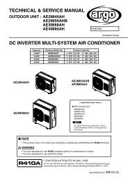
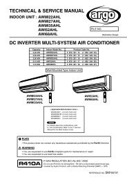
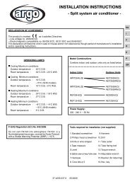
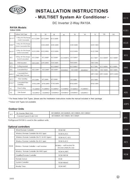
INSTALLATION INSTRUCTIONS- MULTISET System Air Conditioner -A S 1SDC <strong>Inverter</strong> 2-Way R410AR410A ModelsIndoor UnitsA S B SAS 1S **AS B S **Indoor Unit TTypeype 22 28 36 45 56 64 73106 1 401-Way Air DischargeAS 1S 22MH AS 1S 28MH AS 1S 36MHS emi-CS emi-Concealedoncealed1-Way Air DischargeAS B S 28MH AS B S 36MH AS B S 56MH AS B S 73MHS emi-C oncealed Slimemi-C oncealed S limA S 2SAS 2S **AS S2-Way Air DischargeS Semi-C oncealed oncealed4-Way Air DischargeS emi-C S emi-C oncealed* oncealedAS 2S 22MH AS 2S 28MH AS 2S 36MH AS 2S 56MH AS 2S 73MHAS S 22MH* AS S 28MH* AS S 36MH* AS S 45MH*G AS S 56MH* AS S 73MH* AS S 106MH* AS S 140MH*A S SAW S W Wall-mounteda ll-MountedAWS 22MH A WS 28MH A WS 36MH AWS 56MH AWS 73MHAC S C eiling-Mounted C eiling-mountedAC S 36MH** AC S 56MH** AC S 73MH AC S 106MH AC S 140MHADS C C oncealed-Duct ADS 22MH* ADS 28MH* ADS 36MH* AD45MHG * ADS 56MH* AD64MHG * ADS 73MH ADS 106MH ADS 140MHADP S **C C oncealed-DuctHigh-S tatic P ressureHigh S tatic ressure*ADP S 73MH ADP S 106MH ADP S 140MHAF S ** F loor-standingF loor-S tandingAF S 22MH AF S 28MH AF S 36MH AF S 56MH AF S 73MHAF NS ** C oncealed-F C oncealed-F loor- loorS tandingAF NS 22MH AF NS 28MH A F NS 36MH AF NS 56MH AF NS 73MHAW SA C SF CF loor-C eilingF C 22MHG * F C 28MHG * F C 36MHG * F C 45MHG * F C 56MHG * F C 64MHG *S DS lim DuctedS D22MHG * S D28MHG * S D36MHG * S D45MHG * S D56MHG * S D64MHG *A DS* For these Indoor Unit Types, please see the installation instructions inside the manual included in their package**Indoor Unit Types not availableOutdoor UnitsDc <strong>Inverter</strong> Main UnitAE SC onstant S peed (S ub) UnitR efrigerant R 410A is used in the outdoor unitsAE S 06MI2H, AE S 0 8MI2H, AE S 10MI2H, AE S 12MI2HAE S 08M2H, AE S 10M2H, AE S 12M2HADP SA F SOptional controllersWired R emote R emote C ontroller C ontrollerWireless R emote C ontroller (for (F or AS AS S S type) type)Wireless R emote C ontroller (for (F or F C AS& 2S AS, AS S types) B S type)R E M HWR E M HLAS SR E M HLF C AS SA F NSR E MWireless R emote C ontroller (for (F or AC AC S S type) type)Wireless R emote C ontrollerWireless R emote Controller + wal l receiverR E M HLAC SR E MHL + wall receiver forAS S /AC S /ADS /F C /S DA E SWireless R emote C ontroller (for (F or AWS A type)S implified R emote C ontrollerR E M HLAWSR E M HWS MR E MR emote S ensorR S MS ystem C ontrollerR E M HW64SWeekly S chedule Timer TimerR E M HWT2005W
<strong>04</strong>-<strong>396</strong> <strong>Inverter</strong>-W_a-<strong>p50</strong> <strong>ARGO</strong> 12/21/<strong>04</strong> 9:38 AM Page 3Check of Density LimitThe room in which the air conditioner is to beinstalled requires a design that in the event ofrefrigerant gas leaking out, its density will notexceed a set limit.The refrigerant (R410A), which is used in the air conditioner,is safe, without the toxicity or combustibility ofammonia, and is not restricted by laws imposed to protectthe ozone layer. However, since it contains morethan air, it poses the risk of suffocation if its densityshould rise excessively. Suffocation from leakage ofrefrigerant is almost non-existent. With the recentincrease in the number of high density buildings, however,the installation of multi air conditioner systems ison the increase because of the need for effective useof floor space, individual control, energy conservationby curtailing heat and carrying power, etc.Most importantly, the multi air conditioner system isable to replenish a large amount of refrigerant comparedto conventional individual air conditioners. If asingle unit of the multi air conditioner system is to beinstalled in a small room, select a suitable model andinstallation procedure so that if the refrigerant accidentallyleaks out, its density does not reach the limit(and in the event of an emergency, measures can bemade before injury can occur).In a room where the density may exceed the limit,create an opening with adjacent rooms, or installmechanical ventilation combined with a gas leakdetection device. The density is as given below.Total amount of refrigerant (kg)Min. volume of the indoor unit installed room (m 3 )≤ Density limit (kg/m 3 )The density limit of refrigerant which is used in multi air conditionersis 0.3 kg/m 3 (ISO 5149).NOTE1. If there are 2 or more refrigerating systems in a singlerefrigerating device, the amount of refrigerantshould be as charged in each independent device.For the amount of charge in this example:2. The standards for minimum room volume are asfollows.(1) No partition (shaded portion)(2) When there is an effective opening with the adjacentroom for ventilation of leaking refrigerant gas(opening without a door, or an opening 0.15% orlarger than the respective floor spaces at the topor bottom of the door).Outdoor unitRefrigerant tubingIndoor unit(3) If an indoor unit is installed in each partitionedroom and the refrigerant tubing is interconnected,the smallest room of course becomes the object.But when mechanical ventilation is installed interlockedwith a gas leakage detector in the smallestroom where the density limit is exceeded, the volumeof the next smallest room becomes the object.VerysmallroomSmallroomMediumroomRefrigerant tubingLarge roomOutdoor unitIndoor unitMechanical ventilation device – Gas leak detector3. The minimum indoor floor space compared with theamount of refrigerant is roughly as follows: (Whenthe ceiling is 2.7 m high)e.g., chargedamount (10 kg)Indoor unitOutdoor unite.g., chargedamount (15 kg)Room A Room B Room C Room D Room E Room FThe possible amount of leaked refrigerant gas in roomsA, B and C is 10 kg.The possible amount of leaked refrigerant gas in roomsD, E and F is 15 kg.m 2Min. indoor floor space4035302520151050Range below thedensity limitof 0.3 kg/m 3(countermeasuresnot needed)Range abovethe density limitof 0.3 kg/m 3(countermeasuresneeded)10 20 30Total amount of refrigerantkg3
<strong>04</strong>-<strong>396</strong> <strong>Inverter</strong>-W_a-<strong>p50</strong> <strong>ARGO</strong> 12/21/<strong>04</strong> 9:38 AM Page 4Precautions for Installation Using New Refrigerant1. Care regarding tubing1-1. Process tubing● Material: Use C1220 phosphorous deoxidized copper specified in JIS H3300 “Copper and Copper Alloy SeamlessPipes and Tubes.”For tubes of φ19.05 or larger, use C1220 T-1/2H material or H material, and do not bend the tubes.● Tubing size: Be sure to use the sizes indicated in the table below.● Use a tube cutter when cutting the tubing, and be sure to remove any flash. This also applies to distributionjoints (optional).● When bending tubing φ15.88 or smaller, use a bending radius that is 4 times the outer diameter of the tubing or larger.CAUTIONUse sufficient care in handling the tubing. Seal the tubing ends withcaps or tape to prevent dirt, moisture, or other foreign substancesfrom entering. These substances can result in system malfunction.Copper tubeCopper tubeUnit: mmMaterial 0Outer diameter 6.35 9.52 12.7 15.88Wall thickness 0.8 0.8 0.8 1.0Material1/ 2 H, HOuter diameter 19.05 22.22 25.4 28.58 31.75 38.1Wall thickness 1.0 1.0 1.0 1.0 1.1 1.351-2. Prevent impurities including water, dust and oxide from entering the tubing. Impurities can cause R410Arefrigerant deterioration and compressor defects. Due to the features of the refrigerant and refrigeratingmachine oil, the prevention of water and other impurities becomes more important than ever.2. Be sure to recharge the refrigerant only in liquid form.2-1. Since R410A is a non-azeotrope, recharging the refrigerant in gas form can lower performance and causedefects of the unit.2-2. Since refrigerant composition changes and performance decreases when gas leaks, collect the remainingrefrigerant and recharge the required total amount of new refrigerant after fixing the leak.3. Different tools required3-1. Tool specifications have been changed due to the characteristics of R410A.Some tools for R22- and R407C-type refrigerant systems cannot be used.Item New R407C tools Remarkstool compatiblewith R410AManifold gaugeManifold gauge Yes No Types of refrigerant, refrigerating machineoil, and pressure gauge are different.Charge hose Yes No To resist higher pressure, material must be changed.Vacuum pump Yes Yes Use a conventional vacuum pump if it is equippedwith a check valve. If it has no check valve,purchase and attach a vacuum pump adapter.Leak detector Yes No Leak detectors for CFC and HCFC thatreact to chlorine do not function becauseR410A contains no chlorine. Leak detectorfor HFC134a can be used for R410A.Vacuum pumpOutletInletFlaring oil Yes No For systems that use R22, apply mineral oil (Suniso oil)to the flare nuts on the tubing to prevent refrigerantleakage. For machines that use R407C or R410A, applysynthetic oil (ether oil) to the flare nuts.* Using tools for R22 and R407C and new tools for R410A together can cause defects.4
IntroductionxiiiIntroduction: “To the greatVariety of Readers”Reade him, therefore; and againe, and againe: And if then you doe not like him,surely you are in some manifest danger, not to understand him.John Heminge, Henry Condell, 1623 FolioWhy should we read Shakespeare, again and again, with youngadults in classrooms across the country? And if we can agreeupon some answers to that question, the corollary ensues—How?This book began years before I wrote it with a series of questionsI couldn’t answer on my own. But at the core of all my interrogativesthere stood a stubborn, imperative spine: Speaking Shakespeare, writingabout Shakespeare, performing Shakespeare, listening to and viewingShakespeare, all proceed from reading Shakespeare, and the act of readingShakespeare is something we need to understand.Reading Shakespeare with Young Adults celebrates the collaborativereading of Shakespeare’s plays. Collaborative as in what we can learnfrom classroom teachers, adolescents, literacy researchers, Shakespeareanscholars, performers, and media specialists; reading as in what wecan do with increasing independence to construct meaning from thetransaction with challenging content written in early modern English;plays as in what we can apply to thirty-seven of them because the readingskills and strategies outlined in this book are transferable across thecollection of Shakespeare’s plays.This book is written by an English teacher who knows firsthandthe complexity, the challenge, and the reward of working with apprenticereaders in the secondary classroom. The students at my school bearevery label the educational system can muster—advanced, at-risk, mainstream,minority, English language learner, limited English proficient,straight, gay, special needs. In the crucible that is the twenty-first-centuryAmerican classroom, reading Shakespeare with all of these studentshas become the most rewarding transaction we share. I use the wordtransaction as Louise Rosenblatt defines it in her preface to Literature asExploration to suggest the infinite ways in which meaning “‘happens’during the transaction between the reader” and a word, a line, a speech,or a scene in a Shakespearean play (xvi).
<strong>04</strong>-<strong>396</strong> <strong>Inverter</strong>-W_a-<strong>p50</strong> <strong>ARGO</strong> 12/21/<strong>04</strong> 9:38 AM Page 74. HOW TO INSTALL THE OUTDOOR UNIT . . .794-1. Transporting4-2. Installing the Outdoor Unit5. ELECTRICAL WIRING . . . . . . . . . . . . . . . . . . .815-1. General Precautions on Wiring5-2. Recommended Wire Length and Wire Diameterfor Power Supply System5-3. Wiring System Diagrams6. HOW TO INSTALL THE REMOTE CONTROLLER(OPTIONAL PART) . . . . . . . . . . . . . . . . . . . . . .856-1. When Using a Wall Box for Flush Mounting6-2. Basic Wiring Diagram6-3. Wiring System Diagram for Group Control6-4. Switching the Room Temperature Sensors6-5. Connecting to a Ventilation Fan6-6. Wiring the Remote Controller6-7. Meanings of Alarm Messages7. HOW TO PROCESS TUBING . . . . . . . . . . . . .937-1. Connecting the Refrigerant Tubing7-2. Connecting Tubing Between Indoor andOutdoor Units7-3. Insulating the Refrigerant Tubing7-4. Taping the Tubes7-5. Finishing the Installation8. AIR PURGING . . . . . . . . . . . . . . . . . . . . . . . . .97■ Air Purging with a Vacuum Pump (for Test Run)PreparationPage9. HOW TO INSTALL THE CEILING PANEL . . .100■ 1-Way Air Discharge Semi-Concealed Type(AS1S Type) . . . . . . . . . . . . . . . . . . . . . . . . . .1009-1. Installing the Ceiling Panel9-2. How to Use the Stoppers■ 1-Way Air Discharge Semi-Concealed Slim Type(ASBS Type) . . . . . . . . . . . . . . . . . . . . . . . . . .1019-3. Installing the Ceiling Panel■ 2-Way Air Discharge Semi-Concealed Type(AS2S Type) . . . . . . . . . . . . . . . . . . . . . . . . . .1039-4. Before Installing the Ceiling Panel9-5. Installing the Ceiling Panel9-6. When Removing the Ceiling Panel for Servicing■ 4-Way Air Discharge Semi-Concealed Type(ASS Type) . . . . . . . . . . . . . . . . . . . . . . . . . . .1059-7. Before Installing the Ceiling Panel9-8. Installing the Ceiling Panel9-9. Wiring the Ceiling Panel9-10. How to Attach the Corner & Air Intake Grille9-11. Checking After Installation9-12. When Removing the Ceiling Panel for Servicing9-13. Adjusting the Auto Flap10. TEST RUN . . . . . . . . . . . . . . . . . . . . . . . . . . .10910-1. Preparing for Test Run10-2. Test Run Procedure10-3. Main Outdoor Unit PCB Setting10-4. Sub Outdoor Unit PCB Setting10-5. Auto Address Setting10-6. Caution for Pump Down11. HOW TO INSTALL THE WIRELESS REMOTECONTROLLER RECEIVER . . . . . . . . . . . . . .122■ REM HLASS for 4-Way Cassette (ASS Type) . .12211-1. Installing the Receiver Unit11-2. Accessories11-3. Wiring the Receiver Unit11-4. Precautions on Simultaneous Installation ofWired Remote Controller and WirelessRemote Controller11-5. How to use the Test Run Setting■ REM HLACS for Ceiling Mounted (ACS Type) .12511-6. Installing the Receiver Unit11-7. Accessories Supplied with Unit11-8. Wiring the Receiver Unit11-9. Precautions on Simultaneous Installation ofWired Remote Controller and WirelessRemote Controller11-10. How to Use the Test Run Setting■ REM HLAS2BS for 2-Way and High Ceiling1-Way Type (AS2S, ASBS Type) . . . . . . . . . .12811-11. Installing the Display11-12. Installing the Control Unit11-13. Installing the Display11-14. Installing the Control Unit11-15. Accessories11-16. Wiring the Receiver Unit11-17. Precautions on Simultaneous Installation ofWired Remote Controller and WirelessRemote Controller11-18. How to Use the Test Run Setting■ REM HL for AS1S, ADS, ADPS, AFS, AFNS Type. . . . . . . . . . . . . . . . . . . . . . . . . . . . . . . .13311-19. Accessories Supplied with SeparateReceiver Unit11-20. Important Information for Installation of1 Separate Receiver Unit11-21. How to Install the Separate Receiver Unit11-22. Wiring the Separate Receiver Unit11-23. Important Information for Installation of2 Separate Receiver Units11-24. Test Run Setting12. SPECIAL REMARKS . . . . . . . . . . . . . . . . . . .139■ DC Fan Tap Change Procedure for 4-WayCassete (ASS Type)Page7
<strong>04</strong>-<strong>396</strong> <strong>Inverter</strong>-W_a-<strong>p50</strong> <strong>ARGO</strong> 12/21/<strong>04</strong> 9:38 AM Page 9Table 1-1 (1-Way Air Discharge Semi-Concealed)Part Name Figure Q’ty RemarksFlare insulator 2For wide and narrow tubesInsulating tape(Black)(White)32For wide and narrow tubesFor wide and narrow tube flare nutsVinyl clamp 8Hose band 1Packing 1For flare insulatorFor securing drain hoseFor drain jointDrain insulator 1 For drain jointDrain hose1 For securing drain hoseInstallation gauge1For measuring clearance between the unit and ceilingSpecial washer8For suspension boltsTable 1-2 (1-Way Air Discharge Semi-Concealed Slim)Part Name Figure Q’ty RemarksFull-scale installation diagram 1Special washer 8Flare insulator 2(Black) 2Insulating tape(White) 2Vinyl clamp 8Hose band 1Packing 1Drain insulator 1Sealing putty 1Cable 1Drain hose 1For determining suspension bolt pitchFor temporarily suspending indoor unit from ceilingFor wide and narrow tubesFor wide and narrow tubesFor wide and narrow tube flare nutsFor flare insulatorFor securing drain hoseFor drain jointFor drain jointFor sealing recessed portion of power supplyConnection cable for fan motorFor securing drain hose9
<strong>04</strong>-<strong>396</strong> <strong>Inverter</strong>-W_a-<strong>p50</strong> <strong>ARGO</strong> 12/21/<strong>04</strong> 9:38 AM Page 15Table 1-17 Refrigerant Charge Amount at Shipment (for outdoor unit)DC AES06MI2H AES08MI2H AES10MI2H AES12MI2H(kg) 7.5 10.0 10.0 10.0AD – AES08M2H AES10M2H AES12M2H(kg) – 10.0 10.0 10.01-8. Combination of Outdoor UnitsAs shown in Table 1-18, a DC unit can be used independently or in combination with an AD unit.CAUTION● Sub units cannot be used independently.Table 1-18 Combination of Outdoor UnitsTotal cooling capacity 16.0 22.4 28.0 33.5 40.0 45.0 50.4 56.0 61.5 68.0 73.0 78.5 85.0 90.0(kW)DC INV. unit (main) 06 08 10 12 06 08 10 10 12 12 10 10 10 12AD unit (sub)08 08 08 10 10 12 08 10 10 1008 08 10 10Total cooling capacity 96.0 101.0 106.5 113.0 118.0 123.5 130.0 135.0(kW)DC INV. unit (main) 12 12 10 10 12 12 12 1212 12 10 10 10 12 12 12AD unit (sub) 10 12 10 10 10 10 12 1208 10 10 10 10 121-9. System LimitationsTable 1-19 System LimitationsMax. No. allowable connected outdoor units 4Max. capacity allowable connected outdoor units135 kW (48 hp)Max. connectable indoor units 40Max. allowable indoor/outdoor capacity ratio 50 – 130 %15
<strong>04</strong>-<strong>396</strong> <strong>Inverter</strong>-W_a-<strong>p50</strong> <strong>ARGO</strong> 12/21/<strong>04</strong> 9:38 AM Page 161-10. Tubing LengthSelect the installation location so that the length and size of refrigerant tubing are within the allowable range shownin the figure below.DSubunitCSubunitL51.2.3.Main tubing length LM = LA + LB … ≤ 80 mMain distribution tubes LC – LH are selected according to the capacity after thedistribution joint.Sizes of indoor unit connection tubing 1 – 40 are determined by the connectiontubing sizes on the indoor units.H3DCSubunitBMainunitAL2BLMAL1Balance tubing(ø9.52)Explanation of symbolsLO2LO1Distribution joint(DDVE & DDVI: purchased separately)special tubing for R410ALALFLBMax. 40cmMax. 40cmLCForextensionLD4ForextensionLHLE5640H2H1Ball valve (BV: purchasedseparately)special valve for R410ALG123Note: Do not use commercially available T-joints for the liquid tubing and parts.* Be sure to use special R410A distribution joints (DDV: purchased separately) for outdoorunit connections and tubing branches.L4R410A distribution jointDDVE135 (for outdoor unit)DDVE68 (for outdoor unit)DDVI135 (for indoor unit)DDVI68 (for indoor unit)DDVI16 (for indoor unit)Table 1-20 Ranges that Apply to Refrigerant Tubing Lengths and to Differences in Installation HeightsNOTEItems Marks Contents Length (m)Allowable tubinglengthAllowable elevationdifferenceL = Length, H = HeightL1Max. tubing length1: The tubing size (LO1, LO2) connecting the outdoor units to one another is decided by the total capacity of theoutdoor units connected at tubing ends. The LO1 tubing size is determined by the total capacity of the 3 subunits B, C, and D, which are connected after main unit A. The LO2 tubing size is determined by the total capacityof sub units C and D, which are connected after sub unit B. Refer to Table 1-11a.2: If the maximum tubing length (L1) exceeds 90 m (or equivalent length), increase the size of both the narrowand wide main tubing (LM) by 1 step. However, the maximum wide tubing size is φ38.1. In addition, it is notnecessary to increase the tubing sizes in the case of a 6-horsepower system. (Tubing reducers must beobtained in the field.)16Actual length 150Equivalent length 175∆L (L2 – L4)Difference between max. length and min.length from the No.1 distribution joint40LM Max. length of main tubing (at max. diameter) 801, 2 ~ 40 Max. length of each distribution tube 30L1+ 1 + 2 +~ 40 Total max. tubing length including length of+ A+ B +LF+LG+LH each distribution tube (only narrow tubing)300L5 Distance between PC and AD unit 10H1When outdoor unit is installed higher than indoor unit 50When outdoor unit is installed lower than indoor unit 40H2 Max. difference between indoor units 15H3 Max. difference between outdoor units 4>>>>>>>>>>>
<strong>04</strong>-<strong>396</strong> <strong>Inverter</strong>-W_a-<strong>p50</strong> <strong>ARGO</strong> 12/21/<strong>04</strong> 9:38 AM Page 17WARNINGAlways check the gas densitylimit for the room inwhich the unit is installed.1-11. Check of Limit DensityWhen installing an air conditioner in a room, it is necessaryto ensure that even if the refrigerant gas accidentallyleaks out, its density does not exceed the limitlevel for that room.If the density could exceed the limit level, it is necessaryto provide an opening between the unit and theadjacent room, or to install mechanical ventilationwhich is interlocked with the leak detector.(Total refrigerant charged amount: kg)(Min. indoor volume where the indoor unit is installed: m 3 )≤ Limit density 0.3 (kg/m 3 )The limit density of refrigerant which is used in this unitis 0.3 kg/m 3 (ISO 5149).The shipped outdoor unit comes charged with theamount of refrigerant fixed for each type, so add it tothe amount that is charged in the field. (For the refrigerantcharge amount at shipment, refer to the unit’snameplate.)CAUTION1-12. Installing Distribution JointPay special attention to anylocation, such as a basement,etc., where leaking refrigerantcan accumulate, since refrigerantgas is heavier than air.(1) Refer to “HOW TO ATTACH DISTRIBUTIONJOINT” enclosed with the optional distribution jointkit (DDVE135, DDVE68, DDVI135, DDVI68,DDVI16).(2) In order to prevent accumulation of refrigerant oil instopped units, if the main tubing is horizontal theneach branch tubing length should be at an angle thatis greater than horizontal. If the main tubing is vertical,provide a raised starting portion for each branch.(3) If there are height differences between indoor unitsor if branch tubing that follows a distribution joint isconnected to only 1 unit, a trap or ball valve must beadded to that distribution joint. (When adding the ballvalve, locate it within 40 cm of the distribution joint.)(Consult with <strong>ARGO</strong> separately concerning the ballvalve.)If a trap or ball valve is not added, do not operatethe system before repairs to a malfunctioningunit are completed. (The refrigerant oil sentthrough the tubing to the malfunctioning unit willaccumulate and may damage the compressor.)Minimum indoor volume & floor area as against theamount of refrigerant is roughly as given in the followingtable.Min. indoor floor area(when the ceiling is 2.7 m high)m 2100m 3270.095 256.590 243.085 229.5 Range below the80 216.0density limit of0.3 kg/m75 202.5(Countermeasures70 189.0 not needed)65 175.560 162.055 148.550 135.0Range above the45 121.5density limit of0.3 kg/m40 108.0(Countermeasures35 94.5needed)30 81.025 67.5201554.<strong>04</strong>0.520 30 40 50 60 70 80 kgTotal amount of refrigerantMin. indoor volumeTube branching methods (horizontal use)Ball valve(BV: purchasedseparately)Main tubingBMain tubingAArrow view15 to 30°BHorizontal Aline View as seenfrom arrowTypes of vertical trap specifications(When using ball valve)Indoor unit (1)Indoor unit (more than 2 units)(If only 1 unit is connected, a ballvalve is also needed on this side.)(When not using ball valve)HorizontalIndoor unitBranch tubing isdirected upward.More than20 cmIndoor unit is directed downward(Each unit isconnected to tubingthat is either level oris directeddownward.)17
<strong>04</strong>-<strong>396</strong> <strong>Inverter</strong>-W_a-<strong>p50</strong> <strong>ARGO</strong> 12/21/<strong>04</strong> 9:38 AM Page 181-13. Optional Distribution Joint KitsSee the installation instructions packaged with the distribution joint kit for the installation procedure.Table 1-21Model name Cooling capacity after distribution Remarks1. DDVE68 68.0 kW or less For outdoor unit2. DDVE135 135.0 kW or less For outdoor unit3. DDVI16 22.4 kW or less For indoor unit4. DDVI68 68.0 kW or less For indoor unit5. DDVI135 135.0 kW or less For indoor unit1. DDVE68Use: For outdoor unit (Capacity after distribution joint is 68.0 kW or less.)Example: (G below indicates inner diameter.G below indicates outer diameter.)Wide tubeNarrow tubeI53 395 74HGGCD EE FF G GFE EFG GD C D IH HI340 50DDE230 F126130Thermal insulationThermal insulationTable 1-22 Dimensions for connections of each partUnit: mmPosition A B C D E F G H I JDimension – – φ28.58 φ25.4 φ22.22 φ19.05 φ15.88 φ12.7 φ9.52 –2. DDVE135Use: For outdoor unit (Capacity after distribution joint is greater than 68.0 kW and no more than 135.0 kW.)Example: (G below indicates inner diameter.G below indicates outer diameter.)Wide tube622Narrow tubeIHB ABCDG GFEG G FEEFG G130DEF195IHHI340 50315B AInsulatorInsulatorTable 1-23 Dimensions for connections of each partUnit: mmPosition A B C D E F G H I JDimension φ38.1 φ31.75 φ28.58 φ25.4 φ22.22 φ19.05 φ15.88 φ12.7 φ9.52 –18
<strong>04</strong>-<strong>396</strong> <strong>Inverter</strong>-W_a-<strong>p50</strong> <strong>ARGO</strong> 12/21/<strong>04</strong> 9:38 AM Page 193. DDVI16Use: For indoor unit (Capacity after distribution joint is 22.4 kW or less.)Example: (F below indicates inner diameter.Fbelow indicates outer diameter.)Wide tube210 55Narrow tube185 50HGF F FHF GH JFF HGH145 135103HJHHJ83InsulatorInsulator4. DDVI68Use: For indoor unit (Capacity after distribution joint is greater than 22.4 kW and no more than 68.0 kW.)Example: (F below indicates inner diameter.Fbelow indicates outer diameter.)Wide tubeNarrow tube300 112 55 210 72C C C DEF GHFEDC FC230CD141GG G HI JJIHG145 GG HIJ103InsulatorFEFGHInsulatorTable 1-24 Dimensions for connections of each partUnit: mmPosition A B C D E F G H I JDimension – – φ28.58 φ25.4 φ22.22 φ19.05 φ15.88 φ12.7 φ9.52 φ6.355. DDVI135Use: For indoor unit (Capacity after distribution joint is greater than 68.0 kW and no more than 135.0 kW.)Example: (F below indicates inner diameter.Fbelow indicates outer diameter.)HFIJGF ENarrow tube H GDGWide tube CFECAB G GFEEFG GJIHHIJFEDC CAB B BAC CDEF340 72B B90 105 11245130InsulatorInsulatorTable 1-25 Dimensions for connections of each partUnit: mmPosition A B C D E F G H I JDimension φ38.1 φ31.75 φ28.58 φ25.4 φ22.22 φ19.05 φ15.88 φ12.7 φ9.52 φ6.3519
<strong>04</strong>-<strong>396</strong> <strong>Inverter</strong>-W_a-<strong>p50</strong> <strong>ARGO</strong> 12/21/<strong>04</strong> 9:38 AM Page 201-14. Optional Ball Valve KitsTable 1-26Model No.NOTEValve connecting tube size (mm)Wide tube Narrow tube Balance valveIndoor unit where usedOutdoor unit where used Total capacity of indoor unitsafter the valveBV-RXP335AG 25.4 12.7 – 12 hp More than 30.0 kW and less than 42.0 kWBV-RXP280AG 22.22 9.52 – 10 hp Less than 30.0 kWBV-RXP224AG 19.05 9.52 – 6, 8 hp 22.4 kW or lessBV-RXP160AG 15.88 9.52 – – 16.0 kW or lessBV-RXP56AG 12.7 6.35 – – 5.6 kW or lessBV-RP3G – – 9.52 For balance tube –hp: horse power1. Because the diameter of this ball valve is approximately the same as the inner diameter of the connecting coppertube, correction for pressure loss is not necessary.2. Airtightness must be 3.8 MPa or more.* It is recommended that this part be installed at each outdoor unit (wide tube and narrow tube), in order to preventrefrigerant from being released into the atmosphere if the outdoor unit is eventually replaced.DimensionsType with flare nut at each endAFigureEDDimensionsSizeø6.35 (1/4")ø9.52 (3/8")ø12.7 (1/2")ø15.88 (5/8")Unit: mmA B C D E72768910842424251545458681616202244445156BCInsulator(divided in 2)2 - ø 7Service port30˚Type that is welded at each endAEDø19.05 (3/4")ø22.22 (7/8")2502505151686822225656BCInsulator(divided in 2)2 - ø 7Service port30˚Type that is welded at each endø25.4 (1") 250 55 69 36 84.5AEDBCInsulator(divided in 2)2 - ø 7Service port30˚Note: Install the service port so that it faces the extension side.20
<strong>04</strong>-<strong>396</strong> <strong>Inverter</strong>-W_a-<strong>p50</strong> <strong>ARGO</strong> 12/21/<strong>04</strong> 9:38 AM Page 21Ball Valve Installation (for refrigerant R410A only)Check the size of the ball valve set you separately purchased.Model nameSizeValves with φ19.05, φ22.22, or φ25.4 connections are brazing type.BV-RXP56AG φ6.35 • φ12.7 All others are flare-nut type.BV-RXP160AG φ9.52 • φ15.88BV-RXP224AG φ9.52 • φ19.05BV-RXP280AG φ9.52 • φ22.22BV-RXP335AG φ12.7 • φ25.41. Installing the ball valve(1) If the ball valve is to be installed on the outdoorunit side, or for outdoor unit extension, install it sothat the service port faces the outdoor unit side.Outdoor unitextensionOutdoor unitService port(2) If the ball valve is to be installed for indoor unitextension, or near an indoor unit, install it so thatthe service port faces the indoor unit side.(This facilitates indoor unit leak testing and vacuumprocedures.)Install the ball valve as close as possible to thedistribution joint.Ball valveIndoorBall valveOutdoorCAUTIONThis ball valve is for useonly in systems that utilizerefrigerant R410A. The serviceport connection size isφ7.94. The face-to-face distancebetween the φ12.7 orφ15.88 flare nuts is 26 mmor 29 mm, respectively.Be sure to use only thesupplied flare nuts. Becareful to use the correcttools and materials.ServiceportIndoor unitIndoor unit extension2. Flare nut tightening, welding plugThe flare nut on the service port side is fully tightened.In the case of the welded type, a plug iswelded in place.If the valve is used for extension, it can be usedas-is. In all other cases, use 2 monkey wrenchesin combination to loosen the flare nut. In the caseof the brazed type, heat with a brazing torch andremove the plug. At this time, use a damp shopclothor other means to cool the brazed-type ballvalve unit while using the torch.When performing brazing, be sure to replace theair in the tubing with nitrogen in order to preventthe formation of oxide film.Fully tightened (this side only)Service portPlug(this side only)Service portCool with damp shopcloth or othermeans when heating brazed plugwith torch.21
<strong>04</strong>-<strong>396</strong> <strong>Inverter</strong>-W_a-<strong>p50</strong> <strong>ARGO</strong> 12/21/<strong>04</strong> 9:38 AM Page 223. Opening and closing the valveThis valve is open at the time of shipment from thefactory. If the valve is used for extension, be sureto close it.Valve openedSpindleValve closedSpindle4. Installing thermal insulationThe thermal insulation used for a flare-nut typevalve is in the form of a bag. When the valve isused for extension, it can be used as-is. If thevalve is used for any other purpose, use a boxcutter or similar tool to cut away the part shown inthe figure at right.The insulation is divided into 2 parts. After performingthe leak test, use vinyl tape or othermeans to temporarily fasten the 2 parts together.Then carry out final finishing.InsulatorNotch22
<strong>04</strong>-<strong>396</strong> <strong>Inverter</strong>-W_a-<strong>p50</strong> <strong>ARGO</strong> 12/21/<strong>04</strong> 9:38 AM Page 231-15. Recommended Location of Ball Valves● It is recommended that a ball valve kit be installed for each outdoor unit.● Select a valve location that allows service to be easily provided for each unit or each refrigerant system.(1) When adding ball valve for indoor unit1. Location: Install the ball valve at the distribution tube (not main tube).Outdoor unitDistribution jointMain tubeDistribution tubeMain tubeBall valve (for extension)Required additionalrefrigerant charge (kg)Distribution tubeBall valve (for extension)Less than 40 cmIndoor unit for extensionIndoor unit for extension2. Installation requirements• Be sure to install the ball valve up-grade to prevent the inadvertent flow of oil.• Install the ball valve at the shortest distance (within 40 cm) from the main tube. If the diameter of the ball valveis smaller than that of the main tube, use a reducer or the like to reduce the size of the tubing at that location.• Select a place where it is easy to operate, using careful consideration of the location in advance.(2) When adding ball valve for outdoor unit1. Location: Install the ball valve at the main tube of the distribution joint.Outdoor unitfor extensionBall valve (for service)Ball valve (for extension)Balance tubeWide tubeNarrow tubeMain tube of distribution jointMain tubeTo indoor unit2. Installation requirements• Be sure to install the ball valve up-grade to prevent the inadvertent flow of oil.• Install the ball valve at the shortest distance (within 40 cm) from the main tube. If the diameter of the ball valveis smaller than that of the main tube, use a reducer or the like to reduce the size of the tubing at that location.NOTE• If the ball valve is installed at the outdoor unit (including extension for outdoor unit), face the service port ofthe valve toward the outdoor unit side (see above illustration; dotted line) and allow a distance of over 50 cmfrom the outdoor unit. If the ball valve is installed between the indoor unit (including extension for indoor unit)and the main tube, face the ball valve toward the indoor unit side (see above illustration; dotted line).23
<strong>04</strong>-<strong>396</strong> <strong>Inverter</strong>-W_a-<strong>p50</strong> <strong>ARGO</strong> 12/21/<strong>04</strong> 9:38 AM Page 241-16. Example of Tubing Size Selection and Refrigerant Charge AmountAdditional refrigerant chargingBased on the values in Tables 1-11a, 11b, 12, 13 and 16, use the narrow tubing size and length, and calculate theamount of additional refrigerant charge using the formula below.Required additionalrefrigerant charge (kg)= [366 × (a) + 259 × (b) + 185 × (c) + 128 × (d) + 56 × (e) + 26 × (f)] × 10 –3(a) : Narrow tubing Total length of φ22.22 (m) (d) : Narrow tubing Total length of φ12.7 (m)(b) : Narrow tubing Total length of φ19.05 (m) (e) : Narrow tubing Total length of φ9.52 (m)(c) : Narrow tubing Total length of φ15.88 (m) (f) : Narrow tubing Total length of φ6.35 (m)● Charging procedureBe sure to charge with R410A refrigerant in liquid form.1. After performing a vacuum, charge with refrigerant from the narrow tubing side. At this time, all valves mustbe in the “fully closed” position.2. If it was not possible to charge the designated amount, operate the system in Cooling mode while chargingwith refrigerant from the wide tubing side. (This is performed at the time of the test run. For this, all valvesmust be in the “fully open” position.)Charge with R410A refrigerant in liquid form.With R410A refrigerant, charge while adjusting the amount being fed a little at a time in order to preventliquid refrigerant from backing up.● After charging is completed, turn all valves to the “fully open” position.● Replace the tubing covers as they were before.Example:CAUTIONOutdoor unit1. R410A additional charging absolutely must be donethrough liquid charging.2. The R410A refrigerant cylinder has a gray basecolor, and the top part is pink.3. The R410A refrigerant cylinder includes a siphontube. Check that the siphon tube is present. (This isindicated on the label at the top of the cylinder.)4. Due to differences in the refrigerant, pressure, andrefrigerant oil involved in installation, it is not possiblein some cases to use the same tools for R22 andfor R410A.08model10 Main unitmodel 10modelCBALB LC LD LE LFLOLA1 2 3 4 5 6 7106 model 106 model 140 model 140 model 140 model 73 model 140 model● Example of each tubing lengthMain tubingDistribution joint tubingLO = 2 m LD = 15 m Outdoor side Indoor sideLA = 40 m LE = 10 m A = 1.5 m 1 = 30 m 5 = 2 mLB = 5 m LF = 10 m B = 1.5 m 2 = 5 m 6 = 6 mLC = 5 m C = 2 m 3 = 5 m 7 = 5 m4 = 5 m24
<strong>04</strong>-<strong>396</strong> <strong>Inverter</strong>-W_a-<strong>p50</strong> <strong>ARGO</strong> 12/21/<strong>04</strong> 9:38 AM Page 25● Obtain narrow tubing size from Tables 1-11a, 11b, 12, 13 and 16.Main tubingLO = φ15.88 m (Total capacity of outdoor unit is 50.4 kW)LA = φ19.05 m (Total capacity of indoor unit is 88.4 kW) The longest tubing length in this exampleLB = φ19.05 m (Total capacity of indoor unit is 77.2 kW) (LM = 40 + 5 = 45 m)LC = φ15.88 m (Total capacity of indoor unit is 66.0 kW)LD = φ15.88 m (Total capacity of indoor unit is 52.0 kW)LE = φ12.7 m (Total capacity of indoor unit is 38.0 kW)LF = φ9.52 m (Total capacity of indoor unit is 22.0 kW)Distribution joint tubingOutdoor side A: φ9.52 B: φ9.52 C: φ9.52 (from outdoor unit connection tubing)Indoor side 1: φ9.52 2: φ9.52 3: φ9.52 4: φ9.525: φ9.52 6: φ9.52 7: φ9.52 (from indoor unit connection tubing)● Obtain charge amount for each tubing sizeNote that the charge amounts per 1 meter are different for each narrow tubing size.φ19.05 → LA + LB : 45m × 0.259 kg/m = 11.655φ15.88 → LO + LC + LD : 22 m × 0.185 kg/m = 4.07φ12.7 → LE : 10 m × 0.128 kg/m = 1.28φ9.52 → LF + A – C + 1 – 7 : 73 m × 0.056 kg/m = 4.088Total 21.093 kgAdditional refrigerant charge amount is 21.093 kg.CAUTIONBe sure to check the limit densityfor the room in which theindoor unit is installed.Checking of limit densityDensity limit is determined on the basis of the size of aroom using an indoor unit of minimum capacity. Forinstance, when an indoor unit is used in a room (floorarea 15 m 3 × ceiling height 2.7 m = room volume 40.5m 3 ), the graph at right shows that the minimum roomvolume should be 70.3 m 3 (floor area 26 m 2 ) for refrigerantof 21.093 kg. Accordingly, openings such as louversare required for this room.Overall refrigerant charge amount for the air conditioner: kg(Minimum room volume for indoor unit: m 3 )= 21.093 (kg) = 0.52 (kg/m 3 ) ≥ 0.3 (kg/m 3 )40.5 (m 3 )Therefore, openings such as louvers are required forthis room.Min. indoor floor area(when the ceiling is 2.7 m high)m 2100m 3270.095 256.590 243.085 229.5 Range below the80 216.0density limit of0.3 kg/m75 202.5(Countermeasures70 189.0 not needed)65 175.560 162.055 148.550 135.0Range above the45 121.5density limit of0.3 kg/m40 108.0(Countermeasures35 94.5needed)30 81.025 67.5201554.<strong>04</strong>0.520 30 40 50 60 70 80 kgTotal amount of refrigerantMin. indoor volume25
<strong>04</strong>-<strong>396</strong> <strong>Inverter</strong>-W_a-<strong>p50</strong> <strong>ARGO</strong> 12/21/<strong>04</strong> 9:38 AM Page 262. SELECTING THE INSTALLATION SITECeiling-Mounted TypeCeiling2-1. Indoor UnitAVOID:● areas where leakage of flammable gas may beexpected.● places where large amounts of oil mist exist.● direct sunlight.● locations near heat sources which may affect theperformance of the unit.● locations where external air may enter the roomdirectly. This may cause “sweating” on the air dischargeports, causing them to spray or drip.● locations where the remote controller will be splashedwith water or affected by dampness or humidity.● installing the remote controller behind curtains or furniture.● locations where high-frequency emissions are generated.DO:● select an appropriate position from which every cornerof the room can be uniformly cooled.● select a location where the ceiling is strong enoughto support the weight of the unit.● select a location where tubing and drain pipe havethe shortest run to the outdoor unit.● allow room for operation and maintenance as well asunrestricted air flow around the unit.● install the unit within the maximum elevation differenceabove or below the outdoor unit and within atotal tubing length (L) from the outdoor unit asdetailed in Table 1-20.● allow room for mounting the remote controller about1m off the floor, in an area that is not in direct sunlightnor in the flow of cool air from the indoor unit.min. 25 cmNOTEConcealed-Duct Type2-Way, 4-Way Semi-Concealed Type1mSide view1m 1mmin. 25 cmThe rear of the indoor unit can be installed flushagainst the wall.Airdischargemin. 1 mFront viewmin. 50 cmFig. 2-1Fig. 2-2Air intakeMax. 25 cmObstacle1m1mWall1-Way Semi-Concealed & Slim TypeSemi-Concealed TypeObstacleCeilingmin. 5 cmWallSemi-Concealed Slim Type100cm20cmNOTEAir delivery will be degraded if the distance from thefloor to the ceiling is greater than 3 m (for ASBS type,greater than 3.5 m).Floor-Standing, Concealed Floor-Standing TypeAirdischargeAirintakemin. 5 cmSide viewWallFig. 2-320cm100cm20cmmin.10 cmmin.10 cmmin. 100 cmWall-Mounted Typemin. 100 cmmin.15 cmmin.15 cmmin.15 cmHorizontal viewFig. 2-4Vertical viewFront ViewFig. 2-526
<strong>04</strong>-<strong>396</strong> <strong>Inverter</strong>-W_a-<strong>p50</strong> <strong>ARGO</strong> 12/21/<strong>04</strong> 9:38 AM Page 272-2. Outdoor UnitAVOID:● heat sources, exhaust fans, etc.● damp, humid or uneven locations● indoors (no-ventilation location)DO:● choose a place as cool as possible.● choose a place that is well ventilated.● allow enough room around the unit for air intake/exhaust and possible maintenance.Hot airOutdoorunitFig. 2-6Exhaust fanExample of installation of 2 unitsHeatsourceInstallation SpaceInstall the outdoor unit where there is enough spacefor ventilation. Otherwise the unit may not operateproperly. Fig. 2-7 shows the minimum space requirementaround the outdoor units when 3 sides are openand only 1 side is shuttered, with open space abovethe unit. The mounting base should be concrete or asimilar material that allows for adequate drainage.Make provisions for anchor bolts, platform height, andother site-specific installation requirements.NOTECAUTION● Leave space open abovethe unit.● Construct louvers or otheropenings in the wall, ifnecessary, to ensure adequateventilation.Do not do any wiring or tubing within 30 cm of thefront panel, because it is needed as a servicing spacefor the compressor.Multiple Installation Example2 in 1 rowMin.0.6 mMin.0.6 mMin.0.6 mMin.0.6 m2 in 2 rowsMin.0.9 m2 in 3 rowsMin.1.1 mMin.0.9 mMin.1.1 mMin.0.9 m0.6 mMin.0.9 mMin.1.1 mMin.1.1 m273 in 1 rowMin.4 in 1 row0.9 mMin.0.9 mMin.0.9 mMin.1.3 mMin.0.9 m3 in 2 rows3 in 3 rowsMin.1.4 mMin.1.3 mMin.1.4 mFig. 2-8Min.1.3 m0.6 mMin.1.3 mMin.1.4 m0.6 m 0.6 m0.6 mMore than50 cmMin.1.4 mMin.1.0 mMin.1.3 mMin.1.6 m4 in 2 rows4 in 3 rowsMore than 50 cmFig. 2-7More than 60 cmMin.1.0 mMin.1.0 mMin.1.0 mMin.1.3 mMin.1.3 mMin.1.3 mMin.1.6 m0.6 mMin.1.6 m0.6 m0.6 m 0.6 mMin.1.6 mMore than50 cmConditions for installation: Fence height 1.8 m; effective opening ratio 50%; no raising for installation.The distance between the units will vary with changes in installation conditions.92590925(3928)9092590925830Installation anchor hole pitch
<strong>04</strong>-<strong>396</strong> <strong>Inverter</strong>-W_a-<strong>p50</strong> <strong>ARGO</strong> 12/21/<strong>04</strong> 9:38 AM Page 282-3. Shield for Horizontal Exhaust DischargeIt is necessary to install an air-discharge chamber(field supply) to direct exhaust from the fan horizontallyif it is difficult to provide a minimum space of 2 mbetween the air-discharge outlet and a nearby obstacle.(Fig. 2-9)CAUTIONIn regions with heavy snowfall,the outdoor unit shouldbe provided with a solid,raised platform and snowproofvents. (Fig. 2-10)2-4. Installing the Outdoor Unit in Heavy SnowAreasIn locations where wind-blown snow can be a problem,snow-proof vents should be fitted to the unit anddirect exposure to the wind should be avoided asmuch as possible. (Fig. 2-11) The following problemsmay occur if proper countermeasures are not taken:● The fan in the outdoor unit may stop running, causingthe unit to be damaged.● There may be no air flow.● The tubing may freeze and burst.● The condenser pressure may drop because ofstrong wind, and the indoor unit may freeze.AVOIDFig. 2-9DO2-5. Precautions When Installing in Heavy SnowAreasa) The platform should be higher than the maximumsnow depth. (Fig. 2-10)b) The 2 anchoring feet of the outdoor unit should beused for the platform, and the platform should beinstalled beneath the air-intake side of the outdoorunit.c) The platform foundation must be solid and the unitmust be secured with anchor bolts.d) When installing on a roof subject to strong wind,countermeasures must be taken to prevent theunit from being overturned.Without snowproofvents(Low platform)Fig. 2-10With snowproofvents(High platform)Fallen snowFig. 2-1128
<strong>04</strong>-<strong>396</strong> <strong>Inverter</strong>-W_a-<strong>p50</strong> <strong>ARGO</strong> 12/21/<strong>04</strong> 9:38 AM Page 292-6. Dimensions of Wind DuctingReference diagram for air-discharge chamber (field supply) - 108 / 10 / 12 unitAir direction: Front direction exampleUnit: mmNote: Can be installed so that the air direction is to the front or rear direction.06 unitAir direction: Front direction exampleUnit: mmNote: Can be installed so that the air direction is to the front or rear direction.29
<strong>04</strong>-<strong>396</strong> <strong>Inverter</strong>-W_a-<strong>p50</strong> <strong>ARGO</strong> 12/21/<strong>04</strong> 9:38 AM Page 30Reference diagram for air-discharge chamber (field supply) - 208 / 10 / 12 unitUnit: mm06 unitUnit: mm30
<strong>04</strong>-<strong>396</strong> <strong>Inverter</strong>-W_a-<strong>p50</strong> <strong>ARGO</strong> 12/21/<strong>04</strong> 9:38 AM Page 312-7. Dimensions of Snow DuctingReference diagram for snow-proof vents (field supply) - 108 / 10 / 12 unitAir direction: Front direction exampleUnit: mmNote: Can be installed so that the air direction is to the front or rear direction.06 unitAir direction: Front direction exampleUnit: mmNote: Can be installed so that the air direction is to the front or rear direction.31
<strong>04</strong>-<strong>396</strong> <strong>Inverter</strong>-W_a-<strong>p50</strong> <strong>ARGO</strong> 12/21/<strong>04</strong> 9:38 AM Page 32Reference diagram for snow-proof vents (field supply) - 21234Part name Model No. Q'tyAir direction chamber STK-DR280A4Air intake ductAir intake duct (front)SpacerSTK-BDR280ASTK-BDR280AFSTK-BDR643 (with 6 separate parts)Unit: mm32
<strong>04</strong>-<strong>396</strong> <strong>Inverter</strong>-W_a-<strong>p50</strong> <strong>ARGO</strong> 12/21/<strong>04</strong> 9:38 AM Page 333. HOW TO INSTALL THE INDOOR UNIT■ 1-Way Air Discharge Semi-Concealed Type(AS1S Type)3-1. Suspending the Indoor Unit(1) Follow the diagrams to make the holes in the ceiling.(Figs. 3-1 and 3-2)(2) Depending on the ceiling type:● Insert suspension bolts as shown in Fig. 3-3or● Use existing ceiling supports or construct a suitablesupport as shown in Fig. 3-4.WARNINGIt is important that you useextreme care in supportingthe indoor unit from the ceiling.Ensure that the ceilingis strong enough to supportthe weight of the unit.Before hanging the unit, testthe strength of eachattached suspension bolt.20 202871520780 (Ceiling opening dimension)652 (Suspension bolt pitch)74268560Fig. 3-174Drain outlet15483(Suspension bolt pitch)590(Ceiling opening dimension)4 – 12 × 37 oblong holesSuspension lug65Unit: mmUnit: mmPower wiring outletAS1S(3) Cut the ceiling material, if necessary.(Figs. 3-1 and 3-2)60115 40 10030Drain inspection portFlared refrigerant connection outlet (narrow tube)Flared refrigerant connection outlet (wide tube)Fig. 3-2Hole-in-anchorHole-in-plug Concrete InsertSuspension bolt (M10 or 3/8")(field supply)Fig. 3-3Ceiling tilesCeiling supportFig. 3-433
<strong>04</strong>-<strong>396</strong> <strong>Inverter</strong>-W_a-<strong>p50</strong> <strong>ARGO</strong> 12/21/<strong>04</strong> 9:38 AM Page 34If the system requires fresh air to be drawn into the unit,cut and remove the insulation (both externally and internally)at the location shown as A in Fig. 3-5.177Unit: mmAS1SCAUTIONWhen making the cuts tothe insulation, be carefulnot to damage the drainpan.1403-2. Placing the Unit Inside the Ceiling(1) When placing the unit inside the ceiling, determinethe pitch of the suspension bolts.Tubing must be laid and connected inside the ceilingwhen suspending the unit. If the ceiling isalready constructed, lay the tubing into position forconnection to the unit before placing the unitinside the ceiling.(2) Thread the 3 hexagonal nuts and 2 washers (fieldsupply) onto each of the the 4 suspension bolts asshown in Fig. 3-6. Use 1 nut and 1 washer for theupper side, and 2 nuts and 1 washer for the lowerside, so that the unit will not fall off the suspensionlugs.(3) The distance between the unit and the opening ofthe ceiling and the distance between the bottomsurface of the ceiling and the bottom surface ofthe flange of the unit should follow the dimensionsgiven in Figs. 3-7 and 3-8.Nuts and washersDouble nuts20Fig. 3-5UpperLowerFig. 3-6Suspension boltsSuspension bolt74 74For fresh air intake(ø125 hole) ASuspension lugTubing side20Suspension boltsFig. 3-7Unit: mmCeilingmaterial375Unit: mmFig. 3-834
<strong>04</strong>-<strong>396</strong> <strong>Inverter</strong>-W_a-<strong>p50</strong> <strong>ARGO</strong> 12/21/<strong>04</strong> 9:38 AM Page 35(4) Adjust the distance between the unit and theopening in the ceiling to give clearances of 15 mmin the front and back directions and 70 mm in theright and left directions so that the height betweenthe bottom surface of the flange of the unit and thebottom surface of the ceiling is 37 mm, and theair-intake side is 5 mm. To check these dimensionsfor positioning the unit, use the installationgauge which is taped on the unit. (Fig. 3-9)7053715Unit: mmAS1S(5) Confirm all clearances with the installation gaugeas follows:Installation gauge● Between each side of the unit and the opening ofthe ceiling:15 mm70 mmFig. 3-9● Between bottom of unit flange and ceiling material:5 mm (2 corners)37 mm (2 corners)Improper clearance can lead to poor mounting of theceiling panel, causing condensation and dripping.(Fig. 3-9)3-3. Installing the Drain Piping(1) Prepare standard hard PVC pipe (O.D. 32 mm) forthe drain and use the supplied drain hose andhose band to prevent water leaks.The PVC pipe must be purchased separately. Theunit’s transparent drain port allows you to checkdrainage. (Fig. 3-10)CAUTIONAlign the hose band with end of thehose, and tighten so that it does notcontact the bead.Drainage checksection on drain port(transparent)Drain hose(supplied)Hard PVCsocket VP-25(not supplied)Hard PVCpipeVP-25(not supplied)● Do not use adhesive at the drain connectionport on the indoor unit.● Insert the drain pipe until it contacts the socket,as shown in the figure at right, then secure ittightly with the hose band.● Tighten the hose clamps so their locking nutsface upward. (Fig. 3-10)● Do not use the supplied drain hose bent at a 90°angle. (The maximum permissible bend is 45°.)PVC adhesiveBead Packing (supplied)Fig. 3-10Drain insulator (supplied)(2) After checking the drainage, wrap the suppliedpacking and drain pipe insulator around the pipe,then secure it with the supplied clamps. (Fig. 3-11)NOTEMake sure the drain pipe has a downward gradient(1/100 or more) and that there are no water traps.Vinyl clampsFig. 3-1135
<strong>04</strong>-<strong>396</strong> <strong>Inverter</strong>-W_a-<strong>p50</strong> <strong>ARGO</strong> 12/21/<strong>04</strong> 9:38 AM Page 36AS1SCAUTION● Do not install an air bleeder as this may causewater to spray from the drain pipe outlet.(Fig. 3-12)● If it is necessary to increase the height of thedrain pipe, the section directly after the connectionport can be raised a maximum of 50cm. Do not raise it any higher than 50 cm, asthis could result in water leaks. (Fig. 3-13)● Do not install the pipe with an upward gradientfrom the connection port. This will cause thedrain water to flow backward and leak when theunit is not operating. (Fig. 3-14)● Do not apply force to the piping on the unit sidewhen connecting the drain pipe. The pipeshould not be allowed to hang unsupportedfrom its connection to the unit. Fasten the pipeto a wall, frame, or other support as close tothe unit as possible. (Fig. 3-15)● Provide insulation for any pipes that are runindoors.Air bleederFig. 3-1230 cm or less (as short as possible)50 cm or lessFig. 3-13Upward gradient prohibitedFig. 3-14SupportpiecesFig. 3-1536
<strong>04</strong>-<strong>396</strong> <strong>Inverter</strong>-W_a-<strong>p50</strong> <strong>ARGO</strong> 12/21/<strong>04</strong> 9:38 AM Page 373-4. Checking the DrainageAfter wiring and drain piping are completed, use thefollowing procedure to check that the water will drainsmoothly. For this, prepare a bucket and wiping clothto catch and wipe up spilled water.Siphon pumpAS1S(1) Connect power to the power terminal board (R, Sterminals) inside the electrical component box.(2) Pour water into the drain pan about 500 cc using asiphon pump through the air outlet grille.(Fig. 3-16)(3) Short the check pin (CHK) on the indoor controlboard and operate the drain pump. Check thewater flow through the transparent drain pipe andsee if there is any leakage.Fig. 3-16Drain panCAUTIONBe careful since the fan willstart when you short thepin on the indoor controlboard.(4) When the drainage check is complete, open thecheck pin (CHK) and remount the insulator.CAUTIONThe bottom drain port is foruse only during test runsand servicing inspections.Do not connect the drainpipe to the bottom drainport.37
<strong>04</strong>-<strong>396</strong> <strong>Inverter</strong>-W_a-<strong>p50</strong> <strong>ARGO</strong> 12/21/<strong>04</strong> 9:38 AM Page 38■ 1-Way Air Discharge Semi-Concealed SlimType (ASBS Type)Front faceASBS3-5. Suspending the Indoor Unit(1) Place the full-scale diagram (supplied) on the ceilingat the spot where you want to install the indoorunit. Use a pencil to mark the drill holes. Refer toTable 3-1 and Figs. 3-17 and 3-19.NOTESince the diagram is made of paper, it may shrink orstretch due to high temperature or humidity. For thisreason, before drilling the holes maintain the correctdimensions between the markings.(2) Follow the diagrams to make the holes in the ceiling.(Figs. 3-18 and 3-19)Table 3-1LengthTypeAB28, 36, 56 1,193 1,08973 1,390 1,286The distance between thebottom of the suspensionbolts and the bottom surfaceof the ceiling should be 30 to100 mm. (Fig. 3-24)88 35Unit: mm52690(Ceilingopening dimension)221 40Refrigerant tubing joint(narrow tube side)RearFull-scale diagramFig. 3-17A (Ceiling opening dimension)52 B (Suspension bolt pitch)(52)197 405(Suspension bolt pitch)Refrigerant tubing joint(wide tube side)Air discharge sideFig. 3-18Suspension lug18Drain hoseRefrigerant tube39157 28Drainconnection port140Unit: mm40192221Unit: mm15719815(3) Depending on the ceiling type:Air-discharge side● Insert suspension bolts as shown in Fig. 3-20.or● Use existing ceiling supports or construct a suitablesupport as shown in Fig. 3-21.Fig. 3-19Hole-in-anchorHole-in-plug Concrete InsertWARNINGIt is important that youuse extreme care in supportingthe indoor unitfrom the ceiling. Ensurethat the ceiling is strongenough to support theweight of the unit. Beforehanging the unit, test thestrength of each attachedsuspension bolt.Suspension bolt (M10 or 3/8")(field supply)Fig. 3-20Ceiling tilesCeiling support(4) Cut the ceiling material, if necessary.(Figs. 3-18 and 3-19)Fig. 3-2138
<strong>04</strong>-<strong>396</strong> <strong>Inverter</strong>-W_a-<strong>p50</strong> <strong>ARGO</strong> 12/21/<strong>04</strong> 9:38 AM Page 39(5) If the system requires fresh air to be drawn intothe unit, cut and remove the insulation (both externallyand internally) at the location shown as Ain Fig. 3-22.3-6. Placing the Unit Inside the Ceiling(1) When placing the unit inside the ceiling, determinethe pitch of the suspension bolts using the suppliedfull-scale installation diagram. (Fig. 3-17)Tubing must be laid and connected inside the ceilingwhen suspending the unit. If the ceiling isalready constructed, lay the tubing into position forconnection to the unit before placing the unitinside the ceiling.125Nuts and washers635Fig. 3-22Fresh air intakeknock-out holeø125Suspension bolt88Suspension lugUnit: mm88Power supplyinletASBS(2) Thread the 3 hexagonal nuts and 2 washers (fieldsupply) onto each of the the 4 suspension bolts asshown in Fig. 3-23. Use 1 nut and 1 washer for theupper side, and 2 nuts and 1 washer for the lowerside, so that the unit will not fall off the suspensionlugs.Double nutsUpperLower(3) The indoor unit should be suspended from thesuspension bolts (Fig. 3-23) so that the distancebetween the bottom of the suspension lug and thebottom surface of the ceiling is 30 to 40 mm.(Fig. 3-24)Clearance between the indoor unit and the bottomsurface of the ceiling is adjustable after the ceilingpanel is attached to the unit.(4) The unit should be adjusted using water level oras shown in Fig. 3-25 so that the drain pipe side isslanted 5 mm lower than the opposite side.(5) After completing the adjustment of the clearance,fasten all upper and lower suspension nuts tightly.Suspensionlug30 to 40 mmFig. 3-23Full-scaleinstallation diagramFig. 3-2430 to 40 mmDrain pipe sidePouredwater0 to 5 mmVinyl hoseFig. 3-2539
<strong>04</strong>-<strong>396</strong> <strong>Inverter</strong>-W_a-<strong>p50</strong> <strong>ARGO</strong> 12/21/<strong>04</strong> 9:38 AM Page 403-7. Installing the Drain PipingASBS(1) Prepare standard hard PVC pipe (O.D. 32 mm) forthe drain and use the supplied drain hose and hoseband to prevent water leaks. The PVC pipe must bepurchased separately. The unit’s transparent drainport allows you to check drainage. (Fig. 3-26a)CAUTIONAlign the hose band with end of thehose, and tighten so that it does notcontact the bead.Drainage checksection on drain port(transparent)Drain hose(supplied)Hard PVCsocket VP-25(not supplied)Hard PVCpipeVP-25(not supplied)● Do not use adhesive at the drain connectionport on the indoor unit.● Insert the drain pipe until it contacts the socket,as shown in the figure at right, then secureit tightly with the hose band.● Tighten the hose clamps so their locking nutsface upward. (Fig. 3-26a)● Do not use the supplied drain hose bent at a 90°angle. (The maximum permissible bend is 45°.)PVC adhesiveBead Packing (supplied)Fig. 3-26aDrain insulator (supplied)(2) After checking the drainage, wrap the suppliedpacking and drain pipe insulator around the pipe,then secure it with the supplied clamps. (Fig. 3-26b)NOTEMake sure the drain pipe has a downward gradient(1/100 or more) and that there are no water traps.Vinyl clampsFig. 3-26b40
<strong>04</strong>-<strong>396</strong> <strong>Inverter</strong>-W_a-<strong>p50</strong> <strong>ARGO</strong> 12/21/<strong>04</strong> 9:38 AM Page 41CAUTIONAir bleeder prohibited● Do not install an air bleeder as this may causewater to spray from the drain pipe outlet.(Fig. 3-27)● If it is necessary to increase the height of the drainpipe, the pipe can be raised a maximum of 59 cmfrom the bottom of the ceiling. Do not raise it anyhigher than 59 cm, as this could result in waterleaks. (Fig. 3-28)● Do not install the pipe with an upward gradientfrom the connection port. This will cause the drainwater to flow backward and leak when the unit isnot operating. (Fig. 3-29)● Do not apply force to the piping on the unit sidewhen connecting the drain pipe. The pipe shouldnot be allowed to hang unsupported from its connectionto the unit. Fasten the pipe to a wall, frame,or other support as close to the unit as possible.(Fig. 3-30)● Provide insulation for any pipes that are runindoors.3-8. Checking the DrainageAfter wiring and drain piping are completed, use thefollowing procedure to check that the water will drainsmoothly. For this, prepare a bucket and wiping clothto catch and wipe up spilled water.(1) Connect power to the power terminal board (R, Sterminals) inside the electrical component box.(2) Short the check pin (CHK) on the indoor controlboard and operate the drain pump.Siphon pumpFig. 3-27Fig. 3-28Fig. 3-29Fig. 3-30Fig. 3-3130 cm or less(as short as possible)59 cm or lessUpward gradient prohibitedSupportpiecesASBSCAUTIONBe careful since the fan willstart when you short thepin on the indoor controlboard.(3) Pour water into the drain pan using a siphon pumpthrough the air outlet grille. (Fig. 3-31) Check thewater flow through the transparent drain pipe andsee if there is any leakage.41
<strong>04</strong>-<strong>396</strong> <strong>Inverter</strong>-W_a-<strong>p50</strong> <strong>ARGO</strong> 12/21/<strong>04</strong> 9:38 AM Page 42(4) When the check of drainage is complete, open thecheck pin (CHK) and remount the insulator.ASBSCAUTIONUse 4 × 8 tapping screws tofasten cover drainage. If thescrews used are longerthan 8 mm, it may make ahole in the drain pan andcause leakage.Drain pump installation screwCleaning the sub drain panBefore beginning work, make necessary preparations(e.g., prepare a bucket, wiping cloth, etc.).(1) Unscrew the 2 screws securing the cover, andplace them on the reverse side to remove thecover.(2) Release the screw securing the sub drain pansupport L-shape bracket, and remove the bracketwhile holding the sub drain pan with your hand.Drain pumpDrain hoseSub drain panCAUTIONContinuing to work withoutholding the sub drain pancauses accumulated waterin the sub drain pan to leakout.Fig. 3-32(3) Drain any water and clean the sub drain pan bytilting it downward. To remove the drain pump,remove the 4 drain pump installation screws, thedrain hose, and the wiring.Removing the side panel(1) Push the tab on both sides of the side panelinward (a) to disengage the tab (first stage) andmove the panel horizontally (b).(2) Push the area in the vicinity of the tab (secondstage) inward while holding both sides of the sidepanel to remove the side panel.Tab (second stage)Tab (first stage)Tab of both sidesFig. 3-33baSide panel42
<strong>04</strong>-<strong>396</strong> <strong>Inverter</strong>-W_a-<strong>p50</strong> <strong>ARGO</strong> 12/21/<strong>04</strong> 9:38 AM Page 43■ 2-Way Air Discharge Semi-Concealed Type(AS2S Type)3-9. Suspending the Indoor Unit(1) Follow the diagrams to make the holes in the ceiling.Table 3-2Unit: mmA B C D E22, 28, 36, 56 1,020 920 840 400 44073 1,320 1,220 1,140 550 59020 60<strong>04</strong>070DCCenter of paneland ceilingopeningESuspension bolt pitch B53030Suspension bolt pitch640Ceiling opening dimension(2) Depending on the ceiling type:● Insert suspension bolts as shown in Fig. 3-36Ceiling opening dimension AFig. 3-34Unit: mmAS2Sor● Use existing ceiling supports or construct a suitablesupport as shown in Fig. 3-37.110600Unit: mmWARNINGIt is important that you useextreme care in supportingthe indoor unit from the ceiling.Ensure that the ceilingis strong enough to supportthe weight of the unit.Before hanging the unit, testthe strength of eachattached suspension bolt.Drain outletRefrigerantconnection outlet(wide tube)3070220115195Refrigerant connectionoutlet (narrow tube)Outlet for power cord,inter-unit wiring &optional cord29060 – 653508(3) Cut the ceiling material, if necessary. (Refer toFigs. 3-34 and 3-35, and Table 3-2.)Adjust so that the distance between the indoor unitand the ceiling bottom is 60 to 65 mm.Fig. 3-35Hole-in-anchorHole-in-plug Concrete InsertSuspension bolt (M10 or 3/8")(field supply)Fig. 3-36Ceiling tilesCeiling supportFig. 3-3743
<strong>04</strong>-<strong>396</strong> <strong>Inverter</strong>-W_a-<strong>p50</strong> <strong>ARGO</strong> 12/21/<strong>04</strong> 9:38 AM Page 44AS2S(5) If the system requires fresh air to be drawn intothe unit, cut and remove the insulation (both externallyand internally) at the location shown as Ain Fig. 3-38.CAUTION3-10. Placing the Unit Inside the Ceiling(1) When placing the unit inside the ceiling, determinethe pitch of the suspension bolts.Tubing must be laid and connected inside the ceilingwhen suspending the unit. If the ceiling isalready constructed, lay the tubing into position forconnection to the unit before placing the unitinside the ceiling.(2) Thread the 3 hexagonal nuts and 2 washers (fieldsupply) onto each of the the 4 suspension bolts asshown in Fig. 3-40. Use 1 nut and 1 washer for theupper side, and 2 nuts and 1 washer for the lowerside, so that the unit will not fall off the suspensionlugs.(3) The distance between the unit and the opening inthe ceiling and the distance between the bottomsurface of the ceiling and the bottom surface ofthe flange of the unit should follow the dimensionsgiven in Figs. 3-39. Use the supplied installationgauge to check.3-11. Installing the Drain PipingWhen making the cuts to theinsulation, be careful not todamage the drain pan.(1) Prepare a standard hard PVC pipe (O.D. 32 mm)for the drain and use the supplied drain hose andhose band to prevent water leaks. The PVC pipemust be purchased separately.When doing this, leave a gap between the drainsocket and the PVC pipe to allow the drainage tobe checked. The unit’s transparent drain portallows you to check the drainage. (Fig. 3-41)Nuts and washersDouble nutsø150ø162ø138AFig. 3-38Fig. 3-39Suspension boltSuspension lugUpperLowerFig. 3-4060Unit: mmCAUTION● Do not use adhesive at the drain connection porton the indoor unit.● Insert the drain pipe until it contacts the socket,as shown in the figure at right, then secure ittightly with the hose band.● Tighten the hose clamps so their locking nutsface upward. (Fig. 3-41)● Do not use the supplied drain hose bent at a 90°angle. (The maximum permissible bend is 45°.)Align the hose band with end of thehose, and tighten so that it does notcontact the bead.Drainage checksection on drain port(transparent)BeadDrain hose(supplied)Fig. 3-41Hard PVCsocket VP-25(not supplied)Hard PVCpipeVP-25(not supplied)PVC adhesivePacking (supplied)44
<strong>04</strong>-<strong>396</strong> <strong>Inverter</strong>-W_a-<strong>p50</strong> <strong>ARGO</strong> 12/21/<strong>04</strong> 9:38 AM Page 45(2) After checking the drainage, wrap the suppliedpacking and drain pipe insulator around the pipe,then secure it with the supplied clamps. (Fig. 3-42)Drain insulator (supplied)NOTEMake sure the drain pipe has a downward gradient(1/100 or more) and that there are no water traps.Vinyl clampsFig. 3-42CAUTION● Do not install an air bleeder as this may causewater to spray from the drain pipe outlet.(Fig. 3-43)● If it is necessary to increase the height of thedrain pipe, the section directly after the connectionport can be raised a maximum of 50cm. Do not raise it any higher than 50 cm, asthis could result in water leaks. (Fig. 3-44)● Do not install the pipe with an upward gradientfrom the connection port. This will cause thedrain water to flow backward and leak when theunit is not operating. (Fig. 3-45)● Do not apply force to the piping on the unit sidewhen connecting the drain pipe. The pipeshould not be allowed to hang unsupportedfrom its connection to the unit. Fasten the pipeto a wall, frame, or other support as close tothe unit as possible. (Fig. 3-46)● Provide insulation for any pipes that areinstalled indoors.Air bleeder prohibitedFig. 3-4330 cm or less (as short as possible)50 cm or lessFig. 3-44Upward gradient prohibitedAS2SFig. 3-45SupportpiecesFig. 3-4645
<strong>04</strong>-<strong>396</strong> <strong>Inverter</strong>-W_a-<strong>p50</strong> <strong>ARGO</strong> 12/21/<strong>04</strong> 9:38 AM Page 463-12. Checking the DrainageAfter wiring and drain piping are completed, use thefollowing procedure to check that the water will drainsmoothly. For this, prepare a bucket and wiping clothto catch and wipe up spilled water.(1) Connect power to the power terminal board (R, Sterminals) inside the electrical component box.(2) Remove the tube cover and through the opening,slowly pour about 1,200 cc of water into the drainpan to check the drainage.(3) Short the check pin (CHK) on the indoor controlboard and operate the drain pump. Check thewater flow through the transparent drain port andsee if there is any leakage.AS2SDrainage check section(transparent drain port)Inspection coverCAUTIONBe careful since the fan willstart when you short thepin on the indoor controlboard.(4) When the check of drainage is complete, open thecheck pin (CHK) and remount the tube cover.(Fig. 3-47)CAUTIONTo mount the tube cover,use 4 × 8 tapping screws.(Fig. 3-47)Do not use long screws asthey may puncture thedrain pan and cause waterleakage.Fig. 3-47Water for checking drainage(Approx. 1,200 cc)46
<strong>04</strong>-<strong>396</strong> <strong>Inverter</strong>-W_a-<strong>p50</strong> <strong>ARGO</strong> 12/21/<strong>04</strong> 9:38 AM Page 47■ 4-Way Air Discharge Semi-Concealed Type(ASS Type)3-13. Preparation for SuspendingThis unit uses a drain pump. Use a carpenter’s levelto check that the unit is level.3-14. Suspending the Indoor Unit(1) Fix the suspension bolts securely in the ceilingusing the method shown in the diagrams (Figs. 3-48 and 3-49), by attaching them to the ceiling supportstructure, or by any other method thatensures that the unit will be securely and safelysuspended.(2) Follow Fig. 3-49 and Table 3-3 to make the holesin the ceiling.Table 3-3Unit: mmLengthType A B C D28, 36, 56,73, 106, 140788 723 885 885(3) Determine the pitch of the suspension bolts usingthe supplied full-scale installation diagram. Thediagram and table (Fig. 3-50 and Table 3-4) showthe relationship between the positions of the suspensionfitting, unit, and panel.Note: For DC Fan Tap Change Procedure for 4-WayCassette, see page 139.Hole-in-anchorHole-in-plug Concrete InsertSuspension bolt (M10 or 3/8")(field supply)Fig. 3-48B (suspension bolt pitch)D (ceiling opening dimension)ASSTable 3-4LengthType28, 36, 56, 73106, 140Unit: mmA B C D E113 173 256 210 88113 173 319 210 88A (suspension bolt pitch)C (ceiling opening dimension)Fig. 3-49Drain outlet (other side)(VP25)Refrigerant tubing joint (narrow side)Refrigerant tubing joint (wide side)Suspension lugDEAB35CFig. 3-5<strong>04</strong>7
<strong>04</strong>-<strong>396</strong> <strong>Inverter</strong>-W_a-<strong>p50</strong> <strong>ARGO</strong> 12/21/<strong>04</strong> 9:38 AM Page 48ASS3-15. Placing the Unit Inside the Ceiling(1) When placing the unit inside the ceiling, determinethe pitch of the suspension bolts using the suppliedfull-scale installation diagram. (Fig. 3-51)Tubing and wiring must be laid inside the ceilingwhen suspending the unit. If the ceiling is alreadyconstructed, lay the tubing and wiring into positionfor connection to the unit before placing the unitinside the ceiling.(2) The length of suspension bolts must be appropriatefor a distance between the bottom of the boltand the bottom of the unit of more than 15 mm asshown in Fig. 3-51.(3) Thread the 3 hexagonal nuts and 2 washers (fieldsupply) onto each of the 4 suspension bolts asshown in Fig. 3-52. Use 1 nut and 1 washer for theupper side, and 2 nuts and 1 washer for the lowerside, so that the unit will not fall off the suspensionlugs.(4) Adjust so that the distance between the unit andthe ceiling bottom is 12 to 17 mm. Tighten the nutson the upper side and lower side of the suspensionlug.(5) Remove the protective polyethylene used to protectthe fan parts during transport.Over 15 mmSupplied boltNuts and washers(use for upper and lower)Full-scale installation diagram(printed on top of container box)Fig. 3-51Suspension boltSuspension lug12 – 17 mmDouble nutNotch12 – 17 (mm)Fig. 3-5248
<strong>04</strong>-<strong>396</strong> <strong>Inverter</strong>-W_a-<strong>p50</strong> <strong>ARGO</strong> 12/21/<strong>04</strong> 9:38 AM Page 493-16. Installing the Drain Piping(1) Prepare a standard hard PVC pipe (O.D. 32 mm)for the drain and use the supplied drain hose andhose band to prevent water leaks.The PVC pipe must be purchased separately. Theunit’s transparent drain port allows you to checkdrainage. (Fig. 3-53)Connection pipe(drain port)Hose bandSupplieddrain hoseHard PVCsocket Hard PVC pipeVP-25 VP-25(Field supply) (Field supply)CAUTION● Insert the drain pipe until it contacts the socket,as shown in Fig. 3-53, then secure it tightly withthe hose band.Align the hoseband with the endof the pipePacking(supplied)PVC adhesive● Do not use adhesive when connecting the suppliedhose.Reasons: 1. It may cause water to leak from theconnection. Since the connection isslippery just after the adhesive hasbeen applied, the pipe easily slips off.BeadFig. 3-53ASS2. The pipe cannot be removed whenmaintenance is needed.● Do not bend the supplied drain hose 90° ormore. The hose may slip off.● Align the hose bands with the end of the hose.Tighten the hose band firmly. Please make surethat the bead is not covered by the hose band.(Fig. 3-53)Drain insulator (supplied)(2) After checking the drainage, wrap the suppliedpacking and drain pipe insulator around the pipe.(Fig. 3-54)CAUTIONTighten the hose clamps sotheir locking nuts faceupward. (Fig. 3-53)Vinyl clampsFig. 3-54NOTEMake sure the drain pipe has a downward gradient(1/100 or more) and that there are no water traps.Air bleeder prohibitedCAUTION● Do not install an air bleederas this may cause water tospray from the drain pipeoutlet. (Fig. 3-55)Fig. 3-5549
<strong>04</strong>-<strong>396</strong> <strong>Inverter</strong>-W_a-<strong>p50</strong> <strong>ARGO</strong> 12/21/<strong>04</strong> 9:38 AM Page 50CAUTION● If it is necessary toincrease the height ofthe drain pipe, the sectiondirectly after theconnection port can beraised a maximum of 64cm. Do not raise it anyhigher than 64 cm, asthis could result in waterleaks. (Fig. 3-56)30 cm or less (as short as possible)64 cm or lessASS● Do not install the pipewith an upward gradientfrom the connectionport. This will cause thedrain water to flow backwardand leak when theunit is not operating.(Fig. 3-57)Fig. 3-56Upward gradient prohibited● Do not apply force to thepiping on the unit sidewhen connecting thedrain pipe. The pipeshould not be allowed tohang unsupported fromits connection to theunit. Fasten the pipe to awall, frame, or other supportas close to the unitas possible. (Fig. 3-58)Fig. 3-57SupportpiecesFig. 3-58● Provide insulation forany pipes that are runindoors.3-17. Checking the DrainageAfter wiring and drain piping are completed, use thefollowing procedure to check that the water will drainsmoothly. For this, prepare a bucket and wiping clothto catch and wipe up spilled water.(1) Connect power to the power terminal board (R, Sterminals) inside the electrical component box.(2) Slowly pour about 1,200 cc of water into the drainpan to check drainage. (Fig. 3-59)(3) Short the check pin (CHK) on the indoor controlboard and operate the drain pump. Check thewater flow through the transparent drain pipe andsee if there is any leakage.(4) When the check of drainage is complete, open thecheck pin (CHK) and remount the tube cover.Drainage checkOver 100 mmCAUTIONBe careful since the fan willstart when you short thepin on the indoor controlboard.Plastic container forwater intakeDrain pan outletWater (Approx. 1,200 cc)Fig. 3-5950
<strong>04</strong>-<strong>396</strong> <strong>Inverter</strong>W_p51-108 <strong>ARGO</strong> 12/21/<strong>04</strong> 10:17 AM Page 51■ Wall-Mounted Type (AWS Type)3-18. Removing the Rear Panel from the Unit(1) Remove the set screws used to fasten the rearpanel to the indoor unit during transportation.(2) Press up on the frame at the 2 locations shown bythe arrows in the figure at right, and remove therear panel.NOTETubing can be extended in 4 directions as shown inFig. 3-61. Select the direction which will provide theshortest run to the outdoor unit.3-19. Selecting and Making a Hole(1) Remove the rear panel from the indoor unit andplace it on the wall at the location selected. Fix therear panel and hook the unit onto it temporarily.Make sure the unit is horizontal using a carpenter’slevel or tape measure to measure down fromthe ceiling.(2) Determine which notch of the rear panel should beused. (Fig. 3-62)(3) Before drilling a hole, check that there are nostuds or pipes behind the determined location.The above precautions are also applicable if tubinggoes through the wall in any other location.(4) Using a sabre saw, key hole saw or hole-cuttingdrill attachment, make a hole (dia. 80 mm) in thewall. (Fig. 3-63)(5) Measure the thickness of the wall from the insideedge to the outside edge and cut the PVC pipe ata slight angle 6 mm shorter than the thickness ofthe wall. (Fig. 3-64)Screws used duringtransportationLeft tubingCenter of left reartubing holePressRemove the rear panelFig. 3-60Left-rear tubingFig. 3-61Tubing hole diameterFig. 3-62φ80Right-reartubing(recommended)Right tubingCenter of rightrear tubing holeAWSCAUTIONAvoid areas where electricalwiring or conduits arelocated.IndoorsideOutdoorside(6) Place the plastic cover over the end of the pipe (forindoor side only) and insert in the wall. (Fig. 3-65)NOTEThe hole should be made at a slight downward gradientto the outside.Fig. 3-63PVC pipe (locally purchased)PlasticcoverINSIDEWallFig. 3-65OUTSIDEPVC pipeSlightangleCut at slight angleFig. 3-6451
<strong>04</strong>-<strong>396</strong> <strong>Inverter</strong>W_p51-108 <strong>ARGO</strong> 12/21/<strong>04</strong> 10:17 AM Page 52AWS3-20. Installing the Rear Panel onto the WallConfirm that the wall is strong enough to support the unit.See either Item a) or b) below depending on the walltype.a) If the Wall is Wooden(1) Attach the rear panel to the wall with the 10 screwsprovided. (Fig. 3-66)If you are not able to line up the holes in the rearpanel with the beam locations marked on the wall, useRawl plugs or toggle bolts to go through the holes onthe panel or drill 5 mm dia. holes in the panel over thestud locations and then mount the rear panel.(2) Check with a tape measure or carpenter’s level.This is important so that the unit is correctlyinstalled. (Fig. 3-67)(3) Make sure the panel is flush against the wall. Anyspace between the wall and unit will cause noiseand vibration.b) If the Wall is Brick, Concrete or SimilarDrill 4.8 mm dia. holes in the wall. Insert Rawl plugs forappropriate mounting screws. (Fig. 3-68)3-21. Removing the Grille to Install the Indoor UnitIn principle, with this model wiring can be completedwithout removing the grille.However, if it is necessary to change the settings on thePCB, follow the procedure below.Fig. 3-66Fig. 3-67Fig. 3-684.8 mmdia. holeRawl plugIntake grilleRemoving the grille(1) Lift up on both sides of the air-intake grille to open it.(Fig. 3-69)(2) Remove the filter. (Fig. 3-69)(3) Adjust the flap so that it is horizontal. (Fig. 3-70)(4) Open the installation screw covers below the grille(3 locations). (Fig. 3-70)(5) Remove the screws. (Fig. 3-70)(6) Remove the grille. (Fig. 3-71)Attaching the grille(1) Close the flap.(2) Keep the grille installation tabs aligned with the topportion of the grille, and reinstall the lower portion ofthe grille.Fit the installation tabs into the grooves and pressthe lower portion of the grille back into its originalposition to install it.(3) Press on the installation tabs to completely closethe grille.Check that the grille and frame are fitted tightlytogether.FilterFlapOpen the grilleFig. 3-69Installation screw coverFig. 3-70Remove the grilleFig. 3-7152
<strong>04</strong>-<strong>396</strong> <strong>Inverter</strong>W_p51-108 <strong>ARGO</strong> 12/21/<strong>04</strong> 10:17 AM Page 533-22. Preparing the Tubing(1) Arrangement of tubing by directionsa) Right or left tubingThe corner of the right or left frame should becut with a hack saw or similar. (Fig. 3-72)b) Right-rear or left-rear tubingIn this case, the corners of the frame do notneed to be cut.(2) Be sure to insulate the part of the drain hose thatis run indoors, and the refrigerant tubing.If these are not insulated, condensation may resultin dripping and damage to walls and furniture.The flare nuts on the 73 type (only) are large;therefore, use the supplied insulation material.(3) To mount the indoor unit on the rear panel.1. When installing the indoor unit, position theindoor unit onto the installation tabs on theupper part of the rear panel. (Fig. 3-73)2. Press on the air outlet to hold it in place, andpress the lower part of the indoor unit until a“click” sound is heard and the indoor unit issecurely fastened to the installation tabs on thelower side of the rear panel. (Fig. 3-74)Raising the clamp to lift up the indoor unit will facilitatethis work. (Fig. 3-75)To remove the indoor unit, press up on the 2 locations( ▲ marks) on the lower part of the unit frameto disconnect the installation tabs. Refer to Section3-18. “Removing the Rear Panel from the Unit(Fig. 3-60).”Then lift up the indoor unit to remove it.3-23. Shaping the TubingFig. 3-72Right tubingoutletWhen left and right side tubingPressFig. 3-73Installation tabsInstallation tabsFig. 3-74ClampFrameAWSRight-rear tubing(1) Shape the refrigerant tubing so that it can easilygo into the hole. (Fig. 3-76)(2) After performing a leak test, wrap both the refrigeranttubing and drain hose together with insulatingtape.The drain hose should be positioned below therefrigerant tubes, and should be given sufficientspace so that no strong tension is applied to it.(3) Push the wiring, refrigerant tubing and drain hosethrough the hole in the wall. Adjust the indoor unitso it is securely seated on the rear panel.Rear panel tabFig. 3-75InsulatingtapeRefrigeranttubingPlastic coverIndoor andoutdoor unitconnection wiringFig. 3-7653
<strong>04</strong>-<strong>396</strong> <strong>Inverter</strong>W_p51-108 <strong>ARGO</strong> 12/21/<strong>04</strong> 10:17 AM Page 54Left or left-rear tubing(1) Pass the tubing and drain hose into the rear of theindoor unit. Provide sufficient length for the connectionsto be made.Next, bend the tubing with a pipe bender, and connectthem.(2) After performing a leak test, wrap the refrigeranttubing and drain hose together with insulatingtape, as shown in the figure at right.Then fit the tubing into the tubing storage space inthe rear of the indoor unit and clamp in place.(3) Adjust the indoor unit so that it is securely installedonto the rear panel.Insulating tapeFig. 3-77InsulationRefrigerant tubingRear panelInter-unit wiringAWS3-24. Installing the Drain Hosea) The drain hose should be slanted downward to theoutside. (Fig. 3-79)b) Never form a trap in the course of the hose.c) If the drain hose will run in the room, insulate thehose* so that chilled condensation will not damagefurniture or floors.* Foamed polyethylene or its equivalent is recommended.Drain hoseIndoor unitFig. 3-78SlantRefrigeranttubingWARNINGDo not supply power to theunit or operate it until alltubing and wiring to theoutdoor unit are completed.Fig. 3-7954
<strong>04</strong>-<strong>396</strong> <strong>Inverter</strong>W_p51-108 <strong>ARGO</strong> 12/21/<strong>04</strong> 10:17 AM Page 55■ Ceiling Mounted Type (ACS Type)3-25. Required Minimum Space for Installation and Service(1) Dimensions of suspension bolt pitch and unitLengthTypeA B CBC36, 5673106, 1408551125154091011801595210210210320(Suspension bolt pitch)170Ceiling side680Air intakeUnit: mm27.5 A27.5(Suspension bolt pitch)Fig. 3-80Air(2) Refrigerant tubing • drain hose positionLeft sideRear (Figure shows view from front)75 97 Right side 216(Narrow tubing •Wide tubing)171Narrowtubing105171Wide tubingACS39251 84 146 16139Closed with rubber stopper at time of shipment.Left drain positionFig. 3-81Right drain position251Unit: mm(3) Unit opening position (Refrigerant tubing • drain hose • power inlet port • remote controller wiring inlet port)Left-side drain hoseoutlet port*1Side panel*3*3Remote controllerwiring inlet port(φ30, rubber grommeton right side only)Remotecontroller wiringinlet port(φ30, knock-out)171325384216123 Top outlet port 110 76Power inlet port(φ40, knock-out)Power inlet port(φ40, knock-out)Knock-outRear outlet portOutside air intake duct connection port(φ100, knock-out)3260Rear tubing holeLeft-side drainhose outlet port90Fig. 3-82347*2262125 7285106Unit: mm7050130Right-side drainhose outlet portSide panel*1Position of plateinside side panel*1 Use a compass saw, jig saw or similartool and cut along the indentedportion of the side panel.*2 If the optional drain up kit is installed,this becomes the upper tubing outletport.For details, refer to the manual forthe optional part.*3 If the remote controller wiring inletport is changed to the left side or theleft top side, change the location ofthe rubber grommet. Use aluminumtape or similar material to seal theunused inlet port on the right side.55
<strong>04</strong>-<strong>396</strong> <strong>Inverter</strong>W_p51-108 <strong>ARGO</strong> 12/21/<strong>04</strong> 10:17 AM Page 56(4) Wall and ceiling side opening positionFigure shows view from frontFigure shows view from topCeilingWall90*15514590φ100 wall side openingφ100 wall side opening(for left-side drain hose)φ100 ceiling opening135φ100 ceiling opening125Fig. 3-83Unit: mm* If the optional drain up kit is installed, create a φ100 hole along the dotted line (part marked with * in figure).3-26. Suspending the Indoor Unit(1) Place the full-scale diagram (supplied) on the ceilingat the spot where you want to install the indoorunit. Use a pencil to mark the drill holes.(Fig. 3-84).NOTEFull-scaleinstallation diagramFig. 3-84CeilingWallACSSince the diagram is made of paper, it may shrink orstretch slightly because of high temperature or humidity.For this reason, before drilling the holes maintainthe correct dimensions between the markings.(2) Drill holes at the 4 points indicated on the fullscalediagram.(3) Depending on the ceiling type:a) Insert suspension bolts as shown in Fig. 3-85.orb) Use existing ceiling supports or construct a suitablesupport as shown in Fig. 3-86.WARNINGIt is important that you useextreme care in supportingthe indoor unit from the ceiling.Ensure that the ceilingis strong enough to supportthe weight of the unit. Beforehanging the ceiling unit, testthe strength of eachattached suspension bolt.Hole-in-anchorHole-in-plug Concrete InsertASuspension bolt (M10 or 3/8")(field supply)Fig. 3-85AFig. 3-86Ceiling tilesCeiling support(4) Screw in the suspension bolts, allowing them toprotrude from the ceiling as shown in Figs. 3-85and 3-86. The distance of each exposed bolt mustbe of equal length within 50 mm. (Fig. 3-87)unitCeilingsurfaceWithin50 mmFixtureFig. 3-8756
<strong>04</strong>-<strong>396</strong> <strong>Inverter</strong>W_p51-108 <strong>ARGO</strong> 12/21/<strong>04</strong> 10:17 AM Page 57(5) Before suspending the indoor unit, remove the 2or 3 screws on the latch of the air-intake grilles,open the grilles, and remove them by pushing theclaws of the hinges as shown in Fig. 3-88a. Thenremove both side panels sliding them along theunit toward the front after removing the 2 attachmentscrews. (Fig. 3-88b)(6) Carry out the preparation for suspending theindoor unit. The suspension method variesdepending on whether there is a suspended ceilingor not. (Figs. 3-89a and 3-89b)(7) Suspend the indoor unit as follows:a) Mount 1 washer and 2 hexagonal nuts on eachsuspension bolt as shown in Fig. 3-89c.Pull out theair-intake grillepushing clawsof the hingesScrewLatchSlideAir-intake grilleFig. 3-88aHingeSlide towardfront sideSide panelFig. 3-88bACSSuspension bolt(field supply)UnitFixtureFig. 3-89aCeiling surfaceWasher (supplied)Double nut(field supply)Suspension bolt(field supply)Washer (field supply)UnitFig. 3-89bWasher (supplied)Double nut(field supply)Approx.25 mmWasher(supplied)Suspension boltFig. 3-89cCeilingsurfaceNut(field supply)57
<strong>04</strong>-<strong>396</strong> <strong>Inverter</strong>W_p51-108 <strong>ARGO</strong> 12/21/<strong>04</strong> 10:17 AM Page 58b) Lift the indoor unit, and place it on the washersthrough the notches, in order to fix it in place.(Fig. 3-90)c) Tighten the 2 hexagonal nuts on each suspensionbolt to suspend the indoor unit as shown inFig. 3-91.NOTEThe ceiling surface is not always level. Please confirmthat the indoor unit is evenly suspended. For theinstallation to be correct, leave a clearance of about10 mm between the ceiling panel and the ceiling surfaceand fill the gap with an appropriate insulation orfiller material.(8) If the tubing and wiring are to go towards the rearof the unit, make holes in the wall. (Fig. 3-92)(9) Measure the thickness of the wall from the insideto the outside and cut PVC pipe at a slight angleto fit. Insert the PVC pipe in the wall. (Fig. 3-93)Fig. 3-90Fig. 3-91ACSNOTEThe hole should be made at a slight downward slantto the outside.IndoorsideOutdoorsideFig. 3-92PVC pipe (locally purchased)INSIDEWallOUTSIDEPVC pipeSlightangleCut at slight angleFig. 3-9358
<strong>04</strong>-<strong>396</strong> <strong>Inverter</strong>W_p51-108 <strong>ARGO</strong> 12/21/<strong>04</strong> 10:17 AM Page 593-27. Duct for Fresh AirThere is a duct connection port (knock-out hole) atthe right-rear of the top panel of the indoor unit fordrawing in fresh air. If it is necessary to draw in freshair, remove the cover by opening the hole and connectingthe duct to the indoor unit through the connectionport. (Fig. 3-94a)3-28. Shaping the Tubing● The positions of the refrigerant tubing connectionsare shown in the figure below. (The tubing can berouted in 3 directions.)* When routing the tubing out through the top or rightsides, knock out the appropriate parts in the toppanel and cut notches in the side panel as shownin Fig. 3-82.* When routing the tubing out through the top, theoptional L-shape tubing kit is required.Remote controllerwiring inlet port(φ30, rubbergrommet on rightside only)Power inlet port(φ40, knock-out)Rear tubing holeRear outlet portOutside air intake ductconnection port(φ100, knock-out)Left-side drainhose outlet portFig. 3-94aIf the tubing is to be routed out together, use abox cutter or similar tool to cut out the part ofthe rear cover indicated by the marked area inthe figure below, to match the positions of thetubes. Then draw out the tubing.ACS3-29. Installing the Drain Piping● Prepare standard PVC pipe for the drain and connectit to the indoor unit drain pipe with the suppliedhose clamps to prevent water leaks.(1) Drain hose connection● The drain hose is connected below the refrigeranttubing.(2) Installing the drain hose● To install the drain hose, first place 1 of the 2 hosebands over the unit drain port and the other hoseband over the hard PVC pipe (not supplied). Thenconnect both ends of the supplied drain hose.● On the unit drain side, grasp the hose band withpliers and insert the drain hose all the way to thebase.CAUTIONFig. 3-94b Fig. 3-94c● Attach so that the hoseband fastener is on the sideof the drain port. (Fig. 3-96)● Attach the hose bands sothat each is approximately 5to 25 mm from the end ofthe supplied drain hose.Rear cover59
<strong>04</strong>-<strong>396</strong> <strong>Inverter</strong>W_p51-108 <strong>ARGO</strong> 12/21/<strong>04</strong> 10:17 AM Page 60ACS● If other commercially available hose bands areused, the drain hose may become pinched or wrinkledand there is danger of water leakage. Thereforebe sure to use the supplied hose bands. Whensliding the hose bands, be careful to avoid scratchingthe drain hose.● Do not use adhesive when connecting the supplieddrain hose to the drain port (either on the main unitor the PVC pipe).● Wrap the hose with the supplied drain hose insulationand use the 4 twist ties so that the hose isinsulated with no gaps.● Connect the drain piping so that it slopes downwardfrom the unit to the outside. (Fig. 3-95)● Never allow traps to occur in the course of the piping.● Insulate any piping inside the room to prevent dripping.● After the drain piping, pour water into the drain panto check that the water drains smoothly.● If the drain hose is to be raised, use the optionaldrain up kit.The drain hose can be raised 60 cm above the topof the main unit. (For details, refer to the manual ofthe optional part.)Drain port* If the drain hose is routed Screwdriverthrough the left side, referto Fig. 3-94b on page 58,and follow the procedureRubber stopperabove to install the hose.Rettach the rubber stopper that was earlierremoved onto the right side.The rubber stopper can be inserted easily by usinga screwdriver or similar tool to press the stopperinto the drain port on the main unit. Press the stopperinto the main unit drain port as far as it will go.CAUTIONCheck local electrical codesand regulations beforewiring. Also, check anyspecified instruction or limitations.Twist tie(4 ties, supplied)Drain hoseUnit drain port insulation(supplied)5525 25140Unit drain panGoodNot goodFig. 3-95Fig. 3-96Hard PVC pipe(equivalent toVP-20)(Field supply)Drain hose(supplied)Min. 1/100Position tofasten hosebandsHose band(2 bands, supplied)Unit: mm60
<strong>04</strong>-<strong>396</strong> <strong>Inverter</strong>W_p51-108 <strong>ARGO</strong> 12/21/<strong>04</strong> 10:17 AM Page 61How to carry out power supply wiring(1) Wiring connection portsThe power inlet ports are located at the rear and top.The remote controller wiring inlet ports are located atthe rear and top (for use with the wired remote controller).For details, refer to Fig. 3-94a on page 58. For themethod used to insert the wiring, refer to the figurebelow. (Fig. 3-97)CAUTIONWhen removing the fasteningbracket from the coverof the electrical componentbox, use caution to avoiddropping the bracket.(2) How to carry out wiring● Open the knock-out hole on the rear or top of themain unit. Attach the supplied rubber grommet andpull the power wiring into the main unit.● Feed the wiring into the wiring inlet port on theelectrical component box. Connect the wiring to theterminal plate and fasten in place with the suppliedclamp.● Perform electrical and grounding work in accordancewith the package A/C power specifications,and following local electrical codes and regulations.ACSRemote controller wiring inlet port* Insert the remote controllerwiring into the electricalcomponent box from theinlet port as shown in thefigure. This is doneregardless of whether thewiring was inserted fromthe top, rear, or left side ofthe main unit.ClampPower, inter-unit wiringPower, inter-unit wiring, remotecontroller wiring inlet portFig. 3-9761
<strong>04</strong>-<strong>396</strong> <strong>Inverter</strong>W_p51-108 <strong>ARGO</strong> 12/21/<strong>04</strong> 10:17 AM Page 62■ Concealed-Duct Type (ADS Type)3-30. Required Minimum Space for Installation andService● This air conditioner is usually installed above the ceilingso that the indoor unit and ducts are not visible. Onlythe air intake and air outlet ports are visible from below.● The minimum space for installation and service isshown in Fig. 3-98 and Table 3-5.● It is recommended that space is provided (450 × 450mm) for checking and servicing the electrical system.● Fig. 3-99 and Table 3-6 show the detailed dimensionsof the indoor unit.Table 3-5Unit: mmmin. 250A (Suspension bolt pitch)580Indoor unitAir outlet duct flangemin.250min. 400Fig. 3-98Electricalcomponent boxInspectionaccess450 450Refrigeranttubingmin. 650Unit: mmType22, 28, 36, 5673106, 140A (Length)7801,0801,560Number ofduct flanges234Table 3-6Unit: mmTypeDimensionABCDE F G H I J KNo. of holesL MADS22, 28, 36, 5673106, 1406629621,442600700 780 290 262 680 715 180 – 340 8 12(200 × 3)9002451,000 1,080 290 272 980 1,015 130250 12 16(180 × 5) (245 × 1)1,38<strong>04</strong>901,480 1,560 335 310 1,460 1,495 130240 16 18(230 × 6) (245 × 2)90185260(O.D.)25551055 20010(Ceiling opening dimension)275(Suspension bolt pitch)5808810010 10L-ø6(Hole)I JKJ I1119A (O.D.)1931H (Duct suspension bolt pitch)G (Ceiling opening dimension)B314-ø12(Hole)M-ø3.3(Hole)91011Inspection access(450 × 450)(Field supply)Refrigerant tubing joint (narrow tube)Refrigerant tubing joint (wide tube)Upper drain port (O.D. 32 mm)Bottom drain port (O.D. 26 mm)Suspension lugPower supply outlet (2-ø30)Fresh air intake port (ø150)Flange for the flexible air outlet duct (ø200)Tube coverElectrical component boxFlange for the air intake duct(Option or field supply)630 251070 3016031025 2102517519010925C40D (150)(Suspension bolt pitch)E E E F 756511585253570 130285Inspection access panelCeilingFig. 3-9962Unit: mm
<strong>04</strong>-<strong>396</strong> <strong>Inverter</strong>W_p51-108 <strong>ARGO</strong> 12/21/<strong>04</strong> 10:17 AM Page 633-31. Suspending the Indoor UnitDepending on the ceiling type:• Insert suspension bolts as shown in Fig. 3-100or• Use existing ceiling supports or construct a suitablesupport as shown in Fig. 3-101.WARNINGIt is important that you useextreme care in supportingthe indoor unit inside theceiling. Ensure that the ceilingis strong enough to supportthe weight of the unit.Before hanging the unit, testthe strength of eachattached suspension bolt.(1) When placing the unit inside the ceiling, determinethe pitch of the suspension bolts referring to thedimensional data on the previous page. (Fig. 3-98and Table 3-5)Tubing must be laid and connected inside the ceilingwhen suspending the unit. If the ceiling isalready constructed, lay the tubing into position forconnection to the unit before placing the unitinside the ceiling.(2) Screw in the suspension bolts allowing them toprotrude from the ceiling as shown in Fig. 3-100.(Cut the ceiling material, if necessary.)(3) Thread the 3 hexagonal nuts and 2 washers (fieldsupply) onto each of the 4 suspension bolts asshown in Figs. 3-102 and 3-103. Use 1 nut and 1washer for the upper part, and 2 nuts and 1 washerfor the lower part, so that the unit will not fall offthe suspension lugs.Hole-in-anchorHole-in-plug Concrete InsertNuts and washers(use for upper and lower)Suspension bolt (M10 or 3/8")(field supply)Fig. 3-100Fig. 3-101Ceiling tilesCeiling supportSuspension boltSuspension lugADSDouble nutsNotchFig. 3-102Suspension boltHexagonal nutDouble nutsFig. 3-10363
<strong>04</strong>-<strong>396</strong> <strong>Inverter</strong>W_p51-108 <strong>ARGO</strong> 12/21/<strong>04</strong> 10:17 AM Page 64● Fig. 3-1<strong>04</strong> shows an example of installation.Bolt anchorAir outlet ductSuspension boltAir-intake ductAir-outlet grilleCeiling materialIndoor unitAir-intake grilleFig. 3-1<strong>04</strong>ADS3-32. Installing the Drain Piping(1) Prepare standard hard PVC pipe (O.D. 32 mm) forthe drain and use the supplied hose band to preventwater leaks.The PVC pipe must be purchased separately.The transparent drain part on the unit allows youto check drainage. (Fig. 3-105a)CAUTION● Do not use adhesive at thedrain connection port onthe indoor unit.● Insert the drain pipe until itcontacts the socket, asshown in the figure at right,then secure it tightly withthe hose band.● Do not use the supplieddrain hose bent at a 90°angle. (The maximum permissiblebend is 45°.)● Tighten the hose clamps sotheir locking nuts faceupward. (FIg. 3-105a)Align the hose band with end of thehose, and tighten so that it does notcontact the bead.Drainage checksection on drain port(transparent)BeadDrain hose(supplied)Fig. 3-105aHard PVCsocket VP-25(not supplied)Hard PVCpipeVP-25(not supplied)PVC adhesivePacking (supplied)Drain insulator (supplied)(2) After connecting the drain piping securely, wrapthe supplied packing and drain pipe insulatoraround the pipe, then secure it with the suppliedvinyl clamps. (Fig. 3-105b)NOTEMake sure the drain pipe has a downward gradient(1/100 or more) and that there are no water traps.Vinyl clampsFig. 3-105b64
<strong>04</strong>-<strong>396</strong> <strong>Inverter</strong>W_p51-108 <strong>ARGO</strong> 12/21/<strong>04</strong> 10:17 AM Page 65CAUTION● Do not install an air bleederas this may cause waterto spray from the drainpipe outlet. (Fig. 3-106)● If it is necessary to increase the height of thedrain pipe, the section directly after the connectionport can be raised a maximum of 50cm. Do not raise it any higher than 50 cm, asthis could result in water leaks. (Fig. 3-107)● Do not install the pipe with an upward gradientfrom the connection port. This will cause the drainwater to flow backward and leak when the unit isnot operating. (Fig. 3-108)● Do not apply force to the piping on the unit sidewhen connecting the drain pipe. The pipe shouldnot be allowed to hang unsupported from its connectionto the unit. Fasten the pipe to a wall, frame,or other support as close to the unit as possible.(Fig. 3-109)Air bleederProhibitedFig. 3-10630 cm or less50 cm or lessGoodFig. 3-107Upward gradient3-33. Checking the DrainageAfter wiring and drain piping are completed, use thefollowing procedure to check that the water will drainsmoothly. For this, prepare a bucket and wiping clothto catch and wipe up spilled water.(1) Connect power to the power terminal board (R, Sterminals) inside the electrical component box.(2) Remove the tube cover and through the opening,slowly pour about 1,200 cc of water into the drainpan to check drainage.(3) Short the check pin (CHK) on the indoor controlboard and operate the drain pump. Check thewater flow through the transparent drain port andsee if there is any leakage.ProhibitedFig. 3-108Support piecesFig. 3-109ADSCAUTIONBe careful since the fan willstart when you short the pinon the indoor control board.(4) When the check of drainage is complete, open thecheck pin (CHK) and remount the insulator anddrain cap onto the drain inspection port.Water intakeFig. 3-11065
<strong>04</strong>-<strong>396</strong> <strong>Inverter</strong>W_p51-108 <strong>ARGO</strong> 12/21/<strong>04</strong> 10:17 AM Page 663-34. Increasing the Fan SpeedIf external static pressure is too great (due to longextension of ducts, for example), the air flow volumemay drop too low at each air outlet. This problem maybe solved by increasing the fan speed using the followingprocedure:(1) Remove 4 screws on the electrical component boxand remove the cover plate.(2) Disconnect the fan motor sockets in the box.(3) Take out the booster cable (sockets at both ends)clamped in the box.(4) Securely connect the booster cable socketsbetween the disconnected fan motor sockets instep 2 as shown in Fig. 3-111.(5) Place the cable neatly in the box and reinstall thecover plate.Indoor Fan PerformanceExternal Static Pressure150(Pa)100FanmotorLimit line15(mmAq)10HT505HML00510Air Flow (m 3 /minute)Limit lineBooster cableFan motor socket(At shipment)22, 28, 36 TypeElectrical component boxFig. 3-111External Static Pressure150(Pa)100500Limit lineLimit lineBooster cable(Booster cable installed)56 TypeLHTHM15(mmAq)1001015Air Flow (m 3 /minute)573 Type 106 Type 140 TypeADSExternal Static Pressure150(Pa)10050Limit lineLimit lineLHTHM15(mmAq)105External Static Pressure150(Pa)10050Limit lineLimit lineLMHTH15(mmAq)105External Static Pressure150(Pa)10050Limit lineLimit lineLMHTH15(mmAq)10501020Air Flow (m 3 /minute)002030Air Flow (m 3 /minute)0020030 40Air Flow (m 3 /minute)NOTE HT : Using booster cableH: At shipment■ How to read the diagramFig. 3-112The vertical axis is the external static pressure (Pa) while the horizontal axis represents the air flow (m 3 /minute).The characteristic curves for “HT,” “H,” “M” and “L” fan speed control are shown. The nameplate values are shownbased on the “H” air flow. For the 73 type, the air flow is 18 m 3 /minute, while the external static pressure is 49 Pa at“H” position. If external static pressure is too great (due to long extension of ducts, for example), the air flow volumemay drop too low at each air outlet. This problem may be solved by increasing the fan speed as explainedabove.66
<strong>04</strong>-<strong>396</strong> <strong>Inverter</strong>W_p51-108 <strong>ARGO</strong> 12/21/<strong>04</strong> 10:17 AM Page 67■ Concealed-Duct High Static Pressure Type(ADPS Type)3-35. Required Minimum Space for Installationand Service (73, 106, 140 Type)● This air conditioner is usually installed above theceiling so that the indoor unit and ducts are not visible.Only the air intake and air outlet ports are visiblefrom below.● The minimum space for installation and service isshown in Fig. 3-113a.● It is recommended that space be provided (600 ×600 mm) for checking and servicing the electricalsystem.● Fig. 3-113b and Table 3-7 show the detailed dimensionsof the indoor unit.793940980Suspensionbolt pitch940Inspection access(600 × 600)Drain panCeiling face500130 290Suspensionbolt pitchElectricalcomponentboxFig. 3-113aMin. 600(Space for service)Air suction sideRefrigerant tubingMin. 600Space forserviceMin. 130(mm)Min.(73 Type)550orMin.(106, 140 Type)580Unit: mm7×100=70022 - ø3.2 55(Hole for fullcircumference) 4<strong>04</strong>820906013080 290(Suspension bolt pitch)4616 - ø3.2(Hole for fullcircumference)4×100=400Electrical component box4-ø20 hole forsuspension boltTable 3-7TypeLengthAUnit: mmB CADPS50073, 10642039568Unit: mm 15 980 (Suspension bolt pitch) 15 14<strong>04</strong>5<strong>04</strong>259810620500 7010101035 940 35Refrigerant narrow line (ø9.52 or ø6.35)Refrigerant wide line (ø19.05 or ø15.88)Power supply entryDrain connection (25A, O.D. 32 mm)Duct connection for suctionDuct connection for discharge25A31055 100100 555055100 100300BFig. 3-113b10081Drain pan(274)23 567
<strong>04</strong>-<strong>396</strong> <strong>Inverter</strong>W_p51-108 <strong>ARGO</strong> 12/21/<strong>04</strong> 10:17 AM Page 683-36. Required Minimum Space for Installationand Service (224, 280 Type)● This air conditioner is usually installed above theceiling so that the indoor unit and ducts are not visible.Only the air intake and air outlet ports are visiblefrom below.● The minimum space for installation and service isshown in Fig. 3-114a.● It is recommended that space be provided (600 ×600 mm) for checking and servicing the electricalsystem.● Fig. 3-114b shows the detailed dimensions of theindoor unit.Min. 600(Space forservice)Air suctionsideMin. 700(Space forservice)Refrigeranttubing1170 (mm)(Suspension bolt pitch)1100Inspectionaccess(600 × 600)5555 12001310(Suspension bolt pitch)Electricalcomponent boxMin. 610Min. 130Drain portDrain panCeiling faceUnit: mmFig. 3-114aRefrigerant tubing joint (narrow tube ø12.7 mm)Refrigerant tubing joint (wide tube ø28.6 mm)Power supply outletDrain port (O.D. 32 mm)Duct connection for suctionDuct connection for dischargeADPS20934423178479300 41100100502100 100 60320 431310107010610×100P=100<strong>04</strong>4 28-ø3.5 (Holes all around)26-ø3.5 (Holes all around)9×100P=90096467 1200 (Suspension bolt pitch) 6771 1100 511170 (Suspension bolt pitch)4 - 37×12(Hole for suspension bolt)1310113122242364(236) 36413341428Unit: mmFig. 3-114b68
<strong>04</strong>-<strong>396</strong> <strong>Inverter</strong>W_p51-108 <strong>ARGO</strong> 12/21/<strong>04</strong> 10:17 AM Page 693-37. Suspending the Indoor UnitDepending on the ceiling type:● Insert suspension bolts as shown in Fig. 3-115or● Use existing ceiling supports or construct a suitablesupport as shown in Fig. 3-116.WARNINGIt is important that you useextreme care in supporting theindoor unit inside the ceiling.Ensure that the ceiling is strongenough to suport the weight ofthe unit. Before hanging theunit, test the strength of eachattached suspension bolt.Hole-in-anchorHole-in-plug Concrete InsertSuspension bolt (M10 or 3/8")(field supply)Fig. 3-115Ceiling tilesCeiling support(1) When placing the unit inside the ceiling, determinethe pitch of the suspension bolts referring to thedimensional data on the previous page.(Figs. 3-113a and 3-114a)Tubing must be laid and connected inside the ceilingwhen suspending the unit. If the ceiling isalready constructed, lay the tubing into position forconnection to the unit before placing the unitinside the ceiling.(2) Screw in the suspension bolts allowing them toprotrude from the ceiling as shown in Fig. 3-115.(Cut the ceiling material, if necessary.)(3) Suspend and fix the indoor unit using the 2 hexagonalnuts (field supply) and special washers (suppliedwith the unit) as shown in Fig. 3-117a.■ RAP (Refrigerant Accumulation Protector)Valve Kit (EEV22-28)When installing a ADPS type indoor unit (either the 8-hp 224 type or 10-hp 280 type), you must also installthe RAP Valve Kit (EEV22-28).● Connect two RAP valve kits in parallel for 224 or280 type.● Secure the R.A.P. valve kit using suspension bolts,etc. within 30 meters from the indoor unit.● Do not place the R.A.P. valve kit directly on theceiling.Suppliedstrainer assembly3<strong>04</strong>0Indoor Unit SideHexagonal nutsand washers(2 sets)20~50 mmFig. 3-116Fig. 3-117aSuspension boltWide tube ø15.58 Wide tube ø15.88SuspensionhookCAUTIONOutdoor Unit SideNarrow tube ø9.52 Narrow tube ø9.526P connector (5 m)1645451Service cover354 319372159.5Valve body3<strong>04</strong>0167Supplied strainerassembly100153281189ADPS80 801<strong>04</strong>5Note: This figure shows the valve body with the suspension hookand strainer assemblies installed.Fig. 3-117b69
<strong>04</strong>-<strong>396</strong> <strong>Inverter</strong>W_p51-108 <strong>ARGO</strong> 12/21/<strong>04</strong> 10:17 AM Page 70”z Ç i‘ Ç jƒT [ƒ~ƒXƒ^3-38. Installing the Refrigerant TubingThe size of the refrigerant tubing is as shown in thetable below.Table 3-8224 Type 280 TypeWide tube (mm) φ19.05 (Brazing connection) φ22.22 (Brazing connection)Narrow tube (mm) φ9.52 (Flare connection) φ9.52 (Flare connection)● When brazing the wide tubing, cool the tubing withdampened shopcloths as you work, as shown inthe figure at right, to protect the unit’s thermistorfrom the heat generated by brazing.Thermistor (inside unit)● Be sure to insulate both the wide tubing and narrowtubing. In addition, wrap the supplied insulationmaterial around the tubing joints, and fasten inplace with vinyl tape or other means. Failure toinsulate the tubing may result in water leakagefrom condensation.● Plug all gaps at tube through-holes in the unit withinsulation or a similar substance to prevent airleakage.● When connecting an embedded ceiling type unit(like this one) to a refrigerant system where individualoperation is possible, install 2 RAP valve kits(EEV22-28) in parallel. (For details on connectingthe RAP valve kit, refer to the manual that camewith the kit.)Wide tubing‘ Ç‚Ì—n Ú ‚É‚Í Aƒ†ƒjƒbƒg“à•”‚Ì@’ @ @ˆÓ @@ @ƒT [ƒ~ƒXƒ^‚apple—n Ú‚Ì”M‚©‚ ç‚é‚Ω‚ß A@ @ @ @‰E }‚Ì‚æ ‚É A”z Ç‚apple”G‚ê‚ΩƒEƒFƒX‚Å@ @ @ @ @ @ [•ª‚É—â‹p‚µ‚È‚ª‚ç ì‹Æ‚µ‚Ä‚- ‚≥‚¢ BDampened shopcloths”G‚ê‚ΩƒEƒFƒXiƒ†ƒjƒbƒg“à•” j85464759795 01Fig. 3-118ADPS70
<strong>04</strong>-<strong>396</strong> <strong>Inverter</strong>W_p51-108 <strong>ARGO</strong> 12/21/<strong>04</strong> 10:17 AM Page 71Air-outlet grilleAir-intake grilleFig. 3-1193-39. Installing the Drain Piping(1) Prepare standard hard PVC pipe (O.D. 32 mm) forthe drain and use the supplied drain socket to preventwater leaks. The PVC pipe must be purchasedseparately.When doing this, apply adhesive for the PVC pipeat the connection point.(2) If connecting a drain joint (supplied) to the threadeddrain port, first wrap the drain port threads withsealing tape, then connect the joint. (Fig. 3-120a)Drain panDrain opening(25A male screw)Sealing tapeDrain joint(supplied)(3) After connecting the drain pipe securely, wrapinsulator (field supply) around the pipe.Fig. 3-120a(4) Ensure the drain pipe has a downward gradient(1/100 or more) and prepare traps as indicated inFig. 3-120b.(5) Also, in another part of the pipe arrangement, preparetraps with an inspection plug to clean dust ordebris that may cause leaking of water. (Fig. 3-120c)GoodMin. 1/100ADPS(6) After connecting the drain piping, slowly pourwater into the drain pan to check that the waterdrains smoothly.Not goodFig. 3-120bMin.100 mmMin. 50 mmInspection plugFig. 3-120c71
<strong>04</strong>-<strong>396</strong> <strong>Inverter</strong>W_p51-108 <strong>ARGO</strong> 12/21/<strong>04</strong> 10:17 AM Page 723-40. Caution for Ducting Work● This unit has high static pressure (applicable externalstatic pressure Max. 167 to 216 pa (17–22 mm Aq).In the case of small pressure resistance (forinstance, a short duct), install a damper for adjustingair flow volume as air flow volume / air flownoise increases.● If the air conditioner is to be installed in a roomsuch as an office or meeting room which needs alow sound level, provide a supply and return noiseabsorption chamber with an acoustic liner.● Include an air filter (field supply) at the return duct.Indoor Fan PerformanceHow to Read the DiagramThe vertical axis is the External Static Pressure (mmAq) while the horizontal axis represents the Air Flow(m 3 /minute). The characteristic curve for the “H,” “Med,” and “Lo” fan speed control.The nameplate values are shown based on the “H” air flow. Therefore in the case of 73 Type, the flow is23 m 3 /minute, while the External Static Pressure is 19 mmAq at “H” position. If the external static pressure is toogreat (due to long extension of duct, for example), the air flow volume may drop too low at each air outlet.73 Type 106 Type 140 TypeADPSExternal Static Pressure250(Pa)20015010050Limit lineLHMHMLimit line25(mmAq)2015105External Static Pressure250(Pa)20015010050Limit lineLMHLimit lineHM25(mmAq)2015105External Static Pressure250(Pa)20015010050Limit lineLMHLimit lineH,M25(mmAq)2015105020025 30025 30 350030 35 400Air Flow (m 3 /minute)Air Flow (m 3 /minute)Air Flow (m 3 /minute)NOTEH :At shipmentFig. 3-12172
<strong>04</strong>-<strong>396</strong> <strong>Inverter</strong>W_p51-108 <strong>ARGO</strong> 12/21/<strong>04</strong> 10:17 AM Page 733-41. Increasing the Fan Speed (280 Type only)If external static pressure is too great (due to longextension of ducts, for example), the air flow volumemay drop too low at each air outlet. This problem maybe solved by increasing the fan speed using the followingprocedure:(1) Remove 4 screws on the electrical component boxand remove the cover plate.(2) Disconnect the fan motor sockets in the box.(3) Take out 2 booster cables from option carton box(sockets at both ends).(4) Securely connect the booster cable’s 2 socketsbetween the disconnected fan motor sockets instep 2 as shown in Fig. 3-122a.(5) Place the cable neatly in the box and reinstall thecover plate.FanmotorElectrical component boxBooster cableBooster cableFan motor socket(At shipment)(Booster cable installed)Fig. 3-122aIndoor Fan Performance224 Type 280 Type25025250Limit line25(mmAq)External Static Pressure(mmAq)200(Pa)150100Limit lineLMHH201510External Static Pressure200(Pa)150100LHMHT201510ADPS50Limit lineM550M, H, HTLimit line505060 70Air Flow (m 3 /minute)006070 80 90Air Flow (m 3 /minute)0NOTE HT : Using booster cableH: At shipmentFig. 3-122b73
<strong>04</strong>-<strong>396</strong> <strong>Inverter</strong>W_p51-108 <strong>ARGO</strong> 12/21/<strong>04</strong> 10:17 AM Page 74■ Floor-Standing Type (AFS Type)Concealed Floor-Standing Type (AFNS Type)3-42. Required Minimum Space for Installation andServiceInstall the unit where cooled or heated air from the unitcan circulate well in the room. Do not put obstacleswhich may obstruct the air flow in front of the air intakeand outlet grilles.min.10 cmHorizontal viewmin. 100 cmmin.10 cmVertical viewmin. 100 cmNOTE Fig. 3-123aEnsure there is adequate space for maintenance of theelectrical component box, air filter and, refrigeranttubes.3-43. Dimensions and Part NamesFloor-Standing Type (AFS Type)1234567894-ø12 holes (for fastening the indoor unit to thefloor with screws)Air filterRefrigerant connection outlet (narrow tube)Refrigerant connection outlet (wide tube)Level adjusting boltDrain outlet (20 A)Power cord outlet (downward, rear)Refrigerant tubing outlet (downward, rear)Location for mounting the remote controller (remotecontroller is attachable in the room)Table 3-9Unit: mmLength A B C Narrow WideTypetube tube22, 28, 36 1065 665 632 9.52 12.756, 73 1380 980 947 9.52 15.88161 26 1557100 177 230AFSAFNSCBAAir outletSide panelRefrigerant tubing space fordownward tubing156677621325 R6153615526054 54Air inlet107 205Rear-tube outletUnit: mmFig. 3-123b74
<strong>04</strong>-<strong>396</strong> <strong>Inverter</strong>W_p51-108 <strong>ARGO</strong> 12/21/<strong>04</strong> 10:17 AM Page 75Concealed Floor-Standing Type (AFNS Type)12345674-ø12 holes (for fastening the indoor unit to thefloor with screws)Air filterRefrigerant connection outlet (narrow tube)Refrigerant connection outlet (wide tube)Level adjusting boltDrain outlet (20A)Flange for air-outlet ductTable 3-10TypeUnit: mmLength A B C D Narrow Widetube tube22, 28, 36 858 692 672 665 9.52 12.756, 73 1173 1007 1002 980 9.52 15.8856100D166AAir outletBC (Internal dimension)462291251556637414761626<strong>04</strong>0253930 Air inlet 3070147205AFSFig. 3-124Unit: mmAFNSNOTEMake an opening in the housing of the unit so that maintenance service can be peformed on the electric componentbox, air filter, refrigerant tubing connection, and drain pipe.75
<strong>04</strong>-<strong>396</strong> <strong>Inverter</strong>W_p51-108 <strong>ARGO</strong> 12/21/<strong>04</strong> 10:17 AM Page 763-44. Removing and Attaching the Front Panel(Floor-Standing Type)NOTEA dew-prevention heater is secured behind the frontpanel. When removing or attaching the panel, takecare not to damage the lead wire to the heater.How to remove the front panel(1) Remove the 2 screws at the lower part of the frontpanel.(2) Holding A at the upper right of the unit, push up atB at the lower right of the panel. The right side ofthe front panel is removed. Then remove the leftside of the front panel following the same procedure.(3) Disengage the lead wire connector (2P red) for thedew-prevention heater.(4) Remove the chain connecting the front panel ofthe unit by unhooking it from the fixture attachedto the panel.AFront panelBFig. 3-125TabSide panelAFSAFNSHow to attach the front panel(1) Hook the chain to the fixture of the front panel.(2) Connect the lead wire connector.(3) Align the slots at the lower part of the front panelto the tabs at the lower part of the indoor unit andput the upper trim tab of the front panel on thegroove of the unit. Then press down the panel.(4) Insert the 2 screws at the lower part of the frontpanel.3-45. Installing the Refrigerant Tubing(1) When connecting the wide tube use the suppliedtubing.(2) Tubes can be extended in 2 directions: downwardand at rear.For floor-standing type● When a rear tube is required, it can run through therear-tube outlet of the rear panel.● When a downward tube is required, refer to theopening dimensions shown in Fig. 3-127.Fixture Chain Lead-wire connectorDew-prevention(2p Red)heaterFront panelFig. 3-12676
<strong>04</strong>-<strong>396</strong> <strong>Inverter</strong>W_p51-108 <strong>ARGO</strong> 12/21/<strong>04</strong> 10:17 AM Page 77CAUTIONInsulate both wide andnarrow tubes.● To insulate tubes(1) Wrap the flare nuts with the supplied white insulatingtape.(2) Wrap the flare nuts with the supplied flare insulator.(3) Fill the clearance between the union insulator andflare insulator with black insulating tape. Fastenboth ends of the flare insulator with the suppliedvinyl clamps.Rear-tube outletRefrigerant tubing spacefor downward tubing177Holes for fixing theunit to the floor167Unit: mmFig. 3-127Insulating tape (black)Insulating tape (white)Flare insulatorAFSInsulatorFlare nutVinyl clampsFig. 3-128Insulating tapeAFNS77
<strong>04</strong>-<strong>396</strong> <strong>Inverter</strong>W_p51-108 <strong>ARGO</strong> 12/21/<strong>04</strong> 10:17 AM Page 783-46. Installing the Drain PipingCAUTIONWater leaks may occurif the drain pipes areconnected inadequately.AFS(1) When rear-side drain piping is required bend thedrain hose attached to the indoor unit by 90°.Connect a drain pipe (field supply) to the drainhose through the rear tubing outlet in the rearpanel. Use a hard PVC pipe (VP20) for the drainpiping.(2) Ensure that the drain pipe has a downward gradientof 1/100 or more and that there are no watertraps.(3) Provide insulation for the drain pipe.(4) After the drain piping is completed, pour waterinto the drain pan to check if the water drainssmoothly.(5) Remove any dust or debris in the drain pan so thatthe pipe is not clogged.3-47. Installing the Remote ControllerA remote controller (optional wired remote controller)can be mounted in the indoor unit (floor-standingtype).(1) Remove the cover of the optional wired remotecontroller. (Fig. 3-131)(2) Remove the front panel. Remove the screws andfixture. (Fig. 3-132)(3) Place the remote controller into the space in theunit as shown in Fig 3-132. Assemble the leadwires of the remote controller to its rear side centerand route them to the lead wire guide.(4) Secure the fixture using the supplied screws.Drain hose (supplied)Hard PVC pipeVP20(field supply)Drain hoseDrain pipe (PVC)Fig. 3-129Drain insulator (supplied)Vinyl clamp(supplied)Hose band(supplied)Vinyl clamps(supplied)Fig. 3-130Insulating tape(supplied)Drain hose insulator(field supply)AFNSLead wire guideRemotecontrollerFig. 3-131To remove the cover from the remote controller, inserta screwdriver between the cover and the controller asshown in the figure above, and turn the screwdriver inthe direction indicated by the arrow.ScrewFig. 3-13278
<strong>04</strong>-<strong>396</strong> <strong>Inverter</strong>W_p51-108 <strong>ARGO</strong> 12/21/<strong>04</strong> 10:17 AM Page 794. HOW TO INSTALL THE OUTDOOR UNIT4-1. TransportingWhen transporting the unit, have it delivered as closeto the installation site as possible without unpacking.Use a hook for suspending the unit. (Fig. 4-1)Fan guardSupplied cardboard stripsRope70˚CAUTION● When hoisting the unit, pass the lifting ropes underthe bottom plate as shown in the figure at right.During hoisting, the angle between the ropes andthe top panel must be 70° or greater so that theropes do not touch (or damage) the fan guard.(Use 2 ropes 7 meters in length or longer.)In addition, when passing the ropes under the bottomplate, adjust them so that the ropes are withinthe supplied strips of cardboard on each side of thebottom plate as shown in the figure.● Use panels or padding at each location where theropes contact the outer casing or other parts inorder to prevent these parts from being scratchedor damaged. In particular, use the supplied cardboardto prevent the top panel from beingscratched.● Be careful of the fan.There is danger of injury if the fan starts to turnduring inspection. Be sure to turn OFF the remotepower switch before beginning inspection.Installation anchor bracketVibration insulatorThe vibration insulator,base, and platform mustaccommodate all of thebottom plate and insulationanchor brackets (108 mm).Fig. 4-1Anchor bolts (more than M12)Washer2<strong>04</strong>4 64ABFig. 4-2Outdoor unitbottom plateUnit: mm4-2. Installling the Outdoor Unit(1) Use anchor bolts (M12) or similar to securelyanchor the unit in place. (Fig. 4-2)(2) Be sure the rubber vibration insulator and platformextend to the inside of the legs. In addition, thewashers used to anchor the unit from the top mustbe larger than the installation anchor holes.(Fig. 4-2 and 4-3)Table 4-1Type Master unit (DC inverter unit) Slave unit (constant speed unit)A 783B 8230806 08 10 12 10 12925925965 965Unit: mmInstallation anchor hole (15* 20)890830306021.5Fig. 4-3(Detailed view of leg)Unit: mm(Anchor bolt positions)Installation anchor hole (4 15* 20 hole)AES830890ABFig. 4-4Unit: mm79
<strong>04</strong>-<strong>396</strong> <strong>Inverter</strong>W_p51-108 <strong>ARGO</strong> 12/21/<strong>04</strong> 10:17 AM Page 80Installation examples125 125 125830890925925925925909090Unit: mmFig. 4-512583089092590783Unit: mmFig. 4-6AES80
<strong>04</strong>-<strong>396</strong> <strong>Inverter</strong>W_p51-108 <strong>ARGO</strong> 12/21/<strong>04</strong> 10:17 AM Page 815. ELECTRICAL WIRING5-1. General Precautions on Wiring(1) Before wiring, confirm the rated voltage of the unitas shown on its nameplate, then carry out thewiring closely following the wiring diagram.(2) Provide a power outlet to be used exclusively foreach unit, and a power supply disconnect and circuitbreaker for overcurrent protection should beprovided in the exclusive line.(3) To prevent possible hazards from insulation failure,the unit must be grounded.(4) Each wiring connection must be done in accordancewith the wiring system diagram. Wrongwiring may cause the unit to misoperate orbecome damaged.(5) Do not allow wiring to touch the refrigerant tubing,compressor, or any moving parts of the fan.(6) Unauthorized changes in the internal wiring can bevery dangerous. The manufacturer will accept noresponsibility for any damage or misoperation thatoccurs as a result of such unauthorized changes.(7) Regulations on wire diameters differ from localityto locality. For field wiring rules, please refer toyour LOCAL ELECTRICAL CODES before beginning.You must ensure that installation complies with allrelevant rules and regulations.(8) To prevent malfunction of the air conditionercaused by electrical noise, care must be takenwhen wiring as follows:● The remote control wiring and the inter-unit controlwiring should be wired apart from the inter-unitpower wiring.● Use shielded wires for inter-unit control wiringbetween units and ground the shield on both sides.(9) If the power supply cord of this appliance is damaged,it must be replaced by a repair shopappointed by the manufacture, because specialpurpose tools are required.5-2. Recommended Wire Length and Wire Diameter for Power Supply SystemOutdoor unitIndoor unit(A) Power supply Time delay fuse or (A) Power supplyWire size Max. length circuit capacityWire size Max. lengthAES06MI2H24 mm 113 m 15 A2.5 mm 2 70 mAES08MI2H26 mm 74 m 30 A6 mm 2 74 mAES10MI2H26 mm 60 m 35 A or 6 mm 2 60 mAES12MI2H26 mm 55 m 40 A10 mm 2 91 mAES08M2H26 mm 47 m 35 A6 mm 2 47 mAES10M2H26 mm 46 m 40 A10 mm 2 77 mAES12M2H26 mm 39 m 50 A10 mm 2 65 mTypeAWSAS1S, ASBS, AS2S, ASS, ACS, ADS, AFS, AFNSADPS (73, 106, 140)ADPS (224/280)(B) Power supply2.5 mm 2Max. 150 mMax. 130 mMax. 60 mMax. 50/30 mTime delay fuse orcircuit capacity10 ~ 16A10 ~ 16A10 ~ 16A10 ~ 16ATime delay fuse orcircuit capacity16A35A35A50A35A50A50AControl wiring(C) Inter-unit (between outdoor andindoor units) control wiring(D) Remote control wiring(E) Control wiring for group control0.75 mm 2 (AWG #18) 0.75 mm 2 (AWG #18) 0.75 mm 2 (AWG #18)Use shielded wiring* Use shielded wiring Use shielded wiringMax. 1,000 m Max. 500 m Max. 500 m (Total)NOTE* With ring-type wire terminal.(F) Inter-outdoor unit control wiring0.75 mm 2 (AWG #18)Use shielded wiringMax. 500 m81
<strong>04</strong>-<strong>396</strong> <strong>Inverter</strong>W_p51-108 <strong>ARGO</strong> 12/21/<strong>04</strong> 10:17 AM Page 825-3. Wiring System DiagramsPower supply L220-240V 50HzNRemotecontrollerWHT 1 1BLK 2 2Power supply L220-240V 50Hz NRemotecontrollerWHT 1 1BLK 2 2Group control:Power supply L220-240V 50Hz NGroundGroundGroundDDBBBEIndoorunit (No. 1)12U1U2R1R2CIndoorunit (No. 2)123U1U2R1R2CIndoorunit (No. 3)123U1U2CGroundGroundGroundGroundFOutdoor unitINV unitU1U23412345Inter-outdoor-unit control wiringOutdoor unitAD unit123 34 45AAL1L2L3NGroundL1L2L3NGroundPower supply380-415V-3N 50Power supply380-415V-3N 50R1R2CGroundPower supply L220-240V 50Hz NRemotecontrollerWHT 1 1BLK 2 2GroundDBIndoorunit (No. n)123U1U2R1R27P terminal boardNOTE(1) Refer to Section 5-2. “Recommended Wire Lengthand Wire Diameter for Power Supply System” forthe explanation of “A,” “B,” “C,” “D,” and “E,” in theabove diagrams.(2) The basic connection diagram of the indoor unitshows the 7P terminal board, so the terminalboards in your equipment may differ from the diagram.(3) Refrigerant Circuit (R.C.) address should be setbefore turning the power on.(4) Regarding the R.C. address setting, refer to page112. Auto. address setting can be executed byremote controller automatically. Refer to page 117.1(L) 2(N)Powersupply8P terminal boardU1 U2 R1 R2Inter-unit Remotecontrol wiring controllerAS2S, ASS, ACS Type5P terminal board1 2 U1 U2 R1 R21(L)2(N)Powersupply U1 U2Inter-unitR1 R2Remotecontrollercontrol wiringAS1S, ASBS, ADS,ADPS, AFS, AFNS1 2 3 4 51(L)2(N) 4 5PowersupplyInter-unitcontrol wiringAWS Type82
<strong>04</strong>-<strong>396</strong> <strong>Inverter</strong>W_p51-108 <strong>ARGO</strong> 12/21/<strong>04</strong> 10:17 AM Page 83CAUTION(1) When linking outdoor units in a network (S-net link system), disconnect the terminal extended from theshort plug (CN003, 2P Black, location: right bottom on the outdoor main control PCB) from all outdoorunits except any one of the outdoor units.(When shipping: In shorted condition.)Otherwise the communication of S-net link system is not performed. For a system without link (no connectionwiring between outdoor units), do not remove the short plug.(2) Do not install the inter-unit control wiring in a way that forms a loop. (Fig. 5-1)Outdoor unit Outdoor unit Outdoor unitProhibitedProhibitedIndoor unit Indoor unit Indoor unit Indoor unit Indoor unitFig. 5-1(3) Do not install inter-unit control wiring such as starbranch wiring. Star branch wiring causes mis-addresssetting.NOOutdoor unitIndoor unitOutdoor unit Indoor unit Indoor unit Indoor unitNOIndoor unit Indoor unit Indoor unitBranch pointFig. 5-2(4) If branching the inter-unit control wiring, the number of branch points should be 16 or fewer.(Branches less than 1 m are not included in the total branch number.) (Fig. 5-3)Outdoor unit Outdoor unit Outdoor unitIndoor unit Indoor unit Indoor unit Indoor unitBranchpoint16 or fewerIndoor unitmore than 1 mmore than 1 mIndoor unit Indoor unit Indoor unitIndoor unitless than 1 mIndoor unitFig. 5-383
<strong>04</strong>-<strong>396</strong> <strong>Inverter</strong>W_p51-108 <strong>ARGO</strong> 12/21/<strong>04</strong> 10:17 AM Page 84(5) Use shielded wires for inter-unit control wiring(c) and ground the shield on both sides, otherwisemisoperation from noise may occur.(Fig. 5-4)Connect wiring as shown in Section “5-3.Wiring System Diagrams.”Shielded wireWARNINGLoose wiring may causethe terminal to overheat orresult in unit malfunction.A fire hazard may alsoexist. Therefore, ensurethat all wiring is tightlyconnected.GroundFig. 5-4GroundWhen connecting each power wire to the terminal, followthe instructions on “How to connect wiring to theterminal” and fasten the wire securely with the fixingscrew of the terminal plate.How to connect wiring to the terminal■ For stranded wiring(1) Cut the wire end with cutting pliers, then strip theinsulation to expose the stranded wiring about 10mm and tightly twist the wire ends. (Fig. 5-5)(2) Using a Phillips head screwdriver, remove the terminalscrew(s) on the terminal plate.Strip 10 mmStranded wireRingpressureterminal(3) Using a ring connector fastener or pliers, securelyclamp each stripped wire end with a ring pressureterminal.Fig. 5-5(4) Place the ring pressure terminal, and replace andtighten the removed terminal screw using a screwdriver.(Fig. 5-6)SpecialwasherWireScrewRing pressureterminalTerminal plateScrew andSpecial washerRingpressureterminalWireFig. 5-684
<strong>04</strong>-<strong>396</strong> <strong>Inverter</strong>W_p51-108 <strong>ARGO</strong> 12/21/<strong>04</strong> 10:17 AM Page 856. HOW TO INSTALL THE REMOTECONTROLLER (OPTIONAL PART)Remote controller wiring can be extended to a maximumof 1,000 m.CAUTIONDo not supply power to theunit or try to operate it untilthe tubing and wiring to theoutdoor unit is completed.■ How to install the remote controller(Optional Controller)CAUTION● Do not twist the controlwiring with the powerwiring or run it in thesame metal conduit,because this may causemalfunction.● Install the remote controlleraway from sourcesof electrical noise.● Install a noise filter ortake other appropriateaction if electrical noiseaffects the power supplycircuit of the unit.The mounting position for the remote controllershould be located in an accessible place for control.Never cover the remote controller or recess it into thewall.(1) When you open the decorative cover, you will see 2gaps under the remote controller. Insert a coin intothese gaps and pry off the back case. (Fig. 6-1)6-1. When Using a Wall Box for Flush Mounting● If local codes allow, this remote controller can bemounted using a conventional wall box for flushmounting.(2) Attach the back case with the 2 small screws provided.Using a screwdriver, push open the cut-outson the back case. These holes are for screws.Use the spacers and take care not to tighten thescrews excessively. If the back case will not seatwell, cut the spacers to a suitable thickness.(Fig. 6-1)(3) Connect the remote controller wiring (3 wires) correctlyto the corresponding terminals in the electricalcomponent box of the indoor unit.CAUTIONWhen wiring, do not connectthe remote controllerwires to the adjacent terminalblock for the powerwiring. Otherwise, the unitwill break down.(4) To finish, fit the back tabs of the case into theremote controller and mount it.RemotecontrollerM4 × 25screws (2)DecorativecoverOpening for switch boxSpacerFig. 6-1Diagram of outer dimensions12<strong>04</strong>2.7Fig. 6-2Under case(Back case)Accessories for remote controller switchNo.1Supplied partsRemote controllerswitch(with 200 mmwire)Small screwsM4 × 252 2Wood screwsQ’ty3 21No.Supplied partsSpacers4 2Wire joints5 2120Q’ty16Unit: mmREM85
<strong>04</strong>-<strong>396</strong> <strong>Inverter</strong>W_p51-108 <strong>ARGO</strong> 12/21/<strong>04</strong> 10:17 AM Page 866-2. Basic Wiring DiagramCAUTIONInstall wiring correctly(incorrect wiring will damagethe equipment).● Use shielded wires for remote control wiring andground the shield on both sides. (Fig. 6-3) Otherwisemisoperation due to noise may occur.Shielded wireGroupcontrol1 2Terminal3P 1 2Indoor unitNo. 11 2Connection wiringfor group control1 2Indoor unitNo. 21 2Standardremote control1 2Indoor unitNo. 31 2Remotecontrol wiringMultipleremote control1 21 2 1 21 2Indoor unitNo. 81 2Fig. 6-3Ground1 2Outdoor unit: GroundInter-unit control wiringInter-unit wiringIndoorunit 1Indoorunit 2Indoorunit 7Indoorunit 8Group-control wiringFig. 6-4(Main)(Sub)REM6-3. Wiring System Diagram for Group ControlThis diagram shows when several units (maximum of8) are controlled by a remote controller (master unit).In this case, a remote controller can be connected atany indoor unit.Wiring procedureWire according to the right diagram:● Each successive unit will respond at 1-secondintervals following the order of the group addresswhen the remote controller is operated.Group control using 2 remote controllersIt does not matter which of the 2 remote controllersyou set as the main controller.When using multiple remote controllers (up to 2 canbe used), one serves as the main remote controllerand the other as the sub-remote controller.Remotecontroller1 2Indoor unitNo. 11 2Inter-unitcontrolwiring1 2Outdoor unitConnection wiring forgroup controlTerminal3P1 2 1 2 1 2 1 2Remotecontroller(main)1 23P terminalbase for remotecontrol wiring1Indoor unitNo. 1: Ground (earth)Indoor unitNo. 21 2Connection wiringfor group controlIndoor unitNo. 31 2(sub)1 1Indoor unitNo. 32 2 1 2Indoor unitNo. 2Fig. 6-51 2Indoor unitNo. 81 22Indoor unitNo. 886
<strong>04</strong>-<strong>396</strong> <strong>Inverter</strong>W_p51-108 <strong>ARGO</strong> 12/21/<strong>04</strong> 10:17 AM Page 87Setting the main and sub remote controllers1. Set one of the 2 connected remote controllers as the main remote controller.2. On the other remote controller (sub-remote controller), switch the remote controller address connector on therear of the remote controller PCB from Main to Sub. When the connector has been switched, the remote controllerwill function as the sub-remote controller.The sub-remote controller will also operate when connected to the indoor unit (indoor unit 2 or 3).To Service TechniciansTo display the sensor temperature:Press both and buttons on theremote controller for more than 4 secondstogether.Change the sensor address (CODE NO.)with / (SET TEMP) buttons.Select the UNIT NO. that you want to callwith button.Press the button to finish service mode.RCUTMNL.RCU.MainRCU.CKRCU.SubRCU.ADRTIMERTMNL.To display the trouble history:Press both and buttons on theremote controller for more than 4 secondstogether.Change the alarm message:/ (SET TEMP) buttonsCODE NO.(New) (Old)Press the button to finish servicemode.Changing method for roomtemperature sensor (from Indoorunit to RCU)1 On the remote controller, press+ + at the same time formore than 4 seconds.2 Set CODE No. with /(SET TEMP) button.Remote controlleraddress connectorRemote Controller (Main)Remote Controller (Sub)WARNINGTo avoid an electric shock hazard,DO NOT touch any terminalon the Printed CircuitBoard with a metal rod, ascrewdriver edge or bare handwhen poweris supplied.3 Set DATA from towith / (TIMER) button.4 PressFinally, PressFig. 6-6NOTECautions on group control● Group control within the same refrigerant tubingsystem is recommended.[Tubing system which is NOT recommended]Tubingsystem 2Outdoor unitsTubing system 1Group address2 1 3 2 1 3 2 1Group 3 Group 2 Group 1Remote3 4 5 6 2 1 Indoor UnitscontrollerGroup 4 In the MULTISET system, group controlextending over tubing systemsbecomes impossible to set, whichmeans the indoor units cannot operate.While Group 4 is in heating operation, if later Group 3begins cooling operation, indoor units 1, 2 of Group 3can be operated, but the indoor units 3-6 of Group 4cannot operate.REM87
<strong>04</strong>-<strong>396</strong> <strong>Inverter</strong>W_p51-108 <strong>ARGO</strong> 12/21/<strong>04</strong> 10:17 AM Page 886-4. Switching the Room Temperature SensorsRoom temperature sensors are contained in the indoor unit and in the remote controller.One or the other of the temperature sensors is used for operation. Normally, the indoor unit sensor is set; however,the procedure below can be used to switch to the remote controller sensor.(1) Press and hold the + + buttons for 4 seconds or longer.NOTE● The unit No. that is initially displayed is the indoor unit address of the group control master unit.● Do not press thebutton.(2) Use the temperature setting / buttons to select item code 32.(3) Use the timer time / buttons to change the setting data from 0000 to 0001.(4) Press the button. (The change is completed when the display stops blinking.)(5) Press the button.The unit returns to normal stop status. At this time, “Remote controller sensor” is displayed on the LCD.NOTE● If 2 remote controllers are used for control, this setting can be made from either the main or sub remote controller.However, the temperature sensor that is used is the sensor in the main remote controller.● When group control is used, the remote controller sensor will not function unless the group address is set to theaddress of the master indoor unit.● If both the remote sensor and remote controller are used, do not use the temperature sensor in the remote controller.6-5. Connecting to a Ventilation FanIf a commercially available ventilation fan or similar device is run from the ventilation fan output terminal (FANDRIVE: 2P (white), DC 12 V) (Note) on the indoor unit PCB, use the button to enable fan operation andchange the settings.(1) Press and hold the + + buttons for 4 seconds or longer.NOTE● The unit No. that is initially displayed is the indoor unit address of the group control master unit.● Do not press thebutton.(2) Use the temperature setting / buttons to select item code 31.(3) Use the timer time / buttons to change the setting data from 0000 to 0001.(4) Press the button. (The change is completed when the display stops blinking.)(5) Press the button.The unit returns to normal stop status. Press the button and check that “Fan” is displayed on the LCD display.(Note) A special adapter (optional) is required to convert the signal for use at the no-voltage A contact.REM88
<strong>04</strong>-<strong>396</strong> <strong>Inverter</strong>W_p51-108 <strong>ARGO</strong> 12/21/<strong>04</strong> 10:17 AM Page 896-6. Wiring the Remote Controller● Connection diagramApprox.200 mmTerminal board forindoor unit remotecontroller wiring12WBK12RemotecontrollerunitRemote controller wiring(field supply)ConnectorPower wire from remotecontroller unit● Use 0.5 mm 2 – 2 mm 2 wires.(1) Strip the insulation to approximately 14 mm fromthe ends of the wires that will be connected.(2) Twist together the 2 wires and create a crimp connectionat the wire joint.(3) If a special crimping tool is not used, or if the connectionis soldered, insulate the wires using insulationtape.● Use the remote controller cord (optional) for remotecontroller wiring.(1) Disconnect the lead wire that is wound around thelead wire anchor on the remote controller unit. Disconnectthe connector and connect the remotecontroller cord (optional) to the connector on theremote controller unit. Insert the remote controllercord (optional) into the groove and bend it into thecorrect shape, then wind it around the lead wireanchor.(2) If the remote controller cord (optional) is used,refer to the installation manual that is providedwith the cord.ConnectorProvided wire joint(white)Remote controller wiringPower wire fromremote controllerunitLead wire anchorWire jointCE-1, whiteRemote controller cord (optional)REM89
<strong>04</strong>-<strong>396</strong> <strong>Inverter</strong>W_p51-108 <strong>ARGO</strong> 12/21/<strong>04</strong> 10:17 AM Page 906-7. Meanings of Alarm MessagesTable of Self-Diagnostics Functions and Description of Alarm Displays.Alarm messages are indicated by the blinking of LED 1 and 2 (D72, D75) on the outdoor unit PCB. They are alsodisplayed on the wired remote controller.● Viewing the LED 1 and 2 (D72 and D75) alarm displaysLED 1 LED 2 Alarm contentsAlternating( : Blinking)Alarm displayLED 1 blinks M times, then LED 2 blinks N times. The cycle then repeats.M = 2: P alarm 3: H alarm 4: E alarm 5: F alarm 6: L alarmN = Alarm No.Example: LED 1 blinks 2 times, then LED 2 blinks 17 times. The cycle then repeats.Alarm is "P17."Possible cause of malfunctionSerial communicationerrorsMis-settingRemote controller is detectingerror signal from indoor unit.Indoor unit is detecting error signal from remote controller (and system controller).Indoor unit is detecting errorsignal from main outdoor unit.Error in receiving serial communication signal.(Signal from main indoor unit in case of group control)Ex: Auto address is not completed.Error in transmitting serial communication signal.Error in receiving serial communication signal.When turning on the power supply, the number of connectedindoor units does not correspond to the number set. (Except R.C.address is “0.”)Error of the main outdoor unit in receiving serial communicationsignal from the indoor unit.AlarmmessageE<strong>04</strong>Improper setting of indoor unit orremote controller.During auto. address setting,number of connected units doesnot correspond to number set.When turning on the powersupply, number of connectedunits does not correspond tonumber set.(Except R.C. address is “0.”)Indoor unit communication errorof group control wiring.Improper setting.Indoor unit address setting is duplicated.Remote controller address connector (RCU. ADR) is duplicated.(Duplication of main remote controller)Starting auto. address setting is prohibited.This alarm message shows that the auto address connector CN100is shorted while other RC line is executing auto address operation.Error in auto. address setting. (Number of connected indoor unitsis less than the number set)Error in auto. address setting. (Number of connected indoor unitsis more than the number set)No indoor unit is connected during auto. address setting.Main outdoor unit is detecting error signal from sub outdoor unit.Error of outdoor unit address setting.The number of connected main and sub outdoor units do notcorrespond to the number set at main outdoor unit P.C.B.Error of sub outdoor unit in receiving serial communication signalfrom main outdoor unit.Error of main indoor unit in receiving serial communication signalfrom sub indoor units.This alarm message shows when the indoor unit for multiple-useis not connected to the outdoor unit.Duplication of main indoor unit address setting in group control.Duplication of outdoor R.C. address setting.There are 2 or more indoor units Priority set remote controllercontrollers which have operationmode priority in 1refrigerant circuit. Non-priority set remote controllerGroup control wiring is connected to individual control indoor unit.Indoor unit address is not set.Capacity code of indoor unit is not set.E08E12E15E16E20E24E25E26E29E18L02L<strong>04</strong>L05L06L07L08REMActivation ofprotectivedeviceProtective device in indoor unitis activated.Capacity code of outdoor unit is not set.Mis-match connection of outdoor units which have different kind ofrefrigerant.4-way valve operation failureThermal protector in indoor unit fan motor is activated.Improper wiring connections of ceiling panel.Float switch is activated.L10L17L18Continued90
<strong>04</strong>-<strong>396</strong> <strong>Inverter</strong>W_p51-108 <strong>ARGO</strong> 12/21/<strong>04</strong> 10:17 AM Page 91Possible cause of malfunctionActivation ofprotectivedeviceThermistorfaultProtectivedevice forcompressor isactivatedProtective device in outdoor unitis activated.Indoor thermistor is either openor damaged.Outdoor thermistor is eitheropen or damaged.EEP ROM on indoor unit P.C.B. failureProtective device for compressorNo. 1 is activated.Protective device for compressorNo. 2 is activated.Low oil level.Oil sensor fault.(Disconnection, etc.)Compressor thermal protector is activated.Power supply voltage is unusual. (The voltage is more than 260 Vor less than 160 V between L and N phase.)Incorrect discharge temperature. (Comp. No. 1)High pressure switch is activated.Negative (Defective) phase.Incorrect discharge temperature. (Comp. No. 2)Outdoor unit fan motor is unusual.Compressor running failure resulting from missing phase in thecompressor wiring, etc. (Start failure not caused by IPM or no gas.)Negative (defective) N phase.Overcurrent at time of compressor runs more than 80Hz (DCCTsecondary current or ACCT primary current is detected at a timeother than when IPM has tripped.)IPM trip (IPM current or temperature)<strong>Inverter</strong> for compressor is unusual. (DC compressor does notoperate.)Indoor coil temp. sensor (E1)Indoor coil temp. sensor (E2)Indoor coil temp. sensor (E3)Indoor suction air (room) temp. sensor (TA)Indoor discharge air temp. sensor (BL)Comp. No. 1 discharge gas temp. sensor (DISCH1)Comp. No. 2 discharge gas temp. sensor (DISCH2)Outdoor No. 1 coil gas temp. sensor (EXG1)Outdoor No. 1 coil liquid temp. sensor (EXL1)Outdoor air temp. sensor (AIR TEMP)Compressor intake port temperature sensor (RDT)High pressure sensorOutdoor No. 2 coil gas temp. sensor (EXG2)Outdoor No. 2 coil liquid temp. sensor (EXL2)EEP ROM on the main or sub outdoor unit P.C.B. is a failure.Overload current is detected.Lock current is detected.Current is not detected when comp. No. 1 is ON.Discharge gas temperature of the comp. No. 1 is not detected.Temp. sensor is not seated at the sensor holder.Overload current is detected.Lock current is detected.Current is not detected when comp. No. 2 is ON.Discharge gas temperature of the comp. No. 2 is not detected.Low pressure switch is activated.Comp. No. 1 oil sensorComp. No. 2 oil sensorAlarmmessageP02P03P<strong>04</strong>P05P17P22P16P26H31P29F<strong>04</strong>F05F06F07F08F12F16F23F24F29F31H01H02H03H05H11H12H13H15H06H07H08H27ContinuedREM91
<strong>04</strong>-<strong>396</strong> <strong>Inverter</strong>W_p51-108 <strong>ARGO</strong> 12/21/<strong>04</strong> 10:17 AM Page 92Alarm messages displayed on system controllerSerialcommunicationerrorsMis-settingActivation ofprotectivedeviceError in transmitting serialcommunication signalError in receiving serialcommunication signalProtective device of sub indoorunit in group control is activated.Indoor or main outdoor unit is not operating correctly.Mis-wiring of control wiring between indoor unit, main outdoor unitand system controller.Indoor or main outdoor unit is not operating correctly.Mis-wiring of control wiring between indoor unit, main outdoor unitand system controller.CN1 is not connected properly.When using wireless remote controller or system controller, inorder to check the alarm message in detail, connect wiredremote controller to indoor unit temporarily.C05C06P30NOTE1. Alarm messages in > do not affect other indoor unit operations.2. Alarm messages in < > sometimes affect other indoor unit operations depending on the fault.REM92
<strong>04</strong>-<strong>396</strong> <strong>Inverter</strong>W_p51-108 <strong>ARGO</strong> 12/21/<strong>04</strong> 10:17 AM Page 937. HOW TO PROCESS TUBINGDeburringThe narrow tubing side is connected by a flare nut,and the wide tubing side is connected by brazing.7-1. Connecting the Refrigerant TubingUse of the Flaring MethodBeforeAfterMany of conventional split system air conditionersemploy the flaring method to connect refrigerant tubeswhich run between indoor and outdoor units. In thismethod, the copper tubes are flared at each end andconnected with flare nuts.Flaring Procedure with a Flare ToolFig. 7-1(1) Cut the copper tube to the required length with atube cutter. It is recommended to cut approx. 30– 50 cm longer than the tubing length you estimate.(2) Remove burrs at the end of the copper tube with atube reamer or file. This process is important andshould be done carefully to make a good flare.(Fig. 7-1)CoppertubingReamerNOTEFig. 7-2When reaming, hold the tube end downward and besure that no copper scraps fall into the tube. (Fig. 7-2)(3) Remove the flare nut from the unit and be sure tomount it on the copper tube.(4) Make a flare at the end of copper tube with aflare tool.* (Fig. 7-3)Flare nutCoppertubing(*Use “RIGID ® ” or equivalent.)NOTEA good flare should have the following characteristics:● inside surface is glossy and smooth● edge is smooth● tapered sides are of uniform lengthFlare toolFig. 7-393
<strong>04</strong>-<strong>396</strong> <strong>Inverter</strong>W_p51-108 <strong>ARGO</strong> 12/21/<strong>04</strong> 10:17 AM Page 94Caution Before Connecting Tubes Tightly(1) Apply a sealing cap or water-proof tape to preventdust or water from entering the tubes before theyare used.(2) Be sure to apply refrigerant lubricant to the matchingsurfaces of the flare and union before connectingthem together. This is effective for reducinggas leaks. (Fig. 7-4)(3) For proper connection, align the union tube andflare tube straight with each other, then screw inthe flare nut lightly at first to obtain a smoothmatch. (Fig. 7-5)●Adjust the shape of the narrow tube (liquid tube)using a tube bender at the installation site andconnect it to the narrow tubing side (liquid tubingside) valve using a flare.Cautions During Brazing●●●●Replace air inside the tube with nitrogen gas toprevent copper oxide film from forming duringthe brazing process. (Oxygen, carbon dioxideand Freon are not acceptable.)Do not allow the tubing to get too hot duringbrazing. The nitrogen gas inside the tubingmay overheat, causing refrigerant systemvalves to become damaged. Therefore allowthe tubing to cool when brazing.Use a reducing valve for the nitrogen cylinder.Do not use agents intended to prevent the formationof oxide film. These agents adverselyaffect the refrigerant and refrigerant oil, andmay cause damage or malfunctions.7-2. Connecting Tubing Between Indoor and OutdoorUnits(1) Tightly connect the indoor-side refrigerant tubingextended from the wall with the outdoor-side tubing.(2) To fasten the flare nuts, apply specified torque asat right:● When removing the flare nuts from the tubing connections,or when tightening them after connectingthe tubing, be sure to use 2 monkey wrenches orspanners as shown. (Fig. 7-6)If the flare nuts are over-tightened, the flare may bedamaged, which could result refrigerant leakageand cause in injury or asphyxiation to room occupants.● For the flare nuts at tubing connections, be sure touse the flare nuts that were supplied with the unit,or else flare nuts for R410A (type 2). The refrigeranttubing that is used must be of the correct wallthickness as shown in the table at right.Indoor unitTube diameterφ6.35 (1/4")φ9.52 (3/8")φ12.7 (1/2")φ15.88 (5/8")φ19.05 (3/4")Apply refrigerantlubricant here and hereUnionFig. 7-4Fig. 7-5Torque wrenchFig. 7-6Flare nutOutdoor unitTightening torque,approximate14 – 18 N · m(140 – 180 kgf · cm)34 – 42 N · m(340 – 420 kgf · cm)49 – 61 N · m(490 – 610 kgf · cm)68 – 82 N · m(680 – 820 kgf · cm)100 – 120 N · m(1000 – 1200 kgf · cm)SpannerTube thickness0.8 mm0.8 mm0.8 mm1.0 mm1.0 mmBecause the pressure is approximately 1.6 timeshigher than conventional refrigerant pressure, theuse of ordinary flare nuts (type 1) or thin-walledtubes may result in tube rupture, injury, or asphyxiationcaused by refrigerant leakage.● In order to prevent damage to the flare caused byover-tightening of the flare nuts, use the tableabove as a guide when tightening.● When tightening the flare nut on the narrow tube,use a monkey wrench with a nominal handle lengthof 200 mm.94
<strong>04</strong>-<strong>396</strong> <strong>Inverter</strong>W_p51-108 <strong>ARGO</strong> 12/21/<strong>04</strong> 10:17 AM Page 957-3. Insulating the Refrigerant TubingTubing Insulation● Thermal insulation must be applied to all unit tubing,including distribution joint (purchased separately).* For gas tubing, the insulation material must beheat resistant to 120°C or above. For other tubing,it must be heat resistant to 80°C or above.Insulation material thickness must be 10 mm orgreater.If the conditions inside the ceiling exceed DB 30°Cand RH 70%, increase the thickness of the gastubing insulation material by 1 step.Two tubes arranged togetherNarrow tubingInsulationCosmetic(finishing) tapeWide tubingThree tubes arranged togetherNarrow tubingWide tubingCAUTIONIf the exterior of the outdoorunit valves has been finishedwith a square duct covering,make sure you allow sufficientspace to use the valvesand to allow the panels to beattached and removed.InsulationFig. 7-7Balance tubingTaping the flare nutsWind the white insulation tape around the flare nuts atthe wide tube connections. Then cover up the tubingconnections with the flare insulator, and fill the gap atthe union with the supplied black insulation tape.Finally, fasten the insulator at both ends with the suppliedvinyl clamps. (Fig. 7-8)Insulation materialThe material used for insulation must have good insulationcharacteristics, be easy to use, be age resistant,and must not easily absorb moisture.CAUTIONAfter a tube has been insulated,never try to bend itinto a narrow curvebecause it can cause thetube to break or crack.Sealer (supplied)Unit sideinsulatorFlare nutDrain insulatorand clamp.Large(supplied)Packingclamp.Smallhose band(supplied)Insulation tape (white)(supplied)Flare insulator (supplied)Vinyl clamps (supplied)SealFig. 7-8Tube insulator(not supplied)Heat resistant120°C or aboveRefrigerant tubing and insulator(not supplied)Drain pipe and insulator(not supplied)InsulationtapeVinylFlare clampinsulatorThe procedure used forinstalling the insulator forboth wide and narrowtubes is the same.Fig. 7-9Never grasp the drain or refrigerant connectingoutlets when moving the unit.95
<strong>04</strong>-<strong>396</strong> <strong>Inverter</strong>W_p51-108 <strong>ARGO</strong> 12/21/<strong>04</strong> 10:17 AM Page 967-4. Taping the Tubes(1) At this time, the refrigerant tubes (and electricalwiring if local codes permit) should be tapedtogether with armoring tape in 1 bundle. To preventthe condensation from overflowing the drainpan, keep the drain hose separate from therefrigerant tubing.(2) Wrap the armoring tape from the bottom of theoutdoor unit to the top of the tubing where itenters the wall. As you wrap the tubing, overlaphalf of each previous tape turn.(3) Clamp the tubing bundle to the wall, using 1clamp approx. each meter. (Fig. 7-10)NOTEDo not wind the armoring tape too tightly since thiswill decrease the heat insulation effect. Also ensurethat the condensation drain hose splits away from thebundle and drips clear of the unit and the tubing.7-5. Finishing the InstallationAfter finishing insulating and taping over the tubing,use sealing putty to seal off the hole in the wall to preventrain and draft from entering. (Fig. 7-11)Insulated tubesFig. 7-10Apply putty hereTubingFig. 7-11ClampDrain hose96
<strong>04</strong>-<strong>396</strong> <strong>Inverter</strong>W_p51-108 <strong>ARGO</strong> 12/21/<strong>04</strong> 10:17 AM Page 978. AIR PURGINGAir and moisture in the refrigerant system may haveundesirable effects as indicated below.● pressure in the system rises● operating current rises● cooling (or heating) efficiency drops● moisture in the refrigerant circuit may freeze andblock capillary tubing● water may lead to corrosion of parts in the refrigerantsystemTherefore, the indoor unit and tubing between theindoor and outdoor unit must be leak tested andevacuated to remove any noncondensables andmoisture from the system.Manifold gaugeFig. 8-1Vacuum pumpOutletInlet■ Air Purging with a Vacuum Pump (for Test Run)PreparationCheck that each tube (both narrow and wide tubes)between the indoor and outdoor units has been properlyconnected and all wiring for the test run has beencompleted. Remove the valve caps from both thewide and narrow service valves on the outdoor unit.Note that both narrow and wide tube service valveson the outdoor unit are kept closed at this stage.Leak test(1) With the service valves on the outdoor unit closed,remove the 1/4 in. flare nut and its bonnet on thewide tube service valve. (Save for reuse.)(2) Attach a manifold valve (with pressure gauges)and dry nitrogen gas cylinder to this service portwith charge hoses.CAUTIONUse a manifold valve for airpurging. If it is not available,use a stop valve for this purpose.The “Hi” knob of themanifold valve must alwaysbe kept closed.Manifold valvePressuregauge Lo HiFig. 8-2CylindervalveOpenCharge hoseNitrogen gas cylinder(In vertical standingposition)(3) Pressurize the system to no more than 38 kgf/cm 2 Gwith dry nitrogen gas and close the cylinder valvewhen the gauge reading reaches 38 kgf/cm 2 G.Then, test for leaks with liquid soap.CAUTIONTo avoid nitrogen enteringthe refrigerant system in aliquid state, the top of thecylinder must be higher thanthe bottom when you pressurizethe system. Usually,the cylinder is used in a verticalstanding position.(Refer to the previous page.)WidetubeNarrowtubeBalancetubeCloseOpenCloseOpenCloseFig. 8-3Outdoor unitAES97
<strong>04</strong>-<strong>396</strong> <strong>Inverter</strong>W_p51-108 <strong>ARGO</strong> 12/21/<strong>04</strong> 10:17 AM Page 98(4) Do a leak test of all joints of the tubing (bothindoor and outdoor) and both wide and narrowservice valves. Bubbles indicate a leak. Wipe offthe soap with a clean cloth after a leak test.(5) After the system is found to be free of leaks,relieve the nitrogen pressure by loosening thecharge hose connector at the nitrogen cylinder.When the system pressure is reduced to normal,disconnect the hose from the cylinder.Manifold valvePressuregauge Lo HiEvacuation(1) Attach the charge hose end described in the precedingsteps to the vacuum pump to evacuate thetubing and indoor unit. Confirm that the “Lo” knobof the manifold valve is open. Then, run the vacuumpump. The operation time for evacuationvaries with the tubing length and capacity of thepump. The following table shows the amount oftime for evacuation:Vacuum pumpRequired time for evacuationwhen 30 gal/h vacuum pump is usedIf tubing length isless than 15 mIf tubing length islonger than 15 m45 min. or more 90 min. or moreWidetubeNarrowtubeOpenOpenCloseCloseOutdoor unitOpenBalancetubeCloseFig. 8-4AES98
<strong>04</strong>-<strong>396</strong> <strong>Inverter</strong>W_p51-108 <strong>ARGO</strong> 12/21/<strong>04</strong> 10:17 AM Page 99NOTEThe required time in the above table is calculatedbased on the assumption that the ideal (or target)vacuum condition is less than 667 Pa (–755 mm Hg,5 Torr).(2) When the desired vacuum is reached, close the“Lo” knob of the manifold valve and turn off thevacuum pump. Please confirm that the gaugepressure is under 667 Pa (–755 mmHg, 5 Torr)after 4 to 5 minutes of vacuum pump operation.Manifold valvePressuregauge Lo HiValveCAUTIONUse a cylinder designed foruse with R410A respectively.LiquidCharging additional refrigerantR410A● Charging additional refrigerant (calculated from thenarrow tube length as shown in Section 1-8 “AdditionalRefrigerant Charge”) using the narrow tubeservice valve. (Fig. 8-5)● Use a balance to measure the refrigerant accurately.WidetubeCloseClose● If the additional refrigerant charge amount cannotbe charged at once, charge the remaining refrigerantin liquid form by using the wide tube servicevalve with the system in cooling operation mode atthe time of test run. (Fig. 8-6)NarrowtubeOpenCloseOutdoor unitFinishing the job(1) With a hex wrench, turn the narrow tube servicevalve stem counter-clockwise to fully open thevalve.(2) Turn the wide tube service valve stem counterclockwiseto fully open the valve.BalancetubeCloseFig. 8-5CloseCAUTIONTo avoid gas from leaking whenremoving the charge hose,make sure the stem of the widetube is turned all the way out(“BACK SEAT” position.Open(3) Loosen the charge hose connected to the widetube service port (1/4 in.) slightly to release thepressure, then remove the hose.WidetubeOpen(4) Replace the 1/4 in. flare nut and its bonnet on thewide tube service port and fasten the flare nutsecurely with an adjustable wrench or box wrench.This process is very important to prevent gas fromleaking from the system.(5) Replace the valve caps at both wide and narrowservice valves and fasten them securely.This completes air purging with a vacuum pump. Theair conditioner is now ready for a test run.NarrowtubeBalancetubeCloseOpenCloseOpenFig. 8-6Outdoor unitAES99
<strong>04</strong>-<strong>396</strong> <strong>Inverter</strong>W_p51-108 <strong>ARGO</strong> 12/21/<strong>04</strong> 10:17 AM Page 1009. HOW TO INSTALL THE CEILING PANEL■ 1-Way Air Dischange Semi-Concealed Type (AS1S Type)AS1S9-1. Installing the Ceiling Panel(1) Screw the M5 × 40 screws supplied (in the unit packing) into 4 points on the flange surface of the unit bolted tothe ceiling. Insert the screws so that the distance between the bottom of the screw head and the bottom surfaceof the flange is at least 19.05 mm. (Fig. 9-1)(2) Next, lift the ceiling panel in this position so that the 4 protruding screws pass through the key hole-shapedopenings in the panel, then shift the panel sideways until it is caught by the screws.(3) Keeping the ceiling panel in this position, check to see if the joining edge of the ceiling panels are in line withthose of the ceiling material. If they are not in line, remove the ceiling panel and finely adjust the suspensionposition of the unit.(4) Once the joining edges are properly aligned with each other, install the supplied stoppers into the key holeshapedopenings, then insert the 4 screws until the ceiling panel touches the flange surface of the unit.M5 × 40 small screw (4)20 mmUnitScrewKey hole-shapedopeningStopperCeiling faceCeiling panel1 2 3NOTEAir-intake grilleChainHookStoppers (2) are supplied with the ceiling panel at thetime of shipment.AInsertiondirectionMountingInsertiondirectionBAccessoryAccessory partFig. 9-19-2. How to Use the Stoppers(1) Pass through screws on the unit into the key hole-shaped openings on the panel.(2) Then, shift the panel sideways until it is caught by the screws.(3) Insert the stoppers in the direction of the arrow as shown, confirm that the bent portion of each stopper issecurely in the hole, A and B, then tighten the screw. (Fig. 9-1)100
<strong>04</strong>-<strong>396</strong> <strong>Inverter</strong>W_p51-108 <strong>ARGO</strong> 12/21/<strong>04</strong> 10:17 AM Page 101■ 1-Way Air Discharge Semi-Concealed Slim Type(ASBS Type)9-3. Installing the Ceiling Panel(1) Hook the 2 panel catches of the ceiling panel tothe tubing side (stationary side) of the indoor unit.Then, press up on the opposite side to engage thelevel catch to install by opening the level catch(pressed with fingers.) (Fig. 9-2)Make sure the ceiling panel is mounted correctly.(2) Fasten the M6 screws (supplied) into 4 points asshown in Fig. 9-3.CAUTIONNever attempt to move thelouver by hand.Since the louver has anautomatic air-sweepingmechanism, it may bedamaged.ASBS(3) Install the wiring connector from the ceiling panelto the connector from the indoor unit.NOTEIf the connector is not connected, a misoperation signal(“P9” on the remote control display) will be displayedwhen the unit is turned on.Connector(unit side)Panel catch(level catch side)ElectricalcomponentboxSide panelConnector(panel side)Fig. 9-2Panel catch(stationary side)Side panelFig. 9-3101
<strong>04</strong>-<strong>396</strong> <strong>Inverter</strong>W_p51-108 <strong>ARGO</strong> 12/21/<strong>04</strong> 10:17 AM Page 102ASBS(4) Check to see that the ceiling panel is properlyaligned with the seamline of the ceiling. If not,readjust the indoor unit by adjusting the nuts to theproper suspension point. (Fig. 9-4)(5) For attaching and removing the side panels, seeFig. 9-5.● Attaching the side panelsPut the center claw of the side panel into the centerrecess of the indoor unit.Pressing 2 claws of the both sides of the side paneltoward the inside, press the side panel onto theindoor unit.● Removing the side panelsRemove the side panel by pressing the 2 claws atboth ends of the panel, disengage the claws andslide the panel horizontally.CAUTIONWhen attaching the sidepanels, be sure to hookthe safety cords in theholes of the side panels.CeilingpanelSafety cordFig. 9-4Suspension boltNut, washerCenter recessCeilingmaterialSafety cordClawSide panelCenterclawFig. 9-5102
<strong>04</strong>-<strong>396</strong> <strong>Inverter</strong>W_p51-108 <strong>ARGO</strong> 12/21/<strong>04</strong> 10:17 AM Page 103■ 2-Way Air Discharge Semi-Concealed Type(AS2S Type)Indoor unit9-4. Before Installing the Ceiling Panel(1) Adjust the distance between the unit and the surfaceof the ceiling (60 mm) using the 2 hexagonalnuts as shown in Fig. 9-6 while following theinstallation gauge.Ceiling6060Unit: mm(2) Remove the air-intake panel and the air filter fromthe ceiling panel as shown in Figs. 9-7 and 9-8.Fig. 9-6CAUTIONNever touch or attempt tomove the air-direction louverby hand or you maydamage the unit. Instead,use the remote controllerif you want to change thedirection of air flow.Indoor unitM4 × 25 screw, 2 pcs.(Only 73 Type)Electricalcomponent boxCeiling panelLatchAS2SHow to remove the air-intake panel (from eitherside). (Fig. 9-8)(1) Push in. → (2) Slide. → (3) Pull. → (4) Remove.42Filter installation sectionM5 × 40 screw, 4 pcs.Filter installation sectionAir filterAir-intake panelAir-intake panel13Fig. 9-7Fig. 9-8103
<strong>04</strong>-<strong>396</strong> <strong>Inverter</strong>W_p51-108 <strong>ARGO</strong> 12/21/<strong>04</strong> 10:17 AM Page 1<strong>04</strong>AS2S9-5. Installing the Ceiling Panel(1) Lift the ceiling panel and position it to align thepanel catches with the catch recesses of theindoor unit.(2) Hook the stationary catch first and then press upon the opposite side to engage the level catch toinstall as shown in Fig. 9-9.NOTEThe ceiling panel must be mounted correctly. Listenfor the click to determine it is securely shut.(3) Next, check to see that the ceiling panel is properlyaligned with the seamline of the ceiling. If it isnot, remove the ceiling panel and slightly readjustthe indoor unit body to the proper suspensionpoint.(4) When the ceiling panel has been properly aligned,use the 4 supplied mounting screws (M5) withwashers to permanently fasten the ceiling panel.(5) Install the wiring connector from the ceiling panelto the connector in the electrical component box ofthe indoor unit (8P connector if heat pump model).After installing the connector, use the clamp on thebody of the indoor unit to secure the wiring.NOTEIf the connector is not connected, a misoperation signal(“P9” on the remote control display) will be displayedwhen the unit is turned on.(6) Install the air filter and air-intake grille by performingthe steps in Figs. 9-7 and 9-8 in reverse.9-6. When Removing the Ceiling Panel forServicingWhen removing the ceiling panel for servicing,remove the air-intake grille and air filter, disconnectthe wiring connector inside the electrical componentbox, and then remove the 4 mounting screws.Release one side of the panel by pressing the panelcatch in the direction of the arrow. (See Caution.)Completely remove the ceiling panel by disengagingthe stationary catch. (Fig. 9-9)Panel catch (level catch side)Panel catch (stationary side)Fig. 9-9ConnectorElectrical component boxFig. 9-10CAUTIONWhen the air filter isremoved, the rotator andlive parts are exposed at theopenings and these cancause a danger. Thereforebe particularly careful.1<strong>04</strong>
<strong>04</strong>-<strong>396</strong> <strong>Inverter</strong>W_p51-108 <strong>ARGO</strong> 12/21/<strong>04</strong> 10:17 AM Page 105■ 4-Way Air Discharge Semi-Concealed Type(ASS Type)A must be within the range of 12 – 17 mm.If not within this range, malfunction or other trouble may result.Checking the unit position(1) Check that the ceiling hole is within this range:860 × 860 to 910 × 910 mm(2) Use the full-scale installation diagram (from thepackaging) that was supplied with the unit to determinethe positioning of the unit on the ceiling surface.If the positions of the ceiling surface and unitdo not match, air leakage, water leakage, flapoperation failure, or other problems may result.ACeiling sideMain unitCeiling openingdimensionFig. 9-11WingCAUTION● Never place the panelface-down. Either hang itvertically or place it ontop of a projectingobject. Placing it facedownwill damage thesurface.LatchScrewFig. 9-12aASS● Do not touch the flap orapply force to it.(This may cause flapmalfunction.)Fig. 9-12bAir-intake grilleCeiling panel9-7. Before Installing the Ceiling Panel(1) Remove the air-intake grille and air filter from theceiling panel. (Figs. 9-12b, 9-13 and 9-14)a) Remove the 2 screws on the latch of the airintakegrille. (Fig. 9-12b)b) Slide the air-intake grille catches in the directionshown by the arrows 1 to open the grille.(Fig. 9-13)c) With the air-intake grille opened, remove thegrille hinge from the ceiling panel by sliding it inthe direction shown by the arrow 2 .(Fig. 9-14)211Air-intake grille hingeFig. 9-13(2) Removing the corner covera) Slide the corner cover to the direction shownby the arrow 1 to remove the corner cover.(Fig. 9-15).Fig. 9-14Corner coverCeiling panel1PushCorner coverFig. 9-15Strap105
<strong>04</strong>-<strong>396</strong> <strong>Inverter</strong>W_p51-108 <strong>ARGO</strong> 12/21/<strong>04</strong> 10:17 AM Page 1069-8. Installing the Ceiling PanelThe power must be turned ON in order to change theflap angle. (Do not attempt to move the flap by hand.Doing so may damage the flap.)(1) Insert the temporary fasteners (stainless steel) onthe inside of the ceiling panel into the squareholes on the unit to temporarily fasten the ceilingpanel in place. (Fig. 9-16)Push whenyou removeSquare hole in unitTemporaryfastenerFig. 9-16Temporaryfastener● The ceiling panel must be installed in the correctdirection relative to the unit. Align the REF. PIPEand DRAIN marks on the ceiling panel corner withthe correct positions on the unit.● To remove the ceiling panel, support the ceilingpanel while pressing the temporary fastenerstoward the outside. (Fig. 9-16)Drain tubing cornerRefrigerant tubingcornerASS(2) Align the panel installation holes and the unitscrew holes.(3) Tighten the supplied washer head screws at the 4panel installation locations so that the panel isattached tightly to the unit. (Fig. 9-17)Ceiling panelDRAIN mark(4) Check that the panel is attached tightly to the ceiling.● At this time, make sure that there are no gapsbetween the unit and the ceiling panel, or betweenthe ceiling panel and the ceiling surface. (Fig. 9-18)Washer headscrewsFig. 9-17Main unitREF. PIPEmarkPanel installationhole (4 locations)Do not allowgapsCeiling surfaceFig. 9-18Ceiling panel● If there is a gap between the panel and the ceiling,leave the ceiling panel attached and make fineadjustments to the installation height of the unit toeliminate the gap with the ceiling. (Fig. 9-19)Insert a wrench or other toolinto the corner coverinstallation hole and make fineadjustments to the unit nut.CAUTIONFig. 9-19● If the screws are not sufficientlytightened, trouble such as thatshown in the figure below mayoccur. Be sure to tighten thescrews securely.● If a gap remains between theceiling surface and the ceilingpanel even after the screwsare tightened, adjust theheight of the unit again.The height of the unit can be adjusted fromthe ceiling panel corner hole, with the ceilingpanel attached, to an extent that doesnot affect the unit levelness, the drain hose,or other elements.Air leakageAir leakage fromceiling surfaceStainingCondensation, water leakageAdjust so that there are no gaps.Fig. 9-20106
<strong>04</strong>-<strong>396</strong> <strong>Inverter</strong>W_p51-108 <strong>ARGO</strong> 12/21/<strong>04</strong> 10:18 AM Page 1079-9. Wiring the Ceiling Panel(1) Open the cover of the electrical component box.(2) Connect the 7P wiring connector (red) from theceiling panel to the connector in the unit electricalcomponent box.● If the connectors are not connected, the Auto flapwill not operate. Be sure to connect them securely.● Check that the wiring connector is not caughtbetween the electrical component box and thecover.● Check that the wiring connector is not caughtbetween the unit and the ceiling panel.9-10. How to Attach the Corner & Air Intake GrilleAttaching the corner cover and air-intake grilleA. Attaching the corner cover(1) Check that the safety cord from the corner cover isfastened to the ceiling panel pin, as shown in thefigure.(2) Use the supplied screws to attach the cornercover to the ceiling panel.B. Attaching the air-intake grille● To install the air-intake grille, follow the steps forRemoving the grille in the reverse order. By rotatingthe air-intake grille, it is possible to attach thegrille onto the ceiling panel from any of 4 directions.Coordinate the directions of the air-intakegrilles when installing multiple units, and changethe directions according to customer requests.● When attaching the air-intake grille, be carefulthat the flap lead wire does not become caught.● Be sure to attach the safety cord that preventsthe air-intake grille from dropping off to theceiling panel unit as shown in the figure atright.(Direction that the unit faces has been changed tofacilitate explanation.)Screws(3 locations)Mains sideClampElectrical componentbox coverCeiling panel sideCeiling panelwiring connector* Pass the wiring connector through the clamp to fasten it in place,as shown in the figure.PinPlace the corner cover so that the 3 tabsfit into the holes in the ceiling panel.Then fasten it in place with the supplied screws.Hole for ceiling panel hookFig. 9-21Fig. 9-22Hook that preventsthe grille from droppingFig. 9-23ASS● With this ceiling panel, the directions of the air-intake grille lattices when installing multiple units, and the positionof the label showing the company name on the corner panel, can be changed according to customer requests,as shown in the figure below. However, the optional wireless receiver kit can only be installed at the refrigeranttubingcorner of the ceiling unit.Locations of the air-intake grille catches atthe time the product is shipped.* The grille can be installed with thesecatches facing in any of 4 directions.Unit drain hose sideUnit refrigerant tube sideOptional wireless receiver kit* Can only be installedin this position.Unit electrical component boxCan be installed rotated 90˚Fig. 9-24107
<strong>04</strong>-<strong>396</strong> <strong>Inverter</strong>W_p51-108 <strong>ARGO</strong> 12/21/<strong>04</strong> 10:18 AM Page 1089-11. Checking After Installation● Check that there are no gaps between the unit andthe ceiling panel, or between the ceiling panel andthe ceiling surface.Gaps may cause water leakage and condensation.● Check that the wiring is securely connected.If it is not securely connected, the auto flap will notoperate. (“P09” is displayed on the remote controller.)In addition, water leakage and condensationmay occur.ASS9-12. When Removing the Ceiling Panel forServicingWhen removing the ceiling panel for servicing,remove the air-intake grille and air filter, disconnectthe wiring connector inside the electrical componentbox, and then remove the 4 mounting screws.9-13. Adjusting the Auto FlapThe air-direction louver on the ceiling panel outlet canbe adjusted as follows.● Adjust the louver to the desired angle using theremote controller. The louver also has an automaticair-sweeping mechanism.NOTE● Never attempt to move the louver by hand.● Proper air flow depends on the location of the airconditioner, the layout of the room and furniture,etc. If cooling or heating seems inadequate, trychanging the direction of the air flow.108
<strong>04</strong>-<strong>396</strong> <strong>Inverter</strong>W_p109-139 <strong>ARGO</strong> 12/21/<strong>04</strong> 10:30 AM Page 10910. TEST RUN10-1. Preparing for Test Run● Before attempting to start the air conditioner,check the following.(1) All loose matter is removed from the cabinet especiallysteel filings, bits of wire, and clips.(2) The control wiring is correctly connected and allelectrical connections are tight.(3) The protective spacers for the compressor usedfor transportation have been removed. If not,remove them now.(4) The transportation pads for the indoor fan havebeen removed. If not, remove them now.(5) The power has been connected to the unit for atleast 5 hours before starting the compressor. Thebottom of the compressor should be warm to thetouch and the crankcase heater around the feet ofthe compressor should be hot to the touch.(Fig. 10-1)(6) Both the wide and narrow tube service valves areopen. If not, open them now. (Fig. 10-2)(7) Request that the customer be present for the trialrun.Explain the contents of the instruction manual, thenhave the customer actually operate the system.(8) Be sure to give the instruction manual and warrantycertificate to the customer.(9) When replacing the control PCB, be sure to makeall the same settings on the new PCB as were inuse before replacement.The existing EEP ROM is not changed, and isconnected to the new control PCB.Power mains switchBalance tubeON(Power must be turned ONat least 5 hours beforeattempting test run)Fig. 10-1Narrow tubeFig. 10-2Wide tube109
<strong>04</strong>-<strong>396</strong> <strong>Inverter</strong>W_p109-139 <strong>ARGO</strong> 12/21/<strong>04</strong> 10:30 AM Page 11010-2. Test Run ProcedureUnit No. setting switch(S007)Unit No. setting switch(S006)Unit No. setting switch(S0<strong>04</strong> and S005)Recheck the items to check before the test run.Have the outdoor sub units been connected?YESSet the unit address.Set the No. of outdoor units.Set the No. of indoor units.*1NO*1 The unit with the unitNo. set to 1 is themain unit. All otherunits are sub units.Items to Check Before the Test Run1. Turn the remote power switch on atleast 5 hours before the test, in orderto energize the crank case heater.2. Turn the outdoor service valves (3locations) to the full-open positions.● Use caution when making the settings.If there are duplicated systemaddresses, or if the settings for theNos. of the indoor units are not consistent,an alarm will occur and thesystem will not start.● These settings are not made on theindoor unit PCB.(Check the link wiring.)Are the inter-unit control wiresconnected to more than 1 refrigerantsystem?NOCASE 1Unit No. setting switch(S002 and S003)YESSet the system address.Refer to Fig. 10-4When multiple outdoor main units exist, disconnect the terminalsextended from the shorted plugs (CN003) at all outdoor main unitPCBs except for 1.Alternatively, move the sockets to the OPEN side.Note: It is not necessary to removethe socket that is used to shortcircuitthe terminal plugs fromthe outdoor sub unit PCBs.Is it possible to turn ON the power onlyfor the 1 refrigerant system where thetest run will be performed?NOYESCASE 2Turn ON the indoor andoutdoor unit power for thatrefrigerant system only.NOCASE 3BWill automatic address setting beperformed in Heating mode?YESCASE 3AMake necessary corrections.Turn OFF the indoor andoutdoor unit power.Short-circuit the automatic address pin (CN100)on the outdoor main unit PCB for 1 second orlonger, then release it.Is it OK to start the compressors?Is it OK to start the compressors?Check the alarm contents.LED 1 and 2 blink alternately(about 2 or 3 minutes).*2Turn ON the indoor andoutdoor unit power.Short-circuit the mode change pin(CN101) on the outdoor main unit PCB.At the same time, short-circuit theautomatic address pin (CN100) for 1second or longer, then release it.Turn ON the indoor andoutdoor unit power.*2Short-circuit the automatic addresspin (CN100) on the outdoor mainunit PCB for 1 second or longer,then release it.Make necessarycorrectionsTurn OFF the indoorand outdoor unitNORefer to “Table of Self-Diagnostic Functions andDescription of Alarm Displays.”Are LEDs 1 and 2 on theoutdoor unit PCB OFF?YES*3 *3Start indoor and outdoor unitStart indoor and outdoor unitcooling operation.heating operation.LED 1 and 2 blink alternately.LED 1 and 2 blink alternately.Check the alarmcontents.Are LEDs 1 and 2 on theoutdoor unit PCB OFF?YESNO*2 A minimum of 5 hours must have passed after thepower was turned ON to the outdoor unit.*3 All indoor units operate in all refrigerant systemswhere the power is ON.Check that test run preparation is OK.(Do not allow the short-circuited pins to remain short-circuited.)Set the wired remote controller for test run.Refer to the remotecontroller test-runsettings.NODoes system operate?YESReturn remote control to normal modeEnd test run.Check and make corrections according to“Table of Self-Diagnostic Functions.”Fig. 10-3110
<strong>04</strong>-<strong>396</strong> <strong>Inverter</strong>W_p109-139 <strong>ARGO</strong> 12/21/<strong>04</strong> 10:30 AM Page 11110-3. Main Outdoor Unit PCB SettingCN101CN100D75 (LED2)D72 (LED1)S003S002S005S0<strong>04</strong>S006S007CN003 (Terminal plug)Instead of moving the socketto the OPEN side, unplug thelead wire connector extendedfrom this plug.Fig. 10-4111
<strong>04</strong>-<strong>396</strong> <strong>Inverter</strong>W_p109-139 <strong>ARGO</strong> 12/21/<strong>04</strong> 10:30 AM Page 112● Examples of the No. of indoor units settingsNo. of indoor units1 unit (factory setting)11 units21 units31 units40 unitsIndoor unit setting (S005)(3P DIP switch, blue)10 20 30ONONAll OFF1 ON2 ON3 ON1 & 3 ON1 2 3ON1 2 3ON1 2 3ON1 2 3ON1 2 3OFFONOFFONOFFONOFFONOFFIndoor unit setting (S0<strong>04</strong>)(Rotary switch, red)11110Set to 1Set to 1Set to 1Set to 1Set to 0● Examples of refrigerant circuit (R.C.) address settings (required when link wiring is used)System address No.System 1 (factory setting)System 11System 21System 30System address (S003)(2P DIP switch, blue)10 20Both OFF1 ON2 ON1 & 2 ONON1 2ON1ON21 2ON1 2ONOFFONOFFONOFFONOFFSystem address (S002)(Rotary switch, black)1110Set to 1Set to 1Set to 1Set to 0● Examples of the No. of outdoor units settingsOutdoor unit setting (S006)No. of outdoor units(3P DIP switch, blue)1 unit (factory setting) 1 ON2 units 2 ON3 units 1 & 2 ON4 units 3 ONON1ONON12231 2 3ON1233ONOFFONOFFONOFFONOFF● Address setting of outdoor unitUnit No. settingUnit No. 1 (main unit)(factory setting)Address setting of outdoor unit (S007)(3P DIP switch, blue)ON123ONOFF112
<strong>04</strong>-<strong>396</strong> <strong>Inverter</strong>W_p109-139 <strong>ARGO</strong> 12/21/<strong>04</strong> 10:30 AM Page 11310-4. Sub Outdoor Unit PCB SettingCN101CN100D75 (LED2)D72 (LED1)S003S002S005S0<strong>04</strong>S006S007● Address setting of outdoor unitUnit No. settingUnit No. 2 (sub unit)(factory setting)Unit No. 3 (sub unit)Unit No. 4 (sub unit)Address setting of outdoor unit (S007)(3P DIP switch, blue)2 ON1 & 2 ON3 ONON1 2 3ON1ON12233ONOFFONOFFONOFFFig. 10-5The slave unit control PCB contains the same switches as the master unit control PCB for No. of indoor units, No.of outdoor units, and system address. However it is not necessary to set these switches.113
<strong>04</strong>-<strong>396</strong> <strong>Inverter</strong>W_p109-139 <strong>ARGO</strong> 12/21/<strong>04</strong> 10:30 AM Page 11410-5. Auto Address SettingBasic wiring diagram: Example (1)• If link wiring is not used(The inter-unit control wires are not connected to multiple refrigerant systems.)Indoor unit addresses can be set without operating the compressors.No. 1 (main unit)System address(system 1 setting)(S002) (S003)ON1No. ofoutdoorunits (3 unitssetting)1 2(S006)ON12ONOFF3settingsONOFF(S005)ON1(S0<strong>04</strong>)02Unit numbersetting(Unit No. 1)No. of indoor units(10 units setting)3(S007)ONONOFFON1 2 3 OFFUnitnumbersetting(Unit No. 2)No. 2 (sub unit)settings(S007)ONONNo. 3 (sub unit)settingsUnit(S007)number ONsetting(Unit No. 3)1 2 3 OFF1 2 3ONOFFOutdoor UnitUnitNo. 1(Main)Outdoor main/subcontrol wiringUnitNo. 2(Sub)Outdoor master/slavecontrol wiringUnitNo. 3(Sub)Inter-unit control wiringIndoor UnitRemote controller1-1 1-2 1-3 1-10Remote controllercross-over wiring(1) Automatic Address Setting from the Outdoor Unit1. On the outdoor master unit control PCB, check that the system address rotary switch (S002) is set to “1” andthat the DIP switch (S003) is set to ON ON“0.” (These are the settings at the time of factory shipment.)2. To set the number of indoor units that are connected to the outdoor unit to 10, on the outdoor master unit controlPCB set the No. of indoor units DIP switch (S005) to ON ON“1,” and set the rotary switch (S0<strong>04</strong>) to “0.”3. To set the number of outdoor units, on the outdoor master unit control PCB set the No. of outdoor units DIP switch(S006) to ON ON(3 units), and set the unit No. DIP switch (S007) toON(unit No. 1 – master).1 2 3OFF1 2OFFFig. 10-64. On the No. 2 (slave) unit control PCB, set the unit No. switch (S007) to (unit No. 2).On the No. 3 (slave) unit control PCB, set the unit No. switch (S007) to (unit No. 3).5. Turn ON the power to the indoor and outdoor units.6. On the outdoor master unit control PCB, short-circuit the automatic address pin (CN100) for 1 second or longer,then release it.↓(Communication for automatic address setting begins.)* To cancel, again short-circuit the automatic address pin (CN100) for 1 second or longer, then release it.↓The LED that indicates that automatic address setting is in progress turns OFF and the process isstopped. Be sure to perform automatic address setting again.(Automatic address setting is completed when LEDs 1 and 2 on the outdoor master unit control PCB turn OFF.)↓7. Operation from the remote controllers is now possible.* To perform automatic address setting from the remote controller, perform steps 1 to 5, then use the remote controller andcomplete automatic address setting.● Refer to “Automatic Address Setting from the Remote Controller.”12 3OFFON1 2ON131 2 32 3114
<strong>04</strong>-<strong>396</strong> <strong>Inverter</strong>W_p109-139 <strong>ARGO</strong> 12/21/<strong>04</strong> 10:30 AM Page 115Basic wiring diagram: Example (2)System address(system 1 setting)(S002)1(S003)ONNo. 1 (main unit) settingsON• If link wiring is usedNo. of indoor units(13 units setting)(S0<strong>04</strong>)* When multiple outdoor main units exist, remove the socket thatis used to short-circuit the terminal plug (CN003) from alloutdoor main unit PCBs except for 1.Alternatively, move the sockets to the “OPEN” side.No. ofoutdoor units(3 unitssetting)1 2ON1(S006)2OFF3ONOFF(S005)ON123Unitnumbersetting(unit No. 1)ONOFF(S007)ON1 2 3ONOFFNo. 2 (sub unit)settingsUnit(S007)number ONsetting(unit No. 2) 1 2 3ONOFFUnitnumbersetting(unit No. 3)No. 3 (sub unit)settings(S007)ON123ONOFFOutdoor unitsystem 1UnitNo. 1(Main)Leave the socketthat is used to shortcircuitthe terminalplug. (CN003)UnitNo. 2(Sub)Outdoor main/subcontrol wiringUnitNo. 3(Sub)Inter-unit control wiringIndoor unitRemotecontroller1-1 1-21-3 1-13Remote controllercommunication wiringSystem address(system 2 setting)(S002)2(S003)ONNo. 1 (main unit) settingsONNo. of indoor units(9 units setting)(S0<strong>04</strong>)9No. ofoutdoorunits (2 unitssetting)1 2ON(S006)1 2 3OFFONOFF(S005)ON123Unitnumbersetting(unit No. 1)ONOFF(S007)ON1 2 3ONOFFNo. 2 (sub unit) settingsUnitnumbersetting(unit No. 2)(S007)ON1 2 3ONOFFOutdoor unitsystem 2UnitNo. 1(Main)Leave the socketthat is used to opencircuit the terminalplug (CN003).UnitNo. 2(Sub)Inter-unit control wiringOutdoor main/sub control wiringTo other systemlink wiringIndoor unitRemotecontroller2-1 2-2 2-9Remote controllercross-over wiringMake settings as appropriate for the cases listed below.(Refer to the instructions on the following pages.)• Indoor and outdoor unit power can be turned ON for each system separately. Case 1• Indoor and outdoor unit power cannot be turned ON for each system separately.Automatic address setting in Heating modeAutomatic address setting in Cooling modeCase 2Case 3Fig. 10-7115
<strong>04</strong>-<strong>396</strong> <strong>Inverter</strong>W_p109-139 <strong>ARGO</strong> 12/21/<strong>04</strong> 10:30 AM Page 116Case 1 Automatic Address Setting (no compressor operation)● Indoor and outdoor unit power can be turned ON for each system separately.Indoor unit addresses can be set without operating the compressors.Automatic Address Setting from Outdoor Unit1. On the outdoor master unit control PCB, check that the system address rotary switch (S002) is set to “1” andthat the DIP switch (S003) is set to “0” ON ON. (These are the settings at the time of factory shipment.)1 2OFF2. To set the number of indoor units that are connected to the outdoor unit to 13, on the outdoor master unit controlPCB set the No. of indoor units DIP switch (S005) to “1” ON ON, and set the rotary switch (S0<strong>04</strong>) to “3.”1 2 33. To set the number of outdoor units, on the outdoor master unit control PCB set the No. of outdoor units DIPswitch (S006) to ON ON(3 units).OFF1 2 3OFF4. On the No. 1 (master) unit control PCB, set the unit No. switch (S007) to 1 2 3 (unit No. 1).On the No. 2 (slave) unit control PCB, set the unit No. switch (S007) to ON (unit No. 2).On the No. 3 (slave) unit control PCB, set the unit No. switch (S007) toON(unit No. 3).5. At the outdoor master unit where all indoor and outdoor unit power has been turned ON, short-circuit the automaticaddress pin (CN100) for 1 second or longer, then release it.↓(Communication for automatic address setting begins.)* To cancel, again short-circuit the automatic address pin (CN100) for 1 second or longer, then release it.↓ The LED that indicates automatic address setting is in progress turns OFF and the process is stopped.Be sure to perform automatic address setting again.(Automatic address setting is completed when LEDs 1 and 2 on the outdoor master unit control PCB turn OFF.)↓6. Next turn the power ON only for the indoor and outdoor units of the next (different) system. Repeat steps 1 – 5in the same way to complete automatic address settings for all systems.↓7. Operation from the remote controllers is now possible.* To perform automatic address setting from the remote controller, perform steps 1 – 4, then use the remote controller andcomplete automatic address setting.● Refer to “Automatic Address Setting from Remote Controller.”1ON231 2 3116
<strong>04</strong>-<strong>396</strong> <strong>Inverter</strong>W_p109-139 <strong>ARGO</strong> 12/21/<strong>04</strong> 10:30 AM Page 117Case 2Automatic Address Setting in Heating Mode● Indoor and outdoor unit power cannot be turned ON for each system separately.In the following, automatic setting of indoor unit addresses is not possible if the compressors are not operating.Therefore perform this process only after completing all refrigerant tubing work.Automatic Address Setting from Outdoor Unit1. Perform steps 1 – 4 in the same way as for Case 1 .5. Turn the indoor and outdoor unit power ON at all systems.↓6. To perform automatic address setting in Heating mode , on the outdoor master unit control PCB in the refrigerantsystem where you wish to set the addresses, short-circuit the automatic address pin (CN100) for 1 secondor longer, then release it.(Be sure to perform this process for one system at a time. Automatic address settings cannot be performed formore than one system at the same time.)↓(Communication for automatic address setting begins, the compressors turn ON, and automatic addresssetting in heating mode begins.)(All indoor units operate.)* To cancel, again short-circuit the automatic address pin (CN100) for 1 second or longer, then release it.↓The LED that indicates automatic address setting is in progress turns OFF and the process is stopped.Be sure to perform automatic address setting again.(Automatic address setting is completed when the compressors stop and LEDs 1 and 2 on the master unit controlPCB turn OFF.)7. At the outdoor master unit in the next (different) system, short-circuit the automatic address pin (CN100) for 1second or longer, then release it.↓(Repeat the same steps to complete automatic address setting for all units.)↓8. Operation from the remote controllers is now possible.* To perform automatic address setting from the remote controller, perform steps 1 – 5, then use the remote controller andcomplete automatic address setting.● Refer to “Automatic Address Setting from Remote Controller.”117
<strong>04</strong>-<strong>396</strong> <strong>Inverter</strong>W_p109-139 <strong>ARGO</strong> 12/21/<strong>04</strong> 10:30 AM Page 118Case 3Automatic Address Setting in Cooling Mode● Indoor and outdoor unit power cannot be turned ON for each system separately.In the following, automatic setting of indoor unit addresses is not possible if the compressors are not operating.Therefore perform this process only after completing all refrigerant tubing work.Automatic address setting can be performed during Cooling operation.Automatic Address Setting from Outdoor Unit1. Perform steps 1 – 4 in the same way as for Case 1 .5. Turn the indoor and outdoor unit power ON at all systems.↓6. To perform automatic address setting in Cooling mode , on the outdoor master unit control PCB in the refrigerantsystem where you wish to set the addresses, short-circuit the mode change 2P pin (CN101). At the sametime, short-circuit the automatic address pin (CN100) for 1 second or longer, then release it. (Be sure to performthis process for one system at a time. Automatic address settings cannot be performed for more than onesystem at the same time.)↓(Communication for automatic address setting begins, the compressors turn ON, and automatic addresssetting in Cooling mode begins.)(All indoor units operate.)* To cancel, again short-circuit the automatic address pin (CN100) for 1 second or longer, then release it.↓ The LED that indicates automatic address setting is in progress turns OFF and the process is stopped.Be sure to perform automatic address setting again.(Automatic address setting is completed when the compressors stop and LEDs 1 and 2 on the outdoor masterunit control PCB turn OFF.)7. At the outdoor master unit in the next (different) system, short-circuit the automatic address pin (CN100) for 1second or longer, then release it.↓(Repeat the same steps to complete automatic address setting for all units.)↓8. Operation from the remote controllers is now possible.* Automatic address setting in Cooling mode cannot be done from the remote controller.Automatic Address Setting from the Remote ControllerSelecting each refrigerant system individually for automatic address setting---Automatic address setting for each system: Item code “A1”● Press the remote controller timer time button and button at thesame time. (Press and hold for 4 seconds or longer.)● Next, press either the temperature setting or button.(Check that the item code is “A1.”)● Use either the or button to set the system No. to performautomatic address setting.● Then press the button.(Automatic address setting for one refrigerant system begins.)(When automatic address setting for one system is completed, thesystem returns to normal stopped status.) (During automatic address setting, “NOW SETTING” is displayed onthe remote controller. This message disappears when automaticaddress setting is completed.)● Repeat the same steps to perform automatic address setting for each successive system.118
<strong>04</strong>-<strong>396</strong> <strong>Inverter</strong>W_p109-139 <strong>ARGO</strong> 12/21/<strong>04</strong> 10:30 AM Page 119Display during automatic address setting● On outdoor master unit PCBLED 2 1Blink alternately* Do not short-circuit the automatic address setting pin (CN100) again while automaticaddress setting is in progress. Doing so will cancel the setting operation and will causeLEDs 1 and 2 to turn OFF.* When automatic address setting has been successfully completed, both LEDs 1 and 2 turn OFF.* LED 1 is D72. LED 2 is D75.* If automatic address setting is not completed successfully, refer to the table below and correct the problem.Then perform automatic address setting again.● Display details of LEDs 1 and 2 on the outdoor unit control PCB( : ON : Blinking : OFF)LED 1 LED 2Display meaningAfter the power is turned ON (and automatic address setting is not in progress), no communication with the indoorunits in that system is possible.After the power is turned ON (and automatic address setting is not in progress), 1 or more indoor units areconfirmed in that system; however, the number of indoor units does not match the number that was set.AlternatingSimultaneousAlternatingAutomatic address setting is in progress.Automatic address setting completed.At time of automatic address setting, the number of indoor units did not match the number that was set.“ ” (when indoor units are operating) indication appears on the display.Refer to “Table of Self-Diagnostic Functions and Description of Alarm Displays.”Note: “ ” indicates that the solenoid is fused or that there is a CT detection current failure (current is detected when thecompressor is OFF).● Remote controller displayis blinking119
<strong>04</strong>-<strong>396</strong> <strong>Inverter</strong>W_p109-139 <strong>ARGO</strong> 12/21/<strong>04</strong> 10:30 AM Page 120Request concerning recording the indoor/outdoor unit combination Nos.After automatic address setting has been completed, be sure to record them for future reference.List the outdoor master unit system address and the addresses of the indoor units in that system in an easily visiblelocation (next to the nameplate), using a permanent marking pen or similar means that cannot be removed easily.Example: (Outdoor) 1 – (Indoor) 1-1, 1-2, 1-3…(Outdoor) 2 – (Indoor) 2-1, 2-2, 2-3…These numbers are necessary for later maintenance. Please be sure to indicate them.Checking the indoor unit addressesUse the remote controller to check the indoor unit address.1. Press and hold the button and button for 4 seconds or longer (simple settings mode).2. The address is displayed for the indoor unit that is connected to the remote controller.(Only the address of the indoor unit that is connected to the remote controller can be checked.)3. Press the button again to return to normal remote controller mode.1. Press and hold the button and button for 4 seconds or longer (simple settings mode).2. “ALL” is displayed on the remote controller.3. Next, press the button.4. The address is displayed for 1 of the indoor units which is connected to the remote controller. Check that thefan of that indoor unit starts and that air is discharged.5. Press the button again and check the address of each indoor unit in sequence.6. Press the button again to return to normal remote controller mode.Indoor unit addressNumber changes to indicate which indoor unit is currently selected.Remote Controller Test Run Settings1. Press the remote controller button for 4 seconds or longer. Then press the button.● “TEST RUN” appears on the LCD display while the test run is in progress.● The temperature cannot be adjusted when in Test Run mode.(This mode places a heavy load on the machines. Therefore use it only when performing the test run.)2. The test run can be performed using the HEAT, COOL, or FAN operation modes.Note: The outdoor units will not operate for approximately 3 minutes after the power is turned ON and afteroperation is stopped.3. If correct operation is not possible, a code is displayed on the remote controller LCD display.(Refer to “Table of Self-Diagnostic Functions” and correct the problem.)4. After the test run is completed, press the button again. Check that “TEST RUN” disappears from the LCDdisplay.(To prevent continuous test runs, this remote controller includes a timer function that cancels the test run after60 minutes.)* If the test run is performed using the wired remote controller, operation is possible even if the cassette-type ceilingpanel has not been installed. (“P09” display does not occur.)120
<strong>04</strong>-<strong>396</strong> <strong>Inverter</strong>W_p109-139 <strong>ARGO</strong> 12/21/<strong>04</strong> 10:30 AM Page 12110-6. Caution for Pump DownPump down means refrigerant gas in the system isreturned to the outdoor unit. Pump down is usedwhen the unit is to be moved, or before servicing therefrigerant circuit.CAUTION● This outdoor unit cannotcollect more than the ratedrefrigerant amount asshown by the nameplate onthe back.● If the amount of refrigerantis more than that recommended,do not conductpump down. In this caseuse another refrigerant collectingsystem.121
<strong>04</strong>-<strong>396</strong> <strong>Inverter</strong>W_p109-139 <strong>ARGO</strong> 12/21/<strong>04</strong> 10:30 AM Page 12211. HOW TO INSTALL THE WIRELESS REMOTE CONTROLLER RECEIVER■ REM HLASS for 4-Way Cassette (ASS Type)ASS11-1. Installing the Receiver UnitThe only corner where the receiver unit can beinstalled is the one shown in Fig. 11-1. Therefore,consider the direction of the panel when it is installedon the indoor unit.(1) Remove the intake grille.(2) Remove the screws that fasten the adjustable cornercap, then slide the adjustable corner cap tothe side to remove it. (Fig. 11-2)(3) The square hole used for the panel wiring is filledwith packing (sponge material) used for insulation.*Remove the packing, then pass the wiringfrom the wireless receiver unit through the grill.Twist the wires together and use a cable fastenerto fasten them and fix with screw, then replace thepacking in the hole as it was before. (Fig. 11-3)* If this packing is not used, there is danger of condensationon the wiring. Be sure to replace thepacking.(4) After completing wiring as described in “Wiring theReceiver Unit” on the next page, twist the wirestogether and use a cable fastener to fasten them,leaving a length of wiring that is long enough topermit removal of the adjustable corner cap. (Fig.11-3)(5) Install the receiver unit in the panel. At this time,slide the receiver unit so that each of the 3 tabsfits into its respective hole. Take care that thewires are not pinched. (Fig. 11-4)* Refer to the instruction manual provided with thepanel.screwIndoor unitdrain tube sideIndoor unit electricalcomponent boxAdjustable corner capFig. 11-1Fig. 11-2Indoor unitrefrigerant tube sideReceiver unitinstallation position(Right side of electricalcomponent box)Ceiling panelAdjustable corner capRemove the packing, twistthe wires together and fastenthem with the cable fastener.Then replace the packing.Fig. 11-3NOTE● Do not twist the control wiring together with thepower wiring because this may cause a malfunction.● Install a noise filter or take other appropriate actionif electrical noise affects the power supply circuit ofthe unit.* For wiring and test run procedures, refer to “Wiringthe Receiver Unit” and “Test Run.”Fig. 11-4122
<strong>04</strong>-<strong>396</strong> <strong>Inverter</strong>W_p109-139 <strong>ARGO</strong> 12/21/<strong>04</strong> 10:30 AM Page 12311-2. AccessoriesNo.Parts Q'ty No.Parts Q'tyReceiver1 1unit45AAA alkalinebatteryTapping screw4 × 16226Clamp1Remote2control unit17Fastening screw4 × 121Remote3 1control holder11-3. Wiring the Receiver Unit● Connection diagramIndoor unitReceiver PCBASSRemote controllerTerminal boardWHTBLKCN0012PWHT● Connect the wire from the receiver unit to theindoor unit remote controller terminal board. (Thewire has no polarity.)11-4. Precautions on Simultaneous Installation ofWired Remote Controller and WirelessRemote ControllerBy installing a wired remote controller, the wirelessremote controller kit can permit dual remote controloperation at the same time.(Up to 2 units of remote controllers – a wireless kitand a wired unit – can be installed.)Dual remote control operation can control 1 or multipleair conditioners using several remote controllers.CAUTION● Be sure to determine the correct terminalnumbers on the indoor unitwhen wiring the remote controller.The remote controller will be damagedif high voltage (such as 200VAC) is applied.● The wireless remote controller kitcomponents cannot be used formore than 1 indoor unit at a time.(However, separate receiver unitsmay be used simultaneously.)● When a wireless remote controllerkit and a wired remote controller areused simultaneously, assign eitherthe wireless remote controller or thewired remote controller as the SUBremote controller unit.123
<strong>04</strong>-<strong>396</strong> <strong>Inverter</strong>W_p109-139 <strong>ARGO</strong> 12/21/<strong>04</strong> 10:30 AM Page 124(1) To assign the wired remote controller as the subunit, locate the address connector at the rear ofthe wired remote controller PCB and disconnect it.Reconnect it to the sub unit position.(2) To assign the wireless remote controller as thesub unit, locate the dip switch [S003] on the wirelessreceiver unit PCB. Set the No. 3 switch to theON position.When 1 indoor unit is operated with 2 remote controllers:(The indoor unit runs according to which of the remote controllers is assigned as the main or sub unit.)ASSWireless remote Wired remotecontroller kitcontroller* (main)* (sub)Receiver unit(optional)CN1(optional)1 21 2* Use field wiring cables with across-sectional area of at least0.5mm 2 to 2mm 2 .* The maximum total length ofcrossover cables must be nolonger than 400m.Remote controllerterminal boardGroundIndoorunitRemote control wiring (field supply)When several groups of indoor units are operated with 2 remote controllers:(The remote controller (main or sub unit) can operate with any indoor unit.)ReceiverunitWireless remotecontroller kit* (Main)(optional)CN11 2Remote controlwiring among thecontrol groups(field supply)Wired remotecontroller*(Sub)(optional)1 2* Use field wiring cables with across-sectional area of at least0.5mm 2 to 2mm 2 .* The maximum total length ofcrossover cables must be nolonger than 200m.Remote controllerterminal boardIndoorunit No.1Indoorunit No.2Indoorunit No.3Ground Ground Ground GroundFig. 11-5Indoorunit No.411-5. How to use the Test Run Setting1. Set DIP switch [S003] No. 1 on the wirelessreceiver unit PCB from OFF to ON.2. All indicator lamps in the display section blink duringtest run operation.3. No temperature control is available during the testrun.4. After the test run, be sure to reset DIP switch No.1 back to the OFF position and check that no indicatorlamps are blinking. Then remount and attachthe PCB cover as before.S003Bit 1: OFF ONReceiver unitcoverFig. 11-6ON4321Receiver PCBAdjustablecorner capNOTETo avoid placing excessive operating load on theequipment, use this function only when conductingthe test run.124
<strong>04</strong>-<strong>396</strong> <strong>Inverter</strong>W_p109-139 <strong>ARGO</strong> 12/21/<strong>04</strong> 10:30 AM Page 125■ REM HLACS for Ceiling Mounted(ACS Type)Side panel11-6. Installing the Receiver UnitPanel(1) To take off the side panel, open the intake grilleand remove the screw. Then remove the sidepanel by moving it toward the front (direction ofarrow). (Fig. 11-7)(2) Wrap the end of a standard (flat) screwdriverblade with vinyl tape. Then insert the screwdriverblade into the groove on the side of the coverbelow the “O” mark, and pry open the cover.(Fig. 11-8)(Take care not to scratch the panel.)(3) Pass the lead wire through the panel, then installthe receiver unit in the panel hole.(The projections on the receiver unit engage thepanel holes to attach the unit.)(4) Fasten the receiver lead wire to the fastener thatholds the louver motor wiring. (Fig. 11-9)(5) Reattach the side panel.(6) Route the lead wire from the receiver unit alongthe louver motor wiring and other wiring and fastenthem with a fastener. (Fig. 11-10)* Access the hole at the top of the electrical componentbox to draw in the wiring.Vinyl tapeFig. 11-7Intake grilleStandard screwdriver(wrapped with vinyl tape)ACSNOTE● Do not twist the control wiring with the power wiringbecause this may cause malfunction.● Install a noise filter or take other appropriate actionif electrical noise disturbs the unit’s power supplycircuit.* For the wiring and test run procedures, refer to“Wiring the Receiver Unit” and “Test Run.”Insert into groove onside below “O” mark.Fig. 11-8CoverClampClampReceiver unitClampFig. 11-9Terminal boardFig. 11-10125
<strong>04</strong>-<strong>396</strong> <strong>Inverter</strong>W_p109-139 <strong>ARGO</strong> 12/21/<strong>04</strong> 10:30 AM Page 12611-7. Accessories Supplied with UnitNo. tQ'ty No. Parts Q'ty1Receiver unit14AAA alkaline battery22Remote controlunit15Tapping screw4 × 1623Remote controlholder111-8. Wiring the Receiver Unit● Connection diagramIndoor unitReceiver unitRemotecontrollerterminalboardWHTBLKCN0012PWHT● Connect the provided wire (already connected to thereceiver unit) to the indoor unit remote controller terminalboard.(The wire has no polarity.)ACS11-9. Precautions on Simultaneous Installation ofWired Remote Controller and Wireless RemoteControllerBy installing a wired remote controller, the wireless receiverunit can permit dual remote control operation at thesame time.(Up to 2 units of remote controllers – a wireless remotecontroller and a wired remote controller – can be installed.)Dual remote control operation can control 1 or multiple airconditioners using several remote controllers.CAUTION● Be sure to determine the correct terminalnumbers on the indoor unit when wiringthe remote controller. The remote controllerwill be damaged if high voltage(such as 200 VAC) is applied.● The wireless receiver unit componentscannot be used for more than 1 indoorunit at a time. (However, separate receiverunits may be used simultaneously.)● When a wireless receiver unit and a wiredremote controller are used simultaneously,assign either the wireless remote controlleror the wired remote controller asthe sub remote controller unit.(1) To assign the wired remote controller as the subunit, locate the address connector at the rear of thewired remote controller PCB and disconnect it.Reconnect it to the sub unit position.(2) To assign the wireless remote controller as the subunit, locate the DIP switch [S003] on the wirelesscontrol unit. Set the No. 3 switch to the ON position.126
<strong>04</strong>-<strong>396</strong> <strong>Inverter</strong>W_p109-139 <strong>ARGO</strong> 12/21/<strong>04</strong> 10:30 AM Page 127When 1 indoor unit is operated with 2 remote controllers:(The indoor unit runs according to which of the remote controllers is assigned as the main or sub unit.)Wireless receiver unit* (main)(optional)Control unit CN11 2Wired remote controller* (sub)(optional)1 2* Use field wiring cables with across-sectional area of at least0.5mm 2 to 2mm 2 .* The maximum total length ofcrossover cables must be nolonger than 400m.Remote controllerterminal boardGround1 2IndoorunitRemote control wiring (field supply)When several groups of indoor units are operated with 2 remote controllers:(The remote controller (main or sub unit) can operate with any indoor unit.)Wireless receiverWired remoteunitcontroller*(main)Remote control* (sub)wiring among theReceiver (optional)control groups (optional)unit CN1(field supply)1 21 2* Use field wiring cables with across-sectional area of at least0.5mm 2 to 2mm 2 .* The maximum total length ofcrossover cables must be nolonger than 200m.Remote controllerterminal boardGround1 2 1 2 1 2 1 2Indoorunit No. 1Indoorunit No. 2Indoorunit No. 3Ground Ground GroundFig. 11-11Indoorunit No. 4ACS11-10. How to Use the Test Run Setting1. Set DIP switch [S003] No. 1 on the wirelessreceiver unit PCB from OFF to ON.2. All indicator lamps in the display section blink duringtest run operation.3. No temperature control is available during the testrun.4. After the test run, be sure to reset DIP switch No.1 back to the OFF position and check that no indicatorlamps are blinking. Then remount and attachthe PCB cover as before.NOTE● To avoid placing excessive operating load on theequipment, use this function only when conductingthe test run.● The unit does not receive remote controller signalsfor approximately 1 minute after the power isturned ON. This is not a malfunction. (The signalsare received, but have no immediate effect.)Fig. 11-12S003Bit 1: OFF ON127
<strong>04</strong>-<strong>396</strong> <strong>Inverter</strong>W_p109-139 <strong>ARGO</strong> 12/21/<strong>04</strong> 10:30 AM Page 128■ REM HLAS2BS for 2-Way and High Ceiling1-Way Type (AS2S, ASBS Type)Cover BDisplayCover AFor 2-way Cassette Type (AS2S Type)11-11. Installing the Display● Remove panel cover A and install the display.Spread(1) Remove cover A from the rear side of the panel.ASBSAS2S(2) Cover B is fit inside cover A. Therefore, spreadcover A and remove cover B, as shown in Fig. 11-13.Remove the tape that holds cover B in place. Itwas used for protection during shipping.(3) Fit the display into the panel.Fig. 11-13Fasten wire in hole of plate.(4) Pass the display lead wire through the notch in thepanel. Use the hole in the plate and a clamp tofasten the wire in place.(5) Reattach cover A.11-12. Installing the Control UnitNOTEPass display leadwire through notchin panel.Fig. 11-14● Do not twist the control wiring with the power wiringbecause this may cause malfunction.● Install a noise filter or take other appropriate actionif electrical noise affects the power supply circuit ofthe unit.(1) Use the 2 supplied screws (4 x 10) to attach thecontrol unit at the location shown in the diagrambelow.(2) Connect the display and control unit 6P connectors.(3) Connect the control unit lead wire to the indoorunit remote controller wiring terminal.(4) Bend the lead wire into the correct shape, and usea figure 8 clamp to fasten it in place.(5) Attach the ceiling panel.* For the wiring and test run procedures, refer to“Wiring the Receiver Unit” and “Test Run.”Bend excess lead wire,then use figure 8 clamp to fasten it in place.Control unitFig. 11-15128
<strong>04</strong>-<strong>396</strong> <strong>Inverter</strong>W_p109-139 <strong>ARGO</strong> 12/21/<strong>04</strong> 10:30 AM Page 129For 1-Way Air Discharge High-Ceiling Cassette Type (ASBS Type)11-13. Installing the Display● Remove the side panel and ceiling panel. Installthe display.(1) Remove the side panel.a) Press the tabs on both sides of the side panelto disengage the lock. Then slide the panelsideways to remove it.(2) Remove the ceiling panel.a) Remove the 4 screws that fasten the ceilingpanel to the indoor unit.b) Disconnect the wiring connector (15P) betweenthe indoor unit and the ceiling panel.c) While pressing the ceiling panel upwards, presson the bottom of the moveable hook inside theceiling panel (electrical component box side).This disconnects one side of the panel.d) Lift up the opposite side (refrigerant tubing side)of the ceiling panel to disengage the fasteninghook. The panel can then be removed.(3) Remove cover A and cover B.a) To remove cover A, remove the rivets from theinside of the ceiling panel.b) Remove cover B.(4) Install the display onto cover A.(5) Pass the lead wire from the display into the ceilingpanel hole. Then reattach cover A.(6) Form the lead wire as shown in the figure.At the position of the cover fastening bracket (partfastened by rivets), extend the lead wire parallel tothe ceiling panel side surface, then use tape tofasten it in place.Use tape to fastenElectricalcomponentboxSide panelWiring connectorCeiling panelCeiling panel holeFig. 11-16Side panelPanel catch(level catch side)Fig. 11-17Part fastenedby rivetPanel catch(stationary side)Cover B displayCover ARivetASBSAS2S11-14. Installing the Control UnitNOTEDo not twist the control wiring with thepower wiring because this may causemalfunction.Install a noise filter or take other appropriateaction if electrical noise affectsthe power supply circuit of the unit.Service coverFan case● Attach the control unit to the indoor unit intake port.(1) Use the 2 supplied screws (4 × 10) to fasten thecontrol unit to the service cover (cover withattached handle).(2) Connect the control unit lead wire to the indoorunit remote controller wiring terminal.Service coverfastening clamp(1)(3)(3) Pass the lead wire over the shaft (ceiling side) andclamp it to form it in the correct shape (power-sidelead wire).Fig. 11-18129
<strong>04</strong>-<strong>396</strong> <strong>Inverter</strong>W_p109-139 <strong>ARGO</strong> 12/21/<strong>04</strong> 3:58 PM Page 130ASBSAS2S(4) Attach the ceiling panel.(5) Open the air-intake grille. Connect the display andthe control unit 6P relay connector (white).At this time, pass the lead wire from the displaythrough the notch in the main unit, and use thesupplied vinyl clamp to bind the lead wire. Thenuse the fastening clamp to fasten it to the servicecover. Also connect the ceiling panel wiring connector.* For the wiring and test run procedures, refer to“Wiring the Receiver Unit” and “Test Run.”11-15. AccessoriesNo.Parts1 Control unitVinyl clampQ'ty No.Parts Q'ty1 6 Spacer2Power-side lead wireControl unitClamp(3)Fig. 11-19Service coverShaftFan case2Display unit17Tapping screw4 × 1<strong>04</strong>3Remotecontrol unit18Tapping screw4 × 16Truss-head Phillips245Remotecontrol holderAAA alkalinebattery129Vinyl clampL 150311-16. Wiring the Receiver Unit● Connection diagram1. Connect W1 to the indoor unit remote controllerwiring terminal. (It has no polarity.)2. Connect W3 from the display and W2 fromthe control unit to the relay connector.11-17. Precautions on Simultaneous Installationof Wired Remote Controller and WirelessRemote ControllerIndoor unitRemotecontroller1terminal2boardW1 (1300mm)WHTBLKControl unitDisplay unitW2 (200mm) W3 (1200mm)CN2CN1BLUBLUCN1YELYELPNK PNKRED REDGRY GRYBLKBLK2PWHT6PWHTRelayconnector(6PWHT)6PWHTBy installing a wired remote controller, the wirelessreceiver unit can permit dual remote control operationat the same time.(Up to 2 units of remote controllers – a wirelessremote controller and a wired remote controller – canbe installed.)Dual remote control operation can control 1 or multipleair conditioners using several remote controllers.CAUTION● Be sure to determine the correctterminal numbers on theindoor unit when wiring theremote controller. The remotecontroller will be damaged ifhigh voltage (such as 200 VAC)is applied.130
<strong>04</strong>-<strong>396</strong> <strong>Inverter</strong>W_p109-139 <strong>ARGO</strong> 12/21/<strong>04</strong> 10:30 AM Page 131CAUTION● The wireless receiver unitcomponents cannot beused for more than 1 indoorunit at a time.(However, separate receiverunits may be used simultaneously.)● When a wireless receiverunit and a wired remotecontroller are used simultaneously,assign either thewireless remote controlleror the wired remote controlleras the sub remotecontroller unit.ASBSAS2S● To assign the wired remote controller as the subunit, locate the address connector at the rear of thewired remote controller PCB and disconnect it.Reconnect it to the sub unit position.● To assign the wireless remote controller as the subunit, locate the DIP switch [S003] on the wirelesscontrol unit PCB. Set the No. 3 switch to the ONposition.When 1 indoor unit is operated with 2 remote controllers:(The indoor unit runs according to which of the remote controllers is assigned as the main or sub unit.)Control unitWireless remotecontroller kit*(main)(optional)CN11 2Wired remotecontroller*(sub)(optional)1 2* Use field wiring cables with across-sectional area of at least0.5mm 2 to 2mm 2 .* The maximum total length ofcrossover cables must be nolonger than 400m.Remote controllerterminal boardGround1 2IndoorunitRemote control wiring (field supply)When several groups of indoor units are operated with 2 remote controllers:(The remote controller (main or sub unit) can operate with any indoor unit.)ControlunitWireless remotecontroller kit*(main)(optional)CN11 2Remote controlwiring among thecontrol groups(field supply)Wired remotecontroller*(sub)(optional)1 2* Use field wiring cables with across-sectional area of at least0.5mm 2 to 2mm 2 .* The maximum total length ofcrossover cables among thecontrol groups must be nolonger than 200m.Remote controllerterminal boardGround1 2 1 2 1 2 1 2Indoorunit No. 1GroundIndoorunit No. 2Indoorunit No. 3GroundGroundIndoorunit No. 4Fig. 11-20131
<strong>04</strong>-<strong>396</strong> <strong>Inverter</strong>W_p109-139 <strong>ARGO</strong> 12/21/<strong>04</strong> 10:30 AM Page 132ASBSAS2S11-18. How to Use the Test Run Setting1. Set DIP switch [DS] No. 1 on the wireless receiverunit PCB from OFF to the ON position.2. All indicator lamps in the display section blink duringtest run operation.3. No temperature control is available during the testrun.4. After the test run, be sure to reset DIP switch No.1 back to the OFF position and check that no indicatorlamps are blinking.NOTE● Be aware that test run is not possible if the ceilingpanel is not attached.● To avoid placing an excessive load on the equipment,use this function only when conducting thetest run.DS switch “1”Sub remotecontroller unitOFFON1234TestTest runMain remotecontroller unitFig. 11-21Normal132
<strong>04</strong>-<strong>396</strong> <strong>Inverter</strong>W_p109-139 <strong>ARGO</strong> 12/21/<strong>04</strong> 10:30 AM Page 133■ REM HL for AS1S, ADS, ADPS, AFS, AFNS Type11-19. Accessories Supplied with SeparateReceiver UnitNo. Parts Q'ty No. PartsSeparateSpacerreceiver unit6112(provided 200mmpower cable)Platemounting178Wire jointsClampQ'ty421AS1S345ScrewsM4 × 25ScrewsM4 × 40Woodscrews2229Pattern template95 × 511unit: mm11-20. Important Information for Installation of1 Separate Receiver Unit● Do not install in a location where the air contains oilmist, such as in a kitchen or factory.● Do not install next to a window, or in any otherlocation directly exposed to sunlight and outsideair.● Do not install nearby devices which can be expectedto produce electrical noise, such as elevators,automatic doors, and industrial sewing machines.● If the receiver unit is installed near a rapid-starttype or inverter-type fluorescent lamp (a lampwhich does not include a glow lamp), it may not bepossible to receive the wireless remote controllersignal in some cases. In order to prevent interferencefrom fluorescent lamps, leave a minimum of 2meters between the receiver unit and the fluorescentlamps, and install the receiver unit in a locationwhere it can receive the wireless remote controllersignal when the fluorescent lamps are lit.ADSADPSAFS11-21. How to Install the Separate Receiver UnitNOTE● To avoid malfunction of the remote controller, donot assemble or run remote control wiring togetherwith the power cables, and do not enclose them inthe same metal conduit.● When the power unit induces electrical noise, it isrecommended that a noise filter or the like beinstalled.ScrewsM4 × 25 (2)RemoveReceiver unitFace plate1 2 34 5 6SpacerAFNSFig. 11-22133
<strong>04</strong>-<strong>396</strong> <strong>Inverter</strong>W_p109-139 <strong>ARGO</strong> 12/21/<strong>04</strong> 10:30 AM Page 134AS1SADSADPSAFSAFNS● For flush mounting into a wall, install the separatereceiver unit in a metal switch box (field supply)that has been recessed into the wall in advance.1. Insert a flathead screwdriver or similar tool into thenotch, and remove the face plate.2. Fix the receiver unit with 2 M4 screws provided.Do not overly tighten, and use the provided spacers.If the receiver unit does not fit in the wall, cutspacers to adjust the clearance.3. Connect the receiver unit wiring (2-core cable)with the cables extended from the indoor unit.(Refer to the section on receiver unit wiring.)Be sure to determine the correct terminal numberson the indoor unit when wiring the receiver unit.The remote controller will be damaged if high voltage(such as 200 VAC) is applied.4. Reinstall the face plate.● When using exposed mounting for the receiverunit, install onto a wall where the receiver unit canbe attached.1. Insert a flathead screwdriver or similar tool into thegroove on the bottom of the receiver unit. Pryopen with the screwdriver and remove the lowercase. (Fig. 11-23).2. In order to later pass the receiver wiring outthrough the upper case (thin part at the top center),use nippers or a similar tool to cut a notch inthe same size as the remote controller cord(optional). (Fig. 11-24)3. Disconnect the wires that were connected to theconnector at the time of shipment.4. Fasten the remote controller cord (optional) at theposition shown in Fig. 11-25, using the providedclamper. Then connect the cord to the receiverconnector.5. Shape the remote controller cord as shown in Fig.11-25 so that it fits at the top inside the receiverunit, above the PCB. Then attach the lower case.At this time, bend the head of the clamp so that itfaces sideways.6. Remove the nameplate and use 2 wood screws toattach the receiver unit.7. Use the provided cord clips to fasten the remotecontroller cord to the wall.8. Reattach the nameplate.● If the separate receiver unit is installed on the ceiling,use the provided ceiling mounting bracket forinstallation.Face plateFig. 11-23Notch where remotecontroller cord passesthrough top caseRemote controller cord(optional)ClampConnectorFig. 11-24Woodscrews (2)Fig. 11-252 3 mmClampRemote controllercord (optional)1 2 34 5 6Receiver unit134
<strong>04</strong>-<strong>396</strong> <strong>Inverter</strong>W_p109-139 <strong>ARGO</strong> 12/21/<strong>04</strong> 10:30 AM Page 1351. Insert a screwdriver or similar tool into the notch atthe bottom to remove the receiver nameplate.2. Cut a section out of the ceiling along the providedpaper pattern (95 × 51 mm).3. Pass the wire through the provided mountingbracket and insert the bracket into the installationhole. (Fig. 11-26)4. Use bracket parts (A) and (B) to securely grip theceiling material. (Fig. 11-27)5. Connect the receiver wire (2-core) to the wire fromthe indoor unit.(Refer to “Wiring the Receiver Unit.”)Check the terminal number on the indoor unitbefore wiring the receiver unit and be sure not towire incorrectly. (The unit will be damaged if highvoltage, such as 200 VAC, is applied.)6. Adjust the provided spacers so that they are severalmillimeters larger than the thickness of theceiling material. Pass the 2 supplied screws (M4 ×40) through the spacers and tighten them enoughto hold the receiver unit in place.7. Return parts (A) and (B) through the gap betweenthe ceiling and receiver unit so that they are containedin the openings. Then tighten the screws.Do not tighten the screws excessively. This mayresult in damage or deformation of the case. Tightento the point where the receiver unit can bemoved slightly by hand. (Fig. 11-28)8. Reattach the nameplate.Fig. 11-26Part (A)Part (B)Fig. 11-27AS1SADSADPSAFSFig. 11-28AFNS135
<strong>04</strong>-<strong>396</strong> <strong>Inverter</strong>W_p109-139 <strong>ARGO</strong> 12/21/<strong>04</strong> 10:30 AM Page 13611-22. Wiring the Separate Receiver Unit* Use wires that are 0.5 mm 2 – 2 mm 2 in diameter.AS1S* The wiring length must not exceed 400 m.● Connection diagramIndoor unitremote controllerterminal board12WHTBLK12Separatereceiver unitWire ofreceiverunit (fieldsupply)ConnectorPower wire fromreceiver unitProvidedwire joint(WHT 2)Wire of receiver unit(field supply)Power wire fromreceiver unitWire jointCE-1 (provided)1. Strip the insulation to approximately 14mmfrom the ends of the wires to be connected.2. Twist together the 2 wires and create acrimp connection at the wire joint.3. If a special crimping tool is not used, or ifthe connection is soldered, insulate thewires using insulation tape.● Connection diagramIndoor unitremote controllerterminal board12WHTBLK12Separatereceiver unitRemote controller cord (optional)ADSADPSAFS● Use the remote controller cord (optional) for wiringthe separate receiver unit.1. For the methods used to install the remote controllercord, refer to “For flush mounting into a wall,install the separate receiver unit in a metal switchbox (field supply) that has been recessed into thewall in advance on P. 134.”2. When using the remote controller cord (optional),refer to the instruction manual that came with thecord.Check the terminal number on the indoor unitbefore wiring the remote controller and be sure notto wire incorrectly. (The unit will be damaged ifhigh voltage, such as 200 VAC, is applied to it.)AFNS136
<strong>04</strong>-<strong>396</strong> <strong>Inverter</strong>W_p109-139 <strong>ARGO</strong> 12/21/<strong>04</strong> 10:30 AM Page 13711-23. Important Information for Installation of 2Separate Receiver UnitsWhen using 2 receiver units to operate 1 or moreindoor units at the same time, follow the procedurebelow to install them.AS1S● Installation method1. If 2 remote controllers are installed, set one ofthem as the “main remote controller” (setting attime of factory shipment).2. At the other remote controller, remove the receivernameplate and switch the DIP switch to “subremote controller.” Under these conditions, thereceiver unit functions as the sub receiver unit.* The TIMER lamp lights only at the remote controllerthat receives the signal.● Basic wiring diagram* When connecting the wires, be careful not towire incorrectly.(Incorrect wiring will damage the unit.)● Using 2 separate receiver units to control 1 indoorunit:Separatereceiver unit(main)Remote controllerterminal boardSeparatereceiver unit(sub)(optional)1 21 2Indoorunit● Using 2 separate receiver units to control a groupof multiple indoor units:* The main and sub receiver units will operateregardless of the indoor unit in which they areinstalled.12GroundSeparatereceiver unit(main)(optional)1 2* Use field wiring cables with across-sectional area of at least0.5 mm 2 to 2 mm 2 .* The maximum total length ofcrossover cables must be nolonger than 400 m.Wire of the receiver unit (field supply)Crossover cables of thereceiver unit for thecontrol groups (field supply)Separatereceiver unit(sub)(optional)1 2ADSADPSAFSAFNSRemote controllerterminal board1 2Indoorunit No. 11 2Indoorunit No. 21 2Indoorunit No. 3Ground Ground Ground Ground* Use wires that are 0.5 mm 2 – 2 mm 2 in diameter.* The wiring length must not exceed 400 m.1 2Indoorunit No. 8137
<strong>04</strong>-<strong>396</strong> <strong>Inverter</strong>W_p109-139 <strong>ARGO</strong> 12/21/<strong>04</strong> 10:30 AM Page 138AS1S11-24. Test Run Setting1. Remove the receiver unit face plate, and set theDIP switch to “Test Run - ON” position.2. Run the air conditioner using the wireless remotecontroller by pressing the “ON/OFF” button.● All LEDs (“RUN,” “TIMER” and “STANDBY”) blinkduring test run operation.● No temperature control is effective with the wirelessremote controller in the “Test Run – ON” position.To avoid mechanical strain on the air conditioner,do not use this mode except for conducting a testrun.3. Select any one of the operation modes HEAT,COOL or FAN for the test run.* The outdoor unit will not start running for about 3minutes after the power ON button is pressed.4. After the test run operation, stop the air conditionerusing the wireless remote controller, and thenreset the DIP switch in the receiver unit as it wasbefore. (To prevent constant test running of the airconditioner, the receiver unit has a 60-minute offtimerfunction.)ADSADPSAFSAFNS138
<strong>04</strong>-<strong>396</strong> <strong>Inverter</strong>W_p109-139 <strong>ARGO</strong> 12/21/<strong>04</strong> 10:30 AM Page 13912. SPECIAL REMARKS■ DC Fan Tap Change Procedure for 4-Way Cassette (ASS Type) Be sure to turn OFF the power (at mains) before beginning the work below.(1) In the table below, check the field-supply parts that will be used. (If this setting is not made, the airflow maydecrease and condensation may occur.)Setting(a)(b)Air shield material (for use with 3-direction discharge)*Air shield material (for use when a discharge duct is connected)*Air shield material (for use with 2-direction discharge)*Setting (a): Go to (2).Setting (b): Go to (3).* Use field-supply air shield material.(2) Setting (a)Open the cover of the electrical component box. Short the short-circuit pin TP3 (2P, yellow) on the indoor unitcontrol PCB.(3) Setting (b)Open the cover of the electrical component box. Short the short-circuit pin TP6 (2P, white) on the indoor unitcontrol PCB.Indoor unit control PCB* PCB model No.: CR-SRP50A-BTP3TP6 TP1W YL RDTP6 TP3 TP1White Yellow Red139
Via Varese, 90 - 21013 G allarate (VA) - ItalyTel. +39 0331 755111 - F ax +39 0331 776240http://www.argoclima.com