technical data & service manual split system air conditioner - Package
technical data & service manual split system air conditioner - Package
technical data & service manual split system air conditioner - Package

Create successful ePaper yourself
Turn your PDF publications into a flip-book with our unique Google optimized e-Paper software.
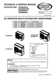
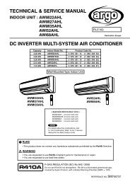
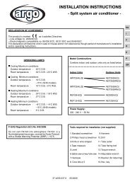
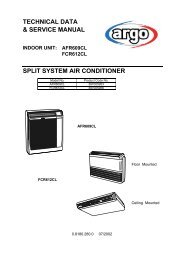
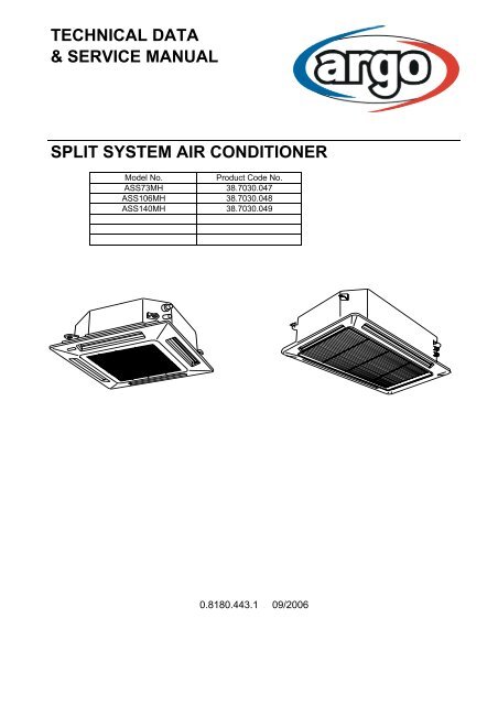
TECHNICAL DATA& SERVICE MANUALSPLIT SYSTEM AIR CONDITIONERModel No.Product Code No.ASS73MH 38.7030.047ASS106MH 38.7030.048ASS140MH38.7030.0490.8180.443.1 09/2006
IMPORTANT!Please read before installationThis <strong>air</strong> conditioning <strong>system</strong> meets strict safety and operatingstandards.For the installer or <strong>service</strong> person, it is important to install or<strong>service</strong> the <strong>system</strong> so that it operates safely and efficiently.For safe installation and trouble-free operation, you must:• Carefully read this instruction booklet before beginning.• Follow each installation or rep<strong>air</strong> step exactly as shown.• Observe all local, state and national electrical codes.• Pay close attention to all warning and caution notices given inthis <strong>manual</strong>.•The unit must be supplied with a dedicated electrical line.WARNINGThis symbol refers to a hazard or unsafe practice which can resultin severe personal injury or death.CAUTIONThis symbol refers to a hazard or unsafe practice which can resultin personal injury or product or property damage.If necessary, get helpThese instructions are all you need for most installation sites andmaintenance conditions.If you require help for a special problem, contact our sale/<strong>service</strong>outlet or your certified dealer for additional instructions.In case of improper installationThe manufacturer shall in no way be responsible for improperinstallation or maintenance <strong>service</strong>, including failure to follow theinstructions in this document.SPECIAL PRECAUTIONS• During installation, connect before the refrigerant <strong>system</strong> andthen the wiring one; proceed in the reverse orden when removingthe units.WARNING When wiringELECTRICAL SHOCK CAN CAUSE SEVEREPERSONAL INJURY OR DEATH. ONLY QUALIFIED,EXPERIENCED ELECTRICIANS SHOULD ATTEMPTTO WIRE THIS SYSTEM.• Do not supply power to the unit until all wiring and tubing arecompleted or reconnected and checked, to ensure the grounding.• Highly dangerous electrical voltages are used in this <strong>system</strong>.Carefully refer to the wiring diagram and these instructions whenwiring.Improper connections and inadequate grounding can causeaccidental injury and death.• Ground the unit following local electrical codes.• The Yellow/Green wire cannot be used for any connectiondifferent from the ground connection.• Connect all wiring tightly. Loose wiring may cause overheatingat connection points and a possible fire hazard.• Do not allow wiring to touch the refrigerant tubing, compressor,or any moving parts of the fan.• Do not use multi-core cable when wiring the power supply andcontrol lines. Use separate cables for each type of line.When transportingBe careful when picking up and moving the indoor and outdoorunits. Get a partner to help, and bend your knees when lifting toreduce strain on your back. Sharp edges or thin aluminium fins onthe <strong>air</strong> <strong>conditioner</strong> can cut your fingers.When installing...… In a ceilingMake sure the ceiling is strong enough to hold the unit-weight.It may be necessary to build a strong wooden or metal frame toprovide added support.… In a roomProperly insulate any tubing run inside a room to prevent"sweating", which can cause dripping and water damage towalls and floors.... In moist or uneven locationsUse a raised concrete base to provide a solid level foundationfor the outdoor unit. This prevents damage and abnormalvibrations.... In area with strong windsSecurely anchor the outdoor unit down with bolts and a metalframe. Provide a suitable <strong>air</strong> baffle.... In a snowy area (for heat pump-type <strong>system</strong>s)Install the outdoor unit on a raised platform that is higher thendrifting snow. Provide snow vents.When connecting refrigerant tubing• Keep all tubing runs as short as possible.• Use the flare method for connecting tubing.• Apply refrigerant lubricant to the matching surfaces of the flareand union tubes before connecting them; screw by hand andthen tighten the nut with a torque wrench for a leak-freeconnection.• Check carefully for leaks before starting the test run.NOTE:Depending on the <strong>system</strong> type, liquid and gas lines may be eithernarrow or wide. Therefore, to avoid confusion, the refrigeranttubing for your particular model is specified as narrow tube forliquid, wide tube for gas.When servicing• Turn the power OFF at the main power board before openingthe unit to check or rep<strong>air</strong> electrical parts and wiring.• Keep your fingers and clothing away from any moving parts.• Clean up the site after the work, remembering to check that nometal scraps or bits of wiring have been left inside the unit being<strong>service</strong>d.• Ventilate the room during the installation or testing the refrigeration<strong>system</strong>; make sure that, after the installation, no gas leaks arepresent, because this could produce toxic gas and dangerousif in contact with flames or heat-sources.2
Table of ContentsPage1. SPECIFICATIONS 41-1 Unit specifications 41-2 Major Component specifications 61-3 Other Component specifications 82. DIMENSIONAL DATA 93. ELECTRICAL DATA 113-1 Electric Wiring Diagram 113-2 Control PCB switches and functions 124. FUNCTION 134-1 Room Temperature Control 134-2 Automatic control for heating and cooling 145. REPLACING PCB 155-1 Replacing PCB 155-2 How to replace PCB 165-3 How to replace EEPROM with EEPROM included in PCB <strong>service</strong> pack 175-4 Table of setting 196. SERVICING AND MAINTENANCE FUNCTIONS 206-1 Indoor unit refrigerant noise countermeasures 206-2 Outdoor unit noise countermeasures: EEPROM 05 207. TROUBLE DIAGNOSIS 217-1 Contents of remote controller switch alarm display 217-2 Outdoor unit control panel led display 237-3 Trouble indications and inspection points 247-4 Remote controller servicing functions 267-5 Multiset alarm codes 277-6 Inspection of parts 503
1. SPECIFICATIONS1-1 Unit SpecificationsASS73MHPower sourceVoltage ratingPerformanceCapacityAir circulation (High/Med./Low)m³/h220 - 240V ~ 50Hz230VCoolingHeatingSee catalogue with the requested matching1140/1020/840FeaturesControls/Temperature controlsRemote Controller (Option)wiredwirelessFan speedAirflow directionAir FilterSound pressure level high/med/low dB(A)Refrigerant tubing connectionsRefrigerant Narrow tube mm(in.)tube diameter Wide tube mm(in.)RefrigerantRefrigerant controlDimensions & WeightDimensions (include panel) Unit Height mmWidthmmDepthmmMicroprocessor/ I.C. thermostatREM HW / REM HWSMREM HLFC/ASS / REM HL+RIC.A MURO3 and AutoAuto (Remote control)Washable56/54/50Flare type9,52 (3/8)15,88 (5/8)R410AElectronic expansion valve338860860<strong>Package</strong> dimensions Unit Height mmWidthmmDepthmmVolumem3Ceiling panel Height mmWidthmmDepthmmVolumem3Weight (include panel) Net kgShippingkgCeiling panel Net kgShippingkg3208808400,2381109659650,1222668DATA SUBJECT TO CHANGE WITHOUT NOTICE4
ASS106MH - ASS140MHPower sourceVoltage ratingPerformanceCapacityAir circulation (High/Med./Low)m³/h220 - 240V ~ 50Hz230VCoolingHeatingSee catalogue with the requested matching1920/1680/1320FeaturesControls/Temperature controlsRemote Controller (Option)wiredwirelessFan speedAirflow directionAir FilterSound pressure level high/med/low dB(A)Refrigerant tubing connectionsRefrigerant Narrow tube mm(in.)tube diameter Wide tube mm(in.)RefrigerantRefrigerant controlDimensions & WeightDimensions (include panel) Unit Height mmWidthmmDepthmmMicroprocessor/ I.C. thermostatREM HW / REM HWSMREM HLFC/ASS / REM HL+RIC.A MURO3 and AutoAuto (Remote control)Washable62/59/55Flare type9,52 (3/8)15,88 (5/8)R410AElectronic expansion valve3681150860<strong>Package</strong> dimensions Unit Height mmWidthmmDepthmmVolumem3Ceiling panel Height mmWidthmmDepthmmVolumem3Weight (include panel) Net kgShippingkgCeiling panel Net kgShippingkg35011708400,3511012509650,1312732810DATA SUBJECT TO CHANGE WITHOUT NOTICE5
1-2 Major Component SpecificationsASS73MHController PCBPart No.ControlsCR-CRP50A-BMicroprocessorFan & Fan MotorTypeQ'ty ……. Dia. and lenghtmmCentrifugal fan1…. Ø 443Fan motor model…Q'tyNo. Of poles…rpm (230 V, High)Running AmpsASFG6X-41D6P…16 … 4700,611Power inputW31,4Coil resistance (Ambient temp. 20 °C ) Ω BRN-WHT: 170,3WHT-VLT: 18,1VLT-ORG: 43,2ORG-YEL: 43,2WHT-PNK: 83,5YEL-BLK: 60,2Safety devicesTypeOperating temp. Open °CClose °CRun capacitor µFVACInternal thermal protector130 ± 879 ± 154,5440PanelModelFlap motorDew proof heaterratingrpmnominal outputcoil resistance (25°C)WkΩASG0025EM2LB24ZA12240 VAC2,5315,62 ± 15%240 V, 26WElectronic expansion valveCoilValve bodyUKV-U030EUKV-25D32Heat Exch. CoilCoilRowsFin pitchface areaAluminium plate fin / Copper tube2mm1,5m20,343DATA SUBJECT TO CHANGE WITHOUT NOTICE6
ASS106MH - ASS140MHController PCBPart No.ControlsCR-CRP50A-BMicroprocessorFan & Fan MotorTypeQ'ty ……. Dia. and lenghtFan motor model…Q'tyNo. Of poles…rpm (230 V, High/Med/Low/LowLow)Running AmpsAPower inputW38Coil resistance (Ambient temp. 20 °C ) Ω BRN-WHT: 75,1WHT-VLT: 6,7VLT-ORG: 20,6ORG-YEL: 27,4WHT-PNK: 42,7YEL-BLK: 58Safety devicesmmTypeOperating temp. Open °CClose °CRun capacitor µFVACCentrifugal fan1…. Ø 443SFG6X-81A6P…16 … 5300,765Internal thermal protector130 ± 879 ± 155440PanelModelFlap motorDew proof heaterratingrpmnominal outputcoil resistance (25°C)WkΩASG3648EM2LB24ZA12240 VAC2,5315,62 ± 15%240 V, 26WElectronic expansion valveCoilValve bodyUKV-U030EUKV-25D32Heat Exch. CoilCoilRowsFin pitchface areaAluminium plate fin / Copper tube2mm1,5m20,556DATA SUBJECT TO CHANGE WITHOUT NOTICE7
1-3 Other Component SpecificationsTrasformerRatingThermal cut-off temp.PrimarySecondary 1Secondary 2Secondary 3ATR-IIJ225AVAC 230V, 50HzAC 20V - 0.2AAC 14V - 0.3AAC 10,2V - 1.4A136°CThermistor ( Coil sensor E1, E2)ResistanceThermistor ( Coil sensor E3)ResistanceThermistor ( Room sensor TA, TF/BL)ResistancekΩkΩkΩPBC-41E-S260 °C 15,0 ± 5%PBC-41E-S42-20 °C 15,0 ± 4,42%DHKTEC-35-S85N25 °C 5,0 ± 4%Drain pumpModelRatingTotal head / capacitySafety float switchModelContact ratingVoltageInputWP20SL-21230V12W500 mm / 400 cc/min.FS-0218-102 (ASR425HG)FS-0218-103 (ASR436/448HG)DC 12V - 25W8
2. DIMENSIONAL DATAASS73MH1245261221776225812X-view10033971246 29223259157182X820 (Ceiling opening)566 (Suspention bolt pitch)377820 (Ceiling opening)757 (Suspention bolt pitch)Panel center368 253 412776308 301244812 1001286050028605001971242212Air intake grilleAir outletRefrigerant liquid line [D. 9.52 (In case of 25 type,use the tube connector.)]Refrigerant gas lineD. 12.7: 9, 12 typeDrain connectionPower supply entryFor discharge ductFor fresh <strong>air</strong> intake9 Suspension bolt mounting9
3. ELECTRICAL DATA3-1 Electric Wiring Diagram7P terminal board1(L) 2(N) U1 U2 R1 R2powersupplyinter-unitcontrolwiringremotecontroller11
3-2 Control PCB switches and functionsCR-TRP50A-BEMG (CN044)OC (CN040)VARISTOR(VA041)JP1DISP (CN072)EXCT (CN073) FILTER (JP001)(CN070)CHK (CN071)FAN DRIVEGRL(CN032) (CN020) T10 (CN061)POWER LED(D002)EEPROM(IC010)T10: 6 plug (yellow): used for remote control. (Refer to the remote control section)(CN061) 1- start/stop input 2- COM3- remote control prohibit/release input 4- start signal output5- COM (+DC12v) 6- alarm signal output T10EXCT:(CN073)DISP:(CN072)CHK:(CN071)JP1:(JP001)2P plug (red): Can be used for demand control. When imput is present, forces the unit to operatewith the termostat OFF.2P plug (white): Short-circuiting this plug allows the unit to be operated by the remote controller, even if it is notconnected to an outdoor unit. (In this case, alarm "E04", which indicates trouble in the serial communicationbetween the indoor and outdoor unit, does not occur.)2P plug (white): Test pin. Short-circuiting this pin allows the indoor FM (H fan speed), drain pump,flap motor (F1 position), and electronic expansion valve full-open position to checked. However this functionturns OFF if the indoor unit protection mechanism is activated. The unit can be operated even if the remotecontroller and outdoor unit are not connected. However even if the remote controller cannot is connected,it cannot be used to operate the unit. This function can be used for short-term tests.Jumper wire: Allows selection of the T10 terminal12
4. FUNCTIONS4-1 Room temperature control13
4-2 Automatic control for heating and cooling14
5. REPLACING PCB5-1 Replacing PCBAbout EEPROM(Erasable Programmable Read-Only Memory)EEPROM is a component in which the various information necessary for functionningcan be electronically written or erased. This component holds informationsthat is essential for the running of the unit, and must be handled with care.D002led lamp (red)15
5-2 How to replace PCB16
5-3 How to replace EEPROM with EEPROM included in PCB <strong>service</strong> pack17
5-4 Table of settings19
6. SERVICING AND MAINTENANCE FUNCTIONS20
7. TROUBLE DIAGNOSIS7-1 Contents of remote controller switch alarm display21
7-2 Outdoor unit control panel LED display23
7-3 Trouble indications and inspection points24
7-4 Remote controller servicing functions26
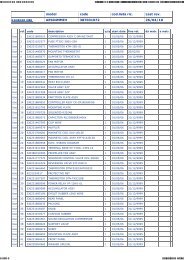
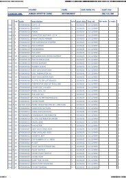
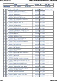
7-5 Multiset alarm codes27
7-6 Inspection of parts50
Via Varese, 90 - 21013 Gallarate - Va - ItalyTel. +39 0331 755111 - Fax +39 0331 776240www.argoclima.it