You also want an ePaper? Increase the reach of your titles
YUMPU automatically turns print PDFs into web optimized ePapers that Google loves.
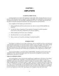
Figure 1-18.—Typical grid waveforms.Because the bias voltage is more negative than the signal voltage is positive, the resultant voltage(bias plus signal), E g , is ALWAYS negative. The signal, in this case, makes the grid voltage go eitherMORE or LESS NEGATIVE, (-9 to -3) but cannot drive it positive.Under these circumstances, the negative grid always repels electrons from the space charge. The gridcannot draw current. Any problems associated with grid current are eliminated, because grid currentcannot flow to a negative grid.You have probably already realized that the negative bias also reduces plate current flow. (Negativecharge on grid-less plate current, right?) The trick here is for the circuit designer to choose a bias and aninput signal that, when added together, do not allow the grid to become positive nor to become negativeenough to stop plate current.Tube biasing is very important. You will learn much more about it shortly. From this briefintroduction, you should have learned that grid bias·is a steady, direct voltage that in most cases makes the grid negative with respect to the cathode;·is in series with the signal voltage between grid and cathode;1-24