
Create successful ePaper yourself
Turn your PDF publications into a flip-book with our unique Google optimized e-Paper software.
CHAPTER 3<strong>BASIC</strong> <strong>METERS</strong>LEARNING OBJECTIVESUpon completing this chapter, you should be able to:1. Describe the basic theory of the galvanometer.2. Describe the basic theory of the D’Arsonval meter movement.3. State the proper procedure for connecting an ammeter to a circuit.4. Define ammeter sensitivity.5. State the proper procedure for connecting a voltmeter to a circuit.6. Describe possible effects on a circuit caused by the connection of a voltmeter.7. Define voltmeter sensitivity.8. Describe the internal operation of an ohmmeter with the use of a block diagram.9. Describe the operating procedure for using a megohmmeter.10. Describe the use of the electrodynamometer-type meter as a voltmeter, ammeter, and wattmeter.11. Describe the factors that limit wattmeter capability.12. Describe an open circuit, a ground, a short, and the tests used to check for these conditions.INTRODUCTIONWhen troubleshooting, testing, or repairing electronic equipment, you will use various meters andother types of test equipment to check for proper circuit voltages, currents, resistances, and to determine ifthe wiring is defective. You may be able to connect these test instruments to a circuit and take readingswithout knowing just how the instruments operate. However, to be a competent technician, you need to beable to do more than merely read a test instrument. You need a basic knowledge of how test instrumentsoperate. This chapter discusses the operating principles of some of the test instruments you will use inequipment troubleshooting.<strong>METERS</strong>The best and most expensive measuring instrument is of no use to you unless you know what you aremeasuring and what each reading indicates. Remember that the purpose of a meter is to measurequantities existing within a circuit. For this reason, when the meter is connected to the circuit, it must notchange the condition of the circuit.3-1
The movable coil is wrapped around the aluminum frame of the galvanometer. The coil is suspendedbetween the poles of the magnet by means of thin, flat ribbons of phosphor bronze. These ribbons providea conduction path for the current between the circuit being tested and the movable coil. The ribbons allowthe coil to twist in response to the interaction of the applied current through the coil and the magneticfield of the permanent magnet. They also provide the restoring force for the coil. Basically, the restoringforce is that force necessary to return the movable frame to its resting position after a reading. Theribbons restrain or provide a counterforce to the magnetic force acting on the coil. When the driving forceof the coil current is removed, the restoring force provided by the ribbons returns the coil to its zeroposition.Q-2. What physical component of a galvanometer provides the restoring force for the coil?To determine the amount of current flow, we must have a means to indicate the amount of coilrotation. Either of two methods may be used: (1) the POINTER arrangement or (2) the LIGHT ANDMIRROR arrangement.Q-3. In a galvanometer, what two methods are used to indicate the amount of coil rotation?In the pointer arrangement, one end of the pointer is mechanically connected to the rotating coil; asthe coil moves, the pointer also moves. The other end of the pointer moves across a graduated scale andindicates the amount of current flow. The overall simplicity of this arrangement is its main advantage.However, a disadvantage of this arrangement is that it introduces a mechanical coil balancing problem,especially if the pointer is long.Q-4. What is the primary disadvantage of the pointer arrangement for indicating coil rotation?In the light and mirror arrangement, the use of a mirror and a beam of light simplifies the problem ofcoil balance. When this arrangement is used to measure the turning of the coil, a small mirror is mountedon the supporting ribbon, as shown in figure 3-1. An internal light source is directed to the mirror andthen reflected to the scale of the meter. As the movable coil turns, so does the mirror. This causes the lightreflection to move across the graduated scale of the meter. The movement of the reflection is proportionalto the movement of the coil; therefore, the intensity of the current being measured by the meter isaccurately indicated.If the beam of light and mirror arrangement is used, the beam of light is swept to the right or leftacross a translucent screen (scale). The translucent screen is divided uniformly with the zero readinglocated at center scale. If the pointer arrangement is used, the pointer is moved in a horizontal plane to theright or left across a scale that is divided uniformly with the zero reading at the center. The direction inwhich the beam of light or the pointer moves depends on the direction (polarity) of current through thecoil.D’Arsonval Meter MovementMost dc instruments use meters based on some form of the D’Arsonval meter movement. InD’Arsonval-type meters, the length of the conductor and the strength of the field between the poles of themagnet are fixed. Therefore, any change in current causes a proportional change in the force acting on thecoil. Figure 3-2 is a simplified diagram showing the principle of the D’Arsonval movement.3-3
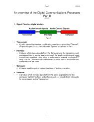
Figure 3-2.—D'Arsonval meter movement.In the figure, only one turn of wire is shown; however, in an actual meter movement, many turns offine wire would be used, each turn adding more effective length to the coil. The coil is wound on analuminum frame (bobbin) to which the pointer is attached. Oppositely wound hairsprings (only one isshown in the figure) are also attached to the bobbin, one at either end. The circuit to the coil is completedthrough the hairsprings. In addition to serving as conductors, the hairsprings serve as the restoring forcethat returns the pointer to the zero position when no current flows.Q-5. What component of the D’Arsonval meter movement completes the circuit for current flow to thecoil?COIL MOVEMENT.—As we discussed previously, the deflecting (moving) force on the coil isproportional to the current flowing through the coil. This deflecting force tends to cause the coil to rotateagainst the restraining force of the hairsprings. When the deflecting force and the restraining force areequal, the coil and the pointer stop moving. As we have just stated, the deflecting force is proportional tothe current in the coil, the angle (amount) of rotation is proportional to the deflecting force; therefore, theangle of rotation is proportional to the current through the coil. When current stops flowing through thecoil, the deflecting force stops, and the restoring force of the springs returns the pointer to the zeroposition.Q-6. What component supplies restoring force to the coil of the D’Arsonval meter movement?DIRECTION OF FORCE.—The current through the single turn of wire is in the directionindicated in the figure (away from you on the right-hand side and toward you on the left-hand side). If weapply the right-hand motor rule, the direction of force is upward on the left-hand side and downward onthe right-hand side; therefore, the direction of motion of the coil and pointer is clockwise. If the currentwere reversed in the wire, the direction of motion of the coil and pointer would be reversed. For a reviewof the right-hand rule for motors, refer to NEETS, Module 5, Introduction to Generators and Motors.PRINCIPLE OF OPERATION.—A more detailed view of the basic D'Arsonval movement, as it isused in ammeters and voltmeters, is shown in figure 3-3. The principle of operation is the same as thatdiscussed in the simplified version. The iron core is rigidly supported between the pole pieces; it serves to3-4
concentrate the flux in the narrow space between the iron core and the pole piece. Current flows into onehairspring, through the coil, and out the other hairspring. The restoring forces of the spiral springs returnthe pointer to the normal zero position when the current through the coil is interrupted. Conductorsconnect the hairsprings with the outside terminals of the meter. If the instrument is not DAMPED toabsorb the energy of the moving element, the pointer will oscillate (vibrate) for a period of time beforecoming to a stop in its final position. Damping is an energy-absorbing system that prevents this.Figure 3-3.—Detailed view of the basic D'Arsonval meter movement.DAMPING.—This is accomplished in many D'Arsonval movements by means of the motion of thealuminum bobbin on which the coil is wound. As the bobbin rotates in the magnetic field, anelectromotive force is induced into it as it cuts through the lines of force. Induced currents flow in thebobbin in a direction opposite to the motion; this causes the bobbin to go beyond its final position onlyonce before stopping. The overall sensitivity of the meter can be increased by the use of a lightweightrotating assembly (bobbin, coil, and pointer) and by the use of jewel bearings, as shown in figure 3-3.3-5
POLE CONSTRUCTION.—Note that the pole pieces in figures 3-2 and 3-3 have curved faces.You can see the advantage of this type of construction if you remember that lines of force enter and leavea magnetic field in the air gap at right angles to the coil, regardless of the angular position of the coil.Because of this type of construction, a more linear scale is possible than if the pole faces were flat.Q-7. What advantage is gained by using pole pieces with curved faces in the D’Arsonval metermovement?DC AMMETERThe movable coil of the D'Arsonval meter movement we have been discussing up to now uses smallsizewire in its windings. This small-size wire places limits on the amount of current that can be safelypassed through the coil. Therefore, the basic D'Arsonval movement discussed can be used to indicate ormeasure only very small currents. Certain circuit changes must be made to the basic D'Arsonval metermovement for it to be practical in everyday use. To measure large currents, you must use a SHUNT withthe meter.ShuntsA shunt is a physically large, low-resistance conductor connected in parallel (shunt) with the meterterminals. It is used to carry the majority of the load current. Such a shunt is designed with the correctamount of resistance so that only a small portion of the total current flows through the meter coil. Themeter current is proportional to the total load current. If the shunt is of such a value that the meter iscalibrated in milliamperes, the instrument is called a MILLIAMMETER. If the shunt has such a value thatthe meter must be calibrated in terms of amperes, it is called an AMMETER.Q-8. What structurally large, low-resistance conductor is connected in parallel with the metermovement to prevent damage?SHUNT RESISTANCE.—A single, standardized meter movement is normally used in allammeters, no matter what the range is for a particular meter. For example, meters with working ranges of0 to 10 amperes, 0 to 5 amperes, or 0 to 1 ampere all use the same meter movement. The various rangesare achieved through the use of different values of shunt resistance with the same meter movement. Thedesigner of the ammeter simply calculates the correct shunt resistance required to extend the range of themeter movement to measure any desired value of current. This shunt is then connected across the meterterminals. Shunts may be located inside the meter case (internal shunts) with the proper switchingarrangements for changing them. They may also be located outside the meter case (external shunts) withthe necessary leads to connect them to the meter.EXTERNAL SHUNTS.—An external-shunt circuit is shown in figure 3-4, view A. Typical externalshunts are shown in view B. View C shows a meter movement mounted within the case. The caseprovides protection against breakage, magnetic shielding in some cases, and portability.3-6
Figure 3-4.—Dc ammeter using the D'Arsonval movement with external shunts.SHUNT CONSTRUCTION.—The shunt strips (view B of figure 3-4) are usually made of the alloyManganin. Manganin has a temperature coefficient of almost zero. The zero-temperature coefficientproperty is desirable because of the heavy currents that often flow through shunts producing heat. A zerotemperaturecoefficient material is not affected by this heat; therefore, it remains stable in temperature.Most other materials increase their resistance as they are heated. If shunts were made of these materials,they would carry less current. More and more current would flow through the meter movement, and thechances of damage would increase. Using shunts constructed with zero-temperature coefficient materialseliminates this problem.Q-9. What type of temperature coefficient material does not produce increased heat in response toincreased current flow?The ends of the shunt strips are embedded in heavy copper blocks. The blocks are attached to themeter coil leads and the line terminals. To ensure accurate readings, you should not interchangeably usethe meter leads for a particular ammeter with those for a meter of a different range. Slight changes in leadlength and size may vary the resistance of the meter circuit. If this happens, current will also change andcause incorrect meter readings. External shunts are generally used where currents greater than 50 amperesmust be measured.SHUNT SELECTION.—When using an external-shunt ammeter, you should select a suitable shuntso that the scale deflection can be easily read. For example, if the scale has 150 divisions and the loadcurrent you want to measure is known to be between 50 and 100 amperes, a 150-ampere shunt would bethe correct choice. Under these conditions, each division of the scale represents 1 ampere. In other words,3-7
a full-scale deflection of the pointer would rest on the 150th division mark, indicating that 150 amperes ofload current is flowing. At half-scale deflection, the pointer would rest on the 75th division mark,indicating that 75 amperes of load current is flowing.A shunt having exactly the same current rating as the expected normal load current should never beselected. If you were to select such a shunt, higher than normal load currents could possibly drive thepointer off scale and damage the meter movement. A good choice of shunt values will place the indicatingneedle somewhere near the midscale indication when the load current you are reading is normal. Forexample, assume that the meter scale is divided into 100 equal divisions and you want to measure acurrent of 60 amperes. The shunt to use would be a 100-ampere shunt. This would make each division ofthe scale equal to 1 ampere. The meter indication would fall on the 60th division showing that 60 amperesof load current is flowing. Therefore, an allowance (40 amperes) remains for unexpected surge currents.Q-10. A good choice of shunt resistance will place the indicating pointer near what part of the meterscale with a normal load?INTERNAL SHUNTS FOR <strong>METERS</strong> IN THE 0- TO 50-AMPERE RANGE.—Whenmeasuring current ranges below 50 amperes, you will most often use internal shunts (R shunt ). In this way,you can easily change the range of the meter by means of a switching arrangement. A switch will selectthe correct internal shunt with the necessary current rating and resistance. Before you can calculate therequired resistance of the shunt for each range, the total resistance of the meter movement must beknown. For example, suppose you desire to use a 100-microampere D'Arsonval meter with an internalcoil resistance of 100 ohms to measure line currents up to 1 ampere. The meter will deflect to its full-scaleposition when the current through the deflection coil is 100 microamperes.Since the coil resistance is 100 ohms, you can calculate the coil's voltage (E coil ) by using Ohm's law,as follows:When the pointer is deflected to full scale, 100 microamperes of current flows through the coil and0.01 volt drops across it. Remember, 100 microamperes is the maximum safe current for this metermovement. Exceeding this value will damage the meter. The shunt must carry any additional load current.The meter coil has a 0.01 volt drop across it, and, because the shunt and coil are in parallel, the shuntalso has a voltage drop of 0.01 volt. The current that flows through the shunt is the difference between thefull-scale meter current and the line current being fed into the shunt. In this case, meter current is 100microamperes. Full-scale deflection is desired only when the total current is 1 ampere. Therefore, theshunt current must equal 1 ampere minus 100 microamperes, or 0.9999 ampere. Ohm's law is again usedto provide the approximate value of required shunt resistance (R shunt ), as follows:3-8
To increase the range of the 100-microampere meter to 1 ampere (full-scale deflection), place a 0.01-ohm shunt in parallel with the meter movement.You can convert the 100-microampere instrument to a 10-ampere meter by using a proper shunt. Thevoltage drop for a full-scale deflection is still 0.01 volt across the coil and the shunt. The meter current isstill 100 microamperes. The shunt current must therefore be 9.9999 amperes under full-scale deflection.Again, this is an approximate figure found by the application of Ohm’s law.You can also convert the same instrument to a 50-ampere meter by using the proper shunt resistance,as follows:INTERNAL SHUNTS FOR <strong>METERS</strong> IN THE MILLIAMPERE RANGE.—The above methodof computing the shunt resistance is satisfactory in most cases; however, it can only be used when the linecurrent is in the ampere range and the meter current is relatively small compared to the load current. Insuch cases, you can use an approximate value of resistance for the shunt, as was done above. However,when the line current is in the milliampere range and the coil current becomes an appreciable percentageof the line current, a more accurate calculation must be made. For example, suppose you desire to use ameter movement that has a full-scale deflection of 1 milliampere and a coil resistance of 50 ohms tomeasure currents up to 10 milliamperes. Using Ohm's law, you can figure the voltage (E coil ) across themeter coil (and the shunt) at full-scale deflection, as follows:The current that flows through the shunt (I shunt ) is the difference between the line current and themeter current, as figured below:The shunt resistance (R shunt ) may then be figured, as follows:Notice that, in this case, the exact value of shunt resistance has been used rather than anapproximation.3-9
The formula for determining the resistance of the shunt is given by Rs = I m /Is times R m , where R s isthe shunt resistance in ohms; I m is the meter current at full-scale deflection; Is is the shunt current at fullscaledeflection; and R m is the resistance of the meter coil. If the values given in the previous example areused in this equation, it will yield 5.55 ohms, the value previously calculated.SWITCHING SHUNT VALUES.—Various values of shunt resistance can be used, by means of asuitable switching arrangement, to increase the number of current ranges that can be covered by themeter. Two switching arrangements are shown in figure 3-5. View A is the simpler of the twoarrangements when a number of shunts are used to calculate the values of the shunt resistors. However, ithas two disadvantages:Figure 3-5.—Ways of connecting internal meter shunts.1. When the switch is moved from one shunt resistor to another, the shunt is momentarily removedfrom the meter. The line current then flows through the meter coil. Even a momentary surge ofcurrent could easily damage the coil.2. The contact resistance (resistance between the blades of the switch when they are in contact) is inseries with the shunt, but not with the meter coil. In shunts that must pass high currents, thiscontact resistance becomes an appreciable part of the total shunt resistance. Because the contactresistance is of a variable nature, the ammeter indication may not be accurate.The generally preferred method of range switching is shown in (figure 3-5, view B). Although onlytwo ranges are shown, as many ranges as needed can be used. In this type of circuit, the contact resistanceof the range-selector switch is external to the shunt and meter in each range position. The contactresistance in this case has no effect on the accuracy of the current measurement.Ammeter ConnectionsWhen you are using ammeters, a primary rule of safety is that such current-measuring instrumentsmust always be connected in series with a circuit, never in parallel with it. When an ammeter isconnected across a constant-potential source of appreciable voltage, the low internal resistance of themeter bypasses the circuit resistance. This results in the application of the source voltage (or a good3-10
portion of it) directly to the meter terminals. The resulting excessive current burns up the meter coil andrenders the meter useless until repaired.Q-11. In what manner are current-measuring instruments connected to a circuit?If you do not know the approximate value of current in the circuit, you should take a reading at thehighest range of the ammeter; then you should switch progressively to lower ranges until a suitablereading is obtained. Most ammeter scales indicate the current being measured in increasing values fromleft to right. If you connect the meter without observing proper polarity, the pointer may be deflectedbackwards (from right to left). This action often damages the meter movement. You should ensure thatthe ammeter is always connected so that the current will flow into the negative terminal and out thepositive terminal. Figure 3-6 shows various circuit arrangements and the proper ammeter connectionmethods to measure current in various portions of the circuit.Figure 3-6.—Proper ammeter connection.Q-12. An ammeter should always be connected so that current will flow into what terminal and out ofwhat terminal?Ammeter SensitivityAmmeter sensitivity is determined by the amount of current required by the meter coil to producefull-scale deflection of the pointer. The smaller the amount of current required to produce this deflection,the greater the sensitivity of the meter. A meter movement that requires only 100 microamperes for fullscaledeflection has a greater sensitivity than a meter movement that requires 1 milliampere for the samedeflection.Q-13. (True or False) The larger the current required to produce full-scale deflection of the meter coil,the better the sensitivity of the meter.Good sensitivity is especially important in ammeters to be used in circuits in which small currentsflow. As the meter is connected in series with the load, the current flows through the meter. If the internalresistance of the meter is a large portion of the load resistance, an effect known as METER-LOADINGwill occur. Meter-loading is the condition that exists when the insertion of a meter into a circuit changesthe operation of that circuit. This condition is not desirable. The purpose of inserting a meter into a circuitis to allow the measurement of circuit current in the normal operating condition. If the meter changes the3-11
circuit operation and changes the amount of current flow, the reading you obtain will be in error. Anexample of this is shown in figure 3-7.Figure 3-7.—Ammeter loading effect.Q-14. What condition exists when the insertion of a meter into a circuit changes the operation of thecircuit?In view A of figure 3-7, the circuit to be tested has an applied voltage of 100 millivolts and aresistance of 100 ohms. The current normally flowing in this circuit is 1 milliampere. In view B, anammeter that requires 1 milliampere for full-scale deflection and that has an internal resistance of 100ohms has been inserted. Since 1 milliampere of current flow is shown in view A, you might naturallyassume that with the meter inserted into the circuit, a full-scale deflection will occur. You might alsoassume that the 1 milliampere of circuit current will be measured. However, neither of these assumptionsis correct. With the ammeter inserted into the circuit, as shown in view B, the total resistance of the circuitis 200 ohms. With an applied voltage of 100 millivolts, applying Ohm’s law shows the actual current(I circuit ) to be 0.5 milliampere.Since the meter reads 0.5 milliampere instead of the normal value of current, the meter reveals that adefinite loading effect has taken place. In cases such as this, the use of ammeters, which have a lowerinternal resistance and a better current sensitivity, is desirable.DC VOLTMETERUp to this point, we have been discussing the 100-microampere D’Arsonval movement and its use asan ammeter. However, it can also be used to measure voltage if a MULTIPLIER (high resistance) isplaced in series with the moving coil of the meter. For low-voltage instruments, this resistance isphysically mounted inside the meter case with the D’Arsonval movement. The series resistance isconstructed of a wire-wound resistance that has a low temperature coefficient wound on either a spool or3-12
card frame. For high-voltage ranges, the series resistance can be connected externally. A simplifieddiagram of a voltmeter is shown in figure 3-8.Figure 3-8.—Internal construction and circuit of a simplified voltmeter.Q-15. What modification is made to the D’Arsonval meter movement to enable the meter to measurevoltage?Keep in mind that the D’Arsonval meter movement uses current flow to produce a magnetic field thatis proportional to the current. The meter movement is, therefore, an indicator of current flow rather thanvoltage. The addition of the series resistance is what allows the meter to be calibrated in terms of voltage;that is, the meter movement of a voltmeter operates because of the current flow through the meter, but thescale is marked in volts. For example, the meter movement shown in figure 3-9 has an internal resistanceof 100 ohms, requires 100 microamperes for full-scale deflection, and has a voltage drop of 10 millivoltswhen full-scale deflection is reached. If you were to place this meter directly across a 10-volt source, anexcessive current (in milliamperes) would flow. The meter would be destroyed because of the excessivecurrent flowing through the meter movement. This can be seen in the following Ohm’s law application:Figure 3-9.—Use of multiplier resistors with D'Arsonval meter movement.Using this equation, you can see that a current through the meter of 100 milliamperes is excessiveand will cause damage.3-13
Since the normal voltage drop for the meter is 10 millivolts at full-scale deflection, some means mustbe supplied to drop the extra 9.99 volts without applying it directly to the meter. This is done by theaddition of a multiplier resistor, as shown in figure 3-9.Extending Voltmeter RangesThe value of series resistance is determined by the current required for full-scale deflection and bythe range of the voltages to be measured. Since the current through the meter circuit is directlyproportional to the applied voltage, the meter scale can be calibrated directly in volts for a fixed value ofseries resistance. For example, let’s assume that the basic meter is to be made into a voltmeter with a fullscaledeflection of 1 volt. The coil resistance of the basic meter is 100 ohms, and 100 microamperes ofcurrent causes full-scale deflection. The resistance (R meter) required to limit the total current in the circuitto 100 microamperes can be found as follows:Because the meter coil already measures 100 ohms, the series resistance required is equal to 10kilohms minus 100 ohms, or 9.9 kilohms.Q-16. What factors determine the value of the multiplier resistor?Multirange voltmeters use one meter movement. The required resistances are connected in serieswith the meter by a switching arrangement. A schematic diagram of a multirange voltmeter with threeranges is shown in figure 3-10. The total meter resistance (R meter ) for each of the three ranges, beginningwith the 1-volt range, is figured by the application of Ohm’s law, as follows:3-14
Figure 3-10.—Multirange voltmeter.The actual value of the multiplying series resistor (R series ) for each of these circuits is 100 ohms lessthan the total resistance. This allows for the resistance of the meter coil (R coil ).Voltmeter Circuit ConnectionsWhen voltmeters are used, a primary rule of safety is that such voltage-measuring instruments mustalways be connected in parallel with (across) a circuit. If you are unsure of the level of the voltage to bemeasured, take a reading at the highest range of the voltmeter and progressively (step by step) lower therange until a suitable reading is obtained. In many cases, the voltmeter you will be using will not be a3-15
center-zero- (0 reading is in the center) indicating instrument. Observing the correct polarity is importantwhen connecting the instrument to the circuit. Voltmeter polarity is the same as for the dc ammeter; thatis, current flows from negative to positive.Q-17. In what manner are voltage-measuring instruments connected to the circuit to be measured?Influence of a Voltmeter in a CircuitThe purpose of a voltmeter is to indicate the potential difference between two points in a circuit.When a voltmeter is connected across a circuit, it shunts the circuit. If the voltmeter has a low resistance,it will draw a substantial amount of current. This action lowers the effective resistance of the circuit andchanges the voltage reading. When you are making voltage measurements in high-resistance circuits, usea HIGH-RESISTANCE VOLTMETER to prevent the shunting action of the voltmeter. The effect is lessnoticeable in low-resistance circuits because the shunting effect is less. The problem of voltmetershunting (sometimes called circuit loading) is illustrated in figure 3-11.Figure 3-11.—Shunting action caused by a voltmeter.Q-18. When making voltage measurements in a high-resistance circuit, you should always use avoltmeter with what relative value of resistance?In view A of figure 3-11, a source of 150 volts is applied to a series circuit consisting of two 10-kilohm resistors. View A shows the voltage drop across each resistor to be 75 volts. In the 150-volt range,the voltmeter to be used has a total internal resistance of 10 kilohms. View B shows the voltmeterconnected across the circuit. The parallel combination of R2 and the meter now present a total resistanceof 5 kilohms. Because of the addition of the voltmeter, the voltage drops change to 100 volts across R1and 50 volts across R2. Notice that this is not the normal voltage drop across R2. Actual circuit conditionshave been altered because of the voltmeter.Voltmeter SensitivityThe sensitivity of a voltmeter is given in ohms per volt. It is determined by dividing the sum of theresistance of the meter (R meter ), plus the series resistance (R series ), by the full-scale reading in volts. Inequation form, sensitivity is expressed as follows:This is the same as saying the sensitivity is equal to the reciprocal of the full-scale deflection current.In equation form, this is expressed as follows:3-16
Therefore, the sensitivity of a 100-microampere movement is the reciprocal of 0.0001 ampere, or10,000 ohms per volt.Q-19. What term is used to express the sensitivity of a voltmeter?<strong>METERS</strong> USED FOR MEASURING RESISTANCEThe two instruments you will use most often to check continuity, or to measure the resistance of acircuit or circuit component, are the OHMMETER and the MEGGER (MEGOHMMETER). Theohmmeter is widely used to measure resistance and to check the continuity of electrical circuits anddevices. Its range usually extends to only a few megohms. The megger is widely used for measuringinsulation resistance, such as that between a wire and the outer surface of its insulation, and the insulationresistance of cables and insulators. The range of a megger can be extended to more than 1,000 megohms.Q-20. What instrument is used for measuring the insulation resistance of cables?The OhmmeterA simple ohmmeter circuit is shown in figure 3-12. The ohmmeter consists of the dc milliammeter,discussed earlier in this chapter, and the added features shown below:3-17
Figure 3-12.—Simple ohmmeter circuit.• A source of dc potential; and• One or more resistors (one of which is variable).Q-21. What added features enable a dc milliammeter to function as an ohmmeter?The deflection of the pointer of an ohmmeter is controlled by the amount of battery current passingthrough the moving coil. Before you can measure the resistance of an unknown resistor or electricalcircuit, you must calibrate the ohmmeter to be used. If the value of resistance to be measured can beestimated within reasonable limits, select a range on the ohmmeter that will give approximately half-scaledeflection when the resistance is inserted between the probes. If you cannot estimate the resistance to bemeasured, then set the range switch on the highest scale. Whatever range you select, the meter must becalibrated to read zero before the unknown resistance is measured.To calibrate the meter, you first short the test leads together, as shown in figure 3-12. With the testleads shorted, a complete series circuit exists. The complete series circuit consists of the 3-volt source, theresistance of the meter coil (R meter), the resistance of the zero-adjust rheostat, and the series multiplyingresistor (R series ). The shorted test leads cause current to flow and the meter pointer to deflect.Notice that the zero point on the ohmmeter scale (as opposed to the zero points for voltage andcurrent) is located at the extreme right side of the scale. With the test leads shorted, the zero-adjustpotentiometer is set so that the pointer rests on the zero mark. Therefore, a full-scale deflection indicateszero resistance between the leads.Q-22. A full-scale deflection on an ohmmeter scale indicates what resistance between the leads?If you change the range on the meter, you must "zero" (calibrate) the meter again to obtain anaccurate reading. When you separate the test leads, the pointer of the meter will return to the left side ofthe scale. This action, as explained earlier, is caused by the restoring force of the spring tension acting onthe movable coil assembly. The reading at the left side of the scale indicates an infinite resistance.3-18
After you have adjusted the ohmmeter for zero reading, it is ready to be connected to a circuit tomeasure resistance. A typical circuit and ohmmeter arrangement is shown in figure 3-13. You mustensure that the power switch of the circuit to be measured is in the de-energized (OFF) position. Thisprevents the source voltage of the circuit from being applied to the meter, a condition that could causesevere damage to the meter movement.Figure 3-13.—Measuring circuit resistance with an ohmmeter.Remember that the ohmmeter is an open circuit when the test leads are separated. To take aresistance reading with a meter, you must provide a path for current flow produced by the meter’s battery.In view A of figure 3-13, the meter is connected at points A and B to produce this path. Connecting thesetest leads places resistors R1 and R2 in series with the resistance of the meter coil, the zero-adjustpotentiometer, and the series multiplying resistor. Since you previously calibrated the meter, the amountof coil movement now depends only on the resistances of R1 and R2.The addition of R1 and R2 into the meter circuit raises the total series resistance and decreases thecurrent. This decreases the amount of pointer deflection. The pointer comes to rest at a scale reading thatindicates the combined resistance of R1 and R2. If you were to replace either R1 or R2, or both, with aresistor having a larger ohmic value, the current flow in the moving coil of the meter would be decreasedeven more. This would further decrease the pointer deflection, and the scale indication would read a stillhigher circuit resistance. View B is a simplified version of the circuitry in view A.From our ohmmeter discussion, two facts should be apparent: (1) Movement of the moving coil isproportional to the amount of current flow, and (2) the scale reading of the ohmmeter is inverselyproportional to current flow in the moving coil.The amount of circuit resistance to be measured may vary over a wide range. In some cases, it mayonly be a few ohms; in other cases, it may be as great as 1 megohm. Scale multiplication features are builtinto most ohmmeters so that they will indicate any ohmic value being measured and offer the leastamount of error. Most ohmmeters are equipped with a selector switch for selecting the multiplicationscale desired. For example, view A of figure 3-14 shows a typical meter that has a six-position switch.The positions are marked on the meter in multiples of 10, from R × 1 through R × 100K.3-19
Figure 3-14.—Ohmmeter with multiplication switch.The range used to measure any particular unknown resistance (R x in view A of figure 3-14) dependson the approximate ohmic value of the unknown resistance. For instance, the ohmmeter scale of the figureis calibrated in divisions from 0 to infinity. Note that the divisions are easier to read on the right-handportion of the scale than on the left. For this reason, if R x is greater than 1,000 ohms and if you are usingthe R × 1 range, you will be unable to accurately read the indicated resistance. This happens because thecombined series resistance of resistors R x is too large for range R × 1 to allow enough battery current toflow to deflect the pointer away from infinity. You need to turn the range switch to the R × 10 position toobtain the 1,000-ohm reading.Let’s assume that you have changed the range switch to the R × 10 position and the pointer nowdeflects to a reading of 375 ohms, as shown in view B of figure 3-14. This would indicate to you thatunknown resistance R x has 3,750 (375 times 10) ohms of resistance. The change of range caused thedeflection because resistor R × 10 has only 1/10 the resistance of resistor R × 1. Therefore, selecting thesmaller series resistance allowed a battery current of sufficient value to cause a readable pointerdeflection. If the R × 100 range were used to measure the same 3,750 ohm resistor, the pointer woulddeflect still further to the 37.5-ohm position, as shown in view C. This increased deflection would occurbecause resistor R × 100 has only 1/10 the resistance of resistor R × 10.Q-23. The R × 100 resistance selection on an ohmmeter has what amount of resistance compared to theR × 10 selection?The circuit arrangement in view A of figure 3-14 allows the same amount of current to flow throughthe moving meter coil. The same amount is allowed to flow whether the meter measures 10,000 ohms onthe R × 1 scale, 100,000 ohms on the R × 10 scale, or 1,000,000 ohms on the R × 100 scale.3-20
The same amount of current must always be used to deflect the pointer to a certain position on thescale (midscale position, for example), regardless of the multiplication factor being used. Since themultiplier resistors are of different values, you must always "zero" the meter for each multiplication scaleselected. When selecting a range on the ohmmeter, select the one that will result in the pointer coming torest as close to the midpoint of the scale as possible. This will enable you to read the resistance moreaccurately because scale readings are more easily interpreted at or near midpoint.The MegohmmeterAn ordinary ohmmeter cannot be used for measuring multimillion ohm values of resistances, such asthose in conductor insulation. To test for such insulation breakdown, you need to use a much higherpotential than that supplied by the battery of an ohmmeter. This potential is placed between the conductorand the outside of the insulation. A megger (megohmmeter) is used for these tests. The megger, shown infigure 3-15, is a portable instrument consisting of two main elements: (1) a hand-driven dc generator,which supplies the necessary voltage for making the measurement, and (2) the instrument portion, whichindicates the value of the resistance you are measuring. The instrument portion is of the opposed-coiltype, as shown in view A. Coils a and b are mounted on movable member c. A fixed angular relationshipexists between coils, and they are free to turn as a unit in a magnetic field. Coil b tends to move thepointer counterclockwise, and coil a tends to move it clockwise.Figure 3-15.—Megger internal circuit and external view.Coil a is connected in series with R3 and unknown resistance R x . The combination of coil a, R3, andR x forms a direct series path between the + and − brushes of the dc generator. Coil b is connected in serieswith R2, and this combination is also connected across the generator. Notice that the movable member(pointer) of the instrument portion of the megger has no restoring springs. Therefore, when the generatoris not being operated, the pointer will float freely and may come to rest at any position on the scale.3-21
to the right. Since the frequencies you will be measuring are 60 hertz or greater, the meter is incapable ofmechanically responding at this speed. The result is simply a vibration near the zero point; in addition, nouseful reading of voltage or current is obtained. This problem does not exist with theelectrodynamometer-type movement. Current flow through the stationary (fixed) coils sets up a magneticfield. Current flow through the moving coils sets up an opposing magnetic field. With two magnetic fieldsopposing, the pointer deflects to the right. If the current reverses direction, the magnetic fields of both setsof coils will be reversed. With both fields reversed, the coils still oppose each other, and the pointer stilldeflects to the right. Therefore, no rectifying devices are required to enable the electrodynamometer metermovement to read both ac and dc. Rectifying devices are required for the D’Arsonval-type metermovement to enable it to be used for measuring ac voltages and currents.Q-29. What is the primary advantage of the electrodynamometer-type meter over the D’Arsonval-typemeter?VOLTMETERWhen an electrodynamometer is used as a voltmeter, no problems in construction are encounteredbecause the current required is not more than 0.1 ampere. This amount of current can be handled easily bythe spiral springs. When the electrodynamometer is used as a voltmeter, its internal connections andconstruction are as shown in view A of figure 3-17. Fixed coils a and b are wound of fine wire since thecurrent flow through them will not exceed 0.1 ampere. They are connected directly in series with movablecoil c and the series current-limiting resistor.Figure 3-17.—Circuit arrangement of electrodynamometer for use as a voltmeter and an ammeter.3-24
impressed on the voltage circuit, current is proportional to and in phase with the line voltage. Figure 3-19shows the proper way to connect a wattmeter into a circuit.Figure 3-19.—Wattmeter connection.Wattmeter ErrorsElectrodynamic wattmeters are subject to errors arising from such factors as temperature andfrequency. For example, heat through the coils eventually causes the small springs attached to the pointerto lengthen and lose tension, which produces deflection errors. Large currents through the wattmeter alsoproduce a noticeable deflection error. These errors are caused by the heat (I 2 R) loss through coils from theapplication of high currents. Because of this, the maximum current range of electrodynamic wattmeters isnormally restricted to approximately 20 amperes. The voltage range of wattmeters is usually limited toseveral hundred volts because of heat dissipation within the voltage circuit. However, the voltage rangecan be extended by the use of voltage multipliers.Good-quality, portable wattmeters usually have an accuracy of 0.2 to 0.25 percent. You mustremember, though, that electrodynamic wattmeter errors increase with frequency. For the higherfrequency and power ranges, special types of wattmeters are made specifically for those ranges. We willdiscuss two such wattmeters in chapter 5 of this module.Wattmeter OverloadsThe wattmeter consists of two circuits, either of which will be damaged if too much current passesthrough them. You should be especially aware of this fact because the reading on the instrument will nottell you whether or not the coils are being overheated. If an ammeter or voltmeter is overloaded, thepointer will indicate beyond the upper limit of its scale. In the wattmeter, both the current and potentialcircuit may carry such an overload that their insulations burn; yet the pointer may be only part of the wayup the scale. This is because the position of the pointer depends upon the power factor of the circuit aswell as upon the voltage and current. Therefore, a low power-factor circuit will provide a very lowreading on the wattmeter. The reading will be low, even when the current and voltage circuits are loadedto the maximum safe limit. The safe rating for each wattmeter is always distinctly rated, not in watts, butin volts and amperes.3-26
TECHNIQUES FOR METER USEWe have considered the more common meters; now let’s consider some of the techniques employedin their use. The techniques suggested here are not all-inclusive. You will find, as you develop yourtechnical skills, other variations and techniques in use. Consider the techniques for measuring current in acircuit. You can accomplish this by placing an ammeter in series with the circuit or by measuring thevoltage across a resistor of known value and using Ohm’s law to figure current. This last technique has theadvantage of eliminating the necessity of opening the circuit to connect the ammeter.CONTINUITY TESTSOpen circuits are those in which the flow of current is interrupted by a broken wire, defective switch,or any means by which the current cannot flow. The test used to detect open circuits (or to see if thecircuit is complete or continuous) is continuity testing.An ohmmeter (which contains its own batteries) is excellent for use in a continuity test. Normally,continuity tests are performed in circuits where the resistance is very low, such as the resistance of acopper conductor. An open is indicated in these circuits by a very high or infinite resistance between twocontinuously connected points.Figure 3-20 shows a continuity test of a cable that connects two electronic units. Notice that bothplugs are disconnected and the ohmmeter is in series with conductor D under test. The power should beoff. When checking conductors A, B, and C (connection of ohmmeter to conductors not shown), thecurrent from the ohmmeter flows through plug 2 (female) through conductor A, B, or C to plug 1(female). From plug 1, current passes through the jumper to the chassis, which is "grounded" to the ship’sstructure. The metal structure serves as the return path to the chassis of unit 2 and completes the circuitthrough the series-connected ohmmeter. The ohmmeter indicates a low resistance because no break existsin conductors A, B, or C. However, checking conductor D reveals an open. The ohmmeter is shownindicating maximum resistance because current cannot flow in an open circuit. With an open circuit, theohmmeter needle is all the way to the left since it is a series-type ohmmeter (reads right to left).Figure 3-20.—Continuity test.3-27
Where conditions are such that the ship’s structure cannot be used as the return path, one of the otherconductors (known to be good) may be used. For example, to check D, you can connect a jumper frompin D to pin A of plug 1 (female) and the ohmmeter leads to pins D and A of plug 2 (female). Thistechnique will also reveal the open in the circuit.TESTING FOR GROUNDSGrounded circuits are caused by some conducting part of the circuit making contact either directly orindirectly with the metallic structure of the ship. Grounds can have many causes. The two most commonare the fraying of insulation from a wire and moisture-soaked insulation. The fraying of insulation from awire allows bare wire to come into contact with the metal ground. Moisture-soaked insulation causesreduced insulation resistance (also classified as a ground).Grounds are usually indicated by blown fuses or tripped circuit breakers. Blown fuses or trippedcircuit breakers, however, can also result from a short circuit other than a ground. A high-resistanceground can also occur when current is increased significantly but not enough to rupture the fuse or trip thecircuit breaker.CAUTIONBefore testing any circuit, ensure the circuit under test has been de-energizedand checked with a safety shorting probe.In testing for grounds, you may use a megger or an ohmmeter. Measuring the resistance to groundfrom points in a circuit determines if the point is grounded. Referring again to figure 3-20, you can seeone possible means of testing a cable for grounds. If the jumper is removed from pin D of plug 1 (female),a test for ground can be made for each conductor in the cable. You can do this by connecting one meterlead to ground and the other to each of the pins of either of the plugs. A low resistance indicates that somepart of that conductor or one of the plug assemblies is grounded. Both plugs must be removed from theirunits; if only one plug is removed, a false indication is possible because a conductor may be groundedthrough the unit.TESTING FOR SHORTSA short circuit, other than a grounded one, is one where two conductors touch each other directly orthrough another conducting element. Two conductors with frayed insulation may touch and cause a short.Too much solder on the pin of a connector may short to the adjacent pin. In a short circuit, enough currentmay or may not flow to blow a fuse or open a circuit breaker. A short may occur between two cablescarrying signals but might not be indicated by a blown fuse.Shorts occur in many components, such as transformers, motor windings, and capacitors. The majortest method used to detect shorts in such components is to measure resistance. The indicated resistance isthen compared with the resistance given on schematics or in the equipment technical manuals todetermine whether the measured value is within specifications.An ohmmeter is the device used to check for shorts. You can use the ohmmeter to detect a shortbetween two conductors by measuring the resistance between them (be sure electrical power has beendisconnected). A low resistance reading indicates a short. You can test the circuit in figure 3-20 for ashort by first removing the jumper and disconnecting both plugs; you then measure the resistance betweenthe two suspended conductors.3-28
connected in parallel with the circuit to be measured, the internal meter circuitry is electrically connectedin series.In making resistance tests, take into account that other circuits containing resistances andcapacitances may be in parallel with the circuit to be measured. Erroneous conclusions may be drawnfrom readings obtained in such cases. Remember, a capacitor blocks the dc flow from the ohmmeter. Toobtain an accurate reading when other parts are connected across the suspected circuit, disconnect one endof the circuit to be measured from the equipment. For example, many of the resistors in majorcomponents and subassemblies are connected across transformer windings. To obtain a valid resistancemeasurement, you must isolate the resistors to be measured from the shunt resistances of the coils of thetransformers.Resistance tests are also used to check a component for grounds. In these tests, the component to betested should be disconnected from the rest of the circuit so that no normal circuit ground will exist.Dismounting the component to be checked is not necessary. The ohmmeter is set for a high-resistancerange. Then the ohmmeter is connected between ground and each electrically separate circuit of thecomponent being tested. Any resistance reading less than infinity indicates at least a partial ground. Youcan also check capacitors suspected of being short-circuited by measuring the resistance. To check acapacitor suspected of being open, temporarily shunt a known good capacitor then recheck theperformance of the circuit.CAUTIONTo avoid possible damage to equipment during resistance tests, observe thefollowing precautions:• Always connect an ammeter in series—never in parallel.• Connect a voltmeter in parallel.• Never connect an ohmmeter to a live circuit.• Observe polarity when using a dc ammeter or a dc voltmeter.• View meters directly from the front. When viewed from an angle off to the side, an incorrectreading will result because of OPTICAL PARALLAX. (Parallax was covered in NEETS, Module3, Introduction to Circuit Protection, Control, and Measurement.)• Always choose an instrument suitable for the measurement desired.• Select the highest range first and then switch to the proper range.• In using a meter, choose a scale that will result in an indication as near midscale as possible.• Do not mount or use instruments in the presence of a strong magnetic field.• Remember, a low internal resistance voltmeter (low sensitivity) may shunt the circuit beingmeasured and result in incorrect readings.3-30
SUMMARYThe important points of this chapter are summarized in the following paragraphs. You should befamiliar with these points before continuing with your study of test equipment.A permanent-magnet, moving-coil meter movement (D’ARSONVAL movement) uses theinteraction of magnetic fields to produce movement.DAMPING is used to smooth out the vibration and to help prevent overshooting of the meterpointer.ELECTRODYNAMOMETER movements are usually used in wattmeters. They operate much likethe D’Arsonval meter movement, except field coils are used instead of a permanent magnet.Electrodynamometer movements measure either ac or dc without the use of a rectifier.3-31
A SHUNT is a physically large, low-resistance conductor connected in parallel with the meterterminals. It carries the majority of the load current so that only a small portion of the total current willflow through the meter coil.An AMMETER measures current and is always connected in series with the circuit being measured.An ammeter should have a low resistance so that the effect of the ammeter on the circuit will be kept to aminimum.VOLT<strong>METERS</strong> are used to measure voltage and are always connected in parallel with the circuitbeing measured. A voltmeter should have a high resistance compared to the circuit being measured tominimize the loading effect. Voltmeter sensitivity is expressed in ohms per volt.OHM<strong>METERS</strong> are used to measure resistance and to check continuity. An ohmmeter is electricallyconnected in series with the resistance being measured. The ohmmeter range, which allows a midscaledeflection, should be used.A MEGOHMMETER (MEGGER) is used to measure very high resistance, such as the insulationof wiring.A WATTMETER is usually an electrodynamometer and is used to measure power.3-32
A CONTINUITY TEST is accomplished with an ohmmeter. This test is used to check for opens (orto see if the circuit is complete or continuous).GROUNDED CIRCUITS are caused by some conducting part of the circuit making contact eitherdirectly or indirectly with the metallic structure of the ship or chassis. In testing for grounds, you may useeither an ohmmeter or a megger.A SHORT CIRCUIT, other than a grounded one, is where two conductors touch each other directlyor through another conducting element. An ohmmeter is used to test for shorts.ANSWERS TO QUESTIONS Q1. THROUGH Q29.A-1. Self-excited.A-2. Phosphor bronze ribbons.A-3. The pointer arrangement and the light and mirror arrangement.A-4. Coil balance.A-5. Hairspring.A-6. Hairspring.A-7. Makes it possible to have a more linear scale than if the poles were flat.A-8. Shunt.A-9. Zero-temperature coefficient.A-10. Midscale.A-11. In series.A-12. Negative, positive.3-33
A-13. False.A-14. Meter-loading.A-15. A multimeter (high resistance) is placed in series with the coil of the meter.A-16. The current required for full-scale deflection, and the range of the voltage to be measured.A-17. In parallel.A-18. High.A-19. Ohms per volt.A-20. Megohmmeter (megger).A-21. 1. A source of dc potential. 2. One or more resistors (one of which is variable).A-22. Zero.A-23. 1/10.A-24. Shunts leakage current, which prevents false readings.A-25. 500.A-26. Friction clutches.A-27. Fixed coils.A-28. Size of spiral conducting.A-29. The electrodynamometer-type meter can be used to measure both ac and dc currents.3-34