
Create successful ePaper yourself
Turn your PDF publications into a flip-book with our unique Google optimized e-Paper software.
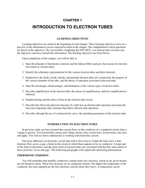
CHAPTER 1<strong>INTRODUCTION</strong> <strong>TO</strong> <strong>ELECTRON</strong> <strong>TUBES</strong>LEARNING OBJECTIVESLearning objectives are stated at the beginning of each chapter. These learning objectives serve as apreview of the information you are expected to learn in the chapter. The comprehensive check questionsare based on the objectives. By successfully completing the OCC/ECC, you indicate that you have metthe objectives and have learned the information. The learning objectives are listed below.Upon completion of this chapter, you will be able to:1. State the principle of thermionic emission and the Edison Effect and give the reasons for electronmovement in vacuum tubes.2. Identify the schematic representation for the various electron tubes and their elements.3. Explain how the diode, triode, tetrode, and pentode electron tubes are constructed, the purpose ofthe various elements of the tube, and the theory of operation associated with each tube.4. State the advantages, disadvantages, and limitations of the various types of electron tubes.5. Describe amplification in the electron tube, the classes of amplification, and how amplification isobtained.6. Explain biasing and the effect of bias in the electron tube circuit.7. Describe the effects the physical structure of a tube has on electron tube operation and name thefour most important tube constants that affect efficient tube operation.8. Describe, through the use of a characteristic curve, the operating parameters of the electron tube.<strong>INTRODUCTION</strong> <strong>TO</strong> <strong>ELECTRON</strong> <strong>TUBES</strong>In previous study you have learned that current flows in the conductor of a completed circuit when avoltage is present. You learned that current and voltage always obey certain laws. In electronics, the lawsstill apply. You will use them continuously in working with electronic circuits.One basic difference in electronic circuits that will at first seem to violate the basic laws is thatelectrons flow across a gap, a break in the circuit in which there appears to be no conductor. A large partof the field of electronics and the entire field of electron tubes are concerned with the flow and control ofthese electrons "across the gap." The following paragraphs will explain this interesting phenomenon.THERMIONIC EMISSIONYou will remember that metallic conductors contain many free electrons, which at any given instantare not bound to atoms. These free electrons are in continuous motion. The higher the temperature of theconductor, the more agitated are the free electrons, and the faster they move. A temperature can be1-1
eached where some of the free electrons become so agitated that they actually escape from the conductor.They "boil" from the conductor's surface. The process is similar to steam leaving the surface of boilingwater.Heating a conductor to a temperature sufficiently high causing the conductor to give off electrons iscalled THERMIONIC EMISSION. The idea of electrons leaving the surface is shown in figure 1-1.Figure 1-1.—Thermionic emission.Thomas Edison discovered the principle of thermionic emission as he looked for ways to keep sootfrom clouding his incandescent light bulb. Edison placed a metal plate inside his bulb along with thenormal filament. He left a gap, a space, between the filament and the plate. He then placed a battery inseries between the plate and the filament, with the positive side toward the plate and the negative sidetoward the filament. This circuit is shown in figure 1-2.1-2
Figure 1-2.—Edison's experimental circuit.When Edison connected the filament battery and allowed the filament to heat until it glowed, hediscovered that the ammeter in the filament-plate circuit had deflected and remained deflected. Hereasoned that an electrical current must be flowing in the circuit—EVEN ACROSS THE GAP betweenthe filament and plate.Edison could not explain exactly what was happening. At that time, he probably knew less aboutwhat makes up an electric circuit than you do now. Because it did not eliminate the soot problem, he didlittle with this discovery. However, he did patent the incandescent light bulb and made it available to thescientific community.Let's analyze the circuit in figure 1-2. You probably already have a good idea of how the circuitworks. The heated filament causes electrons to boil from its surface. The battery in the filament-platecircuit places a POSITIVE charge on the plate (because the plate is connected to the positive side of thebattery). The electrons (negative charge) that boil from the filament are attracted to the positively chargedplate. They continue through the ammeter, the battery, and back to the filament. You can see that electronflow across the space between filament and plate is actually an application of a basic law you alreadyknow—UNLIKE CHARGES ATTRACT.Remember, Edison's bulb had a vacuum so the filament would glow without burning. Also, the spacebetween the filament and plate was relatively small. The electrons emitted from the filament did not havefar to go to reach the plate. Thus, the positive charge on the plate was able to attract the negativeelectrons.The key to this explanation is that the electrons were floating free of the hot filament. It would havetaken hundreds of volts, probably, to move electrons across the space if they had to be forcibly pulledfrom a cold filament. Such an action would destroy the filament and the flow would cease.The application of thermionic emission that Edison made in causing electrons to flow across thespace between the filament and the plate has become known as the EDISON EFFECT. It is fairly simple1-3
and extremely important. Practically everything that follows will be related in some way to the Edisoneffect. Be sure you have a good understanding of it before you go on.Q1. How can a sheet of copper be made to emit electrons thermionically?Q2. Why do electrons cross the gap in a vacuum tube?THE DIODE TUBEThe diode vacuum tube we are about to study is really Edison's old incandescent bulb with the platein it. Diode means two elements or two electrodes, and refers to the two parts within the glass containerthat make up the tube. We have called them filament and plate. More formally, they are calledCATHODE and PLATE, respectively. Sometimes the filament is called a HEATER, for obviousreasons-more on this later.Within a few years after the discovery of the Edison effect, scientists had learned a great deal morethan Edison knew at the time of his discovery. By the early 1900s, J.J. Thomson in England haddiscovered the electron. Marconi, in Italy and England, had demonstrated the wireless, which was tobecome the radio. The theoretical knowledge of the nature of electricity and things electrical wasincreasing at a rapid rate.J.A. Fleming, an English scientist, was trying to improve on Marconi's relatively crude wirelessreceiver when his mind went back to Edison's earlier work. His subsequent experiments resulted in whatbecame known as the FLEMING VALVE (the diode), the first major step on the way to electronics.OPERATION OF THE DIODE TUBEBefore learning about Fleming's valve, the forerunner of the modern diode, let's look at Edison'soriginal circuit. This time, however, we'll draw it as a schematic diagram, using the symbol for a diodeinstead of a cartoon-like picture. The schematic is shown in figure 1-3.Figure 1-3.—Schematic of Edison's experimental circuit.Note that this is really two series circuits. The filament battery and the filament itself form a seriescircuit. This circuit is known as the filament circuit.1-4
The path of the second series circuit is from one side of the filament, across the space to the plate,through the ammeter and battery, then back to the filament. This circuit is known as the plate circuit.You will note that a part of the filament circuit is also common to the plate circuit. This part enablesthe electrons boiled from the filament to return to the filament. No electron could flow anywhere if thisreturn path were not completed. The electron flow measured by the ammeter is known as plate current.The voltage applied between the filament and plate is known as plate voltage. You will becomefamiliar with these terms and with others that are commonly used with diodes and diode circuits as weprogress.Diode Operation with a Positive PlateFleming started with a two-element tube (diode) similar to Edison's and at first duplicated Edison'sexperiment. The results are worth repeating here. Look at figure 1-3 again.With the plate POSITIVE relative to the filament, the filament hot, and the circuit completed asshown, the ammeter detected a current flowing in the plate circuit. Because current is the same in all partsof a series circuit, we know that the same current must flow across the space between filament and plate.We know now that the electrons boiled from the heated filament are NEGATIVE and are attracted to thePOSITIVE plate because UNLIKE CHARGES ATTRACT.Diode Operation with a Negative PlateFleming's next step was to use a similar circuit but to reverse the plate battery. The circuit is shownin figure 1-4.Figure 1-4.—Diode with a negative plate.With the plate NEGATIVE relative to the filament, the filament hot, and the circuit completed asshown, the ammeter indicated that ZERO current was flowing in the plate circuit.Fleming found that the NEGATIVE charge on the plate, relative to the filament, CUT OFF the flowof plate current as effectively as if a VALVE were used to stop the flow of water in a pipe.1-5
You have all of the facts available that Fleming had. Can you give an explanation of why the diodecuts off current when the plate is negative?Let's put the facts together. The filament is hot and electrons boil from its surface. Because thefilament is the only heated element in the diode, it is the ONLY source of electrons within the spacebetween filament and plate. However, because the plate is NEGATIVE and the electrons areNEGATIVE, the electrons are repelled back to the filament. Remember that LIKE CHARGES REPEL.If electrons cannot flow across the space, then no electrons can flow anywhere in the plate circuit. Theammeter therefore indicates ZERO.It might seem to you that electrons flow from the negative plate to the positive filament under theseconditions. This is NOT the case. Remember that it takes a heated element to emit electrons and that thefilament is the only heated element in the diode. The plate is cold. Therefore, electrons cannot leave theplate, and plate-to-filament current cannot exist.The following is a summary of diode operation as we have covered it to this point:Assume that all parts of the circuit are operable and connected.· PLATE CURRENT FLOWS WHEN THE PLATE IS POSITIVE.· PLATE CURRENT IS CUT OFF WHEN THE PLATE IS NEGATIVE.· PLATE CURRENT FLOWS ONLY IN ONE DIRECTION-FROM THE FILAMENT <strong>TO</strong>THE PLATE.Measuring Diode VoltagesAs you know, it is impossible to have a voltage at one point, because voltage is defined as aDIFFERENCE of POTENTIAL between two points. In our explanation above we referred to platevoltage. To be exactly right, we should refer to plate voltage as the VOLTAGE BETWEEN PLATEand FILAMENT. Plate voltages, and others that you will learn about soon, are often referred to as if theyappear at one point. This should not confuse you if you remember your definition of voltage and realizethat voltage is always measured between two points. M1 and M2 in figure 1-5 measure plate voltage andfilament voltage, respectively.Figure 1-5.—Alternating voltage on the plate.1-6
The reference point in diode and other tube circuits is usually a common point between theindividual circuits within the tube. The reference point (common) in figure 1-5 is the conductor betweenthe bottom of the transformer secondary and the negative side of the filament battery. Note that one sideof each voltmeter is connected to this point.Q3. Name the two series circuits that exist in a diode circuit.Q4. Before a diode will conduct, the cathode must be what polarity relative to the plate?Diode Operation with an Alternating Voltage on the PlateAfter experimenting with a positive plate and a negative plate, Fleming replaced the direct voltage ofthe battery with an alternating voltage. In our explanation, we'll use a transformer as the source ofalternating voltage. The circuit is shown in figure 1-5.Note that the only real difference in this circuit from the previous ones is the transformer. Thetransformer secondary is connected in series with the plate circuit—where the plate battery waspreviously.Remember from your study of transformers that the secondary (output) of a transformer alwaysproduces an alternating voltage. The secondary voltage is a sine wave as shown in the figure.You'll remember that the sine wave is a visual picture, a graph of the change in alternating voltage asit builds from zero to a maximum value (positive) and then drops to zero again as it decreases to itsminimum value (negative) in the cycle.Assume that the polarity across the secondary during the first half-cycle of the input ac voltage is asshown in the figure. During this entire first half-cycle period, the plate's polarity will be POSITIVE.Under this condition, plate current flows, as shown by the ammeter.The plate current will rise and fall because the voltage on the plate is rising and falling. Rememberthat current in a given circuit is directly proportional to voltage.During the second half-cycle period, plate's polarity will be NEGATIVE. Under this condition, forthis entire period, the diode will not conduct. If our ammeter could respond rapidly, it would drop to zero.The plate-current waveform (I p ) in figure 1-5 shows zero current during this period.Here is a summary of effects of applying alternating voltage to the plate of the diode:1. Diode plate current flows during the positive half-cycle. It changes value as the plate voltage risesand falls.2. The diode cuts off plate current during the entire period of the negative half-cycle.3. Diode plate current flows in PULSES because the diode cuts off half the time.4. Diode plate current can flow in only one direction. It is always a direct current. (In this casePULSATING DC—one that flows in pulses.)5. In effect, the diode has caused an alternating voltage to produce a direct current.The ability to obtain direct current from an ac source is very important and one function of a diodethat you will see again and again wherever you work in electronics.1-7
The circuits that we have discussed up to this point were chosen to show the general conceptsdiscovered by Edison and Fleming. They are not practical because they do no useful work. For now, onlythe concepts are important. Practical circuitry will be presented later in this chapter as you learn specificpoints about the construction, limitations, and other characteristics of modern diode tubes.Q5. An ac voltage is applied across a diode. The tube will conduct when what alternation of ac isapplied to the plate?Q6. What would be the output of the circuit described in question 5?DIODE CONSTRUCTIONDiode tubes in present use are descendants of Fleming's valve. There is a family resemblance, butmany changes have been made from the original. Diodes are both smaller and larger, less powerful andmore powerful, and above all, more efficient and more reliable. The search for greater efficiency andreliability has resulted in many physical changes, a few of which will be covered in the next paragraphs.Most of what is said here about construction and materials will be true of all electron tubes, not justdiodes.FilamentsModern filaments in ALL tubes last longer, emit greater amounts of electrons for a given size, andmany operate at a lower temperature than in the early days. Most improvements have resulted from theuse of new materials and from better quality control during manufacture.Three materials that are commonly used as filaments are tungsten, thoriated tungsten, andoxide-coated metals.Tungsten has great durability but requires large amounts of power for efficient thermionic emission.Thoriated-tungsten filaments are made of tungsten with a very thin coat of thorium, which makes a muchbetter emitter of electrons than just tungsten. Oxide-coated filaments are made of metal, such as nickel,coated with a mixture of barium and strontium oxides. The oxide coat, in turn, is coated with a onemolecule-thicklayer of metal barium and strontium. Oxide coating produces great emission efficiencyand long life at relatively low heat.A major advance in electronics was the elimination of batteries as power sources for tubes. Except inelectronic devices designed to be operated away from the ac power source, alternating current is used toheat filaments.Voltage may be supplied by a separate filament transformer or it may be taken from a filamentwinding that is part of a power transformer. The actual voltage may vary from 1 volt up and depends onthe design of the tube. Common filament voltages are 5.0, 6.3, and 12.6 volts ac. Filaments may beconnected in series with other tube filaments or may be in parallel with each other. This is determined bythe equipment designer.CathodesAs was mentioned previously, a more formal name for the electron-emitting element in a tube is theCATHODE.Cathodes in all tubes, not just diodes, are of two general types, either directly heated or indirectlyheated. Each has its advantages and disadvantages.1-8
DIRECTLY HEATED.—The filament that has been discussed so far is the directly heated cathode.Directly heated cathodes are fairly efficient and are capable of emitting large amounts of electrons. Figure1-6 shows this type and its schematic symbol.Figure 1-6.—Cathode schematic representation.An added advantage of this type of filament is the rapidity with which it reaches electron-emittingtemperature. Because this is almost instantaneous, many pieces of electronic equipment that must beturned on at infrequent intervals and be instantly usable have directly heated cathode tubes.There are disadvantages. Because of its construction, parts of the filament are closer to the plate thanother parts. This results in unequal emission and a loss of efficiency. Another disadvantage occurs whendc is used to heat a filament. The filament represents a resistance. When current flows through thisresistance, a voltage drop occurs. The result is that one side of the resistance, or filament, is more negativethan the other side. The negative side of the filament will emit more electrons than the positive side;which, again, is less efficient than if the filament has equal emission across its entire surface.When ac is the source of filament power, it causes a small increase and decrease of temperature as itrises and falls. This causes a small increase and decrease of emitted electrons. This effect is not tooimportant in many diode circuits, but it is undesirable in other tube circuits.INDIRECTLY HEATED.—Figure 1-7 shows this type of cathode and its schematic symbol.Indirectly heated cathodes are always composed of oxide-coated material. The cathode is a cylinder, akind of sleeve, that encloses the twisted wire filament. The only function of the filament is to heat thecathode. The filament is often called a heater when used in this manner.Figure 1-7.—Indirectly heated cathode schematic.1-9
Some schematics do not show heaters and heater connections. Heaters, of course, are still present inthe tubes, but their appearance in a schematic adds little to understanding the circuit. The heater is notconsidered to be an active element. For example, a tube with an indirectly heated cathode and a plate isstill called a diode, even though it might seem that there are three elements in the tube.Because indirectly heated cathodes are relatively large, they take longer to heat to electron-emittingtemperature. Once up to temperature, however, they do not respond to the small variations in heatertemperature caused by ac fluctuations. Because of the inherent advantages, most tubes in use today haveindirectly heated cathodes.Q7. Besides tungsten, what other materials are used for cathodes in vacuum tubes?Q8. What is the advantage of directly heated cathodes?PlatesEdison's plate was just that-a plate, a flat piece of metal. Plates are no longer flat but are designed inmany different shapes. Figure 1-8 shows two diodes, one with a directly heated cathode, the other with anindirectly heated cathode. Each plate is cut away to show the internal position of elements and the plateshapes.Figure 1-8.—Cutaway view of plate construction.Plates must be able to hold up under the stress of heat created by the flow of plate currents and thecloseness of hot cathodes. They need to be strong enough to withstand mechanical shocks produced byvibration and handling.Some typical materials used for electron tube plates are tungsten, molybdenum, graphite, nickel,tantalum, and copper.Tube BasesThe base shown in figure 1-9 has two functions. First, it serves as the mounting for tube elements.Second, it serves as the terminal points for the electrical connections to the tube elements. This isaccomplished by molding or otherwise bringing pins (or prongs) through the base. The internal ends ofthese pins are connected to tube elements. The pins themselves are male connections.1-10
Figure 1-9.—Diode construction.The base must be mechanically strong and made of an insulating material to prevent the tubeelements from shorting.Because they require relatively frequent replacement, most tubes are designed to plug into socketspermanently mounted in the equipment. Tube pins and sockets are so designed that tubes cannot beplugged in incorrectly.Tube sockets must make secure mechanical and electrical contact with tube pins, must insulate pinsfrom each other, and must provide terminals to which circuit components and conductors are connected.Each element of a tube is connected to a pin in its base. To trace a circuit easily and efficiently, youmust match elements with their pin numbers. This information is available in tube manuals andequipment schematics. Figure 1-10 shows these numbers on one example of a diode symbol. You willalso note the designation V1 beside the tube. Electron tubes are often identified in schematic diagrams bythe letter V and a number.1-11
Figure 1-10.—Identification of tube elements.Now, to use the information in the symbol, you need to know the system used to number tube pinsand socket connections.Figure 1-11 shows five common pin configurations as viewed from the bottom of each tube orsocket. This is important. In every case, pins and pin connections on sockets are numbered in a clockwisedirection—WHEN VIEWED FROM THE BOT<strong>TO</strong>M.Figure 1-11.—Pin Identification; all tubes are viewed from the bottom.In each of the five pictures in figure 1-11, there is an easily identified point from which to startnumbering. In the 4-prong and 6-prong tubes, the point is between the two larger prongs. In the octal tube,the point is directly down from the keyway in the center of the tube. In the 7-pin and 9-pin miniatures, thepoint is identified by the larger distance between pins.Q9. Name two functions of the base of a vacuum tube.The EnvelopeThe envelope of a tube may be made of ceramic, metal, or glass. Its major purpose is to keep thevacuum in and the atmosphere out. The main reason for this is that the heated filament would burn up inthe atmosphere. There are other reasons for providing a vacuum, but the important thing is to realize thata tube with a leaky envelope will not function properly.1-12
The silver spot you will sometimes see on the inside surface of the glass envelope of a vacuum tubeis normal. It was caused by the "flashing" of a chemical during the manufacture of the tube. Burning thechemical, called the GETTER, helps to produce a better vacuum and eliminates any remaining gases.ELECTRICAL PARAMETERS OF DIODESThousands of different tubes exist. While many of them are similar and even interchangeable, manyhave unique characteristics. The differences in materials, dimensions, and other physical characteristics,such as we have just covered, result in differing electrical characteristics.The electrical parameters of a diode, and any tube, are specific. In the process of discussing theseparameters, we will state exact values. Voltages will be increased and decreased and the effects measured.Limiting factors and quantities will be explored and defined. The discussion will be based on simplifiedand experimental circuits.It is important for you to realize that practically all of the parameters, limitations, definitions,abbreviations, and so on that we will cover in these next paragraphs will apply directly to the morecomplex tubes and circuits you will study later. Diode parameters are the foundation for all that follows.SymbolsYou have learned to use letters and letter combinations to abbreviate or symbolize electricalquantities. (The letters E, I, and R are examples.) We will continue this practice in referring to tubequantities. You should be aware that other publications may use different abbreviations. Many attemptshave been made to standardize such abbreviations, inside the Navy and out. None have succeededcompletely.Table 1-1 lists electron-tube symbols used in the remainder of this chapter. The right-hand columnshows equivalent symbols that you may find in OTHER texts and courses.SYMBOLSTHIS TEXTMEANINGOTHERTEXTSE p PLATE VOLTAGE, D.C. VALUEE bb PLATE SUPPLY VOLTAGE, D.C. B+E c GRID BIAS VOLTAGE, D.C. VALUE E gE cc GRID BIAS SUPPLY VOLTAGE, D.C. C-e be ce ge pI pR pR gR kR LTable 1-1.—Symbols for Tube ParametersINSTANTANEOUS PLATE VOLTAGEINSTANTANEOUS GRID VOLTAGEA.C. COMPONENT OF GRID VOLTAGEA.C. COMPONENT OF PLATE VOLTAGE (ANODE)D.C. PLATE CURRENTD.C. PLATE RESISTANCEGRID RESISTANCECATHODE RESISTANCELOAD RESISTANCEPlate Voltage-Plate Current CharacteristicYou know that a positive voltage on the diode plate allows current to flow in the plate circuit. Eachdiode, depending on the physical and electrical characteristics designed into the diode, is able to pass anexact amount of current for each specific plate voltage (more voltage, more current-at least to a point).1-13
The plate voltage-plate current characteristic for a given diode is a measure of exactly how much platevoltage controls how much plate current. This is often called the E p - I p characteristic.The E p - I p characteristic for a given diode, is determined by design engineers using mathematicalanalysis and laboratory experiment. You, as a technician, will never need to do this. However, you willuse the results obtained by the engineers. You will also use your knowledge of the diode as you analyzeequipment malfunction.Assume that we have the circuit in figure 1-12. (The filament has the proper voltage-even though itisn't shown on the diagram.) Our purpose is to determine just how a changing voltage on the platechanges (or controls) the plate current. The method is as follows:Figure 1-12.—Determining diode plate characteristic.1. Starting with zero volts from our variable dc voltage source, increase the plate voltage (E p ) insteps of 50 volts until you reach 400 volts.2. At a each 50-volt step, measure the milliamperes of plate current (I p ) that flow through the meter.Record the I p meter readings, step by step, so that you may analyze the results.Assume that table 1-2 shows our results. While we could use the table, a more normal procedure is toplot a graph of the values. Such a graph is called an E p - I p CURVE and is shown in figure 1-13. Eachtube has its own E p - I p curve, which is available in commercial tube manuals and in many equipmenttechnical manuals. Each curve will be different in some respects from every other curve. The shapes,however, will be similar.Table 1-2.—E p - I p Values Obtained by ExperimentE p 0 50 100 150 200 250 300 350 400I p 0 .002 .005 .010 .020 .030 .040 .042 .0451-14
Figure 1-13.—E p - I p characteristic curve.The E p - I p curve in figure 1-13, although just an example, is typical of real plate characteristiccurves. You may learn certain characteristics that apply to both diodes and other tubes by studying it.First, look at the part of the curve to the left of point A. Because it is not a straight line, it is referredto as NONLINEAR. Note that a change of 150 volts (0-150) caused a change of 10 mA of plate current(0-10). In comparison with the straight-line part of the curve, between points A and B, this is a relativelysmall change in current. The smaller the change in current, the flatter the curve.In explaining this NONLINEAR portion of the curve, let's go back just a bit to electron emission.The electrons emitted by a cathode form a cloud around the cathode. This cloud is called the SPACECHARGE. The closer the space charge is to the cathode, the more densely packed it is with electrons. Inour example, the lower plate voltages (0-150 volts) over this part of the curve exert a pull on only theouter fringe of the space charge where there are few electrons. This results in relatively few electronsflowing to the plate.Now look at the center portion of the curve between A and B. This is known as the LINEAR portionbecause it is nearly a STRAIGHT LINE. Over this portion, a change of 50 volts E p causes a change of10 mA I p .The reason for the increased change in plate current for a given change of plate voltage also has to dowith the space charge. With a higher plate voltage (over 150 volts), the attraction from the plate begins toinfluence the DENSER part of the space charge that has greater numbers of electrons. Therefore, a highercurrent flows for a given voltage than in the nonlinear part. The curve becomes steeper. In our example,this linearity continues to about 300 volts, point B.Lastly, let's look at the top portion of the curve. The plate current plotted here is produced by thehigher plate voltages. However, the amount of current change for a given voltage change is greatlyreduced. The reason for this again involves the space charge. At about 300 volts, almost all of theelectrons in the space charge are flowing to the plate. A higher voltage cannot attract more electronsbecause the cathode cannot produce any more. The point where all (or almost all) available electrons arebeing drawn to the plate is called PLATE SATURATION or just SATURATION. This is one of thelimiting factors of every tube.1-15
You can see from the analysis that the most consistent control of plate current takes place over thelinear portion of the E p - I p curve. In most applications, electron tubes are operated in this linear portion ofthe characteristic curve.Plate Resistance (R p )One tube parameter that can be calculated from values on the E p - I p curve is known as plateresistance, abbreviated as R p . In a properly designed electron tube, there is no physical resistor betweencathode and plate; that is, the electrons do not pass through a resistor in arriving at the plate. You mayhave wondered, however, why the variable dc voltage source of figure 1-12 didn't blow a fuse. Doesn'tthe plate circuit appear to be a short circuit-a circuit without a load to limit the current?The fact is, there is a very real, effective RESISTANCE between cathode and plate. It is not lumpedin a resistor, but the circuit may be analyzed as if it is. The plate resistance of a given tube, R p , can becalculated by applying Ohm's law to the values of E p and I p . Figure 1-14 is a typical diode E p - I p curve.The plate resistance has been figured for R p under three different conditions, as follows:Figure 1-14.—The E p - I characteristic curve for a diode.Remember that 1 mA = .001 ampere; therefore 40 mA =.040 ampere.Solution:The other two indicated values of R p were figured in the same way.1-16
You should note that there is very little difference in plate resistance when the E p and I p values aretaken from the linear portions of curves. Check this out with values taken from the linear portion of figure1-13.R p (with a capital R) is the effective resistance offered to direct current.PLATE RESISTANCE IN GAS DIODES.—Gas diodes are a type of tube that we have not yetdiscussed. They are mentioned here only because of their plate-resistance characteristic.Instead of a high-vacuum environment, some tubes have small amounts of gas introduced in theenvelope vacuum during manufacture. Argon, neon, helium, or mercury vapor are commonly used.When a certain minimum voltage is placed on the plate, the gas molecules in the envelope ionize.This happens by a process that will be explained when gas diodes are studied. The positive ions tend tocancel some of the effects of the space charge that influence plate resistance in a vacuum tube. Thiscanceling reduces internal plate resistance to a relatively low, constant value. In applications that require alarge plate current, the low plate resistance of a gas-filled diode has an efficiency that cannot beapproached by a high-vacuum diode.This and other characteristics of gas tubes will be covered later.Q10. Vacuum tubes are designed to operate in what portion of the E p - I p curve?Q11. What value can be calculated from the values found on an E p - I p curve?Plate DissipationWhen electrons are attracted from the space charge to the plate, they are accelerated by theattraction. Their gain in speed gives them energy that causes them to strike the plate with a considerableforce. As the electrons strike the plate, this energy is converted to heat. The plate must be able towithstand the associated increase in temperature. The maximum amount of power (watts) that a givenplate can safely dissipate (as heat) is called the PLATE DISSIPATION rating.To find the amount of plate dissipation for a given tube under a particular set of plate conditions, usethe following equation:This is a relatively small wattage. It's probable that the plate of our example diode is not overheating.A tube manual could tell us for sure.Plate dissipation is a circuit loss that must be made good by the power source in a circuit. In ourexample, this is the plate voltage supply.1-17
Peak Current RatingThe maximum instantaneous current that a tube can pass in the normal direction (cathode to plate)without damage is called the PEAK CURRENT RATING. Peak current rating is determined by theamount of electrons available from the cathode and the length of time plate current flows.Peak Voltage RatingThis is the maximum instantaneous voltage that can be applied to a tube in the normal directionwithout a breakdown.Peak Inverse Voltage RatingThis is the maximum voltage that can be applied to a tube in the reverse direction (plate negativewith respect to the cathode)-exceeding this will cause arc-over from the plate to the cathode and willdamage the tube. PIV, as this is sometimes abbreviated, becomes very important in the rectifier circuit tobe discussed as a later major subject.Transit TimeThings that happen in electricity and electronics are often explained as if they happeninstantaneously. As fast as electricity acts, however, the truth is that cause and effect are separated by acertain amount of time.Each tube has a factor called TRANSIT TIME, which is the time required for an individual electronto move from the cathode to the plate. In certain applications involving high-frequency voltages, transittime places a limitation on tubes. We will explain this limitation when we discuss the circuits it affects.Summary of Diode Parameters and LimitationsYou should now have a basic understanding of diodes, many of their characteristics, and some oftheir limitations. One of the more important concepts that you should now understand is that most ofthese characteristics influence each other. For example, practically all plate characteristics areinterrelated. Change one and the others change. Another example is heater voltage. Every tube parameteraffected by the cathode depends on proper heater voltage. Interrelationships such as these makeelectronics both fascinating and, at times, frustrating.Many of the limiting factors that we have discussed are the same ones found in other electricaldevices such as motors, stoves, toasters, and so on. Heating and overheating, insulation breakdown, andexcessive voltage and current are all limitations that you have noted before.The point is that you can and should apply just about everything you have learned about electricity toelectron tubes. Little is new except the environment.Q12. A large negative voltage is applied to the plate of a diode, and a large positive voltage isapplied to the cathode. If the tube conducts, what tube parameter has been exceeded?THE TRIODEDiode electron tubes can be used as rectifiers, switches, and in many other useful applications. Theyare still used in Fleming's original application in some radio circuits. You will learn more of these1-18
applications in other NEETS modules and later will see the diode in several pieces of electronicequipment.As with all inventions, Fleming's diode was immediately the subject of much experimentation andmany attempts at improvement. An American experimenter, Dr. Lee De Forest, added another activeelement to the diode in 1906. He was trying to improve the radio application of Fleming's diode. His newtube was eventually called a triode.DeForest's triode was not very successful as a radio "detector." (Detectors will be studied in a laterNEETS module.) However, in 1912, De Forest discovered that his original triode could AMPLIFY ormagnify very weak electrical impulses. It is because of the triode's ability to amplify that De Forest ishonored as one of the great radio pioneers.The immediate application of the triode amplifier was in telephone and radio. Both fields werelimited because electrical impulses (signals) became weaker and weaker as the distance from the signalsource increased. The triode, along with other developments of the time, made long-distancecommunications possible. Looking back, we can now see that the amplifying tube was the real beginningof modern electronics and influenced everything that followed. Let's find out more about the idea ofamplification and how it is done in the triode.You are already familiar with a type of amplification. In a previous NEETS module, step-uptransformers were discussed. You should remember that an input voltage applied to the primary of a stepuptransformer is increased in amplitude at the secondary by a factor determined by the step-up turnsratio.For example, if 5 volts were applied to the primary of a 1:3 step-up transformer, the secondary wouldproduce 15 volts. In other words, the input voltage was amplified by a factor of 3. When applied toelectronic circuits, these primary and secondary voltages are more often called signals, or input andoutput signal, respectively. In electronics, the amplitude of an input signal must sometimes be increasedmany times-often, hundreds or thousands of times!Because of size and design limitations, transformers are usually not practical for use in electronics asamplifiers.DeForest's first experiment with the diode was to place an additional metal plate between the cathodeand plate. He then placed an ac signal on the metal plate. When the circuit was energized, De Forestfound that the ammeter stayed on zero regardless of the polarity of the input signal.What was happening was that the new element was blocking (or shadowing) the plate. Any electronsattempting to reach the plate from the cathode would hit the new element instead. As the circuit didn'twork, it was back to the drawing board.In his next attempt, De Forest decided to change the element between the cathode and the plate.Instead of a solid metal plate, he used a wire mesh. This would allow electrons to flow from the cathode,THROUGH THE WIRE MESH, to the plate. This tube circuit is shown in figure 1-15. In view (A) yousee De Forest's circuit with 0 volts applied to the third element, (today called a control grid oroccasionally just the grid). Under these conditions, assume that the ammeter reads 5 milliamperes. Withno voltage applied to the grid, the grid has little effect on the electron stream. For all practical purposes,the control grid is not there. Most electrons flow through the open mesh. The tube functions as a diode.1-19
Figure 1-15.—DeForest's experiment.In view (B), you see De Forest's tube with +3 volts applied to the control grid. When De Forestapplied this voltage, he found that plate current, I p , increased by a large amount. (We'll say it doubled tosimplify the explanation.) You already know that the only way to double the plate current in a diode is toincrease the plate voltage by a large amount. Yet, De Forest had doubled plate current by applying only 3volts positive to the control grid!The reason for this is fairly easy to understand. It's the old principle of "opposites attract." When thecontrol grid was made positive, electrons surrounding the cathode (negative charges) were attracted to thegrid. But remember, the grid is a metal mesh. Most of the electrons, instead of striking the grid wires,were propelled through the holes in the mesh. Once they had passed the grid, they were attracted to thepositive charge in the plate.You might wonder why the grid would make that much difference. After all, the plate has 300 voltson it, while the grid only has 3 volts on it. Surely the plate would have a greater effect on current flowthan a grid with only one one-hundredth the attractive potential of the plate. But remember, in your studyof capacitors you discovered that opposites attract because of electrostatic lines of force, and that thestrength of electrostatic lines of force decreased with distance. In his tube, DeForest had placed the gridvery close to the cathode. Therefore, it had a greater effect on current flow from the cathode than did theplate, which was placed at a much greater distance from the cathode. For this reason, De Forest was ableto double the current flow through the tube with only +3 volts applied to the grid.DeForest had certainly hit on something. Now the problem was to find out what would happen whena negative potential was applied to the grid. This is shown in view (C) of figure 1-15. When De Forestapplied -3 volts to the grid, he found that plate current decreased to half of what it was when the grid hadno voltage applied. The reason for this is found in the principle of "likes repel." The negatively chargedgrid simply repelled some of the electrons back toward the cathode. In this manner, the attractive effect ofthe plate was decreased, and less current flowed to the plate.Now De Forest was getting somewhere. Using his new tube (which he called a triode because it had3 elements in it), he was able to control relatively large changes of current with very small voltages. But!was it amplification? Remember, amplification is the process of taking a small signal and increasing itsamplitude. In De Forest's circuit, the small input signal was 3 volts dc. What De Forest got for an output1-20
was a variation in plate current of 7.5 milliamperes. Instead of amplification, De Forest had obtained"conversion," or in other words, converted a signal voltage to a current variation. This wasn't exactly whathe had in mind. As it stood, the circuit wasn't very useful. Obviously, something was needed. Afterexamining the circuit, De Forest discovered the answer—Ohm's law. Remember E = I × R? De Forestwanted a voltage change, not a current change. The answer was simple:In other words, run the plate current variation (caused by the voltage on the grid) through a resistor,and cause a varying voltage drop across the resistor. This is shown in figure 1-16.Figure 1-16.—Operation of the plate load resistor.The circuit is identical to the one in figure 1-15 except that now a resistor (called a plate-loadresistor, R L ) has been added to the plate circuit, and a voltmeter has been added to measure the voltagedrop across R L .In view (A) of figure 1-16, the control grid is at 0 volts. Once again 5 milliamperes flow in the platecircuit. Now, the 5 milliamperes must flow through R L . The voltage drop is equal to:E = I × RE = (5 × 10 -3 amperes) × (10 × 10 3 ohms)E = (5 × 10 -3 ) × (10 × 10 3 )E = 5 × 10E = 50 voltsThus the voltage drop across the plate-load resistor, R L , is 50 volts when no voltage is applied to thegrid. In view (B) of the figure, +3 volts is applied to the control grid. Once again plate current increases to10 milliamperes. The voltage drop across R L is1-21
E = I × RE = (10 × 10 -3 amperes) × (10 × 10 3 ohms)E = (10 × 10 -3 ) × (10 × 10 3 )E = 10 × 10E = 100 voltsBy applying +3 volts to the grid, the voltage drop across R L was increased by 50 volts (from theoriginal 50 volts to 100 volts). In view (C), -3 volts has once again been applied to the control grid. Onceagain plate current decreases to 2.5 milliamperes, and the voltage drop across R L drops to 25 volts.We have caused the voltage across R L to vary by varying the grid voltage; but is it amplification?Well, let's take a look at it. The grid voltage, or input signal, varies from +3 to -3 volts, or 6 volts. Thevoltage drop across R L varies from 25 volts to 100 volts, or 75 volts. In other words, the triode has causeda 6-volt input signal (varying) to be outputted as a signal that varies by 75 volts. That's amplification!Q13. What is the primary difference between a diode and a triode?Q14. Why does the grid have a greater effect than the plate on electron flow through a vacuum tube?Q15. What component is used in a triode amplifier to convert variation in current flow to voltagevariation?Let's summarize what you have learned so far:· A relatively small change in voltage on the grid causes a relatively large change in plate current.· By adding a plate-load resistor in series with the plate circuit, the changing plate current causes achanging voltage drop in the plate circuit.· Therefore, the small voltage change on the grid causes a large change of voltage in the platecircuit.· By this process, the small input signal on the grid has been amplified to a large output signalvoltage in the plate circuit.We'll leave De Forest at this point. He showed that the control grid can, in fact, CONTROL platecurrent. He also showed that the changing plate current can create a changing plate voltage. To somedegree, his changing voltages and currents also changed the world.<strong>INTRODUCTION</strong> <strong>TO</strong> GRID BIASWe purposely left out several features of practical triode circuits from the circuits we just discussed.We did so to present the idea of grid control more simply. One of these features is grid bias.Let's take another look at the circuit in figure 1-15(B). We found that the positive charge on the gridcaused more plate current to flow. However, when the grid becomes positive, it begins to act like a smallplate. It draws a few electrons from the space charge. These electrons flow from the cathode across thegap to the positive grid, and back through the external grid circuit to the cathode. This flow is known asgrid current. In some tube applications, grid current is desired. In others it is relatively harmless, while insome, grid current causes problems and must be eliminated.1-22
Most amplifier circuits are designed to operate with the grid NEGATIVE relative to the cathode.The voltage that causes this is called a BIAS VOLTAGE. The symbol for the bias supply is E cc . Oneeffect of bias (there are several other very important ones) is to reduce or eliminate grid current. Let's seehow it works.GRID BIAS is a steady, direct voltage that is placed at some point in the external circuit between thegrid and the cathode. It may be in the cathode leg or the grid leg as shown in figure 1-17. It is always inseries with the input signal voltage. In each of the circuits in figure 1-17, E cc makes the grid negative withrespect to the cathode because of the negative terminal being connected toward the grid and the positiveterminal being connected toward the cathode. With identical components, each circuit would provide thesame bias.Figure 1-17.—Basic biasing of a triode.Battery bias is practically never used in modern circuits. Because of its simplicity, however, we willuse it in analyzing the effects of bias. We will present other, more practical methods later.Let's assume that the bias voltage in figure 1-17 is -6 volts. Let's also assume that the peak-to-peaksignal voltage from the transformer is 6 volts. Each of these voltage waveforms is shown in figure 1-18.From past experience you know that voltages in series ADD. Figure 1-18 has a table of the instantaneousvalues of the two voltages added together. The waveforms are drawn from these values.1-23
Figure 1-18.—Typical grid waveforms.Because the bias voltage is more negative than the signal voltage is positive, the resultant voltage(bias plus signal), E g , is ALWAYS negative. The signal, in this case, makes the grid voltage go eitherMORE or LESS NEGATIVE, (-9 to -3) but cannot drive it positive.Under these circumstances, the negative grid always repels electrons from the space charge. The gridcannot draw current. Any problems associated with grid current are eliminated, because grid currentcannot flow to a negative grid.You have probably already realized that the negative bias also reduces plate current flow. (Negativecharge on grid-less plate current, right?) The trick here is for the circuit designer to choose a bias and aninput signal that, when added together, do not allow the grid to become positive nor to become negativeenough to stop plate current.Tube biasing is very important. You will learn much more about it shortly. From this briefintroduction, you should have learned that grid bias·is a steady, direct voltage that in most cases makes the grid negative with respect to the cathode;·is in series with the signal voltage between grid and cathode;1-24
·acts to reduce or eliminate grid current;·acts to reduce plate current from what it would be if no bias existed;·is produced in other ways than just by a battery; and·is important for reasons other than those just studied.OPERATION OF THE TRIODEThe circuit in figure 1-19 brings together all of the essential components of a triode amplifier. Beforeanalyzing the circuit, however, we need to define the term QUIESCENT.Figure 1-19.—Triode operation.The term quiescent identifies the condition of a circuit with NO INPUT SIGNAL applied. With agiven tube, bias supply, and plate supply, an exact amount of plate current will flow with no signal on thegrid. This amount is known as the quiescent value of plate current. The quiescent value of plate voltage isthe voltage between cathode and plate when quiescent current flows.1-25
Simply, quiescent describes circuit conditions when the tube is not amplifying. The tube has nooutput signal and is in a kind of standby, waiting condition. Now let's go on to figure 1-19. With no inputsignal, under quiescent conditions, assume that 1 milliampere of current flows through the tube, cathodeto plate. This current (I p ) will flow through R L (load resistor) to the positive terminal of the battery. Thecurrent flowing through R L causes a voltage drop (IR) across R L equal to:Subtracting the voltage dropped across the plate-load resistor from the source voltage of 300 voltsgives you 200 volts (300 volts - 100 volts). Thus, the plate voltage (E p ) is at 200 volts. The quiescentconditions for the circuit are:These values are shown on the waveforms as time a in figure 1-19.You should notice that even though the grid is more negative (-6 volts) than the cathode, the tube inthe circuit is still conducting, but not as heavily as it would if the grid were at zero volts.Now look at the input signal from the transformer secondary. For ease of explanation, we willconsider only three points of the ac sine wave input: point b, the maximum negative excursion; point c,the maximum positive excursion; and point d, the zero reference or null point of the signal. At time b, theinput signal at the grid will be at its most negative value (-3 volts). This will cause the grid to go to -9volts (-6 volts + -3 volts). This is shown at time b on the grid voltage waveform. The increased negativevoltage on the control grid will decrease the electrostatic attraction between the plate and the cathode.Conduction through the tube (I p ) will decrease. Assume that it drops to .5 milliamperes.The decrease in plate current will cause the voltage drop across the plate-load resistor (R L ) to alsodecrease from 100 volts, as explained by Ohm's law:Plate voltage will then rise +250 volts.This is shown on the output signal waveform at time b.At time c, the input has reached its maximum positive value of +3 volts. This will decrease gridvoltage to -3 volts (-6 volts + 3 volts). This is shown on the grid voltage waveform at time c. This in turnwill increase the electrostatic force between the plate and cathode. More electrons will then flow from the1-26
cathode, through the grid, to the plate. Assume that the plate current in this case will increase to 1.5milliamperes. This will cause plate voltage (E b ) to decrease to 150 volts as shown below.This is shown on the output waveform at time c.At time d, the input signal voltage decreases back to zero volts. The grid will return to the quiescentstate of -6 volts, and conduction through the tube will again be at 1 milliampere. The plate will return toits quiescent voltage of +200 volts (shown at time d on the output waveform).As you can see, varying the grid by only 6 volts has caused the output of the triode to vary by 100volts. The input signal voltage has been amplified (or increased) by a factor of 16.6. This factor is anexpression of amplifier VOLTAGE GAIN and is calculated by dividing the output signal voltage by theinput signal voltage.Before going on to the next section, there is one more thing of which you should be aware. Lookagain at the waveforms of figure 1-19. Notice that the output voltage of the amplifier is 180º out of phasewith the input voltage. You will find that this polarity inversion is a characteristic of any amplifier inwhich the output is taken between the cathode and the plate. This is normal and should not confuse youwhen you troubleshoot or work with this type of circuit.Q16. Why is the control grid of a triode amplifier negatively biased?Q17. For a circuit to be considered to be in the quiescent condition, what normal operating voltagemust be zero?Q18. A triode amplifier similar to the one shown in figure 1-19 has an E bb -350 volts dc. The plateloadresistor is 50 through the tube. What will be the plate voltage (E p ) under quiescent conditions?Q19. A 2-volt, peak-to-peak, ac input signal is applied to the input of the circuit described in Q18.When the signal is at its maximum positive value, 2.5 milliamperes flows through the tube.When the input is at its maximum negative value, conduction through the tube decreases to .5milliamperes.a. What is the peak-to-peak voltage of the output signal?b. What is the phase relationship between the input and output signals?FAC<strong>TO</strong>RS AFFECTING TRIODE OPERATIONThe triode circuit you have just studied is a fairly simple affair. In actual application, triode circuitsare a bit more complex. There are two reasons for this. The first has to do with the triodes ability toamplify and perform other functions. Triodes come in many different types. Each of these types hasdifferent internal characteristics and different capabilities. Because of this, each triode circuit must bedesigned to accommodate the triodes special characteristics. The second reason for the increase in1-27
complexity has to do with DIS<strong>TO</strong>RTION. Distortion occurs in a tube circuit any time the outputwaveform is not a faithful reproduction of the input waveform.Polarity inversion and voltage gain of the output waveform are not included in this definition ofdistortion. Some circuits are designed to distort the output. The reason and methods for this deliberatedistortion will be covered in a later NEETS module. For the most part, however, we desire that circuitseliminate or reduce distortion.Because the grid is close to the cathode, small changes in grid voltage have large effects on theconduction of triodes. If a large enough input signal is placed on the grid, a triode may be driven intoeither plate-current cutoff or plate-current saturation. When this occurs, the tube is said to beOVERDRIVEN. Overdriving is considered to be a form of DIS<strong>TO</strong>RTION.Look at time zero (0) in the waveforms of figure 1-20. The input signal (E in ) is at zero volts. Gridvoltage equals the bias voltage (-6 volts), and one milliampere of current is flowing through the tube(quiescent state). Plate voltage (E p ) is 200 volts.Figure 1-20.—Overdriven triode.On the negative half of the input signal, the grid voltage is made more negative. This reduces platecurrent which, in turn, reduces the voltage drop across R L . The voltage between cathode and the plate isthereby increased. You can see these relationships by following time "a" through the three waveforms.1-28
Now, let's assume that this particular triode cuts plate current flow off when the grid reaches -24volts. This point is reached at time b when E in is -18 and the bias is -6 (-18 and -6 = -24). Plate currentremains cut off for as long as the grid is at -24 volts or greater.With zero current flowing in the plate circuit, there is no voltage drop across R L . The entire platesupplyvoltage, E bb (300 volts), appears as plate voltage between the cathode and the plate. This is shownat time b in the output signal waveform. Between time b and time c, the grid voltage is greater than -24volts. The plate current remains cutoff, and the plate voltage remains at +300. The output waveformbetween time b and time c cannot follow the input because the plate voltage cannot increase above +300volts. The output waveform is "flattopped." This condition is known as AMPLITUDE DIS<strong>TO</strong>RTION.When the grid voltage becomes less negative than -24 volts, after time c, the tube starts conducting,and the circuit again produces an output.Between time c and time d, the circuit continues to operate without distortion. At time e, however,the output waveform is again distorted and remains distorted until time f. Let's see what happened.Remember that every cathode is able to emit just so many electrons. When that maximum number isbeing emitted, the tube is said to be at SATURATION or PLATE SATURATION. Saturation is reachedin a triode when the voltages on the grid and plate combine to draw all the electrons from the spacecharge.Now, as our grid becomes less negative (between time c and time d), and actually becomes positive(between time d and time e), the plate current increases, the voltage across R L increases, and the platevoltage decreases.Apparently when the grid voltage reached +12 volts at time e, the plate current reached saturation.Maximum plate current (at saturation) results in maximum voltage across R L and minimum plate voltage.Any grid voltage higher than +12 volts cannot cause further changes in the output. Therefore, betweentime e and time f, the plate voltage remains at +100 volts and the waveform is distorted. This is alsoAMPLITUDE DIS<strong>TO</strong>RTION.This has been an explanation of one cycle of an input signal that overdrives the tube. You shouldnotice that, using the same circuit, a 50-volt peak-to-peak input signal caused a vastly different outputfrom that caused by the 6-volt peak-to-peak input signal. The 6-volt peak-to-peak signal did not overdrivethe tube. When the input signal was increased to 50-volts peak-to-peak, the tube was forced into cutoffwhen the grid was driven to -24 volts, and into saturation when the grid was driven to +12 volts (the gridvoltage plus the signal voltage.) During these periods, the tube could not respond to the input signal. Inother words, the output was distorted. A method commonly used to partially overcome distortion is tovary the bias voltage on the grid. The point at which the tube goes into cutoff or saturation can then becontrolled.For this reason tube biasing is of great importance in most tube circuits.1-29
Q20. The waveforms shown below are the input and output of an overdriven triode.TYPES OF BIASINGThere are two main classes of biasing—FIXED and SELF. In a tube circuit that uses fixed bias, thegrid-bias voltage is supplied from a power source external to the circuit. You are already familiar withbattery bias, which is one form of fixed bias. When fixed bias is used in a circuit, it can be represented aseither a battery (fig. 1-21, view A), or as a conductor connected to -E cc (fig. 1-21, view B). Fixed bias israrely used in electronics today. Therefore, we will not discuss it further.Figure 1-21.—Fixed bias: A. Battery B. ConductorIn circuits using self-bias, the bias voltage is developed across a resistor in the cathode or grid circuitby tube current. There are two main methods of self-bias: cathode biasing and grid-leak biasing.Cathode BiasIn circuits using cathode bias, the cathode is made to go positive relative to the grid. The effect ofthis is the same as making the grid negative relative to the cathode. Because the biasing resistor is in thecathode leg of the circuit, the method is called CATHODE BIASING or CATHODE BIAS. A triodecircuit using cathode bias is shown in figure 1-22.1-30
Figure 1-22.—Cathode bias.The only difference between the illustrated circuit and the one used to demonstrate triode operationis the elimination of the battery, E cc , and the addition of circuit components R k , the cathode-biasingresistor; C k , the cathode ac-bypass capacitor; and a grid resistor (whose purpose will be explained later).When the tube conducts, current flows from the battery through R k to the cathode, through the tubeto the plate, and through R L to the positive terminal of the battery. The current flowing through R k willcause a voltage drop across R k . The bottom of R k goes negative while the top goes positive. This positivevoltage at the top of R k makes the cathode positive relative to the grid.You may wonder what purpose C k serves in this circuit. C k serves as an AC BYPASS. Without C k ,the bias voltage will vary with ac input signals. This is particularly troublesome in the higher frequencieslike those found in radio receivers. R k , the cathode-biasing resistor, is used to develop the biasing voltageon the cathode.The input signal will be developed across R g . You will read more about the circuit component laterin this chapter. Cathode-biasing voltage is developed in the following manner.As we mentioned earlier, the bias voltage will vary with the input unless C k , the cathode bypasscapacitor, is used.To understand how the bias voltage will vary with an ac input signal, disregard C k for the momentand refer to figure 1-22 again.Notice that under quiescent conditions, the voltage drop at the top of R k is +10 volts. Now let's applythe positive-going signal illustrated to the left of the tube. When the positive signal is applied, conductionthrough the tube will increase. The only trouble is that current through R k will also increase. This willincrease the voltage drop across R k , and the cathode voltage will now be greater than +10 volts.Remember, at this time the plate is going negative due to increased conduction through the tube. Thecombination of the negative-going plate and the positive-going cathode will decrease the electrostaticattraction across the tube and lower the conduction of the tube. This will reduce the gain of the tube.When the negative-going signal is applied, conduction through the tube decreases. Current throughR k decreases and the voltage drop across R k decreases. This causes the cathode to go more negative,which tends to increase conduction through the tube. A negative-going signal is amplified by decreasingplate current and allowing the plate to go positive (remember the 180º inversion.) Thus, increasing1-31
conduction on the negative half-cycle decreases the gain of that half-cycle. The overall effect of allowingcathode biasing to follow the input signal is to decrease the gain of the circuit with ac inputs.This problem can be overcome by installing C k . The purpose of C k is to maintain the cathode biasvoltage at a constant level. In common usage, the action of C k is referred to as "bypassing the ac signal toground."The action of C k will be explained using figure 1-23. View A shows the circuit under quiescentconditions. With some conduction through the tube, the cathode and the tops of R k and C k are at +10volts.Figure 1-23.—Effect of the bypass capacitor.In view B, the positive-going signal is applied to the grid. This causes increased conduction throughthe tube, which attempts to drive the cathode to +20 volts. But notice that the top of C k is still at +10 volts(remember capacitors oppose a change in voltage). The top plate of C k is, in effect, 10 volts negative inrelation to the top of R k . The only way that C k can follow the signal on the top of R k (+20 volts) is tocharge through the tube back to the source, from the source to the lower plate of C k . When C k chargesthrough the tube, it acts as the source of current for the cathode. This causes the cathode to remain at +10volts while the capacitor is charging.View C of the figure shows the same signal. Under these conditions, conduction through R k willdecrease. This will cause a decrease in current flow through R k . Decreased current means decreasedvoltage drop. The top of R k will try to go to +5 volts. C k must now go more negative to follow the top ofR k . To do this, current must flow from C k through R k , to the top plate of C k . This discharging of C k willincrease current flow through R k and increase the voltage drop across R k , forcing the top to go morepositive. Remember, the voltage drop is due to current flow through the resistor. (The resistor could careless if the current is caused by conduction or capacitor action.) Thus, the cathode stays at +10 voltsthroughout the capacitor-charge cycle.There is one point that we should make. C k and R k are in parallel. You learned from previous studythat voltage in a parallel circuit is constant. Thus, it would seem impossible to have the top of R k at onevoltage while the top plate of C k is at another. Remember, in electronics nothing happens instantaneously.There is always some time lag that may be measured in millionths or billionths of seconds. The action ofC k and R k that was just described takes place within this time lag. To clarify the explanation, the voltagesused at the components R k and C k were exaggerated. Long before a 10-volt differential could existbetween the tops of R k and C k , C k will act to eliminate this voltage differential.1-32
The capacitor, then, can be said to regulate the current flow through the bias resistor. This action isconsidered as BYPASSING or eliminating the effect of the ac input signal in the cathode. For allpractical purposes, you can assume that ac flows through the capacitor to ground. But, remember, ac onlyappears to flow across a capacitor. In reality the ac signal is shunted around the capacitor.There are two disadvantages associated with cathode biasing. To maintain bias voltage continuously,current must flow through the tube, and plate voltage will never be able to reach the maximum value ofthe source voltage. This, in turn, limits the maximum positive output for a negative input signal(remember the 180º inversion). In addition, maximum plate voltage is decreased by the amount ofcathode-biasing voltage. What this means is that you can't get something for nothing. If the cathode isbiased at +20 volts, this voltage must be subtracted from the plate voltage. As an example, consider atriode with a 10,000 ohm plate resistor and a +300 volts dc source voltage. If a current of 2 milliamperesflows through the tube under quiescent conditions, 20 volts are dropped across the plate-load resistor. Themaximum plate voltage is then 300 volts - 20 volts = 280 volts dc. Now, consider the 20-volt droppedacross the cathode resistor. Plate voltage becomes 280 volts - 20 volts = 260 volts. To understand this alittle more thoroughly, look at figure 1-24. In view A, the source voltage is 300 volts dc. There are twoways that this voltage can be looked at; either the plate is at +300 volts and the cathode is at 0 volts(ground), or the plate is at +150 volts and the cathode is at -150 volts. In electronics, it is commonpractice to assume that the plate is at +300 volts while the cathode is at 0 volts. To simplify thisdiscussion, we will assume that the plate is at +150 volts, and the cathode is at -150 volts. The potentialdifference between the plate and the cathode is 300 volts. If a plate-load resistor is installed, as shown inview B, 20 volts are dropped by R L. The potential difference between the plate and the cathode is now280 volts. In view C, R k has now been placed in the same circuit. R k drops 20 volts. Therefore, the effectof cathode biasing is to reduce the maximum positive signal that the circuit can produce. In this case, themaximum positive signal has been reduced by 20 volts. Despite these disadvantages, cathode biasing hastwo main advantages. It is simple and economical.Grid-Leak BiasingFigure 1-24.—Loss due to cathode biasing.The second type of self-biasing to be discussed is GRID-LEAK BIAS. As the name implies, biasvoltage is developed in the grid leg portion of the circuit. Bias voltage in this type of biasing is derived byallowing the positive input signal to draw grid current through a circuit made up of a resistor and acapacitor. There are two types of grid-leak bias commonly in use: SHUNT TYPE and SERIES TYPE.Because shunt type grid-leak biasing is the simplest, we will discuss it first. Figure 1-25 depicts asimplified triode circuit using the shunt-type grid-leak biasing. Before we begin the explanation of shunt1-33
grid-leak biasing, there is one thing you should bear in mind. Because the bias is derived from thepositive input signal through capacitive action, the input signal must go through several positivealternations before the final operating bias voltage is achieved. We will explain why this is so in thefollowing discussion.View A of figure 1-25 shows the circuit under quiescent conditions. You will notice that the circuitis similar to the one we used to explain the action of a triode. The only additions are the grid resistor, R gcoupling capacitor, C c , and resistance rgk. Resistance rgk doesn't exist as a physical component, but it isused to represent the internal tube resistance between the triode's cathode and grid. Electrically, rgk isquite small, about 500 ohms. Under quiescent conditions, some conduction occurs through the tube. Someelectrons will strike the wires of the grid, and a small amount of GRID CURRENT will flow through R gto ground. This will cause the right-hand plate of C c to go slightly negative. This slight negative chargewill, in turn, keep the grid of the tube slightly negative. This limits the number of electrons that strike thegrid wires.Figure 1-25.—Shunt grid-leak biasing.In view B of the figure, the first positive alternation of a series of ac alternations, E in is applied to thecircuit. The positive-going voltage causes the left-hand plate of C c to go positive. The left-hand plate mustlose electrons to go positive. These electrons leave the left-hand plate of C c and travel to the input sourcewhere they will be coupled to ground. From ground, current flows through R g causing a negative (bottom)to positive (top) voltage drop across R g . In effect, the ac signal has been coupled across the capacitor.Because of this, capacitors are said to pass the ac signal while blocking dc. (In reality, the ac signal iscoupled around the capacitor.) In view C of the figure, the positive-going voltage at the top of R g will becoupled to the grid causing the grid to go positive. The positively charged grid will attract electrons fromthe electron stream in the tube. Grid current will flow from the grid to the right-hand plate of C c . This willcause the right-hand plate to go negative. (Electrostatic repulsion from the right-hand plate of C c willforce electrons from the left-hand plate of C c , causing it to go positive.) The electrons will flow throughthe signal source, to ground, from ground to the cathode, from the cathode to the grid, and finally to the1-34
ight-hand plate of C c . This is the biasing charge cycle. You may wonder why the charge current wentthrough the tube rather than through R g . When the grid goes positive in response to the positive-goinginput signal, electrostatic attraction between the grid and cathode increases. This, in turn, reduces theresistance (rgk) between the grid and cathode. Current always follows the path of least resistance. Thus,the capacitor charge path is through the tube and not through R g .When the first negative alternation is applied to the circuit (view D), the left-hand plate of C c mustgo negative. To do this, electrons are drawn from the right-hand plate. The electrons travel from theright-hand plate of C c , through R g causing a voltage drop negative (top) to positive (bottom), from thebottom of R g , through the source, to the left-hand plate of C c . C c will discharge for the duration of thenegative alternation. BUT C c can only discharge through R g , which is a high-resistance path,compared to the charge path. Remember from your study of capacitors that RC time constants and therate of discharge increase with the size of R. C c can therefore charge through the low resistance of rgk toits maximum negative value during the positive half-cycle. Because C c discharges through R g (the highresistance path), it cannot completely discharge during the duration of the negative half-cycle. As a result,at the completion of the negative alternation, C c still retains part of the negative charge it gained duringthe positive alternation. When the next positive alternation starts, the right-hand plate of C c will be morenegative than when the first positive alternation started.During the next cycle, the same process will be repeated, with C c charging on the positive alternationand discharging a lesser amount during the negative alternation. Therefore, at the end of the second cycle,C c will have an even larger negative charge than it did after the first cycle. You might think that thecharge on C c will continue to increase until the tube is forced into cutoff. This is not the case. As thenegative charge on the right-hand plate of C c forces the grid more negative, electrostatic attractionbetween the grid and cathode decreases. This, in effect, increases the resistance (rgk) between the cathodeand the grid, until rgk becomes, in effect, the same size as R g . At this point, charge and discharge of C cwill equal one another and the grid will remain at some negative, steady voltage. What has happened inthis circuit is that C c and R g , through the use of unequal charge and discharge paths, have acted to changethe ac input to a negative dc voltage. The extent of the bias on the grid will depend on three things: theamplitude of the input, the frequency of the input, and the size of R g and C c . This type of biasing has theadvantage of being directly related to the amplitude of the input signal. If the amplitude increases, biasingincreases in step with it. The main limiting factor is the amount of distortion that you may be willing totolerate. Distortion occurs during the positive alternation when the grid draws current. Current drawnfrom the electron stream by the grid never reaches the plate; therefore the negative-going output is not afaithful reproduction of the input, while the positive-going output (during the negative input cycle) will bea faithful reproduction of the input. This is similar to the situation shown in the flattopped portion of theoutput signal in figure 1-20.The SERIES GRID-LEAK BIAS circuit shown in figure 1-26 operates similarly to the shunt gridleakcircuit. When the first positive alternation is applied to the left-hand plate of the grid capacitor, C g ,the left-hand plate must lose electrons to go positive with the input. Electrons will leave the left-handplate and flow through R g , causing a negative (left-hand side) to positive (right-hand side) voltage drop.From the right-hand side of R g , the electrons will flow to the right-hand plate of C g . The positive voltagedeveloped at the right-hand side of R g will be coupled to the grid. As the grid goes positive, it will drawcurrent, causing C g to start to charge through the low resistance path of the tube. During the negativealternation of the input, C g will discharge through the high resistance path of R g . Once again it will not becompletely discharged at the end of the negative alternation, and the capacitor will continue on its waytoward charge equilibrium.1-35
Figure 1-26.—Series grid-leak biasing.In summary, grid-leak bias causes the grid to draw current when the input signal goes positive. Thisgrid current (which is a negative charge) is stored by the coupling capacitor (C c ,) which will keep the gridat some negative potential. It is this potential that biases the tube.Q21. What type of bias requires constant current flow through the cathode circuit of a triode?Q22. When a circuit uses cathode biasing, the input signal can cause variations in the biasing levelHow is this problem eliminated?Q23. In a circuit using grid-leak biasing, the coupling capacitor (C c ) charges through a lowresistance path. What resistance is used in this charge path?Q24. Grid-leak biasing in effect rectifies the input ac signal. What feature of the circuit is used toaccomplish this rectification?OPERATING CLASSIFICATIONS OF TUBE AMPLIFIERSWhile the discussion of amplifiers will be covered in detail in later NEETS modules, some discussionof the classes of operation of an amplifier is needed at this point. This is because their operation class isdirectly determined by the bias voltage of the tube.The classification of amplifiers by operation is based on the percentage of the time that the tubeconducts when an input signal is applied. Under this system amplifiers may be divided into four mainclasses: A, AB, B, and C.CLASS A OPERATIONAn amplifier biased into Class A operation, is one in which conduction through the tube occursthroughout the duration of the input signal. Such an amplifier is shown in figure 1-27, view A. This is thesame type of circuit with which you are already familiar. Notice when you compare the input to theoutput that the tube is always conducting, and that the entire input signal is reproduced at the output.1-36
Figure 1-27.—Classes of amplifier operation.CLASS AB OPERATIONThe Class AB amplifier is one in which the tube conducts for more than half, but less than the entireinput cycle.View B of figure 1-27 depicts an amplifier biased into CLASS AB operation. Notice that in thisapplication, grid bias has been increased to -9 volts. We will assume that the tube reaches cutoff when thevoltage on the grid is -10 volts. Under these conditions, when the input reaches -10 volts, the tube will cutoff and stay cut off until the input goes above -10 volts. The tube conducts during the entire duration ofthe positive alternation and part of the negative alternation. If you remember back in the discussion ofdistortion, we pointed out that this represents distortion. In some amplifiers, faithful reproduction of theinput is not an important requirement. Class AB amplifiers are used only where this distortion can betolerated.CLASS B OPERATIONA CLASS B biased amplifier is one in which the tube will conduct for only half of the input signalduration. This is done by simply biasing the amplifier at cutoff. View C of figure 1-27 depicts a class Bbiased amplifier.As you can see, the tube conducts on the positive alternations. As soon as the input signal voltagereaches 0 volts, the tube cuts off. The tube will remain cut off until the input signal voltage climbs abovezero volts on the next positive alternation. Because the tube conducts during the entire positivealternation, but not on the negative alternation, the tube conducts for only half the input cycle duration.1-37
CLASS CCLASS C amplifiers are biased below cutoff, so that the tube will conduct for less than half of theinput signal cycle duration. View D of figure 1-27 depicts a Class C amplifier. Notice that the tube isbiased one-half volt below cutoff. The tube will only conduct on that part of the positive alternation that isabove +.5 volts. Therefore, the tube conducts for less than one-half cycle of the input. Again, this classcan be applied only where severe distortion can be tolerated.TUBE CONSTANTSIn the discussion of triodes, we only considered the effects of the external circuit on the passage ofcurrent through the tube. The behavior of the electron stream in a conducting tube is also influenced bythe physical structure of the tube. The effects that the physical structure of a tube has on the tube'soperation are collectively called TUBE CONSTANTS. Four of the most important of these tubeconstants are: TRANSIENT TIME, INTERELECTRODE CAPACITANCE,TRANSCONDUCTANCE, and AMPLIFICATION FAC<strong>TO</strong>R.TRANSIT TIMEUnlike electron flow in a conductor, electrons in a vacuum tube do not move at the speed of light.Their velocity is determined by the potential difference between the plate and the cathode. The amount oftime the electrons take to travel from the cathode to the plate is called TRANSIT TIME. As a result ofthis time difference, the appearance of a signal at the end of a tube is not followed instantaneously by achange in current flow in the tube. Under normal conditions, the effect of this small time lag between theinput signal and a change in tube current is unnoticed. However, at frequencies such as those used in radarequipment, this is not the case. Transit time at these frequencies has a very marked effect on tubeoperation. It is a major factor that limits the use of a given tube at higher frequencies.Q25. Match each amplifier characteristic listed below with its class of amplification.a. Current flows through the tube for one-half cycle.b. Current flows through the tube for less than one-half cycle.c. Current flows through the tube for the entire cycle.MU AND TRANSCONDUCTANCEIn your study of triodes so far, you have seen that the output of a triode circuit is developed acrossthe tube. The output is caused by the voltage dropped across R L due to current flow from tube conduction.In all the demonstrations of gain, we assumed that R L was held constant and current through the tube wasvaried. In this manner we achieved a voltage gain. If the resistance of R L is changed by the designer, thegain of a triode circuit can be either increased or decreased. This is fairly easy to understand. Assume thata circuit is composed of a triode with a plate-load resistor of 100 kohms. If a +2 volt signal causes 2additional milliamperes to conduct through the tube, the voltage drop across R L (the output) will be:1-38
Thus, the gain of the circuit is 100. If the plate-load resistor is reduced to 50 kohms and the input iskept at +2 volts, the gain will be reduced to:As you can see, voltage gain depends on both the tube characteristics and the external circuit design.The voltage gain is a measure of circuit efficiency, not tube efficiency.The actual characteristics of a tube are measured by two factors: mu(µ) or AMPLIFICATIONFAC<strong>TO</strong>R; and TRANSCONDUCTANCE or g m . The amplification factor (represented as µ) of a tube isequal to the ratio of a change in plate voltage to the change in grid voltage required to cause the samechange in plate current. This is expressed mathematically asWhile this may sound complicated, it really isn't. Look at figure 1-28. Here you see in view A atriode with a +1 volt input signal. At this grid voltage, current through the tube is at 1 milliampere. If theinput voltage is raised to +3 volts, current through the tube increases to 2 milliamperes. The change in E g(E g ) is then 2 volts. This is shown in view B. Suppose that the grid voltage is returned to +1 volt, and theplate voltage is increased until the ammeter in view C reads 2 milliamperes of plate current. At this pointplate voltage is measured. Plate voltage had to be increased by 100 volts (350-250) to get the samechange in plate current (1 mA). The change in plate voltages (E p ) is then 100 volts. The amplification 1-39
Figure 1-28.—Obtaining gain and transconductance.As you can see, mu is a measure of the ability of a tube to amplify. By comparing the mu of twodifferent types of tubes, you can get an idea of their efficiency. For example, assume you have twodifferent tubes, one with a mu of 50, and the other with a mu of 100. If you place each tube in a circuitwhose input varies by 2 volts, you can expect the following changes in plate voltage.Tube 1:1-40
Tube 2:Thus, you can expect twice the change in plate voltage from tube 2 as from tube 1 for the same inputvoltage. Therefore, tube 2 will have twice the gain of tube 1.TransconductanceTransconductance is a measure of the change in plate current to a change in grid voltage, with platevoltage held constant. The unit for conductance is the mho (siemens), pronounced "moe."Transconductance is normally expressed in either micromhos or millimhos. Mathematically,transconductance is expressed by the formula:Examine figure 1-28, views A and B, again. In view A, the input voltage is +1 volt. At +1 volt E g ,the plate current is equal to 1 milliampere, with a plate voltage of 250 volts. In view B, the input voltage(E g ) is raised to +3 volts. g, as before, is equal to 2 volts. This increase in grid voltage causes platecurrent to increase to 2 milliamperes. The change in plate current (I p ) is then equal to 1 milliampere.Thus, transconductance (g m ) is equal to:Remember that the voltage gain of a circuit is measured by the ratio of the change in plate voltage tothe change in grid voltage. Because plate voltage is developed across a resistor, the more current varieswith a given input signal, the greater will be the output (E = I × R). If you have two tubes, one with a gmof 500 mhos and the other with a gm of 500 Assume that the circuit in which you wish to use one of these tubes has a load resistor of 100 kohms andthat E g will be 2 volts. The voltage gain of these two circuits will be:1-41
Tube 1:Tube 2:1-42
As you can see, tube 2 is 10 times the amplifier that tube 1 is.Q26. The plate voltage of a tube will vary 126 volts when a 3-volt ac signal is applied to the controlgrid. What is the gain of this tube?Q27. If the mu of a tube is 85 and the signal at the control grid is 4 volts ac, the plate voltage willvary by what amount?Q28. Transconductance is a measure of the relationship between what two factors?Q29. A tube has a transconductance of 800 mhos and a load resistor of 50 kohms. When control gridvoltage varies by 6 volts, the plate voltage will vary by what amount?INTERELECTRODE CAPACITANCEAs you know, capacitance exists when two pieces of metal are separated by a dielectric.You should also remember from your studies that a vacuum has a dielectric constant of 1. As theelements of the triode are made of metal and are separated by a dielectric, capacitance exists betweenthem. This capacitance is called interelectrode capacitance, and is schematically represented in figure1-29.Figure 1-29.—Schematic representation of interelectrode capacitance.Notice that there are three interelectrode capacitances involved in a triode. The capacitance betweenthe plate and grid, designated C pg , is the largest, because of the relatively large area of the plate, andtherefore has the greatest effect on triode operation. The grid-to-cathode capacitance is designated C kg .The total capacitance across the tube is designated C pk .As we said earlier, C pg has the greatest effect on the tube operation. This is because this capacitancewill couple part of the ac signal from the plate back to the grid of the tube. The process of coupling theoutput of a circuit back to the input is called FEEDBACK. This feedback affects the gain of the stage. Itmay be desirable in some applications. In others, the effects must be neutralized. The effects of C pk aregreater at higher frequencies where X c is lower.1-43
DEVELOPMENT OF THE TETRODEInterelectrode capacitance cannot be eliminated from vacuum tubes, but it can be reduced. Theeasiest method found to reduce interelectrode capacitance is to split the capacitance between the grid andplate (C pg ) into two capacitors connected in series. This is done by placing an extra grid, called theSCREEN GRID, between the control grid and the plate. This is shown in figure 1-30.Figure 1-30.—Effect of the screen-grid on Interelectrode capacitance.Remember from your study of capacitance that connecting capacitors in series reduces the totalcapacitance to a value smaller than either of the capacitors. This is mathematically summed up as follows:The addition of the screen grid has the effect of splitting C pg into two capacitances (C1 and C2)connected in series. Therefore, the total interelectrode capacitance between the control grid and the plateis greatly reduced.OPERATION OF THE BASIC TETRODE CIRCUITFigure 1-31 depicts a basic tetrode circuit. While the circuit may look complicated, it isn't. You arealready familiar with most of the circuit. Only three components have been added: the screen grid, thescreen grid dropping resistor, and the screen grid bypass capacitor (C sg ).1-44
Figure 1-31.—Basic tetrode circuit.The problem now is: at what voltage and polarity should the screen grid be operated? If the screengrid were operated at a potential that would make it negative in relation to the control grid, it would act asa negative screen between the plate and control grid. As a result, gain would be reduced. If the screen gridwere operated at plate potential, it would draw current from the electron stream when the tube conducts.Because of this, the value of R sg is normally selected to cause the screen grid to be positive in relation tothe control grid, but not as positive as the plate.Despite this precaution, the screen grid still draws some current from the electron stream. Any signalapplied to the control grid will appear at the screen grid inverted by 180º from the input signal. This isundesirable, as it reduces the gain of the tube. Consider the effect if the control grid goes positive.Conduction through the tube increases, and since the screen grid is in the electron stream, it will drawsome current. This causes the screen grid to go toward negative potential (less positive). The effect then,is to place a negative-going electrode between the plate and positive-going control grid. The platebecomes partially screened by the negative-going screen grid, and again, gain will decrease. Because thesignal at the screen grid is always 180º out of phase with the control grid, its effect will always be tooppose the effect of the control grid.To overcome this, a bypass capacitor (C sg ) is connected between the screen grid and ground. Theaddition of this capacitor will shunt, or pass, the ac variations on the screen grid to ground whilemaintaining a steady dc potential on the screen grid. In other words, C sg moves all of the undesired effectsmentioned in the previous paragraph.One very useful characteristic of the tetrode tube is the relationship between the plate and screengrid. The screen grid will lessen the effect that a decreasing plate potential (negative-going signal) has onconduction through the tube. In a triode, when the grid goes positive, the plate goes negative. Thisdecreases electrostatic attraction across the tube and tends to decrease the gain somewhat.In a tetrode, the screen grid has the ability to isolate the effect that ac variations on the plate have onthe electron stream.The positively charged screen grid will accelerate electrons across the tube even though the plate isnegative going. As long as the plate remains positive in relation to the cathode, it will draw off theseaccelerated electrons. As a result, conduction through the tube when the plate is going negative will notbe decreased. This is another big advantage of screen-grid tubes.1-45
TETRODE CHARACTERISTICSBecause the screen grid is in the electron stream, it will always draw some current. The currentdrawn by the screen grid will be lost to the plate. This means that the transconductance of a tetrode, whichis based on the amount of plate current versus control-grid voltage, will be lower in tetrodes than intriodes. The formula for transconductance of a triode,must be adjusted for screen-grid current, and becomesAs you can see, the transconductance for a tetrode can never be as high as that of a triode of similarconstruction.While lowered transconductance in a tetrode is an undesirable characteristic, it is not the reason thattetrodes have found little acceptance in electronics. The factor that severely limits the operation oftetrodes is SECONDARY EMISSION.Because the screen grid is positively charged, electrons traveling from the cathode to the plate areaccelerated. Electrons are accelerated to such an extent that they dislodge electrons from the plate whenthey strike it. This is similar to the manner in which a high-velocity rifle bullet fired into a pile of sawdustthrows sawdust about. Some of these electrons are fired back into the tube, where they tend to accumulatebetween the screen grid and the plate. This effect is most pronounced when the signal at the control grid isgoing positive and conduction through the tube is increasing. The plate in this situation is going negativein answer to the control-grid signal. This causes the electrons accumulating between the plate and screengrid to be attracted to the screen grid. The current that is drawn by the screen grid is lost to the plate andgain is decreased. Gain is also decreased in another way. The negative charge accumulated by secondaryemission causes some of the electrons (from the cathode) to be repelled from the plate, which furtherreduces gain.Another undesirable characteristic of tetrodes associated with secondary emission is that the outputsare NOISY. What this means is that small sporadic signals appear on the main output signal, as shown infigure 1-32. When electrons are knocked from the plate, they represent losses of plate current andcorresponding positive pulses on the output. Electrons falling back to the plate represent increases in platecurrent and cause negative-going pulses to appear in the output.1-46
Figure 1-32.—Noise in a tetrode circuit.For these reasons tetrodes are only used in very specialized applications of electronics.Q30. How does the addition of a screen grid in a tetrode reduce interelectrode capacitance?Q31. What undesirable effect does the screen grid in a tetrode create?THE PEN<strong>TO</strong>DEThe problem of secondary emission associated with the screen grid of a tetrode has been reducedby—you guessed it, the addition of another grid.This third grid, called a SUPPRESSOR GRID, is placed between the screen grid and the plate. Thesuppressor grid is normally connected either internally or externally to the cathode and bears the samecharge as the cathode. This is shown in figure 1-33. Because of its negative potential (relative toindividual electrons), any electrons that are emitted by the plate, through secondary emission, are repelledback toward the plate.Figure 1-33.—Basic pentode circuit.1-47
You might think that a grid with a negative potential placed close to the plate would interfere withthe electron stream. However, this is not the case. Because the suppressor grid is negatively charged, itwill not draw grid current. Additionally, the wide spacing within the mesh of the suppressor and itslocation between two positive elements of the tube ensures that the suppressor grid's effect on the electronstream will be minimum. Only the electrons emitted by secondary emission from the plate are affected bythe suppressor grid.Because pentodes do not suffer from secondary emission, they have replaced the tetrode in mostapplications.Q32. The suppressor grid is added to a tetrode to reduce what undesirable characteristic of tetrodeoperation?Q33. On the diagram below, name the elements of the vacuum tube and their potentials relative to dcground.SUMMARYThis chapter has introduced you to the four basic types of vacuum tubes. The following is a summaryof the main points of the chapter.THERMIONIC EMISSION is caused when metallic substances are heated to high temperatures.Electrons liberated by thermonic emission provide the conduction currents of vacuum tubes.A DIODE VACUUM TUBE is composed of two elements: the cathode and the plate.1-48
The CATHODE is the electron-emitting element of a tube. Cathodes are usually composed ofspecial materials that are heated either directly or indirectly.DIODE OPERATION depends upon current flow through the tube. Because the cathode is the onlyelectron-emitting element in the tube, current can only flow in one direction, from the cathode to theplate. For current to flow, the plate must be positive relative to the cathode. When the plate is negativerelative to the cathode, current cannot flow within the tube.1-49
The CHARACTERISTIC CURVE for an electron tube is a graphic plot of plate current (I p ) versusplate voltage (E p ). From this, dc plate resistance can be computed by the formula:FAC<strong>TO</strong>RS THAT LIMIT VACUUM TUBE OPERATION are plate dissipation, maximumaverage current, maximum peak-plate current, and peak-inverse voltage.DIODE RECTIFIERS take advantage of the fact that diodes will conduct in only one direction.When ac voltages are applied to diodes, conduction occurs only on the alternation that makes the platepositive relative to the cathode. Because of this, the output current consists of one polarity. Because itflows in pulses rather than continuously, it is called pulsating dc.DIODE CONSTRUCTION is the basic construction plan of most vacuum tubes. The tube isconstructed of the following parts: filament and/or cathodes, plates, envelope, and base.1-50
A TRIODE is basically a diode with a control grid mounted between the plate and the cathode. Thecontrol grid gives the triode the ability to amplify signals.The OPERATION OF A TRIODE depends on the ability of the control grid to either increase ordecrease conduction through the tube in response to an ac input signal. The output voltage is developedacross the tube between the cathode and plate because of the voltage drop across the plate-load resistorchanging as the plate current responds to the input signal.TUBE BIASING is the process of placing a dc voltage, usually negative, on the grid. Bias hasseveral functions in circuit design. Biasing may be divided into two types: fixed and self. Tubes usingfixed bias have a dc voltage applied to their control grids from an external source such as a battery. Self-1-51
iasing voltages, on the other hand, are derived from current conducting through the tube. The mostcommon types of self-biasing are cathode biasing and grid-leak biasing.The CLASS OF OPERATION OF AN AMPLIFIER is determined by the bias applied to a triode.An amplifier operating as class A conducts continually through the duration of the input cycle. Class ABoperation occurs when the amplifier conducts for more than half but less than the entire duration of theinput cycle. A class B amplifier conducts for only 50% of the input cycle. The class C amplifier conductsfor less than half of the input cycle.TRANSIT TIME is the time required for electrons emitted by the cathode to reach the plate.Because transit time in a vacuum tube is considerably less than the speed of light, vacuum tube operationis affected at high frequencies.INTERELECTRODE CAPACITANCE is created by the naturally occurring capacitance betweenelements in a vacuum tube. One effect of interelectrode capacitance is to feed back a portion of the output1-52
of a triode to the input. This effect is a prime-limiting factor in applying triodes. It is a major reason whytriodes are seldom used—especially at the higher frequencies.MU AND TRANSCONDUCTANCE are measures of tube efficiency. Mu (µ), or amplificationfactor, is a measure of the amount that plate voltage varies in relation to variation of the input voltage.Mathematically, mu (µ) is expressed asTRANSCONDUCTANCE, on the other hand, is a measure of the amount of variation of platecurrent caused by a variation of the input signal. Mathematically, it is expressed as:TETRODES were developed to compensate for the effects of interelectrode capacitance. Placing apositively charged screen grid between the control grid and plate has the effect of adding a capacitor inseries with the capacitance that exists between the control grid and plate. This reduces total capacitancebelow the value of either capacitor as shown by applying the formula:1-53
SECONDARY EMISSION of electrons from the plate is caused by the acceleration of electrons bythe screen grid. This causes the performance of a tetrode to be degraded. In addition to reduced amplitude,the output signals become noisy.PEN<strong>TO</strong>DES do not suffer from the effects of secondary emission. This is because a negativelycharged suppression grid placed between the screen grid and plate forces any electrons emitted back tothe plate.ANSWERS <strong>TO</strong> QUESTIONS Q1. THROUGH Q33.A1. By heating it.A2. Because the negatively charged electrons are attracted to the positively charged plate.A3. Filament and plate.A4. Negative.A5. Positive.A6. Pulsating dc.A7. Thoriated-tungsten and oxide-coated metals.A8. They reach operating temperatures quickly.A9. It serves as a mounting for the tube elements and as the terminal connection to the circuit.A10. The linear portion.A11. Plate resistant R p .A12. Peak Inverse Voltage (PIV).A13. The triode contains a third element called the control rid.A14. Because it is closer to the cathode.1-54
A15. A plate load resistor R LA16. To prevent them from drawing grid current.A17. The input signalA18. +275 volts.A19.A20.a. 100 volts.b. 180º out of phase.a. Cutoff.b. Saturation.A21. Cathode biasing.A22. Through the use of a bypass capacitorA23. rkg, the cathode to grid resistance.A24. Unequal charge and discharge paths of the coupling capacitor C c .A25.A26. 42.a. Class B.b. Class Cc. Class A.A27. 340 volts.A28. The changes in plate current and grid voltage.A29. 240 volts.A30. The interelectrode capacitance (cpg) is divided between two series capacitances; thus, cpg isgreatly reduced.A31. Secondary emission, and noise.A32. Secondary emission.1-55
A33.a. Plate, positive.b. Suppressor grid, negative.c. Cathode, can be negative, positive, or at dc ground potential, depending on biasing type.d. Control grid, negative.1-56