Application Note- Wiring Grounding and Shielding Techniques.pdf
Application Note- Wiring Grounding and Shielding Techniques.pdf
Application Note- Wiring Grounding and Shielding Techniques.pdf

Create successful ePaper yourself
Turn your PDF publications into a flip-book with our unique Google optimized e-Paper software.
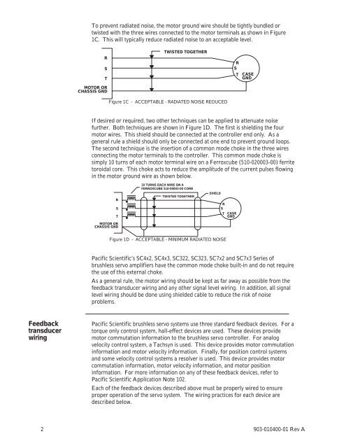
To prevent radiated noise, the motor ground wire should be tightly bundled ortwisted with the three wires connected to the motor terminals as shown in Figure1C. This will typically reduce radiated noise to an acceptable level.RSTMOTOR ORCHASSIS GNDTWISTED TOGETHERRSTCASEGNDFigure 1C - ACCEPTABLE - RADIATED NOISE REDUCEDIf desired or required, two other techniques can be applied to attenuate noisefurther. Both techniques are shown in Figure 1D. The first is shielding the fourmotor wires. This shield should be connected at the controller end only. As ageneral rule a shield should only be connected at one end to prevent ground loops.The second technique is the insertion of a common mode choke in the three wiresconnecting the motor terminals to the controller. This common mode choke issimply 10 turns of each motor terminal wire on a Ferroxcube (510-020003-00) ferritetoroidal core. This choke acts to reduce the amplitude of the current pulses flowingin the motor ground wire as shown below.RSTMOTOR ORCHASSIS GND10 TURNS EACH WIRE ON AFERROXCUBE 510-00003-00 CORETWISTED TOGETHERSHIELDRSTCASEGNDFigure 1D - ACCEPTABLE - MINIMUM RADIATED NOISEPacific Scientific’s SC4x2, SC4x3, SC322, SC323, SC7x2 <strong>and</strong> SC7x3 Series ofbrushless servo amplifiers have the common mode choke built-in <strong>and</strong> do not requirethe use of this external choke.As a general rule, the motor wiring should be kept as far away as possible from thefeedback transducer wiring <strong>and</strong> any other signal level wiring. In addition, all signallevel wiring should be done using shielded cable to reduce the risk of noiseproblems.FeedbacktransducerwiringPacific Scientific brushless servo systems use three st<strong>and</strong>ard feedback devices. For atorque only control system, hall-effect devices are used. These devices providemotor commutation information to the brushless servo controller. For analogvelocity control system, a Tachsyn is used. This device provides motor commutationinformation <strong>and</strong> motor velocity information. Finally, for position control systems<strong>and</strong> some velocity control systems a resolver is used. This device provides motorcommutation information, motor velocity information, <strong>and</strong> motor positioninformation. For more information on any of these feedback devices, refer toPacific Scientific <strong>Application</strong> <strong>Note</strong> 102.Each of the feedback devices described above must be properly wired to ensureproper operation of the servo system. The wiring practices for each device aredescribed below.2 903-010400-01 Rev A