SLIDES
SLIDES
SLIDES

You also want an ePaper? Increase the reach of your titles
YUMPU automatically turns print PDFs into web optimized ePapers that Google loves.
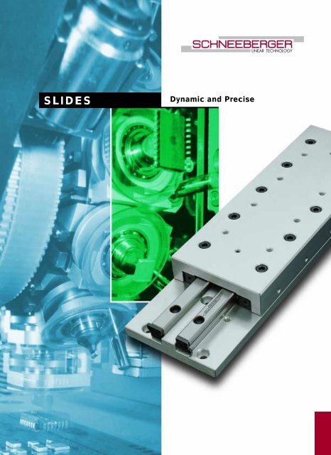
LINEAR TECHNOLOGY<strong>SLIDES</strong>Dynamic and Precise
LINEAR TECHNOLOGYTable of Contents1 Product Overview . . . . . . . . . . . . . . . . . . . . . . . . . . . . . . . . . . . . . . . . . . . . S ● 42 Applications2.1 Die Attach System with ND 1 . . . . . . . . . . . . . . . . . . . . . . . . . . . . . . . . . S ● 62.2 Multimode Fusion Splicer with NK 1 Tables . . . . . . . . . . . . . . . . . . . . . . . S ● 72.3 Printed Circuit Board Assembly with NDN 1 . . . . . . . . . . . . . . . . . . . . . . S ● 82.4 Laser Measuring Device with ND 1 . . . . . . . . . . . . . . . . . . . . . . . . . . . . . S ● 93 Frictionless Tables Type NK3.1 Frictionless Tables Type NK . . . . . . . . . . . . . . . . . . . . . . . . . . . . . . . . . S ● 113.2 Material. . . . . . . . . . . . . . . . . . . . . . . . . . . . . . . . . . . . . . . . . . . . . . . . . S ● 113.3 Standard Model . . . . . . . . . . . . . . . . . . . . . . . . . . . . . . . . . . . . . . . . . . S ● 113.4 Special Models . . . . . . . . . . . . . . . . . . . . . . . . . . . . . . . . . . . . . . . . . . . S ● 113.5 Specifications . . . . . . . . . . . . . . . . . . . . . . . . . . . . . . . . . . . . . . . . . . . . S ● 123.6 Accessories . . . . . . . . . . . . . . . . . . . . . . . . . . . . . . . . . . . . . . . . . . . . . S ● 164 Frictionless Tables Type NKL4.1 Frictionless Tables Type NKL . . . . . . . . . . . . . . . . . . . . . . . . . . . . . . . . S ● 174.2 Material. . . . . . . . . . . . . . . . . . . . . . . . . . . . . . . . . . . . . . . . . . . . . . . . . S ● 174.3 Standard Model . . . . . . . . . . . . . . . . . . . . . . . . . . . . . . . . . . . . . . . . . . S ● 174.4 Special Model . . . . . . . . . . . . . . . . . . . . . . . . . . . . . . . . . . . . . . . . . . . . S ● 174.5 Specifications . . . . . . . . . . . . . . . . . . . . . . . . . . . . . . . . . . . . . . . . . . . . S ● 185 Micro Frictionless Tables Type ND5.1 Micro Frictionless Tables Type ND . . . . . . . . . . . . . . . . . . . . . . . . . . . . S ● 235.2 Material. . . . . . . . . . . . . . . . . . . . . . . . . . . . . . . . . . . . . . . . . . . . . . . . . S ● 235.3 Standard Model . . . . . . . . . . . . . . . . . . . . . . . . . . . . . . . . . . . . . . . . . . S ● 235.4 Special Model . . . . . . . . . . . . . . . . . . . . . . . . . . . . . . . . . . . . . . . . . . . . S ● 235.5 Specifications . . . . . . . . . . . . . . . . . . . . . . . . . . . . . . . . . . . . . . . . . . . . S ● 246 Micro Frictionless Tables Type NDN6.1 Micro Frictionless Tables Type NDN . . . . . . . . . . . . . . . . . . . . . . . . . . . S ● 276.2 Material. . . . . . . . . . . . . . . . . . . . . . . . . . . . . . . . . . . . . . . . . . . . . . . . . S ● 276.3 Standard Model . . . . . . . . . . . . . . . . . . . . . . . . . . . . . . . . . . . . . . . . . . S ● 276.4 Specifications . . . . . . . . . . . . . . . . . . . . . . . . . . . . . . . . . . . . . . . . . . . . S ● 287 Technical Information7.1 Acceptance Tolerances . . . . . . . . . . . . . . . . . . . . . . . . . . . . . . . . . . . . S ● 307.2 Accuracy . . . . . . . . . . . . . . . . . . . . . . . . . . . . . . . . . . . . . . . . . . . . . . . S ● 307.3 Materials . . . . . . . . . . . . . . . . . . . . . . . . . . . . . . . . . . . . . . . . . . . . . . . . S ● 327.4 Permissible Operating Temperatures. . . . . . . . . . . . . . . . . . . . . . . . . . . S ● 327.5 Lubrication . . . . . . . . . . . . . . . . . . . . . . . . . . . . . . . . . . . . . . . . . . . . . . S ● 327.6 Permissible Velocities and Accelerations . . . . . . . . . . . . . . . . . . . . . . . . S ● 327.7 Friction, Running Accuracy and Smoothness . . . . . . . . . . . . . . . . . . . . S ● 328 Design and Fitting Guidelines8.1 Horizontal and Vertical Fitting . . . . . . . . . . . . . . . . . . . . . . . . . . . . . . . . S ● 338.2 Attaching Frictionless Tables. . . . . . . . . . . . . . . . . . . . . . . . . . . . . . . . . S ● 338.3 Preloading Frictionless Tables . . . . . . . . . . . . . . . . . . . . . . . . . . . . . . . . S ● 338.4 Design of Base Unit . . . . . . . . . . . . . . . . . . . . . . . . . . . . . . . . . . . . . . . S ● 338.5 Accessories for Frictionless Tables . . . . . . . . . . . . . . . . . . . . . . . . . . . . S ● 339 Dimensioning Frictionless Tables9.1 Load Carrying Capacity and Operational Life. . . . . . . . . . . . . . . . . . . . . S ● 349.2 Moment Loading. . . . . . . . . . . . . . . . . . . . . . . . . . . . . . . . . . . . . . . . . . S ● 35• 1
1Product OverviewFrictionless Tables Type NK● Single axis model in steel or cast-irondepending on the size● With roller cages● 5 sizes● Lengths from 25 to 510 mm● Strokes from 10 to 450 mm● Supports a variety of applications dueto the many different sizes● For highest accuracy requirements● For highest accelerations availablewith FORMULA-SFrictionless Tables Type NKL● Single axis model● Light design, table components inaluminum● 4 sizes● With roller cages● Lengths from 25 to 410 mm● Strokes from 10 to 280 mm● For highest accelerations availablewith FORMULA-S• 4
LINEAR TECHNOLOGYMicro Frictionless Tables Type ND● Single axis model in steel● 3 sizes● With roller cages● Lengths from 25 to 155 mm● Strokes from 12 to 90 mm● Low friction force● For highest accuracy requirementsProduct OverviewMicro Frictionless Tables Type NDN● Single axis model in corrosion resistantsteel● 3 sizes● With ball cage in brass● Cage centering mechanism whichhelps to avoid cage creep● Length from 10 to 80 mm● Strokes from 5 to 70 mm● For highest accuracy requirements● Suitable for high speed applications• 5
2Applications2.1 Die Attach System with ND 1 One of the ideal applications for the ND 1 table is in Die Attach equipment. Die Attach isone of the central steps in the manufacture of integrated circuits (IC’s). In the first step, awafer full of IC’s is sliced up with a diamond dicing saw. After sawing, the individual IC’sor «die» are picked off of the sawed wafer and placed onto a metal lead frame in the dieattach operation. The lead frame has been prepared with an epoxy adhesive, which securesthe die to the leadframe. In subsequent operations the metal pads on the die areconnected to the metal leads of the frame providing an electrical connection to the printedcircuit board to which the completed IC will eventually be attached. The high speedZ-axis of the die attach machine carries out the actual «pick and place» operation. Theindividual die are picked from a wafer and placed on the lead frame in a specific location.A machine vision system is used to accurately locate the independent positions, of boththe die on the wafer and the leadframe where it will be placed. The accuracy of the joiningof the two components is critical to the success of subsequent operations.Product ND 1Stroke25 mmNominal stroke15 mmOperating orientationverticalPosition accuracy 0.05 mmAcceleration 30 m/s 2Straightness and Flatness of travel 0.004 mm• 6
LINEAR TECHNOLOGY2.2 Multimode Fusion Splicerwith NK 1 TablesMultimode Fusion Splicers are portable optical fibre jointing machines weighing approximately10 kg. These are used in the field for the installation of optical fibre systems, for examplefor LAN’s (Local Area Networks). Using a high precision process, two optical fibresare fusion joined together. Great accuracy is required so that the transmission quality ofthe optical fibre is not significantly reduced. Two clamping devices, one for each fibre,accurately locate and hold the two optical fibres and are guided by SCHNEEBERGERNK 1 roller tables. Prior to splicing, the fibre ends are precisely aligned to each other tosub-micron accuracy in three mutually orthogonal axes. This adjustment is effected usingSCHNEEBERGER NK 1 tables driven by stepper motors. The accuracy of adjustment ismonitored on a built-in LCD screen via an integral CCD camera system and controlledmanually by means of a simple handwheel. Thereupon the fusion process takes place toproduce a high quality, low-loss joint. This whole process takes on average one minute.Finally, the completed splice is protected by a heat shrink sleeve which is applied usingthe fusion splicer’s integral heatoven.ApplicationsProduct NK 1StrokeNominal strokeOperating orientationPosition accuracyAccelerationStraightness and Flatness of travel12 mm10 mmvertical/horizontal0.001 mmlow0.002 mmFibre located in V-grooveSplicer top panelCompression springSCHNEEBERGER SlideSlipper blockCamGearboxStepper motor forY vertical motion(up/down)Axis for Z motion• 7
2.3 Printed Circuit BoardAssembly with NDN 1In this application, NDN 1 micro frictionless tables are utilized for placing electronic componentssuch as resistors, capacitors, coils and integrated circuits on printed circuit boards.With a gripper installed on the top of the SCHNEEBERGER NDN 1 micro frictionless table,the components are picked from a large hopper. The parts are then placed on a specificposition on the printed circuit board with a Z-stroke of the table. In this case, the NDN 1table is driven by a synchronous toothed belt. The SCHNEEBERGER NDN 1 distinguishesitself particularly by its constant precision under the extra demands on service life andaccuracy imposed by the high dynamic loading found in this application.Product NDN 1Stroke20 mmNominal stroke15 mmOperating orientationverticalPosition accuracy0.03 mmAcceleration up to 15 m/s 2Straightness and Flatness of travel 0.003 mm• 8
LINEAR TECHNOLOGY2.4 Laser Measuring Devicewith ND 1In section 2.2 Multimode Fusion Splicer, the connecting of glass fibres in the field wasdescribed. This application involves the measurement of glass fibre connections.The measuring procedure is based on the angle change of a reflector, in which the wavelength of the laser beam is changed and evaluated. The mechanical rotation of the reflectoris controlled through a stepping motor drive with a micrometer spindle. The stepping motoris installed on a roller table ND 1, in order to compensate for the longitudinal movementof the micrometer screw. This makes exceptionally high demands on the running characteristicsof the roller table, since this has a direct influence on the measurement results.Product ND 1StrokeNominal strokeOperating orientationPosition accuracyAccelerationStraightness and Flatness of travel32 mm25 mmhorizontalno special requirementslow0.004 mmRotating Optical ComponentRotation axisLaser UnitMicrometerGlass Fiberoptic FixtureCouplingStepper MotorSCHNEEBERGER MicroFrictionless Table Typ ND 1Stroke 25 mm• 9
3Frictionless Tables Type NKLINEAR TECHNOLOGY3.1 Frictionless Tables Type NKFrictionless Tables Type NK– Single axis model in steel or cast-iron depending on the size– With roller cages– 5 sizes– Lengths from 25 to 510 mm– Strokes from 10 to 450 mm– Supports a variety of applications due to the many different sizes– For highest accuracy requirements– For highest accelerations available with FORMULA-S3.2 Material3.3 Standard Model3.4 Special ModelsSizes NK 1 and 2 = SteelSizes NK 3, 6 and 9 = Cast-ironType NK frictionless tables consist of equal length upper and lower sections and type Rlinear bearings. All tables are equipped with type AC roller cages and type GB endpiecesand can be mounted vertically or horizontally. The lower section includes standardizedattaching holes. The sides opposite to the setscrews in the upper and lower sections canbe used for mounting purposes. For the standard model stroke limiting is made by meansof two screws in the upper section and one screw in the lower section. These screws canwithstand only small forces or impacts in the direction of motion and should not be usedas stops. With FORMULA-S these screws are no more necessary due to the cage assistsystem.Standard Attaching Holes (–B)In the upper section (other hole configurations on request)Roller Cages Type EE (–EE)Plastic material, only available for sizes 6 and 9. Provides sealing against dirt and dust;therefore somewhat stiffer motionBall Cages Type AK (–AK)For reduced sensitivity to dirt. Lower load carrying capacityCage assist integrated (–KS)for high dynamics and all assembly orientations for sizes 3 and 6• 11
3.5 SpecificationsOrder No.Dimensions (mm)A B D w H L L 1 L 2 *L 3 L 4 L 5 *L 6 L 7 b b 1 b 2 b 3 *b 4 d d 1NK 1-25 10 25 1 10 – 3.0NK 1-35 18 35 2 10 1 10 4.5NK 1-45 25 45 3 10 2 10 6NK 1-55 17 30 1.5 32 55 4 10 10 3 10 7.5 7.5 12.5 3.5 18.4 8.6 22 12 10 4.1 2.55NK 1-65 40 65 5 10 4 10 8.5NK 1-75 45 75 6 10 5 10 11NK 1-85 50 85 7 10 6 10 13.5NK 2-35 18 35 1 15 – 3NK 2-50 30 50 2 15 1 15 4.5NK 2-65 40 65 3 15 2 15 7NK 2-80 21 40 2 50 80 4 15 15 3 15 10 9.5 17.5 5 25 11 30 16 15 6 3.5NK 2-95 60 95 5 15 4 15 12NK 2-110 70 110 6 15 5 15 14.5NK 2-125 80 125 7 15 6 15 17NK 3-55 30 55 1 25 – 5.5NK 3-80 45 80 2 25 1 25 10.5NK 3-105 60 105 3 25 2 25 15.5NK 3-130 28 60 3 75 130 4 25 25 3 25 15 20.5 27.5 10 39 17 40 40 25 7.5 4.5NK 3-155 90 155 5 25 4 25 25.5NK 3-180 105 180 6 25 5 25 30.5NK 3-205 130 205 7 25 6 25 30.5* Only with special model B• 12
LINEAR TECHNOLOGYLayout of the standard attaching holes in the lower sectiond 2 *d 3 h h 1 h 2 n s t x y C in N M L in Nm M Q in Nm Weight Fig.in kg250 1.20 1.69 0.08 1350 1.80 2.36 0.112 1450 2.40 3.04 0.144 1M2 M2 5.5 3 – 2.5 4 7 4 8.5 550 3.00 3.71 0.176 2650 3.60 4.39 0.208 2750 4.20 5.06 0.24 2900 5.10 6.08 0.277 2425 2.72 3.83 0.18 1595 4.08 5.36 0.26 1850 6.12 7.65 0.34 1M2 M3 6.5 3 – 3.4 6 8 5 12 1020 7.48 9.18 0.42 21275 9.52 11.48 0.5 21445 10.88 13.01 0.58 21700 12.92 15.30 0.68 2910 7.80 12.74 0.57 11300 11.70 18.20 0.8 11820 16.90 25.48 1.03 1M3 M4 9 4.5 10 5.5 8 10.5 7 18 2210 20.80 30.94 1.26 12730 26.00 38.22 1.49 33120 29.90 43.68 1.72 33510 33.80 49.14 1.95 4Ordering example: 1 Frictionless table NK 3-105 or 1 Frictionless table NK 3-105-B• 13
Order No.Dimensions (mm)A B D w H L L 1 L 2 *L 3 L 4 L 5 *L 6 L 7 b b 1 b 2 b 3 *b 4 d d 1NK 6-110 60 110 1 50 – 16.5NK 6-160 95 160 2 50 1 50 24NK 6-210 130 210 3 50 2 50 31.5NK 6-260 45 100 6 165 260 4 50 50 3 50 30 39 55 10 64 26 60 92 50 11 7NK 6-310 200 310 5 50 4 50 46.5NK 6-360 235 360 6 50 5 50 54NK 6-410 265 410 7 50 6 50 64NK 9-210 130 210 1 100 – 27NK 9-310180 310 2 100 1 100 5260 145 910055NK 9-410 350 410 3 100 2 100 17105 55 98 46 90 135 80 15 9NK 9-510 450 510 4 100 3 100 17* Only with special model B• 14
LINEAR TECHNOLOGYLayout of the standard attaching holes in the lower sectiond 2 *d 3 h h 1 h 2 n n 1 s t x y C in N M L in Nm M Q in Nm Weight Fig.in kg3710 57.24 83.48 3.07 15830 95.40 131.18 4.46 17420 124.02 166.95 5.85 3M4 M6 13 6 15 8 15 15 16 12 31 9540 162.18 214.65 7.24 311660 200.34 262.35 8.63 313250 228.96 298.13 10.02 415370 267.12 345.83 11.41 411700 291.20 421.20 11.8 1M4 M8 16 7 20 11 20 22 21 14.5 4418200 473.20 655.20 17.3 120800 546.00 748.80 22.8 324700 655.20 889.20 28.3 3Ordering example: 1 Frictionless table NK 6-160 or 1 Frictionless table NK 6-160-B• 15
3.6 Accessories Simple Guards (–A)against the ingress of dirt from aboveSize 1 2 3 6 9m 2 3 4 6 11.5• 16
4Frictionless Tables Type NKLLINEAR TECHNOLOGY4.1 Frictionless Tables Type NKLFrictionless Tables Type NKL– Single axis model– Light design, table components in aluminum– 4 sizes– With roller cages– Lengths from 25 to 410 mm– Strokes from 10 to 280 mm– For highest accelerations available with FORMULA-S4.2 Material4.3 Standard Model4.4 Special ModelAluminumType NKL frictionless tables consist of equal length upper and lower sections and type Rlinear bearings. All tables are equipped with type AC roller cages and type GB endpiecesand can be mounted vertically or horizontally. In the upper and lower sections there arestandardized attaching holes. The sides opposite to the setscrews in the upper and lowersections can be used for mounting purposes. For the standard model stroke limiting ismade by means of two screws in the upper section and one screw in the lower section.These screws can withstand only small forces or impacts in the direction of motion andshould not be used as stops.With FORMULA-S these screws are no more necessary due to the cage assist system.Ball Cages Type AK (–AK)For reduced sensitivity to dirt. Lower load carrying capacityRoller Cages Type EE (–EE)Plastic material, only available for size 6. Provides sealing against dirt and dust. Somewhatstiffer motionCage assist integrated (–KS)for high dynamics and all assembly orientations for size 3 and 6• 17
4.5 SpecificationsOrder No.Dimensions (mm)A B D w H L L 1 L 2 L 3 L 4 L 5 L 6 L 7 b b 1 b 2 b 3 dNKL 1-25 10 25 1 10 – 3.0NKL 1-35 18 35 2 10 1 10 4.5NKL 1-45 25 45 3 10 2 10 6NKL 1-55 13 30 1.5 32 55 4 10 10 3 10 7.5 7.5 12.5 3.5 18.4 8.6 22 10 4.1NKL 1-65 40 65 5 10 4 10 8.5NKL 1-75 45 75 6 10 5 10 11NKL 1-85 50 85 7 10 6 10 13.5NKL 2-35 18 35 1 15 – 3NKL 2-50 30 50 2 15 1 15 4.5NKL 2-65 40 65 3 15 2 15 7NKL 2-80 21 40 2 50 80 4 15 15 3 15 10 9.5 17.5 5 25 11 30 15 6NKL 2-95 60 95 5 15 4 15 12NKL 2-110 70 110 6 15 5 15 14.5NKL 2-125 80 125 7 15 6 15 17• 18
LINEAR TECHNOLOGYLayout of the standard attaching holes in the lower sectiond 1 d 2 h h 1 h 2 s t x y C in N M L in Nm M Q in Nm Weight Fig.in kg250 1.20 1.69 0.04 1350 1.80 2.36 0.05 1450 2.40 3.04 0.06 12.55 M2 4.1 1.6 – 4 4.5 4 8.5 550 3.00 3.71 0.075 2650 3.60 4.39 0.09 2750 4.20 5.06 0.105 2900 5.10 6.08 0.12 2425 2.72 3.83 0.11 1595 4.08 5.36 0.15 1850 6.12 7.65 0.19 13.5 M3 6.7 3.2 – 6 8 5 12 1020 7.48 9.18 0.23 21275 9.52 11.48 0.27 21445 10.88 13.01 0.31 21700 12.92 15.30 0.35 2Ordering example: 1 Frictionless table NKL 2-65• 19
Order No.Dimensions (mm)A B D w H L L 1 L 2 L 3 L 4 L 5 L 6 L 7 b b 1 b 2NKL 3-55 30 55 1 25 – 5.5NKL 3-80 45 80 2 25 1 25 10.5NKL 3-105 60 105 3 25 2 25 15.5NKL 3-130 75 130 4 25 3 25 20.5NKL 3-155 90 155 5 25 4 25 25.5NKL 3-180 25 60 3 105 180 6 25 25 5 25 15 30.5 27.5 10 39 17 40NKL 3-205 130 205 7 25 6 25 30.5NKL 3-230 155 230 8 25 7 25 30.5NKL 3-255 180 255 9 25 8 25 30.5NKL 6-110 60 110 1 50 – 16NKL 6-160 95 160 2 50 1 50 23.5NKL 6-210 130 210 3 50 2 50 31NKL 6-260 40 100 6 165 260 4 50 50 3 50 30 38.5 55 10 64 26 60NKL 6-310 200 310 5 50 4 50 46NKL 6-360 265 360 6 50 5 50 38.5NKL 6-410 280 410 7 50 6 50 56• 20
LINEAR TECHNOLOGYLayout of the standard attaching holes in the lower sectionb 3 d d 1 d 2 h h 1 h 2 s t x y C in N M L in Nm M Q in Nm Weight Fig.in kg910 7.80 12.74 0.29 11300 11.70 18.20 0.42 11820 16.90 25.48 0.55 12210 20.80 30.94 0.68 125 7.5 4.5 M4 8.2 3.2 7.5 8 8.5 7 18 2730 26.00 38.22 0.81 33120 29.90 43.68 0.94 33510 33.80 49.14 1.07 43770 36.40 52.78 1.2 44160 40.30 58.24 1.33 53710 57.24 83.48 1.5 15830 95.40 131.18 2.25 17420 124.02 166.95 3 350 11 7 M6 11.5 4.5 12.5 15 13 12 31 9540 162.18 214.65 3.75 311660 200.34 262.35 4.5 312720 219.42 286.20 5.25 314840 257.58 333.90 6 3Ordering example: 1 Frictionless table NKL 6-260• 21
5Micro Frictionless Tables Type NDLINEAR TECHNOLOGY5.1 Micro Frictionless TablesType NDMicro Frictionless Tables Type ND– Single axis model in steel– 3 sizes– With roller cages– Lengths from 25 to 155 mm– Strokes from 12 to 90 mm– Low friction force– For highest accuracy requirements5.2 Material5.3 Standard Model5.4 Special ModelSteelType ND micro frictionless tables consist of equal length upper and lower sections. Thedouble V-shaped lower section is through hardened.All sizes are equipped with type AC roller cages and can be mounted horizontally or vertically.In the upper and lower sections there are standardized attaching holes.Ball Cages Type AK (–AK)For reduced sensitivity to dirt. Lower load carrying capacity• 23
5.5 SpecificationsOrder No.Dimensions (mm)A B B 1 D w H L L 1 L 2 L 3ND 1-25.12 12 25 1 10 1 18ND 1-35.1818 35 2 10 1 288 20 7 1.57.5ND 1-45.25 25 45 3 10 1 20ND 1-55.32 32 55 4 10 1 30ND 2-65.40 40 65 3 15 1 30ND 2-80.50 12 30 12 2 50 80 4 15 10 1 45ND 2-95.60 60 95 5 15 2 30ND 3-105.60 60 105 3 25 1 50ND 3-130.75 16 40 15 3 75 130 4 25 15 1 75ND 3-155.90 90 155 5 25 2 50• 24
LINEAR TECHNOLOGYLayout of the standard attaching holesL 4 b b 1 d d 1 s t x y C in N M L in Nm M Q in Nm Weightin kg3.5 200 0.90 0.80 0.023.5300 1.50 1.20 0.0312.4 14 4.2 M 2.5 4 3.5 1.95 3.912.5 400 2.10 1.60 0.0412.5 550 3.00 2.20 0.05765 5.44 5.16 0.1617.5 20 22 6 M 3 6 5.5 2.3 5.5 1020 7.48 6.89 0.191190 8.84 8.03 0.241690 15.60 13.52 0.4727.5 27 30 7.5 M 4 8 7.5 2.5 8.3 2210 20.80 17.68 0.592730 26.00 21.84 0.70Ordering example: 1 Micro frictionless table ND 2-80.50• 25
6Micro Frictionless Tables Type NDNLINEAR TECHNOLOGY6.1 Micro Frictionless TablesType NDNMicro Frictionless Tables Type NDN– Single axis model in corrosion resistant steel– 3 sizes– With ball cage in brass– Cage centering mechanism which helps to avoid cage creep– Length from 10 to 80 mm– Strokes from 5 to 70 mm– For highest accuracy requirements– Suitable for high speed applications6.2 MaterialCorrision resistant steel6.3 Standard Model The micro frictionless tables NDN consist of upper and lower parts of the same length andcan be utilized horizontally or vertically. They consist of only four components; the lowerand the upper part made of stainless steel, the brass cage and the stainless steel rollingelements. The U-shaped cage joins the two guideways together. As a result, the susceptibilityto cage drift is essentially eliminated. NDN micro frictionless tables, preloaded inassembly to eliminate play, exhibit extremely low push force. NDN products fulfill highspeed requirements with great precision and long service life.• 27
6.4 SpecificationsOrder No.Dimensions (mm)A B B 1 D w H LNDN 05-10.05 5 10NDN 05-15.1010 154 7 4 1NDN 05-20.15 15 20NDN 05-25.20 20 25NDN 1-15.05 5 15NDN 1-20.10 10 20NDN 1-25.15 15 25NDN 1-30.2020 306 10 5 1.5NDN 1-35.25 25 35NDN 1-40.30 30 40NDN 1-45.35 35 45NDN 1-50.40 40 50NDN 2-30.20 20 30NDN 2-40.30 30 40NDN 2-50.4040 508 15 8 2.5NDN 2-60.50 50 60NDN 2-70.60 60 70NDN 2-80.70 70 80* The calculation of the carrying capacity for NDN tables has been performed accordingDIN 636 part 3. A static reliability factor of 3 is taken into consideration.• 28
LINEAR TECHNOLOGYLayout of the standard attaching holes in the lower- and upper sectionNDN 05L 3 L 4 b 1 d 1 s t x *C in N M L in Ncm M Q in Ncm Weightin g1 5 2.5 23 1.5 3 21 8 3.527 2.2 3.6 3– M 1.6 2.1 1.5 1.11 12 4 36 2.8 4.8 41 16 4.5 45 3.5 6 51 8 3.5 50 9 14 51 12 4 60 11 17 71 16 4.5 70 14 20 101 20 580 16 23 124 M 2 3 2.3 1.81 24 5.5 90 19 26 141 28 6 100 21 28 171 32 6.5 110 24 31 191 36 7 120 26 34 211 20 5 140 40 55 281 28 6 170 50 65 361 36 7200 60 75 457 M 2.5 4.5 2.5 2.73 15 7.5 250 80 100 543 18 8 310 100 120 643 20 10 370 120 140 73Ordering example: 1 Frictionless Table NDN 1-30.20• 29
7Technical Information7.1 Acceptance TolerancesAll SCHNEEBERGER frictionless tables aremanufactured as standard with the accuraciesindicated in the tables. Measurement isin the unloaded state on a flat surface.The tolerance figures in the tables are forsingle axis.TypeL25–5055–100105–160NK 165–310315–51025–5055–100NKL 105–160165–310315–41025–50ND 55–100105–15515–30NDN 35–5060–807.2 Accuracy Straightness and FlatnessThe tolerance for Straightness and Flatnessof travel is dependent on the various frictionlesstable models, the size, the lengthetc. This tolerance is shown above in chapter7.1.Closer tolerances can be supplied on request.ParallelismThe tolerances shown in the tables areachieved by measuring the frictionless tablesin the middle position. For this purposethe frictionless tables are placed unloadedon a flat surface.• 30
LINEAR TECHNOLOGYStraightness of Travel in µm Flatness of Travel in µm Parallelism in µm of Table Surfaces;over Stroke Length; Laterally over Stroke Length; at Top in Middle PositionTechnical Information2 2 53 2 103 3 154 3 204 4 254 4 104 4 206 6 306 6 408 8 504 4 155 5 206 6 252 2 53 3 54 4 8Height ToleranceThe height tolerance is 0,1 mm.On request, most types can be supplied inmatched pairs to 0,01 mm.• 31
7.3 MaterialsLinear Bearings and Rolling ElementsWhere no contrary specifications are agreed the following are valid:– Linear bearings material No. 1.2510 or 1.2842– Rolling elements material No. 1.3505– NDN material No. 1.4034Table BodiesManufactured according to details under each frictionless table type.7.4 Permissible OperatingTemperatures7.5 LubricationSCHNEEBERGER frictionless tables can be used at operating temperatures of –40° to+80°C. In cases of doubt, please consult us. Please also note that temperature fluctuationsin operation can have an enormous influence when positioning in the micrometerrange.SCHNEEBERGER frictionless tables are lubricated to protect them against corrosion andwear. The initial factory lubrication can, depending on the operating conditions, suffice foryears.Generally, bearing grease on a lithium saponified base (bearing grease KP2K per DIN51502 respectively DIN 51825) should be used. Drip feed oiling, occasional oiling or lubricatingby means of overspill oil are sufficient. To achieve the lowest rolling friction resistance,mineral base oils are recommended (CLP or HLP; viscosities of ISO VG 15 to 100per DIN 51519). Soluble oil or coolant emulsions should, on the other hand, be kept awayfrom the guides as they dilute or wash away the lubricant. In addition coolant emulsionstend to dry out and become tacky. Lubricants with solid base additives are also unsuitable.Lubrication intervals depend on various factors such as the loading, ambient conditionsetc. Experience has shown that lubricating 2–5 times at equal intervals during the calculatedoperational life suffices.7.6 Permissible Velocitiesand AccelerationsUnder normal conditions SCHNEEBERGER frictionless tables with linear bearings withroller or ball cages can be used at velocities of up to 50 m/min.The permissible acceleration is, in general, 50 m/s 2. These figures can, however, be influencedsubstantially through the selection of the drive, the load and the length etc. In casesof doubt please consult us.With FORMULA-SThe cage remains centered during accelerations up to 150 m/s 2 (15g) and oscillation frequenciesup to 25 Hz.7.7 Friction, Running Accuracyand SmoothnessFor SCHNEEBERGER frictionless tables with roller or ball cages coefficients of frictionrange from 0.0005 to 0.003.In the manufacture of SCHNEEBERGER frictionless tables the requisites for perfect runningsmoothness are created. SCHNEEBERGER plastic and plastic composite cages alsoplay a large part. For successful application special care must be taken with the mountingof the frictionless tables on an adequately machined, low-deformation base.You will find further details in the following section.• 32
8Design and Fitting GuidelinesLINEAR TECHNOLOGY8.1 Horizontal and Vertical Fitting All applications where the direction of motion is horizontal are designated horizontal fitting.All applications where the direction of motion deviates from the horizontal are designatedvertical fitting.All SCHNEEBERGER frictionless tables have preloaded anti-friction guideways and can,therefore, accept moments and forces in any direction (see also 9.2).FORMULA-S allows all mounting orientations with no cage creep anymore.8.2 Attaching Frictionless Tables8.3 Preloading Frictionless TablesSCHNEEBERGER frictionless tables are normally attached to the base structure withstandardized through holes in the base. Various models have, additionally, threaded holeswhich permit alternate mounting.All SCHNEEBERGER frictionless tables have playfree, preloaded antifriction guidewaysand can, therefore, be used without any additional measures accomplished. Preloadingis by means of adjusting screws or ball selection by diameter and needs no readjustment.Design and Fitting Guidelines8.4 Design of Base Unit8.5 Accessories forFrictionless TablesThe advantages of SCHNEEBERGER frictionless tables are best exploited on a rigid, lowdeformation,accurately machined construction. The surface quality of the supportingsurfaces has no direct influence on the operation and run-out behavior of the frictionlesstables. We recommend however, that they should be manufactured with a surface roughnessof between N5 and N7, in order to achieve the desired planeness and parallelismtolerances.According to the type, SCHNEEBERGER frictionless tables type NK can be supplied withaccessories.You can find the relative information under the respective frictionless table types. Shouldthe standard accessories not meet your series production requirements, we are in a positionto supply customized components.• 33
9Dimensioning Frictionless Tables9.1 Load Carrying Capacity andOperational LifeIn applying frictionless tables, the primary consideration is the relationship of the appliedload to the load carrying capacity. The elastic deformation (rigidity) must also be evaluated.The load carrying capacities of the individual frictionless tables are based on the fundamentalsestablished by ISO and DIN for the calculation of roller bearings (ISO 281, for NDNDIN 636, part 3). The load carrying capacity C is the load with which a nominal operationallife of 100 000 m travel is achieved, given that the size and direction of the load remainunchanged and the line of application is vertical onto the frictionless table surface.By definition, the latest research results have shown that the static load should not begreater than the dynamic load. The reason for this lies in the fatigue behavior which isalways initiated at the highest loaded point. In the case of an absolutely constant loadduring standstill and in operation, the fatigue process will start at that point where the staticload is present longest. The C-values given are used in the operational life equation tocalculate the operational life resulting with a given load.The operational life is the travel in metres which is made by a frictionless table before thefirst signs of metal fatigue appear on any of the anti-friction guideway components. TheB 10 operational life is achieved when 90% of a statistical sample of frictionless tables meetor exceed the prescribed amount of travel.Dynamic loading capacity CAs previously mentioned, the load carrying capacity C is based on an operational life of100 000 m. Some manufacturers use, for various reasons, a larger load carrying capacitywith 50 000 metres operational life. The C 50 values for SCHNEEBERGER frictionless tablesare calculated as follows:C 50 = C • 1.23 for frictionless tables with rollersC 50 = C • 1.26 for frictionless tables with ballsLife ExpectancyAccording to the DIN and ISO standards, the load carrying capacities for roller bearingsare given in such a manner that from the operational life equation a value results which,with 90% probability, will be exceeded. Should this probability not suffice, then theoperational life must be shortened with the a 1 factor per the following tables:LifeExpectancy % 90 95 96 97 98 99a 1 1 0.62 0.53 0.44 0.33 0.21• 34
LINEAR TECHNOLOGYOperational life calculationThe operational life L, the dynamic load carrying capacity C (N) and the loading P (N) havethe following relationship:9.2 Moment LoadingL = a 1 ( C Pwhereby a is the probable life expectancy factor. The operational life in hours can be calculatedwhen the single stroke H (m) and the time needed for it t (s) are known:L • tL h in hH • 3600) 10/3 • 10 5 m for rollers and needlesL = a 1 ( C P ) 3 • 10 5 m for ballsIn addition to the load carrying capacity C,you will find in the tables of dimensions forthe individual frictionless tables the permissiblevalues for moment loading. M L is themaximum possible torque lengthwise andM Q the maximum possible torque crosswise.StraightnessTravelDimensioning Frictionless Tablesof Travel Yaw/M LRoll/M QPitch/ M LFlatnessof Travel• 35