Application Note- Wiring Grounding and Shielding Techniques.pdf
Application Note- Wiring Grounding and Shielding Techniques.pdf
Application Note- Wiring Grounding and Shielding Techniques.pdf

Create successful ePaper yourself
Turn your PDF publications into a flip-book with our unique Google optimized e-Paper software.
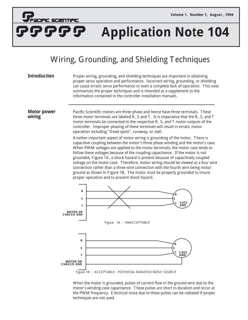
Volume 1, Number 1, August , 1994<strong>Application</strong> <strong>Note</strong> 104<strong>Wiring</strong>, <strong>Grounding</strong>, <strong>and</strong> <strong>Shielding</strong> <strong>Techniques</strong>IntroductionProper wiring, grounding, <strong>and</strong> shielding techniques are important in obtainingproper servo operation <strong>and</strong> performance. Incorrect wiring, grounding, or shieldingcan cause erratic servo performance or even a complete lack of operation. This notesummarizes the proper techniques <strong>and</strong> is intended as a supplement to theinformation contained in the controller installation manuals.Motor powerwiringPacific Scientific motors are three phase <strong>and</strong> hence have three terminals. Thesethree motor terminals are labeled R, S <strong>and</strong> T. It is imperative that the R, S, <strong>and</strong> Tmotor terminals be connected to the respective R, S, <strong>and</strong> T motor outputs of thecontroller. Improper phasing of these terminals will result in erratic motoroperation including “Dead spots”, runaway, or stall.Another important aspect of motor wiring is grounding of the motor. There iscapacitive coupling between the motor’s three phase winding <strong>and</strong> the motor’s case.When PWM voltages are applied to the motor terminals, the motor case tends tofollow these voltages because of the coupling capacitance. If the motor is notgrounded, Figure 1A, a shock hazard is present because of capacitively coupledvoltage on the motor case. Therefore, motor wiring should be viewed as a four wireconnection rather than a three wire connection with the fourth wire being motorground as shown in Figure 1B. The motor must be properly grounded to insureproper operation <strong>and</strong> to prevent shock hazard.RSTMOTOR ORCHASSIS GNDRSTCASEGNDFigure 1A - UNACCEPTABLERSTMOTOR ORCHASSIS GNDRSTCASEGNDFigure 1B - ACCEPTABLE - POTENTIAL RADIATED NOISE SOURCEWhen the motor is grounded, pulses of current flow in the ground wire due to themotor’s winding-case capacitance. These pulses are short in duration <strong>and</strong> occur atthe PWM frequency. Electrical noise due to these pulses can be radiated if propertechniques are not used.
To prevent radiated noise, the motor ground wire should be tightly bundled ortwisted with the three wires connected to the motor terminals as shown in Figure1C. This will typically reduce radiated noise to an acceptable level.RSTMOTOR ORCHASSIS GNDTWISTED TOGETHERRSTCASEGNDFigure 1C - ACCEPTABLE - RADIATED NOISE REDUCEDIf desired or required, two other techniques can be applied to attenuate noisefurther. Both techniques are shown in Figure 1D. The first is shielding the fourmotor wires. This shield should be connected at the controller end only. As ageneral rule a shield should only be connected at one end to prevent ground loops.The second technique is the insertion of a common mode choke in the three wiresconnecting the motor terminals to the controller. This common mode choke issimply 10 turns of each motor terminal wire on a Ferroxcube (510-020003-00) ferritetoroidal core. This choke acts to reduce the amplitude of the current pulses flowingin the motor ground wire as shown below.RSTMOTOR ORCHASSIS GND10 TURNS EACH WIRE ON AFERROXCUBE 510-00003-00 CORETWISTED TOGETHERSHIELDRSTCASEGNDFigure 1D - ACCEPTABLE - MINIMUM RADIATED NOISEPacific Scientific’s SC4x2, SC4x3, SC322, SC323, SC7x2 <strong>and</strong> SC7x3 Series ofbrushless servo amplifiers have the common mode choke built-in <strong>and</strong> do not requirethe use of this external choke.As a general rule, the motor wiring should be kept as far away as possible from thefeedback transducer wiring <strong>and</strong> any other signal level wiring. In addition, all signallevel wiring should be done using shielded cable to reduce the risk of noiseproblems.FeedbacktransducerwiringPacific Scientific brushless servo systems use three st<strong>and</strong>ard feedback devices. For atorque only control system, hall-effect devices are used. These devices providemotor commutation information to the brushless servo controller. For analogvelocity control system, a Tachsyn is used. This device provides motor commutationinformation <strong>and</strong> motor velocity information. Finally, for position control systems<strong>and</strong> some velocity control systems a resolver is used. This device provides motorcommutation information, motor velocity information, <strong>and</strong> motor positioninformation. For more information on any of these feedback devices, refer toPacific Scientific <strong>Application</strong> <strong>Note</strong> 102.Each of the feedback devices described above must be properly wired to ensureproper operation of the servo system. The wiring practices for each device aredescribed below.2 903-010400-01 Rev A
Hall effectdevicesThree Hall-effect devices are required to provide commutation information forPacific Scientific three-phase brushless servo motors. The Hall-effect outputs areopen collector transistor. These outputs drive the brushless servo controller sensorinputs which have resistor pull-ups.<strong>Wiring</strong> for the Hall-effect devices consists of one wire for each of the three sensorsignals <strong>and</strong> two wires which provide power to the Hall-effect devices. The threesensor signal wires should be twisted together as shown in Figure 2A.SENSOR 1SENSOR 2SENSOR 3+12 V+12 V RTN123+ VDCGNDFigure 2A - ACCEPTABLEFor improved noise immunity, the five wires can be placed in a shield which isconnected to the 12V RTN at the controller as shown in Figure 2B. This isespecially important if the motor wiring is run near (within 12 inches) of the sensorwiring. The shield should only be connected at the controller end.SENSOR 1SENSOR 2SENSOR 3+12 V+12 V RTN123+ VDCGNDFigure 2B - ACCEPTABLE - IMPROVED NOISE IMMUNITYTachsynwiringThe Tachsyn is a five wire device that operates similar to a resolver. two of theTachsyn wires are a high frequency excitation signal. The remaining three wires areoutput which supply commutation <strong>and</strong> velocity information to the controller. Bothsets of wires must be shielded <strong>and</strong> the two excitation wires must be in a separateshield from the output wires. If they are not placed in separate shields, the motorwill not operate or will operate erratically.TACHSYN PHASE 1TACHSYN PHASE 2TACHSYN PHASE 3TACHSYN EXCITATIONEXCITATION RETURNSHIELD OR RTN123EXCITFigure 3A - UNACCEPTABLEThe Tachsyn must always be wired as shown in Figure 3B. Any other wiring schemewill result in improper motor operation.903-010400-01 Rev A 3
TACHSYN PHASE 1TACHSYN PHASE 2TACHSYN PHASE 3SHIELDTACHSYN EXCITATIONEXCITATION RETURNSHIELD123EXCIT.Figure 3B - ACCEPTABLEResolverwiringThe resolver is a six wire device. As with the Tachsyn, two of the wires are a highfrequency excitation signal. The remaining four wires are outputs which supplycommutation, velocity, <strong>and</strong> position information to the controller. These four wiresare separated into two distinct pairs: sine (S1 <strong>and</strong> S3) <strong>and</strong> cosine (S2 <strong>and</strong> S4).Hence the six wires are segregated into three pairs. Each pair must be run in aseparate shield to insure proper motor operation.S1S3S2S4R1R2S1S3S2S4R1R2SHIELDFigure 4A - UNACCEPTABLEThe resolver must always be wired as shown in Figure 4B. Any other wiring schememay result in improper motor operation.S1S3S2S4S1S3S2S4R1R2R1R2<strong>Grounding</strong><strong>Shielding</strong>SHIELDFigure 4B - ACCEPTABLEThe grounding procedures listed in the controller installation manuals should befollowed. In general, the following rules should be observed.All component chassis ground points <strong>and</strong> signal ground or common points should betied together at a single point (star connection). This point should then be tied witha single conductor to an earth ground point. This form of grounding preventsground loops <strong>and</strong> insures that all components are properly grounded against shockhazard.In general, it is good practice to shield all wires carrying low level signals. This isespecially important if the signal level wires are run near power level wiring such asmotor wires or relay wires.When shielding wires, connect only one end of the shield, preferably the source end.Connecting both ends of a shield will result in ground loops. It is recommended thatthe unconnected end of the shield be insulated to prevent accidental connection.4 903-010400-01 Rev A