System Introspection for System Analysis on Mobile Devices
System Introspection for System Analysis on Mobile Devices
System Introspection for System Analysis on Mobile Devices

You also want an ePaper? Increase the reach of your titles
YUMPU automatically turns print PDFs into web optimized ePapers that Google loves.
Bringing <str<strong>on</strong>g>System</str<strong>on</strong>g> <str<strong>on</strong>g>Introspecti<strong>on</strong></str<strong>on</strong>g> to <strong>Mobile</strong> <strong>Devices</strong><str<strong>on</strong>g>for</str<strong>on</strong>g> <str<strong>on</strong>g>System</str<strong>on</strong>g> <str<strong>on</strong>g>Analysis</str<strong>on</strong>g>Master ThesisFaculty of TechnologyBielefeld Universityby :Andreas Kippakipp@techfak.uni-bielefeld.desupervisors :Dr.-Ing. habil. Sven WachsmuthDipl.-In<str<strong>on</strong>g>for</str<strong>on</strong>g>m. Frederic SiepmannDipl.-In<str<strong>on</strong>g>for</str<strong>on</strong>g>m. Ingo LütkebohleMarch 30, 2011
7.2.2 Preparati<strong>on</strong>s . . . . . . . . . . . . . . . . . . . . . . . . 557.2.3 Method . . . . . . . . . . . . . . . . . . . . . . . . . . . 567.2.4 Results . . . . . . . . . . . . . . . . . . . . . . . . . . . 577.3 Observing the CPU Load of the Robot <str<strong>on</strong>g>System</str<strong>on</strong>g> . . . . . . . . . 597.3.1 Goal . . . . . . . . . . . . . . . . . . . . . . . . . . . . . 597.3.2 Preparati<strong>on</strong>s . . . . . . . . . . . . . . . . . . . . . . . . 607.3.3 Method . . . . . . . . . . . . . . . . . . . . . . . . . . . 607.3.4 Results . . . . . . . . . . . . . . . . . . . . . . . . . . . 618 C<strong>on</strong>clusi<strong>on</strong>s 649 Outlook 66Bibliography 69List of Figures 71List of Tables and Listings 73Appendix 74ii
Abstract<str<strong>on</strong>g>System</str<strong>on</strong>g> <str<strong>on</strong>g>Introspecti<strong>on</strong></str<strong>on</strong>g> is essential to understand the inner processes c<strong>on</strong>trollinga robot which is acting in an aut<strong>on</strong>omous way. To get an idea of the innerstates of the c<strong>on</strong>trolling comp<strong>on</strong>ents a developer does not want to interruptthe running system. Moreover analyzing a dozen of complex log files <strong>on</strong>cethe robot has ended per<str<strong>on</strong>g>for</str<strong>on</strong>g>ming a task c<strong>on</strong>sumes a lot of time. This thesispresents a design and an implementati<strong>on</strong> of a system <str<strong>on</strong>g>for</str<strong>on</strong>g> observati<strong>on</strong> that canbe attached to a robot system. The system will collect data of the robotand <str<strong>on</strong>g>for</str<strong>on</strong>g>ward it to a client <str<strong>on</strong>g>for</str<strong>on</strong>g> presentati<strong>on</strong>. XMPP is used as communicati<strong>on</strong>framework which provides functi<strong>on</strong>ality <str<strong>on</strong>g>for</str<strong>on</strong>g> exchanging data over a network.The described system was successfully evaluated by attaching the system tothe ToBI plat<str<strong>on</strong>g>for</str<strong>on</strong>g>m.iii
1 Introducti<strong>on</strong>Observing complex systems like robots can be difficult whenever the integratedcomp<strong>on</strong>ents are not speaking <strong>on</strong>e language. In the c<strong>on</strong>text of this thesis asystem is developed that helps to combine different in<str<strong>on</strong>g>for</str<strong>on</strong>g>mati<strong>on</strong> queues andgives an inside view of a robot system.1.1 Motivati<strong>on</strong>: Developing Complex Robot <str<strong>on</strong>g>System</str<strong>on</strong>g>sToBI is a robot plat<str<strong>on</strong>g>for</str<strong>on</strong>g>m descended from the BIRON plat<str<strong>on</strong>g>for</str<strong>on</strong>g>m (see chapter4) created and developed at the University of Bielefeld. ToBI can behaveaut<strong>on</strong>omously in an unknown envir<strong>on</strong>ment and per<str<strong>on</strong>g>for</str<strong>on</strong>g>m different tasks. Someexamples of these tasks are following and interacting with pers<strong>on</strong>s, exploringunknown envir<strong>on</strong>ments or recognizing objects and manipulate them with agripper. Every single task needs several comp<strong>on</strong>ents running <strong>on</strong> the robot.To achieve an aut<strong>on</strong>omous behavior, the different comp<strong>on</strong>ents, running <strong>on</strong>different hardware systems must be combined.ToBI per<str<strong>on</strong>g>for</str<strong>on</strong>g>ms different tasks at the Robocup@Home 1 c<strong>on</strong>test. A c<strong>on</strong>creteexample <str<strong>on</strong>g>for</str<strong>on</strong>g> a task is to follow a pers<strong>on</strong> guiding the robot around an unknownroom. For this task the robot uses different sensors and actuators (e.g. cameras,laser range finder). With algorithms to extract pers<strong>on</strong>s from the dataof each comp<strong>on</strong>ent, the robot is capable of following the pers<strong>on</strong> by using itsnavigati<strong>on</strong> comp<strong>on</strong>ents to drive towards the pers<strong>on</strong>. All the comp<strong>on</strong>ents publishin<str<strong>on</strong>g>for</str<strong>on</strong>g>mati<strong>on</strong> that needs to be aligned in time. For example, the positi<strong>on</strong> offaces must be compared to the positi<strong>on</strong>s of legs. By combining the data, therobot can analyze the data and make a decisi<strong>on</strong> <strong>on</strong> further acti<strong>on</strong>s, like movingtowards the pers<strong>on</strong>.When a developer has to compose the interacti<strong>on</strong> between different comp<strong>on</strong>ents,a general understanding of each comp<strong>on</strong>ent is needed. A comp<strong>on</strong>ent isc<strong>on</strong>trolled by a piece of software which is often not created by the developeritself. To understand how a comp<strong>on</strong>ent works, the developer can try to readand analyze the output of each comp<strong>on</strong>ent. There is no standardizati<strong>on</strong> <strong>on</strong>1 http://www.webcitati<strong>on</strong>.org/5wrZXRnjK - Robocup@Home1
output, so each comp<strong>on</strong>ent is offering its own kind of in<str<strong>on</strong>g>for</str<strong>on</strong>g>mati<strong>on</strong> with its <strong>on</strong>frequency. This frequency can be quite high, and the human percepti<strong>on</strong> is oftennot capable of reading and comprehending as fast as a comp<strong>on</strong>ent (Dys<strong>on</strong> andHaselgrove, 2001). Also the plotted data is often not in a human readable <str<strong>on</strong>g>for</str<strong>on</strong>g>m.To make the data readable it must be filtered or trans<str<strong>on</strong>g>for</str<strong>on</strong>g>med somehow. Whenobserving the robot the developer often needs more then <strong>on</strong>e comp<strong>on</strong>ent. Sotwo or more windows displaying the comp<strong>on</strong>ents output have to be m<strong>on</strong>itoredat <strong>on</strong>ce. The ToBI plat<str<strong>on</strong>g>for</str<strong>on</strong>g>m runs more then 20 comp<strong>on</strong>ents in parallel, whichmakes observing without collecting and filtering the data to fewer views nearlyimpossible.Besides, the idea behind robots like ToBI is to make the robot behave in anaut<strong>on</strong>omous way. Many robot systems are designed as closed systems and oftenthere is no way to observe the inner processes from the outside. If the robotstops acting as expected, the developer has to move to the robot and check itscomp<strong>on</strong>ents. For example a worst case scenario can be an experiment with ahuman-robot-interacti<strong>on</strong> where the robot suddenly stops interacting. Checkingthe comp<strong>on</strong>ents of the robot can corrupt all recorded data due to the fact thatthe robot may recognize not <strong>on</strong>ly the subject but also the developer.My motivati<strong>on</strong> is to make observati<strong>on</strong> of the inner processes possible by creatinga system that can be attached to the robot. This system should offerviews <strong>on</strong> the robots comp<strong>on</strong>ents and let the developer choose what he wants toobserve. These in<str<strong>on</strong>g>for</str<strong>on</strong>g>mati<strong>on</strong> should be filtered to the important elements andthen be presented <strong>on</strong> an external device. Due to the limited resources of therobot the system must be designed lightweight and while active it should notinfluence the normal behavior of the robot.1.2 Bringing the <str<strong>on</strong>g>System</str<strong>on</strong>g> to <strong>Mobile</strong> <strong>Devices</strong>Many c<strong>on</strong>trol and observati<strong>on</strong> systems (see chapter 2) use pers<strong>on</strong>al computersto present published data. Sometimes there are situati<strong>on</strong>s where the developeris separated from the robot and a pers<strong>on</strong>al computer or laptop is not available(e.g. while <strong>on</strong> business trip). Nowadays mobile devices are capable of using theinternet <str<strong>on</strong>g>for</str<strong>on</strong>g> communicati<strong>on</strong>, so the idea is to bring the in<str<strong>on</strong>g>for</str<strong>on</strong>g>mati<strong>on</strong> to such adevice. With improving per<str<strong>on</strong>g>for</str<strong>on</strong>g>mance many devices are capable to process a lotof in<str<strong>on</strong>g>for</str<strong>on</strong>g>mati<strong>on</strong> at <strong>on</strong>ce and can be used <str<strong>on</strong>g>for</str<strong>on</strong>g> the robot observati<strong>on</strong> menti<strong>on</strong>ed.My idea was to integrate the output of a system collecting the data of comp<strong>on</strong>entsof a robot <strong>on</strong> such a mobile device. Filtering the data <strong>on</strong> the systemcollecting allows to minimize the data to be exchanged. With the reduced data2
even complex in<str<strong>on</strong>g>for</str<strong>on</strong>g>mati<strong>on</strong> can be transferred to and displayed <strong>on</strong> a mobile device.The communicati<strong>on</strong> also can be handled over the internet, which allowsthe system to send the data to devices all over the world. The developer canbe miles away to check the robots state and give advice <str<strong>on</strong>g>for</str<strong>on</strong>g> users at the localside. Like the resources <strong>on</strong> a robot the resources of mobile devices are surelylimited. The system needs to be lightweight and save resources as much aspossible. For example, when observing the robot the mobile ph<strong>on</strong>e should notuse up all the battery within 5 minutes.1.3 Use Cases: What a Developer does with the<str<strong>on</strong>g>System</str<strong>on</strong>g>In the appendix of this thesis the use cases <str<strong>on</strong>g>for</str<strong>on</strong>g> the interacti<strong>on</strong> between a developerand the system attached to the robot are described. Important usecases are the request <str<strong>on</strong>g>for</str<strong>on</strong>g> in<str<strong>on</strong>g>for</str<strong>on</strong>g>mati<strong>on</strong> of the comp<strong>on</strong>ents <strong>on</strong> the robot and therequest <str<strong>on</strong>g>for</str<strong>on</strong>g> comp<strong>on</strong>ents to be logged.The use case “Request a comp<strong>on</strong>ent” explains the way how a comp<strong>on</strong>ent isrequested from the robot. When the expert is successfully c<strong>on</strong>nected to theobservati<strong>on</strong> system, he can request the list of comp<strong>on</strong>ents offered by the system.Selecting a single comp<strong>on</strong>ent will trigger the comp<strong>on</strong>ent <strong>on</strong> the probe to startpublishing its in<str<strong>on</strong>g>for</str<strong>on</strong>g>mati<strong>on</strong>. The in<str<strong>on</strong>g>for</str<strong>on</strong>g>mati<strong>on</strong> is displayed as different views <strong>on</strong>the mobile device.The use case “Request comp<strong>on</strong>ents to be logged” starts a logging cycle <strong>on</strong> theprobe. This cycle collects data from selected comp<strong>on</strong>ents, filters it to the needsof the developer and prints them to a logging file. The developer can selectfrom available comp<strong>on</strong>ents <strong>on</strong> a selecti<strong>on</strong> view and execute the cycle. Whilethe system probe is collecting, it creates temporary files <str<strong>on</strong>g>for</str<strong>on</strong>g> backup. When thedeveloper stops the cycle or disc<strong>on</strong>nects from the probe, the collected data willbe saved as a unique file <strong>on</strong> the file system.1.4 OutlineComp<strong>on</strong>ents running <strong>on</strong> a robot can be hard to observe. In this thesis a systemis designed and implemented, that allows to filter in<str<strong>on</strong>g>for</str<strong>on</strong>g>mati<strong>on</strong> from comp<strong>on</strong>entsof the robot and collect them into several views <strong>on</strong> external devices like mobileph<strong>on</strong>es. Chapter 2 introduces some work that is related to the the systemcreated in this thesis. Chapter 3 describes the requirements <str<strong>on</strong>g>for</str<strong>on</strong>g> the systemand chapter 4 explains the systems envir<strong>on</strong>ment. Chapter 5 covers the design3
of the system and the decisi<strong>on</strong>s made <str<strong>on</strong>g>for</str<strong>on</strong>g> the communicati<strong>on</strong> interface. Theimplementati<strong>on</strong> is described in chapter 6. This chapter shows the implementati<strong>on</strong>of the system attached to the software of the robot and two differentclients created <str<strong>on</strong>g>for</str<strong>on</strong>g> the representati<strong>on</strong> of the in<str<strong>on</strong>g>for</str<strong>on</strong>g>mati<strong>on</strong>. The capability of theimplementati<strong>on</strong> is tested and described in chapter 7. Goal of the evaluati<strong>on</strong>was to show the occurring system load <strong>on</strong> the robot running a task and thelatency <str<strong>on</strong>g>for</str<strong>on</strong>g> exchanging data <strong>on</strong> the mobile device. Chapter 8 gives a c<strong>on</strong>clusi<strong>on</strong><strong>on</strong> how the implementati<strong>on</strong> worked out followed by chapter 9 giving an outlook<strong>on</strong> future work to be d<strong>on</strong>e with the system.4
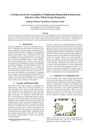
2 Related WorkThis chapter gives an overview of relevant topics related to the idea behindthe system created in the c<strong>on</strong>text of this thesis. Naturally related topics arethe remote c<strong>on</strong>trol of a system and the c<strong>on</strong>trol of robot systems with telerobotics.Work d<strong>on</strong>e in these fields is described and some difference to thesystem designed are menti<strong>on</strong>ed.2.1 Remote C<strong>on</strong>trol and TeleroboticsSheridan (1992) gives an introducti<strong>on</strong> to the paradigm of telerobotics. Themain idea is to c<strong>on</strong>trol a system by using a remote system. On the remote sidea supervisor c<strong>on</strong>trols a system which is c<strong>on</strong>nected to the system <strong>on</strong> the localside with a barrier inbetween. Examples <str<strong>on</strong>g>for</str<strong>on</strong>g> this barrier can be a local networkor even the internet. The remote system provides commands the supervisorcan use to manipulate the local side. Selected commands are send to the localsystem over the barrier. The local system takes these commands and translatesthem into commands <str<strong>on</strong>g>for</str<strong>on</strong>g> the executi<strong>on</strong> of different processes (Figure 2.1).Figure 2.1: Basic c<strong>on</strong>cept of telerobot supervisory c<strong>on</strong>trol - On theleft side the supervisor selects commands to be send andchecks in<str<strong>on</strong>g>for</str<strong>on</strong>g>mati<strong>on</strong> received from the local side. Thecommands are sent over the barrier to the local systemshown <strong>on</strong> the right. The local system translates the commands<str<strong>on</strong>g>for</str<strong>on</strong>g> executi<strong>on</strong> <strong>on</strong> the robot. In<str<strong>on</strong>g>for</str<strong>on</strong>g>mati<strong>on</strong> from therobot are send back to the supervisor again over the barrier.[From Ferrell and Sheridan (1967)]Today a lot of remote c<strong>on</strong>trol systems can be found in the industry, in scientificwork or used <str<strong>on</strong>g>for</str<strong>on</strong>g> educati<strong>on</strong>al purpose at schools. Marin et al. (2005)5
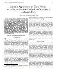
created a telelaboratory where two robot arms are remotely programmed withan multimedia user interface(Figure 2.2). The main idea of the laboratory wasto evaluate the capabilities of the user interface <str<strong>on</strong>g>for</str<strong>on</strong>g> remote c<strong>on</strong>trol. At a locallaboratory the setup c<strong>on</strong>tains two robot arms m<strong>on</strong>itored by several cameras.A server allows c<strong>on</strong>nected users <strong>on</strong> the remote side to send commands <str<strong>on</strong>g>for</str<strong>on</strong>g> manipulati<strong>on</strong><strong>on</strong> the local side. To observe the manipulati<strong>on</strong> the remote interfaceoffers different views of the cameras and the data collected at the local side.The communicati<strong>on</strong> between the local and the remote side was established oversockets using TCP/IP. The remote side used a given Java library handling allthe communicati<strong>on</strong> overhead. Also the library c<strong>on</strong>sists of a skelet<strong>on</strong> <str<strong>on</strong>g>for</str<strong>on</strong>g> creatingexperiments with predefined commands. To evaluate the system testexperiments were designed and the latency between sending commands andthe executi<strong>on</strong> in the laboratory was measured. The results showed that sendingdata over the internet can be difficult due to the availability of bandwidthat a given moment. The analyzed data showed that there is no guarantee thata command send from the remote side arrives at the local side in a minimumperiod of time.(a) Robot arms at the local side(b) Graphical remote interfaceFigure 2.2: Observati<strong>on</strong> software <str<strong>on</strong>g>for</str<strong>on</strong>g> a telelaboratory - Image b showsthe interface which allows to create experiments that manipulatethe two arms shown in image a. The systemoffers different views of the local side by using severalcameras. Experiments are designed <strong>on</strong> the remote sideand exchanged via the internet [From Marin et al. (2005)]There are some points of the telelaboratory that are similar to the system6
designed in this thesis. Like the setup of the laboratory the designed system canbe used to observe a system by collecting data <strong>on</strong> the robot side and <str<strong>on</strong>g>for</str<strong>on</strong>g>wardit to a remote side. One difference to the laboratory is the high couplingbetween remote and local side. The remote system <str<strong>on</strong>g>for</str<strong>on</strong>g> the laboratory wasused to c<strong>on</strong>trol the system. The system designed in this thesis will primarilybe used to observe the system to get an idea of what is processed inside therobot at the current moment. Also the attached system should not directlyinfluence the robot due to the fact that the robot should still behave in anaut<strong>on</strong>omously way.More similar is the setup designed by Lin et al. (2007). Their system c<strong>on</strong>trolsa SONY Aibo 1 robot over the internet pers<strong>on</strong>al digital assistant(PDA). Therewhere five different servers <strong>on</strong> the robot side used to c<strong>on</strong>trol and publish dataof the different comp<strong>on</strong>ents. On the client side according modules were offeredthat were directly c<strong>on</strong>nected to their counterpart <strong>on</strong> the robot. All Comp<strong>on</strong>entsare displayed <strong>on</strong> a graphical user interface <strong>on</strong> the PDA. With the mobile devicethe user was able to c<strong>on</strong>trol the movement of the robot and to set the angle ofthe head c<strong>on</strong>taining the camera.Figure 2.3: S<strong>on</strong>y AIBO c<strong>on</strong>trolled with a HP iPAQ rx195 2 over the internet- The c<strong>on</strong>trol software <strong>on</strong> the device allows to navigatethe robot and m<strong>on</strong>itor the <strong>on</strong>board camera [FromLin et al. (2007)]The capability of the system was tested by navigating the robot through apredefined course. While navigating the round-trip time of the data exchangedbetween robot and PDA was measured. The experiment was carried out atdifferent day times and showed that the round-trip time was not c<strong>on</strong>stantdue to sharing the network bandwidth with other systems (Figure 2.4). Thissystem offers several services to c<strong>on</strong>trol the robot and observe several sensors.1 http://www.webcitati<strong>on</strong>.org/5wiCWyImO - SONY Aibo7
Like the telelaboratory there is a high coupling between the remote side andthe robot at the local side. The in<str<strong>on</strong>g>for</str<strong>on</strong>g>mati<strong>on</strong> send to the PDA were presentedinside <strong>on</strong>e screen. On a mobile device the resources and the space to displaydata are limited. For the approach made in this thesis the system presents eachcomp<strong>on</strong>ent <strong>on</strong> a different view and lets the developer choose which comp<strong>on</strong>enthe wants to observe. This also helps to minimize latency <strong>on</strong> exchanging data.By <strong>on</strong>ly sending data of requested comp<strong>on</strong>ents the payload of each messagecan be minimized.(a) Course <str<strong>on</strong>g>for</str<strong>on</strong>g> the PDA evaluati<strong>on</strong>(b) Results of the PDA evaluati<strong>on</strong>Figure 2.4: Measuring the capability of the remote c<strong>on</strong>trol - Imagea shows the course the user has to navigate through.Image b shows the measured average round-trip timesand the traveling times at different day times.[From Linet al. (2007)]A great difference between the systems menti<strong>on</strong>ed and the system created inthis thesis is the part of observati<strong>on</strong>. Other then a pure remote the systemdesigned is attached to a running system and collects data of the comp<strong>on</strong>entsof the robot. With this data the internal processes of the robot can be presentedwhich can help to understand what the robot is currently planning andper<str<strong>on</strong>g>for</str<strong>on</strong>g>ming.8
3 RequirementsIn the c<strong>on</strong>text of this thesis the development of a system is described that canbe attached to the software of a robot <str<strong>on</strong>g>for</str<strong>on</strong>g> observati<strong>on</strong> of running comp<strong>on</strong>ents,without influence <strong>on</strong> the normal behavior. This chapter describes the requirementsgiven <str<strong>on</strong>g>for</str<strong>on</strong>g> such a system. There are several elements to be distinguishedin this thesis:robotprobeclientdeveloperthe system to observe and to collect in<str<strong>on</strong>g>for</str<strong>on</strong>g>mati<strong>on</strong>fromthe applicati<strong>on</strong> attached to the robot software<str<strong>on</strong>g>for</str<strong>on</strong>g> observati<strong>on</strong>the applicati<strong>on</strong> running <strong>on</strong> an external devicecommunicating with the probethe expert using the applicati<strong>on</strong> to observe therobotWho is the Expert?In the c<strong>on</strong>text of this thesis an expert is the pers<strong>on</strong> developing the comp<strong>on</strong>entsof the robot. He extends existing comp<strong>on</strong>ents and adds new comp<strong>on</strong>ents to therobot. The expert combines all available comp<strong>on</strong>ents to make the robot behavein an aut<strong>on</strong>omous way. He is not the end user interacting with the robot.The <strong>on</strong>ly interacti<strong>on</strong> an expert does is <str<strong>on</strong>g>for</str<strong>on</strong>g> testing purpose of the comp<strong>on</strong>entsdeveloped.<str<strong>on</strong>g>System</str<strong>on</strong>g> Requirements of the DeveloperTo get an idea of the inner processes of the robot some requirements are givenby the developer.Requirement 1:Only present in<str<strong>on</strong>g>for</str<strong>on</strong>g>mati<strong>on</strong> requested and filter them to the importantparts with a human readable frequencyWhen observing a comp<strong>on</strong>ent <strong>on</strong> the robot, the in<str<strong>on</strong>g>for</str<strong>on</strong>g>mati<strong>on</strong> available can bequiet complex and offers more detail then needed. The data is often presented9
with a very high frequency which makes it hard <str<strong>on</strong>g>for</str<strong>on</strong>g> a human to observe acomp<strong>on</strong>ent of the robot.Requirement 2:Send and receive in<str<strong>on</strong>g>for</str<strong>on</strong>g>mati<strong>on</strong> with minimized delayThe delay between the data send and the time of receiving it <strong>on</strong> the clientmust be minimized. A high delay can make the data obsolete which makes adecisi<strong>on</strong> <strong>on</strong> the robots state dispensable.Requirement 3:Change comp<strong>on</strong>ent views at any timeOften the expert wants to check other comp<strong>on</strong>ents <strong>on</strong> the run, to make surechanges <strong>on</strong> <strong>on</strong>e comp<strong>on</strong>ent do not influence other comp<strong>on</strong>ents.Requirement 4:Cooperative work without influencing other observersOften more then <strong>on</strong>e expert is working with the system. Every expert needs hisown view <strong>on</strong>to the comp<strong>on</strong>ents without interfering other experts. A multi-userenvir<strong>on</strong>ment is there<str<strong>on</strong>g>for</str<strong>on</strong>g>e beneficial.Requirement 5:C<strong>on</strong>trol logging of filtered in<str<strong>on</strong>g>for</str<strong>on</strong>g>mati<strong>on</strong> <strong>on</strong> command and create uniquelogging filesMany comp<strong>on</strong>ents already create logging files that can be analyzed when therobot has ended its current per<str<strong>on</strong>g>for</str<strong>on</strong>g>mance. These files are written <strong>on</strong>ce percomp<strong>on</strong>ent and must be aligned by the developer himself. Also the comp<strong>on</strong>entslog their data when the robot starts until it has stopped working. For a posthocanalysis the probe must collect and filter in<str<strong>on</strong>g>for</str<strong>on</strong>g>mati<strong>on</strong> from comp<strong>on</strong>entsselected by the developer. The developer must be able to initiate the processand stop it <strong>on</strong> command. All collected data must be saved into a single file <str<strong>on</strong>g>for</str<strong>on</strong>g>each developer.Requirement 6:Extensi<strong>on</strong> must be possibleDue to the changes of the comp<strong>on</strong>ents of the robot, extensi<strong>on</strong> of the systemmust be possible. New comp<strong>on</strong>ents must be easily attached to the system.Requirement 7:Establish a wireless c<strong>on</strong>necti<strong>on</strong> to the probeDue to the need that the robot acts in an aut<strong>on</strong>omous way, the expert does notwant to move towards the robot <str<strong>on</strong>g>for</str<strong>on</strong>g> observati<strong>on</strong> of comp<strong>on</strong>ents. The c<strong>on</strong>necti<strong>on</strong>10
to the probe needs to be wireless. For example this supports remote observati<strong>on</strong>while the robot is participating in an experiment. If possible the system mustbe available over the internet. This allows the expert to m<strong>on</strong>itor changes evenif he is not at the local side of the robot.<str<strong>on</strong>g>System</str<strong>on</strong>g> Requirements of the RobotThough the system is attached to the software of a robot, some requirementsare given by the robot itself.Requirement 8:Minimum influence <strong>on</strong> the robot and inactive when not usedOn the robot a lot of comp<strong>on</strong>ents are executed in parallel. Many of thesecomp<strong>on</strong>ents c<strong>on</strong>sume resources which are limited by the robots system. Theprobe attached should <strong>on</strong>ly use a minimum of the resources available. Whilethe probe is active the normal behavior of the robot should not be influencedby any means necessary. To achieve an minimum influence, the probe should<strong>on</strong>ly be active whenever a developer is c<strong>on</strong>nected to the probe and deactivatedif not used.Requirement 9:No hard coded c<strong>on</strong>necti<strong>on</strong> between robots comp<strong>on</strong>ents and the systemprobeDue to improving technologies the comp<strong>on</strong>ents <strong>on</strong> the robot can change. Theprobe must capsule the c<strong>on</strong>necti<strong>on</strong> reading and c<strong>on</strong>trolling comp<strong>on</strong>ents of therobot to make changes <strong>on</strong> <strong>on</strong> both sides possible without affecting the wholesystem.<str<strong>on</strong>g>System</str<strong>on</strong>g> Requirements of the ProbeThe probe publishes in<str<strong>on</strong>g>for</str<strong>on</strong>g>mati<strong>on</strong> to observe the robot. It is attached to thesoftware of the robot and uses the resources available.Requirement 10:Observati<strong>on</strong> of comp<strong>on</strong>ents must allow parallelism and multi-userobservati<strong>on</strong>Each comp<strong>on</strong>ent inside the probe should be running <strong>on</strong> its own thread. Thisoffers parallelism and allows multiple users to observe different in<str<strong>on</strong>g>for</str<strong>on</strong>g>mati<strong>on</strong>queues.Requirement 11:Well defined communicati<strong>on</strong> interface <str<strong>on</strong>g>for</str<strong>on</strong>g> implementing different communicati<strong>on</strong>frameworks11
Due to improving technology the used communicati<strong>on</strong> may be replaced later<strong>on</strong>. To make the communicati<strong>on</strong> exchangeable an interface must be createdthat allows to change the underlying communicati<strong>on</strong> framework.<str<strong>on</strong>g>System</str<strong>on</strong>g> Requirements of the ClientThe client displays the in<str<strong>on</strong>g>for</str<strong>on</strong>g>mati<strong>on</strong> published by the probe within differentviews.Requirement 12:Applicati<strong>on</strong> running with minimized resource usage to save systemresourcesThe resources <strong>on</strong> a mobile device are limited. The applicati<strong>on</strong> has to belightweight and should not block the device due to excessive resource usage.For example the battery drain should be reduced by decreasing the neededCPU usage.Requirement 13:Well defined communicati<strong>on</strong> interface with same structure then theprobeThe applicati<strong>on</strong> <strong>on</strong> the client must use the same communicati<strong>on</strong> interface thesystem probe uses. This ensures that both systems use the same base <str<strong>on</strong>g>for</str<strong>on</strong>g> communicati<strong>on</strong>.Like the system probe this interface must be interchangeable.Requirement 14:Create different views that can be changed <strong>on</strong> request and providea good usability <str<strong>on</strong>g>for</str<strong>on</strong>g> the developerSwitching the views must be possible at any time. The usability of these viewsmust satisfy the experts requirements.Requirement 15:Support <str<strong>on</strong>g>for</str<strong>on</strong>g> extensi<strong>on</strong> according to changes <strong>on</strong> the probeDue to changes <strong>on</strong> the probe the views <strong>on</strong> the applicati<strong>on</strong> must be extensible.12
4 <str<strong>on</strong>g>System</str<strong>on</strong>g> Envir<strong>on</strong>ment and ToolsThis chapter describes the envir<strong>on</strong>ment <str<strong>on</strong>g>for</str<strong>on</strong>g> the system implemented in. Itwill give an introducti<strong>on</strong> of the robot plat<str<strong>on</strong>g>for</str<strong>on</strong>g>m used and the interface used bythe plat<str<strong>on</strong>g>for</str<strong>on</strong>g>m <str<strong>on</strong>g>for</str<strong>on</strong>g> c<strong>on</strong>necting hardware comp<strong>on</strong>ents. Also the operating systemof the used mobile device and the communicati<strong>on</strong> framework is covered. Thedescripti<strong>on</strong> of the envir<strong>on</strong>ment is given at a higher level and provides no details<strong>on</strong> lower functi<strong>on</strong>alities.4.1 Robot Plat<str<strong>on</strong>g>for</str<strong>on</strong>g>ms: BIRON and ToBIIn the c<strong>on</strong>text of this thesis the probe and the client where both developed towork with the ToBI plat<str<strong>on</strong>g>for</str<strong>on</strong>g>m (Figure 4.1). ToBI is a project of the CITEC 1Central Lab Facilities at the University of Bielefeld 2 descended from the BielefeldRobot Compani<strong>on</strong> plat<str<strong>on</strong>g>for</str<strong>on</strong>g>m (BIRON). ToBI is the plat<str<strong>on</strong>g>for</str<strong>on</strong>g>m of the Team ofBielefeld used to participate in the Robocup@Home competiti<strong>on</strong>(Wachsmuthet al., 2011). The plat<str<strong>on</strong>g>for</str<strong>on</strong>g>m uses several comp<strong>on</strong>ents c<strong>on</strong>trolled by two laptops inthe backpack of the robot. With this comp<strong>on</strong>ents and the software developedat the Central Lab ToBI can behave in an aut<strong>on</strong>omous way in an unknownenvir<strong>on</strong>ment. For the communicati<strong>on</strong> between the software and the hardwareToBI uses the B<strong>on</strong>SAI interface (see chapter 4.2). Examples <str<strong>on</strong>g>for</str<strong>on</strong>g> the sensorsand actuators integrated <strong>on</strong> the plat<str<strong>on</strong>g>for</str<strong>on</strong>g>m are the 180 degree laser range finder(SICK 3 ), several cameras <str<strong>on</strong>g>for</str<strong>on</strong>g> visual percepti<strong>on</strong>, a Katana-Arm 4 <str<strong>on</strong>g>for</str<strong>on</strong>g> graspingor a stereo microph<strong>on</strong>e <str<strong>on</strong>g>for</str<strong>on</strong>g> voice recogniti<strong>on</strong> placed <strong>on</strong> top of the robot. Atthe Robocup@Home c<strong>on</strong>test ToBI per<str<strong>on</strong>g>for</str<strong>on</strong>g>ms tasks like following pers<strong>on</strong>s, navigatingin an unknown envir<strong>on</strong>ment or grasping objects with its gripper. Theoperati<strong>on</strong> system <strong>on</strong> both notebooks is Ubuntu Linux and the software behindthe different comp<strong>on</strong>ents is written with the programming languages C++ 5and Java 6 .1 http://www.cit-ec.de/ToBI - ToBI Team of Bielefeld2 http://www.uni-bielefeld.de/ - University of Bielefeld3 http://www.webcitati<strong>on</strong>.org/5wiFVLrFA - SICK Laser Range Finder4 http://www.webcitati<strong>on</strong>.org/5wiFjsR2R - Katana Arm5 http://www.webcitati<strong>on</strong>.org/5xY0pIOYj - C++ Reference6 http://www.webcitati<strong>on</strong>.org/5wuOWGp5I - Java Technology Network by Oracle13
Figure 4.1: ToBI plat<str<strong>on</strong>g>for</str<strong>on</strong>g>m used at the Robocup@Home competiti<strong>on</strong>- On the right side the comp<strong>on</strong>ents used: microph<strong>on</strong>e,camera, Swissranger-camera, Katana-Arm andSICK laser range finder [From Wachsmuth et al. (2011)]4.2 Bielefeld Sensor Actuator Abstracti<strong>on</strong> Layer(B<strong>on</strong>SAI)The B<strong>on</strong>SAI interface provides an abstract view to the sensors and actuators<strong>on</strong> robot plat<str<strong>on</strong>g>for</str<strong>on</strong>g>ms. A Java API allows developers to c<strong>on</strong>trol actuators orquery sensors from a higher level. The API itself c<strong>on</strong>trols the communicati<strong>on</strong>between higher and lower levels (see Figure 4.2). B<strong>on</strong>SAI also providescross-modal sensors that combine several comp<strong>on</strong>ents into <strong>on</strong>e sensor class.One example <str<strong>on</strong>g>for</str<strong>on</strong>g> a cross-modal sensor is the Pers<strong>on</strong>Tracker, which combineslaser data with camera images. An example <str<strong>on</strong>g>for</str<strong>on</strong>g> a cross-modal actuator is theNavigati<strong>on</strong>Actuator combining comp<strong>on</strong>ents to c<strong>on</strong>trol the navigati<strong>on</strong> of therobot(e.g. driving, obstacle avoidance, path planning).4.3 Operating <str<strong>on</strong>g>System</str<strong>on</strong>g> <strong>on</strong> the <strong>Mobile</strong> DeviceFor mobile devices the operating system of choice used in this thesis is theandroid operati<strong>on</strong> system 7 . Android is a software plat<str<strong>on</strong>g>for</str<strong>on</strong>g>m developed by the7 http://www.webcitati<strong>on</strong>.org/5wiFsqc0j- The Android Operati<strong>on</strong> <str<strong>on</strong>g>System</str<strong>on</strong>g>14
Figure 4.2: The different layer of B<strong>on</strong>SAI - The top layer c<strong>on</strong>tainselements <str<strong>on</strong>g>for</str<strong>on</strong>g> complex behaviors, the middle layerholds functi<strong>on</strong>al comp<strong>on</strong>ents <str<strong>on</strong>g>for</str<strong>on</strong>g> base tasks and the bottomlayer c<strong>on</strong>trols low level hardware comp<strong>on</strong>ents [FromWachsmuth et al. (2011)]Open Handset Alliance 8 . The architecture behind Android provides an operatingsystem, middle-ware and several key applicati<strong>on</strong>s placed in differentlayers (Figure 4.3). Android applicati<strong>on</strong>s can be written with the Java programminglanguage through the Android SDK 9 . Android comes with support<str<strong>on</strong>g>for</str<strong>on</strong>g> wireless c<strong>on</strong>necti<strong>on</strong>s (Bluetooth, WIFI, EDGE, 3G), hardware comp<strong>on</strong>ents(cameras, GPS, accelerometer) and media support. Android relies <strong>on</strong> a Linuxkernel which acts as abstracti<strong>on</strong> layer between hardware and software.Android offers an open development plat<str<strong>on</strong>g>for</str<strong>on</strong>g>m to allow developers the creati<strong>on</strong>of rich and innovative applicati<strong>on</strong>s. Each Android applicati<strong>on</strong>s runs withinits own life cycle (Figure 4.4) and is called activity. An activity c<strong>on</strong>sists ofa class c<strong>on</strong>taining the logic and an XML file describing the layout of the activity.The life cycle describes the different states of an activity presented bydifferent methods. The <strong>on</strong>Create()-method is called <strong>on</strong>ce an activity startsand initializes the comp<strong>on</strong>ents. The <strong>on</strong>Start()-method is triggered when allc<strong>on</strong>figurati<strong>on</strong> of the creati<strong>on</strong> state has ended. Once started the activity runsin the <str<strong>on</strong>g>for</str<strong>on</strong>g>eground of the device within the <strong>on</strong>Resume()-method. In this methodthe interacti<strong>on</strong> with the user takes place. If the user stops the activity it is notdirectly destroyed. The state of the activity is changed to <strong>on</strong>Pause() and then<strong>on</strong>Stop(). In this state the operati<strong>on</strong> system places the activity in the background.If the activity is requested again the <strong>on</strong>Restart()-method is called. Ifthe activity has been terminated by the operati<strong>on</strong> system due to the need ofresources the <strong>on</strong>Create()-method is called if the activity is requested. If theactivities interacti<strong>on</strong> is finally finished the <strong>on</strong>Destroy()-method is called andthe activity ends. One applicati<strong>on</strong> can c<strong>on</strong>tain several activities to provide interacti<strong>on</strong>with the user. The operating system there<str<strong>on</strong>g>for</str<strong>on</strong>g>e decides which activityis running in <str<strong>on</strong>g>for</str<strong>on</strong>g>eground and sends unused activities to the background.8 http://www.webcitati<strong>on</strong>.org/5wiFwDWLg - Open Handset Alliance9 http://www.webcitati<strong>on</strong>.org/5wrOKYh2w - Android Developer Guide15
Figure 4.3: The architecture behind android - The top layer c<strong>on</strong>tainsstandard applicati<strong>on</strong>s. The applicati<strong>on</strong> frameworkoffers interface <str<strong>on</strong>g>for</str<strong>on</strong>g> high level comp<strong>on</strong>ents. The librariesc<strong>on</strong>tains functi<strong>on</strong>ality used by the applicati<strong>on</strong> framework.The Linux kernel c<strong>on</strong>trols the low comp<strong>on</strong>ents and thehardware [From the Android Developer Guide]4.4 XMPP, Openfire and the SMACK LibraryFor the communicati<strong>on</strong> between the probe and the client a communicati<strong>on</strong>framework is needed. In this thesis the communicati<strong>on</strong> framework of choiceis the Extended Messaging and Presence Protocol (XMPP 10 ). XMPP is anopen-standard communicati<strong>on</strong> protocol based <strong>on</strong> the Extensible Markup Language(XML11 ) published by the XMPP Standards Foundati<strong>on</strong> (XSF 12 ). Saint-Andre (2005) gives an introducti<strong>on</strong> <strong>on</strong> streaming XML with XMPP.XMPP uses streams to exchange XML elements between two entities over anetwork. The first-level child element send over such a stream is called stanza(Saint-Andre, 2004). There are three core stanzas <str<strong>on</strong>g>for</str<strong>on</strong>g> communicati<strong>on</strong>:used to push in<str<strong>on</strong>g>for</str<strong>on</strong>g>mati<strong>on</strong> from <strong>on</strong>e entity to anothersend in<str<strong>on</strong>g>for</str<strong>on</strong>g>mati<strong>on</strong> about network availability of <strong>on</strong>e entity<str<strong>on</strong>g>for</str<strong>on</strong>g> info or query in<str<strong>on</strong>g>for</str<strong>on</strong>g>mati<strong>on</strong> between entities10 http://www.webcitati<strong>on</strong>.org/5wiG3zxxE - Extended Messaging and Presence Protocol11 http://www.webcitati<strong>on</strong>.org/5xNK6MKGA - Extensible Markup Language12 http://www.webcitati<strong>on</strong>.org/5wiGCGjXV - XMPP Standards Foundati<strong>on</strong>16
Figure 4.4: Life-cycle of an android activity - Each activity is initializedby calling the <strong>on</strong>Create() method. Inactive activitiesare placed in the background of the operati<strong>on</strong> system[From the Android Developer Guide]A client c<strong>on</strong>nects and opens a stream to a server and the server opens a streamback to that client. Once c<strong>on</strong>nected the server sends the rooster to the client.The rooster c<strong>on</strong>tains all other clients known to the client. When the rooster isloaded, the <strong>on</strong>line presence is delivered to all clients of the rooster. Each clientreturns its own presence. Whenever a message is send to another client, themessage is send to the server which then <str<strong>on</strong>g>for</str<strong>on</strong>g>wards the message to the recipient.If the recipient is not in the domain of the server, the server negotiates a serverto-serverc<strong>on</strong>necti<strong>on</strong> to the recipients server which delivers the message to itsclient. Figure 4.5 shows a typical message sessi<strong>on</strong> c<strong>on</strong>taining elements fromc<strong>on</strong>necting to a server and exchanging messages.This work uses the message stanza <str<strong>on</strong>g>for</str<strong>on</strong>g> data exchange between the probe andthe client (see chapter 6.1). The data exchanged is primarily using simpledata structures. Most of the data can be packed into an XML structure and17
Figure 4.5: Typical instant messaging sessi<strong>on</strong> - 1) Establish c<strong>on</strong>necti<strong>on</strong>to the server “M<strong>on</strong>tague.lit“. 2) Request roosterc<strong>on</strong>taining known friend accounts. 3) Make own presenceavailable to c<strong>on</strong>tacts of the rooster. 4) Receivepresence of c<strong>on</strong>tacts from rooster. 5) Exchange messagewith another c<strong>on</strong>tact [From Saint-Andre (2005)]attached to a message stanza. Listing 4.1 shows a typical message stanza.A message c<strong>on</strong>tains the name of the sender, the recipient the message is <str<strong>on</strong>g>for</str<strong>on</strong>g>wardedto and the body c<strong>on</strong>taining the text to be send. XMPP also allows toextend these message with XML elements.XMPP Library <str<strong>on</strong>g>for</str<strong>on</strong>g> JavaThe probe and the client are both implemented in Java (see chapter 6). Touse XMPP within Java the SMACK 13 library is integrated. SMACK offers anopen source API with functi<strong>on</strong>ality <str<strong>on</strong>g>for</str<strong>on</strong>g> c<strong>on</strong>necting to a server and exchangingmessages between different clients. There is also a port of the library <str<strong>on</strong>g>for</str<strong>on</strong>g> theandroid operati<strong>on</strong> system. SMACK allows to extend the message stanza withvalue pairs added as properties.13 http://www.webcitati<strong>on</strong>.org/5wiKn3W0C - SMACK library by ignite realtime18
1 2 Hello user 2!3 Listing 4.1: Typical stanza <str<strong>on</strong>g>for</str<strong>on</strong>g> a message - The message stanza holdsthe attributes <str<strong>on</strong>g>for</str<strong>on</strong>g> the sender and the recipient. The textto be send is placed inside a body element.XMPP ServerPublic XMPP servers can be found <strong>on</strong> the internet. For testing purpose theprobe and a local XMPP server have been installed <strong>on</strong> the same laptop. AsXMPP server used <str<strong>on</strong>g>for</str<strong>on</strong>g> the communicati<strong>on</strong> between the probe and the clientthe Openfire 14 server is used. Openfire is an open source server written in Javawith supports <str<strong>on</strong>g>for</str<strong>on</strong>g> XMPP communicati<strong>on</strong>.14 http://www.webcitati<strong>on</strong>.org/5wiKd8MIK - XMPP Server by ignite realtime19
5 <str<strong>on</strong>g>System</str<strong>on</strong>g> DesignThe following chapter covers the design of the probe, the client and the communicati<strong>on</strong>interface used <str<strong>on</strong>g>for</str<strong>on</strong>g> communicati<strong>on</strong> between both entities. The designof each element is described in detail here. To distinguish the comp<strong>on</strong>ents ofthe robot and the probe, comp<strong>on</strong>ents running <strong>on</strong> the probe will be referred toas comp<strong>on</strong>ent threads. Comp<strong>on</strong>ents of the robot will be referred to simply ascomp<strong>on</strong>ents.Requirements revisitedA robot acting in an aut<strong>on</strong>omous way with a lot of comp<strong>on</strong>ents running inparallel is limited in resources it can spare. Especially ToBI running over 20comp<strong>on</strong>ents c<strong>on</strong>trolled by two laptops is limited. One of the main requirements<str<strong>on</strong>g>for</str<strong>on</strong>g> the probe and the client is the minimized use of resources available. Tominimize the influence <strong>on</strong> the behavior of the robot this requirement mustbe c<strong>on</strong>sidered permanently. Another important requirement is to create anexchangeable communicati<strong>on</strong> interface. Due to changes of the comp<strong>on</strong>ents,the payload of data is not fix and can change very fast. For example thefrequency of in<str<strong>on</strong>g>for</str<strong>on</strong>g>mati<strong>on</strong> retrieval may be higher then the used communicati<strong>on</strong>technology can handle. A promising way to deal with this problem is to capsulethe communicati<strong>on</strong> interface beginning at the design. Due to the fact thatoften groups of developers integrate comp<strong>on</strong>ents the system needs to supportmultiple users observing at the same time which requires parallel work to betaken into c<strong>on</strong>siderati<strong>on</strong>. Also extensi<strong>on</strong> of the system must be possible. Whennew comp<strong>on</strong>ents are attached to the robot these comp<strong>on</strong>ents must be easilyadded to the probe and the client.Overview of all <str<strong>on</strong>g>System</str<strong>on</strong>g> ElementsFigure 5.1 shows the architecture of the whole system c<strong>on</strong>taining the robot,the probe and the client. To capsule the robots comp<strong>on</strong>ents the probe uses theB<strong>on</strong>SAI interface (see chapter 4.2). The probe and the client use their own20
implementati<strong>on</strong> of the designed communicati<strong>on</strong> interface. Messages betweenthe probe and the client are exchanged via a communicati<strong>on</strong> server.Figure 5.1: Overview of the designed architecture - On the left sideis the robot providing its comp<strong>on</strong>ents by using the B<strong>on</strong>-SAI interface. Probe and client are c<strong>on</strong>nected via thecommunicati<strong>on</strong> server.5.1 Communicati<strong>on</strong> InterfaceTo handle the communicati<strong>on</strong> between the probe and the client a communicati<strong>on</strong>interface is designed to be implemented <strong>on</strong> the different entities. The ideabehind the interface is to capsule all needed communicati<strong>on</strong> overhead to thisinterface. Also by implementing the interface <strong>on</strong> both systems the same understandingof message exchange is guaranteed. The communicati<strong>on</strong> interfacec<strong>on</strong>trols the in<str<strong>on</strong>g>for</str<strong>on</strong>g>mati<strong>on</strong> flow between c<strong>on</strong>nected entities and the communicati<strong>on</strong>server. The main functi<strong>on</strong>alities that are needed are establishing ac<strong>on</strong>necti<strong>on</strong> to the communicati<strong>on</strong> server and the exchange of messages am<strong>on</strong>gc<strong>on</strong>nected entities. A handshake mechanism by sending a message and waiting<str<strong>on</strong>g>for</str<strong>on</strong>g> a resp<strong>on</strong>se is used to acknowledge the c<strong>on</strong>necti<strong>on</strong> between two entities. Tom<strong>on</strong>itor the c<strong>on</strong>necti<strong>on</strong> between the entities a beac<strong>on</strong> is used. This beac<strong>on</strong>must be exchanged to assure that both sides are available.Entities in this thesis are the probe and the client. At startup both entitiesmust c<strong>on</strong>nect to a c<strong>on</strong>necti<strong>on</strong> server by using a c<strong>on</strong>necti<strong>on</strong> c<strong>on</strong>figurati<strong>on</strong>. Thec<strong>on</strong>figurati<strong>on</strong> is distinguished from the source by using a c<strong>on</strong>figurati<strong>on</strong> file.When the client is c<strong>on</strong>nected it sends a message to the probe requesting toestablish a communicati<strong>on</strong> channel. The probe acknowledges the request andadds the client to a list of known clients. This list is held by the probe <str<strong>on</strong>g>for</str<strong>on</strong>g>a whole runtime. Once the c<strong>on</strong>necti<strong>on</strong> between probe and client is created,the client can request data of comp<strong>on</strong>ent threads c<strong>on</strong>trolled by the probe. Requestsare <str<strong>on</strong>g>for</str<strong>on</strong>g>warded to the comp<strong>on</strong>ents which send data to the client. Figure5.2 shows how a message is created and transferred from the probe over acommunicati<strong>on</strong> server to the client.21
Figure 5.2: Message exchange between probe and client - On theleft side is the comp<strong>on</strong>ent thread publishing new data <str<strong>on</strong>g>for</str<strong>on</strong>g>c<strong>on</strong>nected clients. The data is send to the communicati<strong>on</strong>interface that handles all the communicati<strong>on</strong> withthe communicati<strong>on</strong> server. The server itself <str<strong>on</strong>g>for</str<strong>on</strong>g>wards themessage to the client. The communicati<strong>on</strong> interface <strong>on</strong>the client side notifies all observers. Each observer thenchecks the message and processes it if needed.Using Publish / SubscribeThe mechanism behind exchanging the data is using the publish/subscribeparadigm (Eugster et al., 2003). One entity subscribes to a publisher. Thepublisher collects data and <str<strong>on</strong>g>for</str<strong>on</strong>g>wards it to all subscribers. The probe offersservices and publishes their data <strong>on</strong> request. The client can subscribe to sucha service. In c<strong>on</strong>trast to a standard implementati<strong>on</strong> of the publish/subscribeparadigm the publisher also knows the subscriber and vise versa. A comp<strong>on</strong>entthread is not <strong>on</strong>ly acting as a publisher. Each comp<strong>on</strong>ent thread can alsoreceive commands which can change how the data is published. These commandsmay also change the state of a comp<strong>on</strong>ent thread. An example couldbe a comp<strong>on</strong>ent that has several parameters <str<strong>on</strong>g>for</str<strong>on</strong>g> changing the process of filteringthe data presented. The client knows the publisher and can directly sendcommands. Also this can be used to minimize the need of c<strong>on</strong>trol overheadand decrease the delay between sending and receiving a command. Specificcommands are <str<strong>on</strong>g>for</str<strong>on</strong>g>warded to a comp<strong>on</strong>ent thread which can directly use thecommands <str<strong>on</strong>g>for</str<strong>on</strong>g> further processing.To notify entities of incoming messages, the communicati<strong>on</strong> interface is usingthe observer pattern (Freeman et al. (2004), pages 37-78). For the exchange ofdata between the probe and the client, each message created c<strong>on</strong>tains the TAGof the sending element and the TAG of the comp<strong>on</strong>ent that receives the data.A TAG is unique to the system and allows to identify its elements. Whenevera new message is received, the interface notifies its observers. Each elementobserving this interface checks if the message c<strong>on</strong>tains its TAG and then reads22
and processes the data. Each observer is inactive as l<strong>on</strong>g as no messages are<str<strong>on</strong>g>for</str<strong>on</strong>g>warded. This allows the system to save resources normally used <str<strong>on</strong>g>for</str<strong>on</strong>g> activelym<strong>on</strong>itoring the communicati<strong>on</strong> (e.g. polling). Comp<strong>on</strong>ent threads do not needto permanently check if new messages have arrived. Figure 5.3 shows thecommunicati<strong>on</strong> flow by using the observer pattern.Figure 5.3: Communicati<strong>on</strong> flow with observer pattern - The communicati<strong>on</strong>interface listens to new messages from thecommunicati<strong>on</strong> server. New messages are <str<strong>on</strong>g>for</str<strong>on</strong>g>warded tothe interface. Once received, the interface notifies all observers.Each observer checks the message and processesthe data if needed.M<strong>on</strong>itoring the C<strong>on</strong>necti<strong>on</strong>To assure that the c<strong>on</strong>necti<strong>on</strong> between probe and client is permanently alive,a m<strong>on</strong>itoring system is needed. To m<strong>on</strong>itor the c<strong>on</strong>necti<strong>on</strong> a beac<strong>on</strong> system isused. Henry et al. (1998) used a beac<strong>on</strong> to m<strong>on</strong>itor the state of a spacecraft.The spacecraft sends t<strong>on</strong>es with defined frequencies. From this frequency thestate of the spacecraft can be derived. For this thesis a similar approach is used.The idea of a beac<strong>on</strong> was to save system resources if the c<strong>on</strong>necti<strong>on</strong> betweenthe probe and the client got lost. A beac<strong>on</strong> allows the probe to m<strong>on</strong>itor thec<strong>on</strong>necti<strong>on</strong> to each client with minimal effect <strong>on</strong> the c<strong>on</strong>necti<strong>on</strong> itself. Whenthe client c<strong>on</strong>nects to the probe, the probe will send a beac<strong>on</strong> to the client in agiven frequency. The client has to answer the beac<strong>on</strong> by sending a new beac<strong>on</strong>to the probe. This technique offers several advantages. It allows the probeto manage its comp<strong>on</strong>ent threads. If a client is disc<strong>on</strong>nected due to missingbeac<strong>on</strong>s all comp<strong>on</strong>ent threads sending data to the client can be notified aboutthe disc<strong>on</strong>nect. Besides the beac<strong>on</strong> that is transferred additi<strong>on</strong>ally c<strong>on</strong>tains atimestamp, which allows to check the round-trip time between probe and client.It can also be used to synchr<strong>on</strong>ize the time <strong>on</strong> both systems. For example theprobe can act as time giver and provide its time to all c<strong>on</strong>nected clients. Figure5.4 shows the sequence of a single beac<strong>on</strong> exchange.23
Figure 5.4: Beac<strong>on</strong> running between probe and client - The probesends a beac<strong>on</strong> with a given frequency and waits <str<strong>on</strong>g>for</str<strong>on</strong>g> ananswer. When the client receives the beac<strong>on</strong> it sends ananswer in return.5.2 Probe - The Server SideThe probe is attached to the software of a robot and acts like a server publishingdata of the comp<strong>on</strong>ents of the robot. This data can be live observed byrequesting a comp<strong>on</strong>ent thread publishing its in<str<strong>on</strong>g>for</str<strong>on</strong>g>mati<strong>on</strong> or logged to the filesystem <str<strong>on</strong>g>for</str<strong>on</strong>g> post-hoc-analysis. Two main features can be defined as followed:Live Observati<strong>on</strong>Logging Cyclecollects data of a comp<strong>on</strong>ent of the robot and<str<strong>on</strong>g>for</str<strong>on</strong>g>wards the data packed into messages to c<strong>on</strong>nectedclientscollects data of selected comp<strong>on</strong>ents and savesthem with a timestamp <strong>on</strong> the file system of theprobeFor both features several elements are needed to c<strong>on</strong>trol the processes betweenprobe and c<strong>on</strong>nected clients. The probe implements the communicati<strong>on</strong>interface and every element of the probe observes the implementati<strong>on</strong>. Theelements <strong>on</strong> the probe are using several lists to m<strong>on</strong>itor which client is c<strong>on</strong>nectedto which element. Also some c<strong>on</strong>figurati<strong>on</strong>s can be applied by using ac<strong>on</strong>figurati<strong>on</strong> file placed <strong>on</strong> the file system the probe. There are four c<strong>on</strong>trolelements designed <str<strong>on</strong>g>for</str<strong>on</strong>g> the probe:24
Main DispatcherComp<strong>on</strong>ent DispatcherLogging DispatcherComp<strong>on</strong>ent Holderc<strong>on</strong>trols all client c<strong>on</strong>necti<strong>on</strong>s and manages a listof all c<strong>on</strong>nected clients. For example it adds anew client c<strong>on</strong>necting to the probehandles the communicati<strong>on</strong> between the comp<strong>on</strong>entthreads and the client. It starts a comp<strong>on</strong>entthread when a client requests data, e.g.collecting laser datahandles the creati<strong>on</strong> of a logging cycle <strong>on</strong> requestby a client. It adds all selected comp<strong>on</strong>ents to alogging cycle and interrupts the cycle <strong>on</strong> requestc<strong>on</strong>nects the comp<strong>on</strong>ents of the robot and makesthem accessible to the probe. It c<strong>on</strong>trols howcomp<strong>on</strong>ent threads and logging cycles can receivenew data from comp<strong>on</strong>ents of the robot,e.g. how to read the laser range finderBesides each element of the probe holds a unique TAG. This TAG allows toidentify the element and allows direct addressing between elements.Main DispatcherThe main dispatcher c<strong>on</strong>trols the c<strong>on</strong>necti<strong>on</strong> between the probe and the client.To m<strong>on</strong>itor all clients c<strong>on</strong>nected it holds a list of all c<strong>on</strong>nected clients. Thelist is created and available the whole runtime of the probe. When a clientsends a c<strong>on</strong>nect command the main c<strong>on</strong>troller adds the client to this list. Anacknowledgment is send in return to the client. To m<strong>on</strong>itor the c<strong>on</strong>necti<strong>on</strong>to each client in the list, the main dispatcher is resp<strong>on</strong>sible to exchange abeac<strong>on</strong> with each client. To achieve this, the list of c<strong>on</strong>nected clients alsoholds the count of beac<strong>on</strong>s lost between client and probe. If the count exceedsa maximum, the c<strong>on</strong>necti<strong>on</strong> is marked as disc<strong>on</strong>nected. The maximum count<str<strong>on</strong>g>for</str<strong>on</strong>g> beac<strong>on</strong>s missing can be set inside a c<strong>on</strong>figurati<strong>on</strong> file. When a client sendsa disc<strong>on</strong>nect command the main dispatcher removes the client from the list ofknown clients.Comp<strong>on</strong>ent HolderThe comp<strong>on</strong>ent holder is designed to capsule the communicati<strong>on</strong> between comp<strong>on</strong>entsof the robot and the probe. The idea behind the comp<strong>on</strong>ent holder isto create a single c<strong>on</strong>trol instance that offers access to the robot comp<strong>on</strong>ents.25
Figure 5.5: Reading and processing client commands - When a newcommand is received the type of the command is checked.If a client sends the c<strong>on</strong>nect command, the Main C<strong>on</strong>trolleradds the client to the list of c<strong>on</strong>nected clients.C<strong>on</strong>tains the message a disc<strong>on</strong>nect command, the clientis removed from the list. If the command is not known,an error is returned to the client.Figure 5.6: Reading a comp<strong>on</strong>ent with the Comp<strong>on</strong>ent Holder -The Comp<strong>on</strong>ent Holder establishes the c<strong>on</strong>necti<strong>on</strong> to therobots comp<strong>on</strong>ents and reads their data <strong>on</strong> request. Ifa comp<strong>on</strong>ent is readable the data is <str<strong>on</strong>g>for</str<strong>on</strong>g>warded to therequesting entity. If an error occurs while reading theComp<strong>on</strong>ent Holder <str<strong>on</strong>g>for</str<strong>on</strong>g>wards the excepti<strong>on</strong> object.Whenever a new comp<strong>on</strong>ent is available or the access modality to a comp<strong>on</strong>entchanges, all changes needed must <strong>on</strong>ly be applied to the comp<strong>on</strong>entholder. The comp<strong>on</strong>ent holder facilitates the comp<strong>on</strong>ent threads and loggingcycles to read the data of the comp<strong>on</strong>ents of the robot. If a comp<strong>on</strong>ent is notreadable, the comp<strong>on</strong>ent holder c<strong>on</strong>trols the excepti<strong>on</strong> handling and <str<strong>on</strong>g>for</str<strong>on</strong>g>wardsa given excepti<strong>on</strong> to the requesting element. For the implementati<strong>on</strong> of thesystem d<strong>on</strong>e in this thesis, the comp<strong>on</strong>ent holder interacts with the B<strong>on</strong>SAIinterface (see chapter 4.2) and uses a special c<strong>on</strong>figurati<strong>on</strong> file to c<strong>on</strong>nect thesensors and actuators available to the probe.Comp<strong>on</strong>ent DispatcherThe comp<strong>on</strong>ent dispatcher c<strong>on</strong>trols the requests of all clients related to specificcomp<strong>on</strong>ent threads. The idea behind the comp<strong>on</strong>ent dispatcher is to collectall requests <str<strong>on</strong>g>for</str<strong>on</strong>g> comp<strong>on</strong>ents in <strong>on</strong>e instance. Only if the dispatcher establishesa c<strong>on</strong>necti<strong>on</strong> between client and comp<strong>on</strong>ent thread data will be exchanged.26
Also the comp<strong>on</strong>ent dispatcher knows all comp<strong>on</strong>ent threads available and can<str<strong>on</strong>g>for</str<strong>on</strong>g>ward the state of each comp<strong>on</strong>ent thread to the client. This allows the clientto m<strong>on</strong>itor the state of comp<strong>on</strong>ents from the robot without directly c<strong>on</strong>nectingto a comp<strong>on</strong>ent thread. To receive requests the comp<strong>on</strong>ent dispatcher observesthe communicati<strong>on</strong> interface <str<strong>on</strong>g>for</str<strong>on</strong>g> commands (Figure 5.7). Main functi<strong>on</strong>alitiesare c<strong>on</strong>necting a client with a comp<strong>on</strong>ent thread, disc<strong>on</strong>necting clients fromcomp<strong>on</strong>ent threads and sending the list of all comp<strong>on</strong>ent threads available. Thecomp<strong>on</strong>ent dispatcher knows the list of c<strong>on</strong>nected clients. Whenever a clientdisc<strong>on</strong>nects, the comp<strong>on</strong>ent dispatcher removes the client from all comp<strong>on</strong>entthreads the client was c<strong>on</strong>nected to. The comp<strong>on</strong>ent dispatcher adds clientsrequesting data to the list of the requested comp<strong>on</strong>ent thread. If the thread isinactive the comp<strong>on</strong>ent dispatcher starts the comp<strong>on</strong>ent thread. The designof the probe allows to c<strong>on</strong>figure which comp<strong>on</strong>ent threads are available bychanging a c<strong>on</strong>figurati<strong>on</strong> file.Figure 5.7: Processing commands <str<strong>on</strong>g>for</str<strong>on</strong>g> Comp<strong>on</strong>ent Threads - TheComp<strong>on</strong>ent Dispatcher checks the incoming commands.If a client requests a Comp<strong>on</strong>ent Thread it is added tothe list of clients known to the Comp<strong>on</strong>ent Thread. Adisc<strong>on</strong>nect command send to the Comp<strong>on</strong>ent Thread removesthe client from the list. The list of all availableComp<strong>on</strong>ent Threads can be requested from the Comp<strong>on</strong>entDispatcher.Comp<strong>on</strong>ent Threads - Live Observati<strong>on</strong> of Robot Comp<strong>on</strong>entsTo fulfill the requirement of multi user c<strong>on</strong>necti<strong>on</strong> and collecting data in parallel,the elements used <str<strong>on</strong>g>for</str<strong>on</strong>g> live observati<strong>on</strong> use threading. Threading allowscomp<strong>on</strong>ent threads to collect data in parallel and makes multi user observati<strong>on</strong>possible due to handling multiple requests at <strong>on</strong>ce. A comp<strong>on</strong>ent threadis reading the data via the comp<strong>on</strong>ent holder and filters it to the needs of thedeveloper (Figure 5.8). In this thesis filtering means to extract parts of the27
data and <strong>on</strong>ly <str<strong>on</strong>g>for</str<strong>on</strong>g>ward the extracted data. The result is <str<strong>on</strong>g>for</str<strong>on</strong>g>warded as messageto the client via the communicati<strong>on</strong> interface. Each comp<strong>on</strong>ent threadis holding a list of all clients that have currently requested the comp<strong>on</strong>entthread. If no client is c<strong>on</strong>nected, the comp<strong>on</strong>ent thread is inactivated. Thecomp<strong>on</strong>ent thread needs to listen to the communicati<strong>on</strong> interface <str<strong>on</strong>g>for</str<strong>on</strong>g> directcommands from clients. To achieve this, every comp<strong>on</strong>ent thread is observingthe communicati<strong>on</strong> interface and checks every message <str<strong>on</strong>g>for</str<strong>on</strong>g> its TAG. Messagec<strong>on</strong>taining the TAG are processed by the comp<strong>on</strong>ent thread. Each comp<strong>on</strong>entthread can acquire a special state. Possible states are SLEEPING, RUNNINGor ERROR. Inactive threads in SLEEPING state have no clients c<strong>on</strong>nectedand do not collect data from the comp<strong>on</strong>ent holder. Active threads in RUN-NING state read data and <str<strong>on</strong>g>for</str<strong>on</strong>g>ward it to c<strong>on</strong>nected clients. Whenever an erroroccurs the state is changed to ERROR. Examples can be a robot comp<strong>on</strong>entnot reachable due to system failure. To c<strong>on</strong>trol the update rate of each comp<strong>on</strong>entthread the delay between two reading cycles can be c<strong>on</strong>figured in thec<strong>on</strong>figurati<strong>on</strong> file.Figure 5.8: Comp<strong>on</strong>ent Thread collecting and publishing data - Aftercreating and initializing the list of c<strong>on</strong>nected clients ischecked. If no client is c<strong>on</strong>nected the Comp<strong>on</strong>ent Threadbecomes inactive until the Comp<strong>on</strong>ent Dispatcher activatesit. If clients are c<strong>on</strong>nected the Comp<strong>on</strong>ent Threadreads the comp<strong>on</strong>ents of the robot via the Comp<strong>on</strong>entHolder and <str<strong>on</strong>g>for</str<strong>on</strong>g>wards the data to the c<strong>on</strong>nected clients.Logging DispatcherThe logging dispatcher c<strong>on</strong>trols logging cycles requested by clients. To m<strong>on</strong>itorall created cycles the logging dispatcher holds a local list c<strong>on</strong>taining clientsand their logging cycle. The logging dispatcher observes the communicati<strong>on</strong>interface <str<strong>on</strong>g>for</str<strong>on</strong>g> new requests and holds a reference to the list of c<strong>on</strong>nected clients.28
When a client requests a new logging cycle, the client is added to the locallist and a new logging cycle is created. Comp<strong>on</strong>ents selected by the client areadded to the list of the logging cycle. When the cycle is successfully createdit gets started by the logging dispatcher. If the client sends a stop command<str<strong>on</strong>g>for</str<strong>on</strong>g> a logging cycle, the logging dispatcher checks the list and interrupts thecorresp<strong>on</strong>ding cycle. If a client got disc<strong>on</strong>nected while an logging cycle isactive, the logging dispatcher also interrupts the corresp<strong>on</strong>ding cycle (Figure5.9).(a) Execute a logging cycle(b) Interrupting a logging cycleFigure 5.9: Logging Dispatcher starting and stopping Logging Cycles- Diagram a shows the process of creating a new LoggingCycle by adding selected comp<strong>on</strong>ents and startingit. Diagram b describes how an active Logging Cycle isinterrupted via command of the client or when the clientis disc<strong>on</strong>nected.Logging Cycle - Writing Logging Output <strong>on</strong> DemandLogging cycles are designed to create logging files from the comp<strong>on</strong>ents of therobot. A logging cycle is a thread collecting data of multiple comp<strong>on</strong>ents witha frequency c<strong>on</strong>figured in the c<strong>on</strong>figurati<strong>on</strong> file. Each logging cycle is createdas thread which allows that multiple logging cycles are executed in parallel.The client can request available comp<strong>on</strong>ents to be logged from the probe.Figure 5.10: A Logging Cycle creating corresp<strong>on</strong>ding files - Eachreading cycle opens a new element with the current systemtimestamp. The data of each selected comp<strong>on</strong>entis read via the Comp<strong>on</strong>ent Holder. This process runs ina loop until it is interrupted by the Logging Dispatcher.If the Logging Cycle gets interrupted, the created documentis written to a file <strong>on</strong> the probes file system.29
For example a developer can select laser data and the data of a pers<strong>on</strong> tracker.The logging cycle creates an single document <str<strong>on</strong>g>for</str<strong>on</strong>g> the runtime of the wholelogging cycle. Every cycle a new logging element is added to the documentc<strong>on</strong>taining the timestamp of the probe. The data of selected comp<strong>on</strong>ents isread via the comp<strong>on</strong>ent holder and written to the current logging element.During each logging cycle the document is written to a temporary file. Thisallows to backup data if the c<strong>on</strong>necti<strong>on</strong> to the client is lost while a logging cycleis executed. If a logging cycle is stopped by the client or due to c<strong>on</strong>necti<strong>on</strong>loss, the temporary file is written to a result file with a unique name <str<strong>on</strong>g>for</str<strong>on</strong>g> eachcycle (Figure 5.10).5.3 Client - Observati<strong>on</strong> Window to the RobotThe client is designed to present the data published by the probe. The mainidea of the client is to present <strong>on</strong>e comp<strong>on</strong>ent at a time using the c<strong>on</strong>cept ofviews. A view displays and structures the data received in a predefined layout.Each view is c<strong>on</strong>nected to a comp<strong>on</strong>ent thread of the probe. Every element ofthe client observes the communicati<strong>on</strong> interface to receive data.Figure 5.11 shows the initiati<strong>on</strong> of the applicati<strong>on</strong>. The first view presentedwill allow to set up some parameters <str<strong>on</strong>g>for</str<strong>on</strong>g> the communicati<strong>on</strong>. When the loginprocess is executed the client will try to establish a c<strong>on</strong>necti<strong>on</strong> to the probe.If an error occurs, the client displays the error and return to the login view.If the c<strong>on</strong>necti<strong>on</strong> is successfully established the client starts the beac<strong>on</strong> inbackground and switches to the next view.Figure 5.11: Starting the Client of observati<strong>on</strong> - At startup the loginview is displayed offering c<strong>on</strong>figurati<strong>on</strong> opti<strong>on</strong>s. If alogin is executed the client establishes a c<strong>on</strong>necti<strong>on</strong> tothe probe. If the login is successful the view is switchedto the status view and the beac<strong>on</strong> starts in background.If the c<strong>on</strong>necti<strong>on</strong> could not be established an error messageis displayed.30
To keep the c<strong>on</strong>necti<strong>on</strong> to the probe the beac<strong>on</strong> (see chapter 5.1) is started asa background service (Figure 5.12). This service is started <strong>on</strong>ce a successfulc<strong>on</strong>necti<strong>on</strong> is established and sends the beac<strong>on</strong> to the probe with a frequencydefined in the c<strong>on</strong>figurati<strong>on</strong> file. Like the probe the client counts the beac<strong>on</strong>sthat could not be received during runtime. The frequency <str<strong>on</strong>g>for</str<strong>on</strong>g> sending thebeac<strong>on</strong> is delayed to minimize the resources needed. Whenever the count <str<strong>on</strong>g>for</str<strong>on</strong>g>missing beac<strong>on</strong>s defined in the c<strong>on</strong>figurati<strong>on</strong> file is exceeded, the state of thecommunicati<strong>on</strong> will be set to disc<strong>on</strong>nected and the applicati<strong>on</strong> returns to thelogin view. A received beac<strong>on</strong> resets the counter to zero.(a) M<strong>on</strong>itoring the beac<strong>on</strong>(b) Resetting the beac<strong>on</strong> counterFigure 5.12: Checking and sending beac<strong>on</strong> - Diagram a shows theprocess of checking the beac<strong>on</strong>. A beac<strong>on</strong> is send untila maximum count is exceeded. If the maximum count isexceeded, the c<strong>on</strong>necti<strong>on</strong> state is set to disc<strong>on</strong>nected.Diagram b describes a new beac<strong>on</strong> received from theprobe. Once a beac<strong>on</strong> is received the beac<strong>on</strong> counter isset to zero.Due to the c<strong>on</strong>figurati<strong>on</strong> of comp<strong>on</strong>ent threads available, the views displayed<strong>on</strong> the client are also c<strong>on</strong>figured by using a c<strong>on</strong>figurati<strong>on</strong> file. To presentthe data even <strong>on</strong> a mobile device, the navigati<strong>on</strong> style of choice is a tabbednavigati<strong>on</strong> system (Burrell and Sodan, 2006) presenting each view inside asingle tab. Using a tabbed navigati<strong>on</strong> facilitates switching between all offeredviews (Figure 5.13). The developer can decide which view he wants to see andviews not needed are hidden until requested. Also the comp<strong>on</strong>ent dispatcherof the probe <strong>on</strong>ly sends a list of comp<strong>on</strong>ent threads accessible by the client.The clients needs to check this list <str<strong>on</strong>g>for</str<strong>on</strong>g> matching views which gets loaded anddisplayed inside the tabbed navigati<strong>on</strong>. For each comp<strong>on</strong>ent thread <strong>on</strong> theprobe a corresp<strong>on</strong>ding view <strong>on</strong> the client is designed.When the client has successfully c<strong>on</strong>nected the initial tab view presents in<str<strong>on</strong>g>for</str<strong>on</strong>g>mati<strong>on</strong>about the c<strong>on</strong>necti<strong>on</strong> and the comp<strong>on</strong>ents offered by the probe. Thestate of the beac<strong>on</strong> is also displayed. This view will always be created and31
Figure 5.13: Principle of tabbed navigati<strong>on</strong> - On the top several tabscan be select changing the c<strong>on</strong>tent to be displayed.it is c<strong>on</strong>nected to the main dispatcher. The sec<strong>on</strong>d view is c<strong>on</strong>nected to thelogging dispatcher showing all comp<strong>on</strong>ents available <str<strong>on</strong>g>for</str<strong>on</strong>g> logging. Whenever thecurrent tab changes, the client sends a disc<strong>on</strong>nect to the last c<strong>on</strong>nected comp<strong>on</strong>entthread. After disc<strong>on</strong>necting a new request is send to the comp<strong>on</strong>entthread of the corresp<strong>on</strong>ding view (Figure 5.14).Figure 5.14: Disc<strong>on</strong>nect last comp<strong>on</strong>ent and request new comp<strong>on</strong>ent- When the view is changed, the client sends a disc<strong>on</strong>nectcommand to the currently requested comp<strong>on</strong>entthread. To request the comp<strong>on</strong>ent thread <str<strong>on</strong>g>for</str<strong>on</strong>g> the newview a c<strong>on</strong>nect command is send.32
6 Implementati<strong>on</strong>This chapter gives an introducti<strong>on</strong> to the implementati<strong>on</strong> of the probe andthe client. The first part describes the implementati<strong>on</strong> of the communicati<strong>on</strong>interface used <strong>on</strong> all systems developed in the scope of this thesis. The sec<strong>on</strong>dpart introduces the implementati<strong>on</strong> of the probe. The last part is split intotwo sub-parts, showing the implementati<strong>on</strong> <strong>on</strong> the mobile device and <strong>on</strong> thecomm<strong>on</strong> computer (e.g. laptop or desktop PC). Figure 6.1 gives an overviewof the implemented systems.Figure 6.1: Overview of the system - In this thesis the probe and theclient were implemented. The communicati<strong>on</strong> betweencomp<strong>on</strong>ents of the robot with elements of the probe isrealized by using the B<strong>on</strong>SAI interface.Programming LanguageThe programming language of choice is Java 1 programming language. Javaallows object oriented programming, supports threading and is plat<str<strong>on</strong>g>for</str<strong>on</strong>g>m independent.By integrating threading the designed comp<strong>on</strong>ent threads can runin parallel and plat<str<strong>on</strong>g>for</str<strong>on</strong>g>m independence allows to run the client <strong>on</strong> differentsystems. The different comp<strong>on</strong>ents of the ToBI plat<str<strong>on</strong>g>for</str<strong>on</strong>g>m can be accessed byintegrating the B<strong>on</strong>SAI interface (see chapter 4.2) which is written in Java.Another benefit is a Java implementati<strong>on</strong> of the library used <str<strong>on</strong>g>for</str<strong>on</strong>g> the XMPPcommunicati<strong>on</strong>.1 http://www.webcitati<strong>on</strong>.org/5wuOWGp5I - Java Technology Network by Oracle33
6.1 The Communicati<strong>on</strong> InterfaceThe communicati<strong>on</strong> interface is essential <str<strong>on</strong>g>for</str<strong>on</strong>g> the transfer of in<str<strong>on</strong>g>for</str<strong>on</strong>g>mati<strong>on</strong> betweenthe probe and the client. All systems must receive and send data thesame way to assure an identically understanding and processing of data exchanged.This means each applicati<strong>on</strong> must provide the same functi<strong>on</strong>alities<str<strong>on</strong>g>for</str<strong>on</strong>g> the communicati<strong>on</strong> with the corresp<strong>on</strong>ding systems. Figure 6.2 shows howthe interface is realized and generalized by a c<strong>on</strong>crete implementati<strong>on</strong>. TheCommunicati<strong>on</strong>Interface defines several methods to be implemented by ac<strong>on</strong>crete communicator used <str<strong>on</strong>g>for</str<strong>on</strong>g> the communicati<strong>on</strong> with the communicati<strong>on</strong>server. The Communicator class is a base class that implements the Communicati<strong>on</strong>Interfaceand extends the Observable class. The base class holdsessential elements <str<strong>on</strong>g>for</str<strong>on</strong>g> the communicati<strong>on</strong>. The attribute sender keeps thename of the sender of an incoming message. The recipientTag is extractedfrom a received message and stored to make a reference <str<strong>on</strong>g>for</str<strong>on</strong>g> the comp<strong>on</strong>entthe message is send to. The receivedProperties map holds all propertiesextracted from an incoming message. Extending the Observable class allowselements to observe the communicator <str<strong>on</strong>g>for</str<strong>on</strong>g> incoming messages. On receivinga new message the c<strong>on</strong>crete implementati<strong>on</strong> must trigger a notify-process toallow observers to access the message.Figure 6.2: The communicati<strong>on</strong> interface with example implementati<strong>on</strong>- The Communicati<strong>on</strong>Interface defines theneeded methods <str<strong>on</strong>g>for</str<strong>on</strong>g> the communicati<strong>on</strong> with the communicati<strong>on</strong>server. The Communicator is a base classwith several parameters needed. XMPPCommunicator isa c<strong>on</strong>crete implementati<strong>on</strong> of the interface using XMPPfuncti<strong>on</strong>alities.The XMPPCommunicator is a c<strong>on</strong>crete implementati<strong>on</strong> of the Communicatorclass. To use XMPP <str<strong>on</strong>g>for</str<strong>on</strong>g> the communicati<strong>on</strong>, probe and client integrate theSMACK library (see chapter 4.4). The SMACK API offers methods <str<strong>on</strong>g>for</str<strong>on</strong>g> c<strong>on</strong>nectingto an XMPP server, login with given credentials and sending messages34
1 2 192.168.1.1323 52224 bir<strong>on</strong>@lucy5 hallowelt6 Listing 6.1: Example of the XMPP c<strong>on</strong>figurati<strong>on</strong> in the XML c<strong>on</strong>figurati<strong>on</strong>file <strong>on</strong> the probe - ServerIP and ServerPortdetermine the address of the communicati<strong>on</strong> server.ServerAccount and Password are used to define theaccount used <str<strong>on</strong>g>for</str<strong>on</strong>g> the probe.to other entities. A special XMPPExcepti<strong>on</strong> object is thrown whenever an erroroccurs <strong>on</strong> using XMPP functi<strong>on</strong>alities.Details <str<strong>on</strong>g>for</str<strong>on</strong>g> the communicati<strong>on</strong> with the communicati<strong>on</strong> server are defined inthe XML c<strong>on</strong>figurati<strong>on</strong> file (see Listing 6.1). A server can be addressed by aIP address and a port. For the login <strong>on</strong> the communicati<strong>on</strong> server, the methodlogin() needs the name of the account and the corresp<strong>on</strong>ding password. Ifthe given parameters match the data <strong>on</strong> the XMPP server, the c<strong>on</strong>necti<strong>on</strong> issuccessfully established. Otherwise an XMPPExcepti<strong>on</strong> will be thrown.The probe and the client are using a predefined standard c<strong>on</strong>figurati<strong>on</strong>. Thec<strong>on</strong>figurati<strong>on</strong> of the client can be changed by setting the parameters <strong>on</strong> the startview. The c<strong>on</strong>figurati<strong>on</strong> of the probe can be set directly in the c<strong>on</strong>figurati<strong>on</strong>file.The data exchanged between the probe and the client is filled into Stringpairsc<strong>on</strong>taining a key and a value. To append several pairs to a message eachpair is first added to a map. This map and the recipient are <str<strong>on</strong>g>for</str<strong>on</strong>g>warded tothe sendMessage() method. XMPP is capable of sending String-pairs byadding properties to the message stanza. When sending a new message theproperty map is parsed and all value pairs are added to the message. Thecommunicati<strong>on</strong> interface also offers the possibility to attach a body to eachmessage. This body can be used to add some additi<strong>on</strong>al textual in<str<strong>on</strong>g>for</str<strong>on</strong>g>mati<strong>on</strong>to a message (e.g. logging in<str<strong>on</strong>g>for</str<strong>on</strong>g>mati<strong>on</strong> <strong>on</strong> how the data was collected). Onceall data is appended the message gets <str<strong>on</strong>g>for</str<strong>on</strong>g>warded to the recipient.Additi<strong>on</strong>ally the implementati<strong>on</strong> of the probe can <str<strong>on</strong>g>for</str<strong>on</strong>g>ward excepti<strong>on</strong> objectscaught by the elements of the probe by using the sendError() method. Theimplementati<strong>on</strong> of the XMPPCommunicator reads the errorhandler-object andadds the stacktrace of the error handler to a new message. Error messages are<str<strong>on</strong>g>for</str<strong>on</strong>g>warded to all clients c<strong>on</strong>nected to the element catching the error.35
6.2 The Probe - Implementati<strong>on</strong> of the Server SideDue to the use of the B<strong>on</strong>SAI interface (see chapter 4.2) the implementati<strong>on</strong>of the probe is called ReSAI (Remote Sensor Actuator Interface). Figure 6.3shows the main classes implemented <str<strong>on</strong>g>for</str<strong>on</strong>g> the probe. For a better overview alllists c<strong>on</strong>trolled by the different elements are left out. Also helper classes (e.g.TimerC<strong>on</strong>verter) are not shown.Figure 6.3: Main classes of the probe - The ReSAIServer classcreates and initializes all needed dispatchers. Each dispatcherc<strong>on</strong>trols several sub comp<strong>on</strong>ents.ReSAIServer - Initializing the ProbeThe ReSAIServer class initializes at startup all needed classes <str<strong>on</strong>g>for</str<strong>on</strong>g> the probe.The Clients class extends the Observable class and holds a hash map of allclients c<strong>on</strong>nected and their current beac<strong>on</strong> count. This list is used to m<strong>on</strong>itorall c<strong>on</strong>nected clients which c<strong>on</strong>nect during the runtime of the probe. For thec<strong>on</strong>figurati<strong>on</strong> of the probe the XML c<strong>on</strong>figurati<strong>on</strong> file is parsed and stored inthe ServerC<strong>on</strong>fig. The ServerC<strong>on</strong>fig holds all details <str<strong>on</strong>g>for</str<strong>on</strong>g> the communicati<strong>on</strong>server, the list of available comp<strong>on</strong>ent threads to be initialized and the36
elements available <str<strong>on</strong>g>for</str<strong>on</strong>g> logging cycles.After parsing the c<strong>on</strong>figurati<strong>on</strong> the XMPPCommunicator is created. This establishesthe communicati<strong>on</strong> with the details of the ServerC<strong>on</strong>fig. On successfulc<strong>on</strong>nect to the communicati<strong>on</strong> server, all comp<strong>on</strong>ent threads are created andstarted by using the list of comp<strong>on</strong>ent threads from the ServerC<strong>on</strong>fig class.Each comp<strong>on</strong>ent thread gets a reference to the communicator, a reference tothe comp<strong>on</strong>ent holder and is added to the observers of the list of all c<strong>on</strong>nectedclients. Initialized comp<strong>on</strong>ent threads are stored inside a map <str<strong>on</strong>g>for</str<strong>on</strong>g> further processing.When all comp<strong>on</strong>ent threads are initialized, the MainDispatcher,Comp<strong>on</strong>entDispatcher and the LogDispatcher are created. By using thedifferent dispatchers the communicati<strong>on</strong> flow between the corresp<strong>on</strong>ding subelements and the client can be c<strong>on</strong>trolled. Elements can <strong>on</strong>ly be requestedby calling these dispatcher classes. Each dispatcher gets a reference to thelist of c<strong>on</strong>nected clients and observes the communicator. For sending messagesa reference to the communicator is passed. The LogDispatcher and theComp<strong>on</strong>entDispatcher need some additi<strong>on</strong>al references. The LogDispatchergets a reference to the comp<strong>on</strong>ent holder and the server c<strong>on</strong>figurati<strong>on</strong>. Thereference to the Comp<strong>on</strong>entHolder is <str<strong>on</strong>g>for</str<strong>on</strong>g>warded <strong>on</strong> request to each createdLoggingCycle. The ServerC<strong>on</strong>fig is used to create a list of available loggingcomp<strong>on</strong>ents. The Comp<strong>on</strong>entDispatcher gets the map of all initializedcomp<strong>on</strong>ents <str<strong>on</strong>g>for</str<strong>on</strong>g> c<strong>on</strong>trolling the communicati<strong>on</strong> between clients and comp<strong>on</strong>entthreads.MainDispatcherThe MainDispatcher class handles all the communicati<strong>on</strong> with the clients. Toreceive commands and send messages the MainDispatcher holds a referenceto the Communicator. The MainDispatcher observes the communicati<strong>on</strong>interface <str<strong>on</strong>g>for</str<strong>on</strong>g> new commands send by clients. All possible commands are definedas c<strong>on</strong>stants in the C<strong>on</strong>stants class and represented as enumerati<strong>on</strong>s.The MainDispatcher c<strong>on</strong>trols the list of all c<strong>on</strong>nected clients by using theClients class referenced <strong>on</strong> creati<strong>on</strong>. Whenever a client sends a c<strong>on</strong>nect command,the MainC<strong>on</strong>troller adds the new client to this list or removes theclient <strong>on</strong> receiving a disc<strong>on</strong>nect command. To m<strong>on</strong>itor the c<strong>on</strong>necti<strong>on</strong> to ac<strong>on</strong>nected clients, the MainDispatcher is running a loop process checking thelist of c<strong>on</strong>nected clients and exchanging a beac<strong>on</strong> with each client (see chapter5.1). Inside the loop the MainDispatcher checks the beac<strong>on</strong> count <str<strong>on</strong>g>for</str<strong>on</strong>g> everyc<strong>on</strong>nected client. If the beac<strong>on</strong> count is below a count <str<strong>on</strong>g>for</str<strong>on</strong>g> maximum missingbeac<strong>on</strong>s, a new beac<strong>on</strong> message is created and <str<strong>on</strong>g>for</str<strong>on</strong>g>warded to that client. If thecount equals a maximum count the client is removed from the list. Removinga client from the list triggers a notify <strong>on</strong> all listeners. This principle allows to37
stop all active processes of the corresp<strong>on</strong>ding client. The frequency of the loopand the count of maximum missing beac<strong>on</strong>s are defined in the XML c<strong>on</strong>figurati<strong>on</strong>file. To receive incoming beac<strong>on</strong>s the MainDispatcher also observesthe Communicator. When a new beac<strong>on</strong> is received the beac<strong>on</strong> count <str<strong>on</strong>g>for</str<strong>on</strong>g> thecorresp<strong>on</strong>ding client reseted to zero.Comp<strong>on</strong>entDispatcherThe Comp<strong>on</strong>entDispatcher class c<strong>on</strong>trols the communicati<strong>on</strong> between comp<strong>on</strong>entthreads and clients and observes the Communicator <str<strong>on</strong>g>for</str<strong>on</strong>g> new requestsfrom clients. The available commands are stored inside a C<strong>on</strong>stants class.To c<strong>on</strong>trol the different comp<strong>on</strong>ent threads the Comp<strong>on</strong>entDispatcher holdsa list of all available comp<strong>on</strong>ent threads and their current state. On requestthe list is <str<strong>on</strong>g>for</str<strong>on</strong>g>warded to the to clients. When a client requests the data of acomp<strong>on</strong>ent thread, the Comp<strong>on</strong>entDispatcher checks the current state of thecomp<strong>on</strong>ent thread. If the state is RUNNING, the client is added to the clientlist of the comp<strong>on</strong>ent thread. If the state is SLEEPING, the client is added tothe client list and a notify() event is executed to activate the comp<strong>on</strong>entthread. Whenever a client requests a disc<strong>on</strong>nect from a comp<strong>on</strong>ent thread,the dispatcher removes the client from the list of the corresp<strong>on</strong>ding comp<strong>on</strong>entthreads.Comp<strong>on</strong>entThread - Live Observati<strong>on</strong>For the implementati<strong>on</strong> of a comp<strong>on</strong>ent thread a Comp<strong>on</strong>entThreadInterfaceand a Comp<strong>on</strong>entThread base class where created. The idea of the base classis to capsule the methods <str<strong>on</strong>g>for</str<strong>on</strong>g> receiving and sending messages and <strong>on</strong>ly offersimpler functi<strong>on</strong>ality <str<strong>on</strong>g>for</str<strong>on</strong>g> the extending classes. For receiving messages thebase class observes the Communicator. New messages are handled inside theupdate() method by reading messages from the Communicator. The elementsof the messages are parsed and stored in the receivedProperties map <str<strong>on</strong>g>for</str<strong>on</strong>g>further processing. Due to the need of executing multiple comp<strong>on</strong>ent threadsin parallel the Comp<strong>on</strong>entThread extends the Thread class.The base class holds several lists. The c<strong>on</strong>nectedClients list c<strong>on</strong>tains allclients currently c<strong>on</strong>nected to this comp<strong>on</strong>ent thread and is used to <str<strong>on</strong>g>for</str<strong>on</strong>g>warddata to those clients. Whenever the list is empty the comp<strong>on</strong>ent thread is getsdeactivated. The globalClients list is a reference to the list of all clientsc<strong>on</strong>nected to the probe. Observati<strong>on</strong> of this list allows to remove clients fromthe c<strong>on</strong>nectedClients list whenever a client disc<strong>on</strong>nects from the probe. ThereceivedProperties list holds all properties extracted from a new message38
that has been received from a client. All properties to be send to c<strong>on</strong>nectedclients are stored in the propertiesToSend list. For creating new messagesthe base class offers several functi<strong>on</strong>ality. New value pairs can be added to thepropertiesToSend list by using the addProperty() method. By calling thesendMessage() message the base class iterates over the propertiesToSendlist and adds each value pair to a message. When the message is successfullycreated the base class sends the message to each client which is part of thec<strong>on</strong>nectedClients list. After sending the message the propertiesToSendlist gets cleared.Figure 6.4: Base class and interface <str<strong>on</strong>g>for</str<strong>on</strong>g> a comp<strong>on</strong>ent thread -The Comp<strong>on</strong>entThread class is abstract and implementsthe Comp<strong>on</strong>entThreadInterface. The baseclass handles all needed communicati<strong>on</strong> via a referenceto the Communicator. LaserDataThread is a c<strong>on</strong>creteclass extending the Comp<strong>on</strong>entThread class. Themethods prepare(), processNewProperties() andprocessing() are used by the c<strong>on</strong>crete implementati<strong>on</strong>.A c<strong>on</strong>crete implementati<strong>on</strong> has to extend the Comp<strong>on</strong>entThread base classand must implement the methods defined by the interface. An example of animplementati<strong>on</strong> is shown <strong>on</strong> Figure 6.4. The prepare() method is called <strong>on</strong>cethe comp<strong>on</strong>ent thread is initialized. It can be used to initialize parameters <strong>on</strong>the c<strong>on</strong>crete class (e.g. c<strong>on</strong>figuring the laser range finder). The processing()method is called <strong>on</strong> every cycle of the comp<strong>on</strong>ent thread. To collect data thismethod can access the Comp<strong>on</strong>entHolder and read data of comp<strong>on</strong>ents of therobot. Collected data can be added as new value to the propertiesToSendmap by calling addProperty(). At the end of the processing() methodthe base class automatically calls the sendMessage(). At the end of theprocessing method a delay is placed which allows to define a frequency <str<strong>on</strong>g>for</str<strong>on</strong>g> theprocess of collecting data. This delay can be changed in the XML c<strong>on</strong>figurati<strong>on</strong>file. The method processNewProperties() is called whenever a new message39
is received c<strong>on</strong>taining the TAG of the comp<strong>on</strong>ent thread. Passed to this methodis the receivedProperties map c<strong>on</strong>taining all extracted value pairs of themessage. The list can be used <str<strong>on</strong>g>for</str<strong>on</strong>g> further processing of client commands insidethe comp<strong>on</strong>ent thread (e.g. setting a navigati<strong>on</strong> goal <str<strong>on</strong>g>for</str<strong>on</strong>g> the robot).Each comp<strong>on</strong>ent thread holds an attribute showing its current state (see chapter5.2). When a comp<strong>on</strong>ent thread is created it is first put into the SLEEPstate due to no c<strong>on</strong>nected clients. Inactive comp<strong>on</strong>ent threads are not activelyreading data and can <strong>on</strong>ly be activated by the Comp<strong>on</strong>entDispatcher.When a new client c<strong>on</strong>nects and the comp<strong>on</strong>ent thread is activated by theComp<strong>on</strong>entDispatcher the state is changed to RUNNING. While active collecteddata is <str<strong>on</strong>g>for</str<strong>on</strong>g>warded to clients in the c<strong>on</strong>nectedClients list. Wheneverthe comp<strong>on</strong>ent thread receives an error from the comp<strong>on</strong>ent holder or an erroroccurs inside the defined methods, the state of the comp<strong>on</strong>ent thread changesto ERROR and the comp<strong>on</strong>ent thread gets deactivated. Comp<strong>on</strong>ent threads inerror state are not collecting data and cannot be activated. In the currentimplementati<strong>on</strong> comp<strong>on</strong>ent threads in ERROR state can <strong>on</strong>ly be activated byrestarting the probe.LogDispatcherThe LogDispatcher class c<strong>on</strong>trols the creati<strong>on</strong> of logging cycles. It uses theC<strong>on</strong>stants class with enumerati<strong>on</strong>s <str<strong>on</strong>g>for</str<strong>on</strong>g> commands to handle clients requests.The LogDispatcher holds a reference to the globalClients list and theloggingList c<strong>on</strong>taining clients currently running logging cycles. To sendmessages a reference to the Communicator is stored and <str<strong>on</strong>g>for</str<strong>on</strong>g> receiving messagesthe LogDispatcher observes the Communicator. The list of availablelogging comp<strong>on</strong>ents is parsed from the ServerC<strong>on</strong>fig. On request by a clientthe LogDispatcher offers a list of available logging comp<strong>on</strong>ents. When aclient requests a new logging cycle, the LogDispatcher parses the incomingmessage and extracts all requested comp<strong>on</strong>ents to be logged. Once parsed theLogDispatcher creates a new LogThread, passes all requested logging comp<strong>on</strong>entsto this thread and executes it. When the client requests to stop thelogging cycle the LogDispatcher checks the loggingList <str<strong>on</strong>g>for</str<strong>on</strong>g> a corresp<strong>on</strong>dingLogThread and interrupts it. In case of a notify from the list of all clients c<strong>on</strong>cerninga clients disc<strong>on</strong>nect the loggingList gets parsed and logging cycles<str<strong>on</strong>g>for</str<strong>on</strong>g> the client get interrupted.40
LogThread - the Logging CycleA LogThread represents a single logging cycle <str<strong>on</strong>g>for</str<strong>on</strong>g> <strong>on</strong>e client. A LogThreadextends the Thread class to allow the executi<strong>on</strong> of multiple logging cyclesin parallel. Comp<strong>on</strong>ents to be logged are added as LogClass elements toa map by using the LogClassInterface. On initializati<strong>on</strong> the LogThreadcreates a new XML document. Every cycle a new element is created and attachedto the XML document c<strong>on</strong>taining the current timestamp of the probe.This element is called TimestampElement and used as c<strong>on</strong>tainer <str<strong>on</strong>g>for</str<strong>on</strong>g> the currentdata of the logged comp<strong>on</strong>ents. The LogThread iterates over the mapof LogClass elements and reads the data of each LogClass by calling thereadData() method. The result of the method is added as child to the currentTimestampElement.For backup reas<strong>on</strong> a LogThread saves the current XML document to a temporaryfile at a given frequency defined in the c<strong>on</strong>figurati<strong>on</strong> file. The temporaryfile is unique <str<strong>on</strong>g>for</str<strong>on</strong>g> each cycle and is used to backup the logged data in caseof an error occurring <strong>on</strong> runtime. When the LogThread is interrupt by theLogDispatcher, the XML document is saved to a final file <strong>on</strong> the file systemof the probe. Each file gets a unique name c<strong>on</strong>taining the creati<strong>on</strong> timestampand is saved in a separate folder unique <str<strong>on</strong>g>for</str<strong>on</strong>g> each client.LogClassInterface - How to Read the DataThe LogClassInterface is created <str<strong>on</strong>g>for</str<strong>on</strong>g> c<strong>on</strong>crete implementati<strong>on</strong>s of loggingclasses. It is used to read and collect data from the Comp<strong>on</strong>entHolder. Thecollected data is placed inside a new XML element and can be accessed by thereadData() method. The idea behind single logging classes is to support extensi<strong>on</strong>of logging cycles. To create new logging classes the LogClassInterfacemust be implemented and the class itself added to the XML c<strong>on</strong>figurati<strong>on</strong> file.Once added the comp<strong>on</strong>ent is automatically offered by the LogDispatcher <strong>on</strong>request by the client.6.3 Implemented Comp<strong>on</strong>ents of the RobotDue to the limited time <str<strong>on</strong>g>for</str<strong>on</strong>g> implementing the system <strong>on</strong>ly seven comp<strong>on</strong>entsof the used robot plat<str<strong>on</strong>g>for</str<strong>on</strong>g>m have been implemented as comp<strong>on</strong>ent thread. Implementedsensors are the laser sensor, SLAM sensor, pers<strong>on</strong> sensor, speechsensor and a camera sensor <str<strong>on</strong>g>for</str<strong>on</strong>g> an USB camera. Implemented actuators arec<strong>on</strong>trolling the navigati<strong>on</strong> and the speech comp<strong>on</strong>ent of the robot.41
The selected sensors give a good impressi<strong>on</strong> the data collected <strong>on</strong> differenttasks the robot can per<str<strong>on</strong>g>for</str<strong>on</strong>g>m. Laser and SLAM sensors are used <str<strong>on</strong>g>for</str<strong>on</strong>g> navigati<strong>on</strong>,pers<strong>on</strong> and speech sensor represent in<str<strong>on</strong>g>for</str<strong>on</strong>g>mati<strong>on</strong> needed <str<strong>on</strong>g>for</str<strong>on</strong>g> human-machineinteracti<strong>on</strong>.The USB camera was used <str<strong>on</strong>g>for</str<strong>on</strong>g> testing the capability of sendingbigger payloads by using higher frequencies. Laser and SLAM sensors providetheir data as arrays of numbers and some additi<strong>on</strong>ally in<str<strong>on</strong>g>for</str<strong>on</strong>g>mati<strong>on</strong> about therobot positi<strong>on</strong>. To filter this data the different arrays have been translated toa visual presentati<strong>on</strong> as image. The additi<strong>on</strong>al data, like the positi<strong>on</strong> of therobot, is added to each images. XMPP does not support binary attachment.In order to still send the image, each image is decoded to a string by usingbase64 2 and then attached to a new message. On the client side the stringis encoded with base64 back to an image. Base64 allows to translate a bytearray to a string and vice versa. The same principle has been used <str<strong>on</strong>g>for</str<strong>on</strong>g> sendingimages captured by the USB camera. The data of the pers<strong>on</strong> sensor and thespeech sensor is provided as string c<strong>on</strong>taining in<str<strong>on</strong>g>for</str<strong>on</strong>g>mati<strong>on</strong> about spoken wordsor angle of leg pairs from pers<strong>on</strong>s standing in fr<strong>on</strong>t of the robot. This data isadded as normal String-pair to a message.Each implemented comp<strong>on</strong>ent thread c<strong>on</strong>trolling an actuator can receive specificcommands which are <str<strong>on</strong>g>for</str<strong>on</strong>g>warded to the robot via the comp<strong>on</strong>ent holder.The comp<strong>on</strong>ent thread <str<strong>on</strong>g>for</str<strong>on</strong>g> the navigati<strong>on</strong> actuator can receive X/Y coordinates<str<strong>on</strong>g>for</str<strong>on</strong>g> navigati<strong>on</strong> or direct commands like “manual_stop“. The comp<strong>on</strong>entthread communicating with the speech actuator parses the sentence to be spokenand calls the corresp<strong>on</strong>ding functi<strong>on</strong> <strong>on</strong> the speech actuator by using thecomp<strong>on</strong>ent holder.6.4 ClientThe design <str<strong>on</strong>g>for</str<strong>on</strong>g> the client described in chapter 5.3 has been implemented <strong>on</strong> thethe android operati<strong>on</strong> system and <strong>on</strong> a comm<strong>on</strong> computer. To display the dataof the comp<strong>on</strong>ent threads a tabbed navigati<strong>on</strong> system is implemented in bothclients presenting data inside tab views. Although the views presented can besimilar implemented, the system in the background <str<strong>on</strong>g>for</str<strong>on</strong>g> c<strong>on</strong>trolling the viewsis different <str<strong>on</strong>g>for</str<strong>on</strong>g> the clients. On mobile devices the resources are very limitedcompared to the comm<strong>on</strong> computer. At the time of this thesis a mobile deviceis not capable of using multi-cores <str<strong>on</strong>g>for</str<strong>on</strong>g> threading. On the comm<strong>on</strong> computermore resources are available which allows to use more resources and displaymore views at <strong>on</strong>ce. For example two views presenting the laser data and thenavigati<strong>on</strong> planing can be combined inside <strong>on</strong>e view. The following secti<strong>on</strong>gives an introducti<strong>on</strong> of the implementati<strong>on</strong> <strong>on</strong> both systems.2 http://www.webcitati<strong>on</strong>.org/5x3gUQW3U - Base64 (RFC 4648)42
6.4.1 <strong>Mobile</strong> <strong>Devices</strong> - Playing with AndroidIn this thesis the operati<strong>on</strong> system of choice is the android operati<strong>on</strong> system(see chapter 4.3). Due to limited resources menti<strong>on</strong>ed and the smaller displaysthe style of data presentati<strong>on</strong> <strong>on</strong> a mobile device is not that easy. At the timeof this thesis, a mobile device is not capable of running a lot of threads at<strong>on</strong>ce with a high frequency. The presentati<strong>on</strong> of data received via the networkneeds to be implemented in a lightweight way. The use of high update ratesor expensive loops must be prevented.Figure 6.5: Class diagram of the mobile client with important elements- The entry point of the mobile client isthe ReSAIDroid class creating all needed elements.Tab activities itself are created and c<strong>on</strong>trolled by theTabManager.The client applicati<strong>on</strong> <strong>on</strong> the mobile device is called ReSAIdroid (Remote SensorActuator Interface <strong>on</strong> Android). For the presentati<strong>on</strong> of the data severalviews where implemented. A view <strong>on</strong> the android plat<str<strong>on</strong>g>for</str<strong>on</strong>g>m is called activity(see chapter 4.3). Each view is used to present a corresp<strong>on</strong>ding comp<strong>on</strong>entthread <strong>on</strong> the probe. There are three main elements <strong>on</strong> the android client.The first element is the starting screen that is used to c<strong>on</strong>figure several communicati<strong>on</strong>parameters and executing a login process. The sec<strong>on</strong>d element isa manager c<strong>on</strong>trolling the tabbed navigati<strong>on</strong> and the third element is a selectedtab presenting a view. The mobile client uses a C<strong>on</strong>stants class <str<strong>on</strong>g>for</str<strong>on</strong>g>commands similar c<strong>on</strong>stants of the probe. Figure 6.5 shows the main classesimplemented with an example of two tab classes created in the thesis. For43
1 2 4 6 8 Listing 6.2: Example of the view c<strong>on</strong>figurati<strong>on</strong> <strong>on</strong> the client - Eachcomp<strong>on</strong>ent has a unique name, a corresp<strong>on</strong>ding element<strong>on</strong> the probe and a local class name.mapping the comp<strong>on</strong>ent threads of the probe to the views of the client a specialTabComp<strong>on</strong>entMap class was created c<strong>on</strong>taining several c<strong>on</strong>figurati<strong>on</strong> lists.The classes list c<strong>on</strong>tains the c<strong>on</strong>necti<strong>on</strong> between a view <strong>on</strong> the client anda comp<strong>on</strong>ent thread or dispatcher <strong>on</strong> the probe. This list is used to <str<strong>on</strong>g>for</str<strong>on</strong>g>wardan incoming message to the intended class by checking the TAG the receivedmessage c<strong>on</strong>tains. The name of a tab is c<strong>on</strong>nected to the corresp<strong>on</strong>ding classvia the tabName list. The tabPositi<strong>on</strong> list is used to define the positi<strong>on</strong> of aview inside the tab navigati<strong>on</strong> bar. These lists can be defined in the c<strong>on</strong>figurati<strong>on</strong>file placed <strong>on</strong> the file system of the client. Listing 6.2 shows an exampleof the view c<strong>on</strong>figurati<strong>on</strong> inside the c<strong>on</strong>figurati<strong>on</strong> file.ReSAIDroid - Starting the Applicati<strong>on</strong>The entry point of the client <strong>on</strong> the mobile device is the ReSAIDroid classpresenting the initial view. This view allows to c<strong>on</strong>figure parameters needed<str<strong>on</strong>g>for</str<strong>on</strong>g> the communicati<strong>on</strong> by providing corresp<strong>on</strong>ding input (Figure 6.6). Atthe bottom of the view a status field displays in<str<strong>on</strong>g>for</str<strong>on</strong>g>mati<strong>on</strong> about c<strong>on</strong>necti<strong>on</strong>state and errors that occurred. The ReSAIDroid class creates an instance ofthe XmppCommunicator which establishes the c<strong>on</strong>necti<strong>on</strong> to the probe. Whenexecuting the login process, the c<strong>on</strong>necti<strong>on</strong> to the communicati<strong>on</strong> server isinitialized and the client executes the login process with the given parameters.If the c<strong>on</strong>necti<strong>on</strong> is established the client sends a c<strong>on</strong>nect command to theprobe. A timer m<strong>on</strong>itors the communicator <str<strong>on</strong>g>for</str<strong>on</strong>g> answers of the probe. Whenthe probe acknowledges the c<strong>on</strong>necti<strong>on</strong> the beac<strong>on</strong> is started in background andthe current view switches to the TabManager. If the probe is not resp<strong>on</strong>ding thec<strong>on</strong>necti<strong>on</strong> attempt is canceled and an error message is displayed in the statusfield. Once the c<strong>on</strong>necti<strong>on</strong> is successfully established, the given parametersfrom the different inputs are saved to a local file <str<strong>on</strong>g>for</str<strong>on</strong>g> further c<strong>on</strong>necti<strong>on</strong>s.44
(a) Login screen (b) Waiting <str<strong>on</strong>g>for</str<strong>on</strong>g> resp<strong>on</strong>se (c) Probe not reachableFigure 6.6: Login view and c<strong>on</strong>necting to the probe - Image a showsthe parameters <str<strong>on</strong>g>for</str<strong>on</strong>g> the c<strong>on</strong>figurati<strong>on</strong> of the communicati<strong>on</strong>.Image b shows the status indicator while c<strong>on</strong>nectingto the probe. Image c shows the error displayed if thec<strong>on</strong>necti<strong>on</strong> could not be established.Beac<strong>on</strong> - Keep C<strong>on</strong>nected to the ProbeThe Beac<strong>on</strong> class <strong>on</strong> the mobile client is implemented as a thread. This allowsto run the beac<strong>on</strong> in background and in parallel to other activities. The beac<strong>on</strong>is checked with a lower frequency defined in the c<strong>on</strong>fig file to reduce theimpact <strong>on</strong> the system load. The beac<strong>on</strong> listens to the communicati<strong>on</strong> interface<str<strong>on</strong>g>for</str<strong>on</strong>g> incoming beac<strong>on</strong>s send from the probe. The timestamp of the probeis <str<strong>on</strong>g>for</str<strong>on</strong>g>warded to the TabC<strong>on</strong>fig view. The Beac<strong>on</strong> class m<strong>on</strong>itors the countof missing beac<strong>on</strong>s and resets the counter to zero whenever a new beac<strong>on</strong> arrives.If the counter <str<strong>on</strong>g>for</str<strong>on</strong>g> maximum missing beac<strong>on</strong>s is exceeded the Beac<strong>on</strong>thread stops the current activity and switches to the login view. The count ofmaximum missing beac<strong>on</strong>s can be c<strong>on</strong>figured in the c<strong>on</strong>figurati<strong>on</strong> file.TabManager - C<strong>on</strong>trol via Tabbed Navigati<strong>on</strong>When a client is successfully c<strong>on</strong>nected an instance of the TabManager classis created. The TabManager class extends the TabActivity class and actsas a c<strong>on</strong>tent holder <str<strong>on</strong>g>for</str<strong>on</strong>g> the different views. Each view implemented as a tabis named with a “Tab” prefix to distinguish a normal view from a tab view.Extending the TabActivity class allows c<strong>on</strong>trol of the interacti<strong>on</strong> whenever aview is switched. To display the tabs <strong>on</strong> mobile devices with a lower resoluti<strong>on</strong>,the tab navigati<strong>on</strong> can be scrolled horiz<strong>on</strong>tally.45
TabC<strong>on</strong>fig - The Status ViewThe TabC<strong>on</strong>fig is the first view created and added to the TabManager. Itdisplays in<str<strong>on</strong>g>for</str<strong>on</strong>g>mati<strong>on</strong> about the c<strong>on</strong>necti<strong>on</strong> to the probe, the data from thelast beac<strong>on</strong> received and the list of the comp<strong>on</strong>ent threads available with theircurrent state. This class is resp<strong>on</strong>sible <str<strong>on</strong>g>for</str<strong>on</strong>g> creating and initializing all tabs tobe displayed. For the c<strong>on</strong>figurati<strong>on</strong> the TabComp<strong>on</strong>entMap class is referenced.To create tabs the TabC<strong>on</strong>fig requests the list of available comp<strong>on</strong>ents fromthe probe. When the list is received it is compared to the classes list ofthe TabComp<strong>on</strong>entMap. Views matching the list received from the probe areinitialized and added as tab views to the TabManager.(a) Status screen (b) SLAM comp<strong>on</strong>ent (c) laser comp<strong>on</strong>entFigure 6.7: Tabbed navigati<strong>on</strong> after login - At the top of each viewthe available tabs are displayed. Image a shows the statusview with in<str<strong>on</strong>g>for</str<strong>on</strong>g>mati<strong>on</strong> about available comp<strong>on</strong>ents <strong>on</strong>the probe. Image b shows the data from the SLAM comp<strong>on</strong>entand image c the data from the laser comp<strong>on</strong>ent.Comp<strong>on</strong>ent View - A Template <str<strong>on</strong>g>for</str<strong>on</strong>g> Tab ViewsTo present a comp<strong>on</strong>ent thread from the probe a corresp<strong>on</strong>ding comp<strong>on</strong>entview is defined <strong>on</strong> the client. The TabTemplate base class created capsulesall the overhead <str<strong>on</strong>g>for</str<strong>on</strong>g> communicati<strong>on</strong> with the probe. The idea of the baseclass is to offer simple functi<strong>on</strong>ality <str<strong>on</strong>g>for</str<strong>on</strong>g> creating and extending comp<strong>on</strong>entviews. Also it provides an implementati<strong>on</strong> skelet<strong>on</strong> <str<strong>on</strong>g>for</str<strong>on</strong>g> a c<strong>on</strong>crete implementati<strong>on</strong>.When the <strong>on</strong>Resume() method is called the base class requests thecorresp<strong>on</strong>ding comp<strong>on</strong>ent thread. Executing the <strong>on</strong>Pause() method triggersa disc<strong>on</strong>nect from the corresp<strong>on</strong>ding comp<strong>on</strong>ent thread. The TabTemplateimplements the TabTemplateInterface which <str<strong>on</strong>g>for</str<strong>on</strong>g>ces a c<strong>on</strong>crete comp<strong>on</strong>entview to implement the processProperties() method <str<strong>on</strong>g>for</str<strong>on</strong>g> further processing.46
1 2 4 6 7 8 9 10 Listing 6.3: Example layout <str<strong>on</strong>g>for</str<strong>on</strong>g> the laser data view - Each layout usesXML elements with attributes to create the view.The properties of each incoming message are extracted and <str<strong>on</strong>g>for</str<strong>on</strong>g>warded to theprocessProperties() method. Figure 6.8 shows an example of the lasersensor tab extending the TabTemplate.Figure 6.8: Example class extending the TabTemplate -The c<strong>on</strong>crete tab view must implement theprocessProperties() method to process dataextracted from incoming messages.Each view must implement its own layout defined in an XML file (Figure6.3) and extend the TabTemplate. A predefined layout can be loaded insidethe <strong>on</strong>Create() method. Also this method can be used to set initial parameters.To send messages to the corresp<strong>on</strong>ding comp<strong>on</strong>ent thread <strong>on</strong> theprobe, the base class offers two methods. The addProperty() method adds anew value pair to the propertiesToSend map stored in the base class. ThesendMessage() method <str<strong>on</strong>g>for</str<strong>on</strong>g>wards the message to the corresp<strong>on</strong>ding comp<strong>on</strong>entthread.47
Each view adds a listener to the communicator whenever the <strong>on</strong>Resume()method is called. To save system resources, this listener is removed fromthe communicator whenever a view is deactivated by calling the <strong>on</strong>Pause()method. The idea behind this principle is to reduce system load by readingmessages <strong>on</strong>ly <strong>on</strong> notify be the communicator.TabLogDisptacher - Initiating new Logging CyclesThe TabLogDispatcher view communicates with the LogDispatcher and requeststhe list of available logging comp<strong>on</strong>ents. To allow the c<strong>on</strong>figurati<strong>on</strong> ofcomp<strong>on</strong>ents to be logged <strong>on</strong> the probe available logging comp<strong>on</strong>ent are presentedas selectable list. By executing a logging cycle the client adds properties<str<strong>on</strong>g>for</str<strong>on</strong>g> each selected comp<strong>on</strong>ent to a message <str<strong>on</strong>g>for</str<strong>on</strong>g>warded to the LogDispatcher.While the logging process is active, all elements <strong>on</strong> the view are deactivated exceptthe stop butt<strong>on</strong>. Executing the stop process sends a stop command to theLogDispatcher. When the current tab view changes the TabLogDispatchterdoes not stop the logging cycle <strong>on</strong> the probe. This allows to use the live observati<strong>on</strong>even if a logging process is active. Figure 6.9 shows the logging view.(a) available logging comp<strong>on</strong>ents(b) Executed logging cycleFigure 6.9: Starting logging cycles - The TabLogDispatcher viewc<strong>on</strong>trols the creati<strong>on</strong> of logging cycles <strong>on</strong> the probe. Ifthe active tab is changed while a logging cycle is active,the logging cycle <strong>on</strong> the probe is not stopped.6.4.2 Java Client <strong>on</strong> Desktop MachineFor using the client <strong>on</strong> a comm<strong>on</strong> computer a prototype of the client was implemented.Due to more resources the applicati<strong>on</strong> shows more in<str<strong>on</strong>g>for</str<strong>on</strong>g>mati<strong>on</strong>combined <strong>on</strong> <strong>on</strong>e screen. Like the mobile client a tabbed navigati<strong>on</strong> is used to48
present the data and <str<strong>on</strong>g>for</str<strong>on</strong>g> the c<strong>on</strong>trol of the GUI the Model/View/C<strong>on</strong>trollerpattern (see Freeman et al. (2004), pages 529-546) is integrated. The mainelements are the login view and the overview panel. The overview c<strong>on</strong>tainspanels <str<strong>on</strong>g>for</str<strong>on</strong>g> in<str<strong>on</strong>g>for</str<strong>on</strong>g>mati<strong>on</strong> about the c<strong>on</strong>necti<strong>on</strong>, a list of all available comp<strong>on</strong>entthreads and their states and a panel c<strong>on</strong>taining the tabbed navigati<strong>on</strong>. Forc<strong>on</strong>trolling the interacti<strong>on</strong> all windows are using c<strong>on</strong>troller classes handlingthe communicati<strong>on</strong> in background. Figure 6.10 gives an overview of the mainclasses implemented. For the communicati<strong>on</strong> with the probe the communicati<strong>on</strong>interface is integrated using a c<strong>on</strong>crete implementati<strong>on</strong> of the XMPPcommunicator. Each element of the Java client can observe the communicati<strong>on</strong>interface and receives incoming messages <strong>on</strong> notify triggered by the communicator.The Comp<strong>on</strong>entMapper is used <str<strong>on</strong>g>for</str<strong>on</strong>g> matching comp<strong>on</strong>ent threads of theprobe with corresp<strong>on</strong>ding views <strong>on</strong> the client.Figure 6.10: Main classes of the Java client - On successful c<strong>on</strong>nectall needed panels are created. The TabHolder createsand c<strong>on</strong>trols all panels <str<strong>on</strong>g>for</str<strong>on</strong>g> presenting the comp<strong>on</strong>entthreads and the logging cycle.LoginC<strong>on</strong>troller and Login WindowThe LoginC<strong>on</strong>troller and the Login view handle the initializati<strong>on</strong> of thec<strong>on</strong>necti<strong>on</strong> to the probe. The Login class creates the GUI with input <str<strong>on</strong>g>for</str<strong>on</strong>g>the communicati<strong>on</strong> parameters. Events of the Login view are observed by the49
LoginC<strong>on</strong>troller which also observes the communicati<strong>on</strong> interface <str<strong>on</strong>g>for</str<strong>on</strong>g> incomingmessages. By executing the login process, the LoginC<strong>on</strong>troller c<strong>on</strong>nectsto the communicati<strong>on</strong> server and per<str<strong>on</strong>g>for</str<strong>on</strong>g>ms the login with the provided parameters.When the c<strong>on</strong>necti<strong>on</strong> is successfully established, the LoginC<strong>on</strong>trollersends a c<strong>on</strong>nect command to the probe. While waiting <str<strong>on</strong>g>for</str<strong>on</strong>g> the acknowledgmentof the probe a timer checks a flag presenting the state of the c<strong>on</strong>necti<strong>on</strong> to theprobe. If the c<strong>on</strong>necti<strong>on</strong> to the probe is successfully established the flag isset to be c<strong>on</strong>nected and the view gets switched to the Overview. When theacknowledgment is not returned within a defined period, an error message isdisplayed. Figure 6.11 shows the login view.(a) Login <str<strong>on</strong>g>for</str<strong>on</strong>g> the comm<strong>on</strong> computer(b) Login executed(c) Message if probe is not reachableFigure 6.11: Starting the Java client - Image a shows the login windowwith the parameters <str<strong>on</strong>g>for</str<strong>on</strong>g> the communicati<strong>on</strong> interface.After executing the login process the GUI is inactivatedshown in image b. Image c shows the messagedisplayed when the probe is not reachable.When the c<strong>on</strong>necti<strong>on</strong> is successfully established the LoginC<strong>on</strong>troller createsan instance of the Beac<strong>on</strong> class. This class uses a timer to send beac<strong>on</strong>s tothe probe with a given frequency. The Beac<strong>on</strong> listens to the communicati<strong>on</strong>interface <str<strong>on</strong>g>for</str<strong>on</strong>g> incoming beac<strong>on</strong>s. just like the probe it counts the missing beac<strong>on</strong>sand stops the client <strong>on</strong> c<strong>on</strong>necti<strong>on</strong> loss. If new beac<strong>on</strong>s are received the beac<strong>on</strong>counter is reseted to zero.OverviewC<strong>on</strong>troller and the Overview WindowThe main part of the Java client is the overview window which presents in<str<strong>on</strong>g>for</str<strong>on</strong>g>mati<strong>on</strong>from the probe using different panels. The Overview class creates theTabHolder and the helper panels. Events <strong>on</strong> the overview window are c<strong>on</strong>trolledby the OverviewC<strong>on</strong>troller. The OverviewC<strong>on</strong>troller observes the50
communicati<strong>on</strong> interface and requests the list of available comp<strong>on</strong>ent threads<strong>on</strong> initializati<strong>on</strong>. When the list is received, the Comp<strong>on</strong>entMap is checkedand corresp<strong>on</strong>ding panel are created. Each matching panel is added to theTabHolder and registered to the observers of the communicati<strong>on</strong> interface. Tomanage changing the active tab view, the TabHolder is observed by implementingthe ChangeListener interface. When the tab changes a disc<strong>on</strong>nectcommand is send to the currently observed comp<strong>on</strong>ent thread. To c<strong>on</strong>nectthe selected tab to the probe a c<strong>on</strong>nect command is send to the corresp<strong>on</strong>dingcomp<strong>on</strong>ent thread. Figure 6.12 shows the Overview view with its panels.Figure 6.12: The overview window with tabbed navigati<strong>on</strong> - The upperpanel shows all available comp<strong>on</strong>ent threads, thestatus tab and the tab <str<strong>on</strong>g>for</str<strong>on</strong>g> logging cycle’s. The lowerleft panel shows the state of the comp<strong>on</strong>ent threads.Beneath the status panel is the data from the last beac<strong>on</strong>presented. The lower right panel is used to displayerror messages received.TabHolder, PanelTemplate and the Comp<strong>on</strong>ent TabsFor the presentati<strong>on</strong> of the data from the different comp<strong>on</strong>ent threads, a tabbedsystem is implemented. To use tabs the TabHolder extends the Java JTabbed-Pane. For each panel to be added to the TabHolder the PanelTemplate baseclass is created. This template implements the Observer interface and ex-51
tends the JPanel class. The template is used to define a skelet<strong>on</strong> <str<strong>on</strong>g>for</str<strong>on</strong>g> c<strong>on</strong>cretecomp<strong>on</strong>ent panels. Each comp<strong>on</strong>ent tab must extend the PanelTemplate andis <str<strong>on</strong>g>for</str<strong>on</strong>g>ced to implement the update() method <str<strong>on</strong>g>for</str<strong>on</strong>g> observati<strong>on</strong>. Each panel isadded to the observers of the communicati<strong>on</strong> interface. To present the dataeach panel can create its own layout.LogPanelThe LogPanel is implemented <str<strong>on</strong>g>for</str<strong>on</strong>g> the creati<strong>on</strong> of logging cycles <strong>on</strong> the probe.This panel requests the list of available logging comp<strong>on</strong>ents from the probe.The received list is presented by check-boxes <str<strong>on</strong>g>for</str<strong>on</strong>g> each logging comp<strong>on</strong>ent.When the logging cycle is executed, the LogPanel sends the list of selectedlogging comp<strong>on</strong>ents to the probe and inactivates all elements of the view exceptthe stop butt<strong>on</strong>. When the logging cycle is requested to stop, the stopcommand is send to the probe and the elements of the LogPanel are activatedagain. Like the mobile client changing the current tab while a logging cycle isactive does not result in stopping the logging cycle.The Helper PanelsTo present the state of the probe, the Java client offers several helper panels.Each panel observes the communicati<strong>on</strong> interface <str<strong>on</strong>g>for</str<strong>on</strong>g> corresp<strong>on</strong>ding in<str<strong>on</strong>g>for</str<strong>on</strong>g>mati<strong>on</strong>.Implemented panels are the Beac<strong>on</strong>Panel, ErrorPanel, StatusPaneland the Comp<strong>on</strong>entPanel.Beac<strong>on</strong>PanelThe Beac<strong>on</strong>panel presents the data of the last beac<strong>on</strong> received from the server.It extracts the properties of the received beac<strong>on</strong> and fills them to corresp<strong>on</strong>dinglabels.Comp<strong>on</strong>entPanelThe Comp<strong>on</strong>entPanel uses a timer to request the state of the comp<strong>on</strong>entthreads with a given frequency. When the list is received it is parsed andprinted to a label.ErrorPanelTo show errors received from the probe the ErrorPanel listens to the communicati<strong>on</strong>interface <str<strong>on</strong>g>for</str<strong>on</strong>g> incoming messages c<strong>on</strong>taining errors. Once an errormessage is received it is parsed and displayed.52
StatusPanelThe idea behind the StatusPanel is to present all received messages from theprobe. To achieve this, all received messages from the communicati<strong>on</strong> interfaceare printed to a text box. Each message is printed with additi<strong>on</strong>al in<str<strong>on</strong>g>for</str<strong>on</strong>g>mati<strong>on</strong>of the time of arrival, the TAG attached and the name of the sender.53
7 Evaluati<strong>on</strong>In the previous chapters a system was described <str<strong>on</strong>g>for</str<strong>on</strong>g> system introspecti<strong>on</strong>, observingand analyzing log files. The system was successfully attached to thesoftware of the ToBI plat<str<strong>on</strong>g>for</str<strong>on</strong>g>m and allows a deeper insight of the internal processof different comp<strong>on</strong>ents at runtime. To proof the capabilities of the systemand to check if the requirements c<strong>on</strong>cerning the influence <strong>on</strong> the robot and thequality of the data are fulfilled, two different evaluati<strong>on</strong>s were per<str<strong>on</strong>g>for</str<strong>on</strong>g>med.Requirement two (see chapter 3) was to exchange data with a minimal delaybetween the time of sending and the time of receiving. The first part of theevaluati<strong>on</strong> deals with the latency occurring between sending data from theprobe and receiving it <strong>on</strong> the client side. The goal was to measure if differentfrequencies of sending the data will influence the latency or even result in ac<strong>on</strong>necti<strong>on</strong> loss. Also the influence of different payloads is checked (e.g. acomp<strong>on</strong>ent presenting its data by an array of 5000 elements).The sec<strong>on</strong>d part of the evaluati<strong>on</strong> was per<str<strong>on</strong>g>for</str<strong>on</strong>g>med to check requirement 8: Minimuminfluence <strong>on</strong> the robot (see chapter 3). The evaluati<strong>on</strong> measures theadditi<strong>on</strong>al load <strong>on</strong> the system when the probe is attached and active. Thegoal is to check if observing the different comp<strong>on</strong>ents result in influence <strong>on</strong>the normal per<str<strong>on</strong>g>for</str<strong>on</strong>g>mance of the robot (e.g. robot is interrupted while planningto navigate). For this evaluati<strong>on</strong> the robot runs a predefined course with andwithout the probe attached. Each run measures the load <strong>on</strong> the CPU of themain laptops c<strong>on</strong>trolling the robot.7.1 Prec<strong>on</strong>diti<strong>on</strong>s <str<strong>on</strong>g>for</str<strong>on</strong>g> the Evaluati<strong>on</strong>The designed test series were executed <strong>on</strong> the ToBI plat<str<strong>on</strong>g>for</str<strong>on</strong>g>m (see chapter 4.1).The probe is installed <strong>on</strong> a third laptop which is additi<strong>on</strong>ally attached to therobot and c<strong>on</strong>nected to the network <strong>on</strong> the plat<str<strong>on</strong>g>for</str<strong>on</strong>g>m. Installed <strong>on</strong> the thirdlaptop the Openfire-Server (see chapter 4.4) is and used as communicati<strong>on</strong>server. The client applicati<strong>on</strong> is installed <strong>on</strong> a mobile ph<strong>on</strong>e and anotherseparate laptop. Both clients are c<strong>on</strong>nected wireless to the router of the robot.To assure that all devices are using the same time, all devices synchr<strong>on</strong>ized54
their system clocks with a network time protocol 1 daem<strong>on</strong> running <strong>on</strong> the samelaptop the probe is installed <strong>on</strong>.7.2 Measuring the Different LatenciesTo make a decisi<strong>on</strong> <str<strong>on</strong>g>for</str<strong>on</strong>g> next steps based <strong>on</strong> the data exchanged between theprobe and the client the time between sending and receiving data must bereduced to a minimum. The time delay between sending and receiving iscalled latency.7.2.1 GoalSending data over a network implies several comp<strong>on</strong>ents in the chain of <str<strong>on</strong>g>for</str<strong>on</strong>g>wardingdata (e.g. sending a message over a communicati<strong>on</strong> server to a recipient)Each comp<strong>on</strong>ent c<strong>on</strong>sumes time <str<strong>on</strong>g>for</str<strong>on</strong>g> processing and <str<strong>on</strong>g>for</str<strong>on</strong>g>warding the datawhich makes it obvious that a latency exists <str<strong>on</strong>g>for</str<strong>on</strong>g> exchanging data between theprobe and the client. Due to the fact that the comp<strong>on</strong>ents of the robot offerdifferent in<str<strong>on</strong>g>for</str<strong>on</strong>g>mati<strong>on</strong> values with different frequencies, its important to reducethe latency. The goal of the first evaluati<strong>on</strong> was to measure this latency regardingdifferent payloads and frequencies when exchanging data. Is the latencyhigher if a bigger payload is exchanged? Does a higher frequency increase thelatency or could it be c<strong>on</strong>stant <str<strong>on</strong>g>for</str<strong>on</strong>g> smaller payloads? The following methodwill try to give an answer <strong>on</strong> those questi<strong>on</strong>s.7.2.2 Preparati<strong>on</strong>sFor the test an evaluati<strong>on</strong> comp<strong>on</strong>ent thread was created <strong>on</strong> the probe. Thiscomp<strong>on</strong>ent thread was designed to send messages by c<strong>on</strong>figuring several parametersc<strong>on</strong>cerning the frequency and the payload. For each test <strong>on</strong>e out ofthree patterns can be selected which gets automatically added to each message.Table 7.1 shows the patterns predefined. Also the delay between two messagescan be set which is used to simulate a frequency <str<strong>on</strong>g>for</str<strong>on</strong>g> exchanging data. Settingthis delay to zero will result in a maximum possible frequency due to sendinga message in every step. For the c<strong>on</strong>figurati<strong>on</strong> of each test a simple GUI iscreated and each test can be executed from within this GUI. On the client sidea corresp<strong>on</strong>ding comp<strong>on</strong>ent view <str<strong>on</strong>g>for</str<strong>on</strong>g> receiving the messages is created. Thecomp<strong>on</strong>ent view is capable of storing data by writing data to a logging file <strong>on</strong>the clients file system.1 http://www.webcitati<strong>on</strong>.org/5xCmxgeBb - The Network Time Protocol (NTP)55
Name Descripti<strong>on</strong> CharactersSingleline attached is <strong>on</strong>e value pair to the properties.135The used key is “LINE1” and theproperty c<strong>on</strong>tains 100 charactersMultiline attached are 10 value pairs to the properties.1035The used keys are “LINE1” to“LINE10”. Each property c<strong>on</strong>tains 100charactersComplex Data attached to this message is the output ofthe SLAM sensor c<strong>on</strong>taining the image ofthe slam map translated to an image andthree value pairs c<strong>on</strong>taining date about thenumber of the image and the positi<strong>on</strong> ofthe robot5000Table 7.1: Patterns used <str<strong>on</strong>g>for</str<strong>on</strong>g> the first part of evaluati<strong>on</strong> - The characterscolumn shows the total count of characters of theproperties attached to a single message.7.2.3 MethodA test series with a total of 18 tests was per<str<strong>on</strong>g>for</str<strong>on</strong>g>med. For each test the probe<str<strong>on</strong>g>for</str<strong>on</strong>g>wards a total of 200 messages to the c<strong>on</strong>nected client. For the first ninetests the mobile device was c<strong>on</strong>nected as client to the probe. For the sec<strong>on</strong>dnine tests the client c<strong>on</strong>nected was the separate laptop. For a single test theevaluati<strong>on</strong> comp<strong>on</strong>ent <strong>on</strong> the probe was c<strong>on</strong>figured with the parameters shownin Table 7.2. Parameters were the amount of messages send to the client, thedelay between two messages and the pattern attached to each message. Whena single test was executed, the probe first sends a message c<strong>on</strong>taining the nameof the logging file. The client creates the file according to the given name <strong>on</strong>its local file system. Once the comp<strong>on</strong>ent thread has send the name of thelogging file the messages <str<strong>on</strong>g>for</str<strong>on</strong>g> the test are <str<strong>on</strong>g>for</str<strong>on</strong>g>warded according the parametersc<strong>on</strong>figured in the GUI. Whenever a message arrives <strong>on</strong> the client side, the clientstores its current timestamp to a variable. From the received message the timeof the probe gets parsed and stored to a variable. Due to the fact that thereceived data normally is processed somehow, work <strong>on</strong> the data is simulatedby iterating of the properties of each message and counting its characters. Atthe end of simulating work the stored variables are appended to the loggingfile. When the comp<strong>on</strong>ent thread reaches the c<strong>on</strong>figured amount of messageto be send it automatically stops and the test ends.56
Test No. Pattern Delay (ms) # Messages1 Singleline 100 2002 Multiline 100 2003 Complex Data 100 2004 Singleline 500 2005 Multiline 500 2006 Complex Data 500 2007 Singleline 1000 2008 Multiline 1000 2009 Complex Data 1000 200Table 7.2: Parameters <str<strong>on</strong>g>for</str<strong>on</strong>g> the latency test sequences evaluated - Thepattern describes the type of the payload attached to amessage. The delay is used to simulate a frequency <str<strong>on</strong>g>for</str<strong>on</strong>g>sending messages and placed between two messages. Thenumber of messages determines how many messages aresend in <strong>on</strong>e test. Each parameter can be c<strong>on</strong>figured viathe GUI of the evaluati<strong>on</strong> comp<strong>on</strong>ent thread.7.2.4 ResultsTo analyze the collected data the average latency and the standard deviati<strong>on</strong>(STDEV) of the different patterns is calculated (see table 7.3). Figure 7.1shows the results <strong>on</strong> the mobile device, plotting the latency of sending thedifferent pattern with a delay of 100ms. The results <str<strong>on</strong>g>for</str<strong>on</strong>g> the other frequenciesand the results <str<strong>on</strong>g>for</str<strong>on</strong>g> the laptop can be found in the appendix. A first impressi<strong>on</strong><strong>on</strong> these results is that <str<strong>on</strong>g>for</str<strong>on</strong>g> sending smaller payloads like the Singleline andMultiline pattern the latency is quiet low. For the ComplexData pattern thelatency is with around 250-300 ms quiet higher and may be not suitable <str<strong>on</strong>g>for</str<strong>on</strong>g>transferring data with a high frequency. In comparis<strong>on</strong> to the laptop thelatency seems to be higher <strong>on</strong> a mobile device.The Singleline data is intended <str<strong>on</strong>g>for</str<strong>on</strong>g> short message exchange with a higher rate.On the mobile device an average latency of 13.01ms (STDEV 15.42ms) couldbe measured <str<strong>on</strong>g>for</str<strong>on</strong>g> a high update rate of 100 ms. On the laptop the averagelatency measured was 2.67ms (STDEV 5.44ms). Exchanging small payloadscan be exchanged with a low latency even with a higher frequency. The Multilinesimulates bigger payloads c<strong>on</strong>taining several in<str<strong>on</strong>g>for</str<strong>on</strong>g>mati<strong>on</strong> (e.g. lists aboutcomp<strong>on</strong>ent states). With an average latency of 13.74ms (STDEV 11.53ms) <strong>on</strong>the mobile device and 5.16ms (STDEV 10.17ms) <strong>on</strong> the laptop even a highfrequency of 100ms can be achieved. For both patter, Singleline and Multiline,data supports the requirement to achieve a minimum delay (see chapter3). The ComplexData pattern can be compared to exchange bigger payloads(e.g. images or byte arrays). With an average latency of 291.15ms (STDEV57
Figure 7.1: Latency of receiving data <strong>on</strong> the mobile device - Theresults of sending the different pattern with a delay of100ms is plotted. For each pattern 200 messages weresend to the client.101.34ms) <strong>on</strong> the mobile device and 284.99 (STDEV 144.74ms) <strong>on</strong> the laptopusing a frequency of 100ms such data may <strong>on</strong>ly be used <str<strong>on</strong>g>for</str<strong>on</strong>g> observati<strong>on</strong> withoutexpecting actual data. Using lower frequencies like 500ms or 1000ms seems notto reduce the latency.However several peaks can be observed in the plots of the results. For eachtest the robot was running the same internal processes active even if the probeis not attached to the robot software. To communicate both c<strong>on</strong>trolling laptopsuse the network of the plat<str<strong>on</strong>g>for</str<strong>on</strong>g>m. Observing the network devices <strong>on</strong> bothlaptops showed a usage of over 50% network usage used <str<strong>on</strong>g>for</str<strong>on</strong>g> communicati<strong>on</strong>between these laptops. One reas<strong>on</strong> <str<strong>on</strong>g>for</str<strong>on</strong>g> peaks occurring in the plotted data canbe the load <strong>on</strong> the network bandwidth. Whenever the bandwidth is used upby the exchange of messages c<strong>on</strong>sumes more time. Also a comparis<strong>on</strong> of thetime of sending between two messages showed that the probe <str<strong>on</strong>g>for</str<strong>on</strong>g>wards the messagewith the defined delay. Each message is <str<strong>on</strong>g>for</str<strong>on</strong>g>warded to the communicati<strong>on</strong>server. Running as own process a processes running in parallel (e.g. receivingdata over the network interface) can interrupt the process of dispatching messagesand result in a time delay. On the client side the process priority caninfluence the processing of incoming messages as well. On the mobile deviceeach process underlies the c<strong>on</strong>trol of the operati<strong>on</strong> system which also c<strong>on</strong>trolsthe network interface. But even with the peaks the overall latency is nearlyc<strong>on</strong>stant. No message got lost between the probe and the client. Regardingthe questi<strong>on</strong>s announced in the goal the results indicate that the payload influencesthe latency. Bigger payloads produce a higher latency. For smallerpayloads the delay is nearly c<strong>on</strong>stant even <str<strong>on</strong>g>for</str<strong>on</strong>g> faster message exchange. Alsothe results of the different clients are similar which indicates that the latency58
<strong>Mobile</strong> Device LaptopTest No. Delay AVG STDEV AVG STDEVSingleline1 100ms 13.01ms 15.42ms 2.67ms 5.44ms4 500ms 8.7ms 9.79ms 6.05ms 7.18ms7 1000ms 14.52ms 15.54ms 10.15ms 32.17msMultiline2 100ms 13.74ms 11.53ms 5.16ms 10.17ms5 500ms 19.21ms 12.07ms 11.05ms 16.88ms8 1000ms 25.34ms 13.8ms 9.83ms 19.14msComplexData3 100ms 291.15ms 101.34ms 284.99ms 144.74ms6 500ms 281.85ms 41.47ms 265.55ms 92.49ms9 1000ms 323.24ms 50.65ms 261.7ms1 38.9msTable 7.3: Results of the latency evaluati<strong>on</strong> - For each device c<strong>on</strong>nectedthe average (AVG) and the standard deviati<strong>on</strong>(STDEV) of the latency is displayed. The results are dividedinto the different delays <str<strong>on</strong>g>for</str<strong>on</strong>g> the pattern attached toa single message (Singleline, Multiline and ComplexData).depends <strong>on</strong> the network and not <strong>on</strong> the processing power of the client.7.3 Observing the CPU Load of the Robot <str<strong>on</strong>g>System</str<strong>on</strong>g>To observe a robot and to get an idea of the inner processes, the robot itselfmust offer an interface to query the desired in<str<strong>on</strong>g>for</str<strong>on</strong>g>mati<strong>on</strong>. One idea is to makethe robot publishing its in<str<strong>on</strong>g>for</str<strong>on</strong>g>mati<strong>on</strong> at any time. This way often results inloosing needed resources (e.g. additi<strong>on</strong>al bandwidth usage even if data is notc<strong>on</strong>sumed). The system developed in this thesis uses the first way and queriesin<str<strong>on</strong>g>for</str<strong>on</strong>g>mati<strong>on</strong> of the robot <strong>on</strong>ly if a developer needs the in<str<strong>on</strong>g>for</str<strong>on</strong>g>mati<strong>on</strong>. But eventhis technique needs to trigger a process <strong>on</strong> the robot to gather the in<str<strong>on</strong>g>for</str<strong>on</strong>g>mati<strong>on</strong>and <str<strong>on</strong>g>for</str<strong>on</strong>g>ward it. Due to the fact that this process uses system resources itsobvious that the systems per<str<strong>on</strong>g>for</str<strong>on</strong>g>mance is influenced. One requirement was tominimize this influence when using the probe (see chapter 3).7.3.1 GoalThe following evaluati<strong>on</strong> was d<strong>on</strong>e to check the system developed in this thesis.Does the implementati<strong>on</strong> c<strong>on</strong>sume more resources than available <strong>on</strong> the robot?Could actively observing the robot result in interrupti<strong>on</strong> of the normal behaviorcompared to the behavior without the probe active? To check the influencethe system will be observed with and without the probe active.59
For this thesis <strong>on</strong>ly a rough estimate can be given <strong>on</strong> the collected data due tothe fact that the robots behavior is never c<strong>on</strong>stant. The navigati<strong>on</strong> c<strong>on</strong>trol ofthe robot does not create the same path <str<strong>on</strong>g>for</str<strong>on</strong>g> every run. Also several c<strong>on</strong>trollingprocesses run in parallel which results in different executi<strong>on</strong>s <str<strong>on</strong>g>for</str<strong>on</strong>g> same startingc<strong>on</strong>diti<strong>on</strong>s. For the evaluati<strong>on</strong> the assumpti<strong>on</strong> is made, that every test run isnearly the same and the collected data of the different runs can be aligned. Tomake a statement about the results, the average of the runs with and withoutthe probe is analyzed.7.3.2 Preparati<strong>on</strong>sThe different comp<strong>on</strong>ents of the robot are c<strong>on</strong>trolled by two laptops placed inthe backpack. The laptop c<strong>on</strong>trolling the cameras and the speech recogniti<strong>on</strong>will be referred to as upper laptop, the laptop c<strong>on</strong>trolling the navigati<strong>on</strong> willbe referred to as lower laptop. To measure the system load the ToBI plat<str<strong>on</strong>g>for</str<strong>on</strong>g>mis running a predefined navigati<strong>on</strong> procedure traveling al<strong>on</strong>g a defined course(Figure 7.2). Through the course four points must be reached by the robot.One round through the course takes the robot 45 sec<strong>on</strong>ds. The starting positi<strong>on</strong>of the robot is marked to the ground and <str<strong>on</strong>g>for</str<strong>on</strong>g> each test the robot is placed <strong>on</strong>that positi<strong>on</strong>. M<strong>on</strong>itored are both laptops c<strong>on</strong>trolling the robot. Each laptop issynchr<strong>on</strong>ized against a NTP daem<strong>on</strong> running <strong>on</strong> the third laptop. To measurethe CPU load a special tool is written. This tool reads the current CPU load inpercent and appends the results to a file <strong>on</strong> the local file system. To minimizethe influence of this tool it <strong>on</strong>ly collects the data with a frequency of 250 ms.For each test a total of 180 data points is written to the logging file.7.3.3 MethodFor this evaluati<strong>on</strong> a total of 20 runs is per<str<strong>on</strong>g>for</str<strong>on</strong>g>med. For each test the robotnavigates to four predefined points. The first ten runs the probe is not active.On the next ten runs the probe is activated and <strong>on</strong>e client is c<strong>on</strong>nected.Be<str<strong>on</strong>g>for</str<strong>on</strong>g>e every test starts the robot is placed at the starting positi<strong>on</strong> and thesystem clocks <strong>on</strong> the main laptops get synchr<strong>on</strong>ized. When a single test isexecuted, the logging tool is started synchr<strong>on</strong>ously <strong>on</strong> both laptops and thenavigati<strong>on</strong> procedure starts. After 45 sec<strong>on</strong>ds each logging tool automaticallystops recording and writes the result file to the file system.60
Figure 7.2: Predefined navigati<strong>on</strong> course - The image shows theSLAM map the robot generates by moving around. Therobot starts <strong>on</strong> point a and navigates to the points b,c,dand e.7.3.4 ResultsFor the different runs the CPU load is analyzed. For each ten runs the measureddata points are aligned and the average <str<strong>on</strong>g>for</str<strong>on</strong>g> corresp<strong>on</strong>ding points is calculated.To compare the results the average CPU load of the runs without the probeactive will be referred to as nominal values, while the average values withthe probe active will be referred to as the actual value. Figure 7.3 showsthe average CPU load <strong>on</strong> both laptops. A first impressi<strong>on</strong> is that there isinfluence <strong>on</strong> the system load by using the probe. Calculating the average andthe standard deviati<strong>on</strong> of this influence (Table 7.4) supports this impressi<strong>on</strong>.Looking at the graph does not show a c<strong>on</strong>stantly higher usage. To check this allaligned data points where the actual value is higher then the nominal value arecounted. The results reveal that from the 180 aligned data points 146 points(81,11%) <strong>on</strong> the upper laptop and 161 points (89,44%) <strong>on</strong> the lower laptophave a higher CPU load. On the lower laptop the average <str<strong>on</strong>g>for</str<strong>on</strong>g> this differenceshows an additi<strong>on</strong>al CPU load of 5,86%. On the upper laptop difference showsan additi<strong>on</strong>al CPU load of 3,32%. Due to the fact that the evaluati<strong>on</strong> <strong>on</strong>lypresents a rough estimati<strong>on</strong> <strong>on</strong>e statement here is that there is influence <strong>on</strong>the system load. Through the evaluati<strong>on</strong> the laptops never reached a criticallevel where the CPU load was that high no resources could be spared <str<strong>on</strong>g>for</str<strong>on</strong>g> theprobe. If the system reaches a high usage of over 90% the usage of the probe61
Laptop CPU load without Probe CPU load with ProbeAVG STDEV AVG STDEVlower 26,62% 11,1% 29,94% 12,51%upper 46,75% 7,79% 52,61% 5,28%Table 7.4: CPU load with and without the probe activated - Shown isthe average (AVG) and the standard deviati<strong>on</strong> (STDEV)of the CPU load <strong>on</strong> the different laptopsmust be rec<strong>on</strong>sidered due to the measured additi<strong>on</strong>al resource usage. If theresources can be spared, the evaluati<strong>on</strong> showed that running an active probeattached does not influence the behavior of the robot while per<str<strong>on</strong>g>for</str<strong>on</strong>g>ming.62
(a) Average CPU load <strong>on</strong> the lower laptop(b) Average CPU load <strong>on</strong> the upper laptopFigure 7.3: Average CPU load with and without the probe activated- On the upper (b) and the lower (a) laptop the averageCPU load is higher with the probe active. The peak at thebeginning of each test shown in image b is created by theinitializati<strong>on</strong> of the navigati<strong>on</strong> process which c<strong>on</strong>sumes alot of processing power.63
8 C<strong>on</strong>clusi<strong>on</strong>sIn the c<strong>on</strong>text of this thesis two systems were designed and implemented. Thefirst system is a probe attached to the software of a running robot system.This probe collects data of the comp<strong>on</strong>ents of the robot and publishes thisin<str<strong>on</strong>g>for</str<strong>on</strong>g>mati<strong>on</strong>. The sec<strong>on</strong>d system is the client receiving the data <strong>on</strong> request. Thedescribed design and the implementati<strong>on</strong> allow to extend the system by usingpredefined elements. New comp<strong>on</strong>ents or changes <strong>on</strong> the existing elements canbe applied <strong>on</strong> both systems.By designing and implementing a communicati<strong>on</strong> interface both systems canexchange and understand data the same way. Also this interface makes theunderlying communicati<strong>on</strong> framework replaceable. The use of XMPP as underlyingcommunicati<strong>on</strong> framework offers all needed elements to support thedesigned communicati<strong>on</strong> interface. The <strong>on</strong>ly weakness here is the missing support<str<strong>on</strong>g>for</str<strong>on</strong>g> exchanging complex data structures (e.g. binary attachments). Forthe implementati<strong>on</strong> several tests showed that even this problem could be solvedin an acceptable way (e.g. compress data to Base64). However <str<strong>on</strong>g>for</str<strong>on</strong>g> complexdata (e.g. video steams) the created system should <strong>on</strong>ly establishes a way <str<strong>on</strong>g>for</str<strong>on</strong>g>the communicati<strong>on</strong> and leave the communicati<strong>on</strong> itself to a better technique.The probe offers two different ways to look at the inner processes of the robot.With the live observati<strong>on</strong> elements designed and implemented, the differentcomp<strong>on</strong>ents of the robot can published their data <strong>on</strong> request. The developercan directly m<strong>on</strong>itor the output and make a decisi<strong>on</strong> if applied changes workas expected. Due to the possibility to receive commands from the client, eachcomp<strong>on</strong>ent can also change its state or how its data is published. The createdlogging cycles allow the developer to choose from the the comp<strong>on</strong>ent of therobot and to collect <strong>on</strong>ly data of interest. Different outputs of different comp<strong>on</strong>entscan be combined into <strong>on</strong>e output file <str<strong>on</strong>g>for</str<strong>on</strong>g> further processing. Due tothe use of an threaded architecture multiple users can use the live observati<strong>on</strong>or the logging cycles in parallel.Live observati<strong>on</strong> and the logging cycles are presented inside corresp<strong>on</strong>dingviews <strong>on</strong> the client side. Using a tabbed navigati<strong>on</strong> allows the developer tochoose from the different view at any time. Each view can also be used tosend a command to the corresp<strong>on</strong>ding comp<strong>on</strong>ent <strong>on</strong> the probe. This allows64
the developer to c<strong>on</strong>trol elements <strong>on</strong> the probe (e.g. change the detail of datato be published).Several comp<strong>on</strong>ents of the robot plat<str<strong>on</strong>g>for</str<strong>on</strong>g>m used <str<strong>on</strong>g>for</str<strong>on</strong>g> this thesis were implementedinto the probe. The corresp<strong>on</strong>ding views <strong>on</strong> the client gave a first impressi<strong>on</strong><strong>on</strong> the inner processes of the robot. The capabilities of the probe and the clientwhere tested and the results proved that the design can be used <str<strong>on</strong>g>for</str<strong>on</strong>g> observati<strong>on</strong>and to collect in<str<strong>on</strong>g>for</str<strong>on</strong>g>mati<strong>on</strong> of the robot. Only <str<strong>on</strong>g>for</str<strong>on</strong>g> exchanging bigger payloadsbetween probe and clients the underlying communicati<strong>on</strong> framework should berec<strong>on</strong>sidered or the framework should <strong>on</strong>ly be used to set up a communicati<strong>on</strong><str<strong>on</strong>g>for</str<strong>on</strong>g> such data provided over other communicati<strong>on</strong> tunnels.In the field of robotic a way to observe the inner process of a robot system isquite essential. With the system created in this thesis system introspecti<strong>on</strong> ofa robot system is made possible. By observing the inner processes of the robotthe developer can directly see effects of applied changes and make decisi<strong>on</strong>sbased <strong>on</strong> the data presented.65
9 OutlookGiven this new tool its now possible to think about further extensi<strong>on</strong>s whichcould no be applied to the limited amount of time. The currently implementedcomp<strong>on</strong>ents <strong>on</strong> the probe cover <strong>on</strong>ly a short range of the comp<strong>on</strong>ents of therobot. Also some of the comp<strong>on</strong>ents implemented can offer more in<str<strong>on</strong>g>for</str<strong>on</strong>g>mati<strong>on</strong>then already presented. With the system designed all the other comp<strong>on</strong>entscan be presented as well and also the style of the presentati<strong>on</strong> can be enhanced.<str<strong>on</strong>g>System</str<strong>on</strong>g> introspecti<strong>on</strong> allows to understand and enhance the comp<strong>on</strong>ents of therobot. Every additi<strong>on</strong>ally added comp<strong>on</strong>ent view can help the developer tom<strong>on</strong>itor the systems behavior which can result in faster improvements of therobot system.Some of the comp<strong>on</strong>ents of the robot can not be presented with the currentcommunicati<strong>on</strong> framework (e.g. audio transmissi<strong>on</strong>). To achieve this an additi<strong>on</strong>alcommunicati<strong>on</strong> tunnel should be implemented or the underlying communicati<strong>on</strong>framework should be changed. There are many ideas to improve thedata to be published and how to present these in<str<strong>on</strong>g>for</str<strong>on</strong>g>mati<strong>on</strong> to the developer.There are several use cases <str<strong>on</strong>g>for</str<strong>on</strong>g> the system created. One that is often menti<strong>on</strong>edwhile the system was created is the observati<strong>on</strong>al usage when runningexperiments like human-machine-interacti<strong>on</strong>. At the time of this thesis theinner process of the plat<str<strong>on</strong>g>for</str<strong>on</strong>g>m used could not be m<strong>on</strong>itored without moving towardsthe robot and checking the c<strong>on</strong>trolling laptops. Whenever this happensthe collected data may be worthless due to the fact that the appearance ofthe developer can influence the interacti<strong>on</strong> to be observed. Due to internalprocesses that need time to calculate the next step the robot sometimes seemsto stop its current task. When moving towards the robot it can just move <strong>on</strong>at exact that moment. The system of this thesis allows to get an idea of theinner processes and allows to minimize the need of moving towards the robot.Also the system can be extended to give c<strong>on</strong>crete in<str<strong>on</strong>g>for</str<strong>on</strong>g>mati<strong>on</strong> <strong>on</strong> the runningexperiment which allows to collect additi<strong>on</strong>al data (e.g. presenting the currentstage of the experiment showing the time needed <str<strong>on</strong>g>for</str<strong>on</strong>g> each stage). The systemcan also enhance Human-Robot-Interacti<strong>on</strong> by providing additi<strong>on</strong>al communicati<strong>on</strong>queues. One idea is to extend the probe to be used by the robot asan extended sensor. A client c<strong>on</strong>nected to the probe can be seen as externalsensor or actuator. The input of the client can be used <str<strong>on</strong>g>for</str<strong>on</strong>g> classifying objects66
<strong>on</strong> images provided by the robots cameras. Another sensor could offer thedifferent sensors of a mobile device (e.g. accelerometer, gyrometer). All thesesensors can be used as additi<strong>on</strong>al input <str<strong>on</strong>g>for</str<strong>on</strong>g> the robot. While the robot navigatesthrough an unknown envir<strong>on</strong>ment it can use the probe to request in<str<strong>on</strong>g>for</str<strong>on</strong>g>mati<strong>on</strong>from all c<strong>on</strong>nected clients (e.g. how to navigate through the envir<strong>on</strong>ment).Besides the different ideas which have risen in the progress of this thesis, thedesigned system already helps the developer in understanding the behavior ofthe comp<strong>on</strong>ents. Moreover is it a good basis <str<strong>on</strong>g>for</str<strong>on</strong>g> further observati<strong>on</strong> of theinner processes of a robot system.67
BibliographyBurrell, A. and A. Sodan (2006). “Web Interface Navigati<strong>on</strong> Design: Which Style ofNavigati<strong>on</strong>-Link Menus Do Users Prefer?” In: Data Engineering Workshops, 2006. Proceedings.22nd Internati<strong>on</strong>al C<strong>on</strong>ference <strong>on</strong>.Dys<strong>on</strong>, M. C. and M. Haselgrove (2001). “The influence of reading speed and line length <strong>on</strong>the effectiveness of reading from screen”. In: Internati<strong>on</strong>al Journal of Human-ComputerStudies 54.4, pp. 585 –612. issn: 1071-5819. doi: DOI:10.1006/ijhc.2001.0458.url: http://www.sciencedirect.com/science/article/B6WGR- 458NDX5- 5/2/7797ec1c463c53e282d311d10ebb5193.Eugster, P. T., P. A. Felber, R. Guerraoui, and A.-M. Kermarrec (2003). “The many faces ofpublish/subscribe”. In: ACM Comput. Surv. 35 (2 2003), pp. 114–131. issn: 0360-0300.doi: http://doi.acm.org/10.1145/857076.857078.Ferrell, W. R. and T. B. Sheridan (1967). “Supervisory c<strong>on</strong>trol of remote manipulati<strong>on</strong>”. In:Spectrum, IEEE 4.10, pp. 81 –88. issn: 0018-9235.Freeman, E., E. Freeman, B. Bates, and K. Sierra (2004). Head First Design Patterns. 1st ed.O’Reilly Media. isbn: 0596007124.Henry, J. W., H. Hotz, R. Sherwood, J. Szijjarto, and M. Sue (1998). “Beac<strong>on</strong> M<strong>on</strong>itorOperati<strong>on</strong>s On The Deep Space One Missi<strong>on</strong>”. In: In Proceedings 5th Int. Sym. Roboticsand Automati<strong>on</strong> in Space.Lin, Z., M.-H. Meng, W. Chen, H. Liang, and X. Liu (2007). “Design of a PDA-based teleroboticsystem”. In: Robotics and Biomimetics, 2007. ROBIO 2007. IEEE Internati<strong>on</strong>alC<strong>on</strong>ference <strong>on</strong>, pp. 1563 –1567. doi: 10.1109/ROBIO.2007.4522397.Marin, R., P. Sanz, P. Nebot, and R. Wirz (2005). “A multimodal interface to c<strong>on</strong>trol arobot arm via the web: a case study <strong>on</strong> remote programming”. In: Industrial Electr<strong>on</strong>ics,IEEE Transacti<strong>on</strong>s <strong>on</strong> 52.6, pp. 1506 –1520. issn: 0278-0046. doi: 10.1109/TIE.2005.858733.Saint-Andre, P. (2004). Extensible Messaging and Presence Protocol (XMPP): Core. url:http://tools.ietf.org/pdf/rfc3920.pdf.— (2005). “Streaming XML with Jabber/XMPP”. In: IEEE Internet Computing 9,pp. 82–89. issn: 1089-7801. doi: http://doi.ieeecomputersociety.org/10.1109/MIC.2005.110.Sheridan, T. B. (1992). Telerobotics, Automati<strong>on</strong>, and Human Supervisory C<strong>on</strong>trol. The MITPress.Wachsmuth, S., F. Siepmann, L. Ziegler, and F. Lier (2011). “ToBI - Team of Bielefeld:The Human-Robot Interacti<strong>on</strong> <str<strong>on</strong>g>System</str<strong>on</strong>g> <str<strong>on</strong>g>for</str<strong>on</strong>g> RoboCup@Home 2011”. Mar. 2011. url:http://www.cit-ec.de/sites/www.cit-ec.de/files/Team_ToBI_TDP_2011.pdf.69
List of Figures2.1 Basic c<strong>on</strong>cept of telerobot supervisory c<strong>on</strong>trol . . . . . . . . . . 52.2 Observati<strong>on</strong> software <str<strong>on</strong>g>for</str<strong>on</strong>g> a telelaboratory . . . . . . . . . . . . . 62.3 S<strong>on</strong>y AIBO c<strong>on</strong>trolled with a HP iPAQ rx195 over the internet 72.4 Measuring the capability of the remote c<strong>on</strong>trol . . . . . . . . . 84.1 ToBI plat<str<strong>on</strong>g>for</str<strong>on</strong>g>m used at the Robocup@Home competiti<strong>on</strong> . . . . 144.2 The different layer of B<strong>on</strong>SAI . . . . . . . . . . . . . . . . . . . 154.3 The architecture behind android . . . . . . . . . . . . . . . . . 164.4 Life-cycle of an android activity . . . . . . . . . . . . . . . . . . 174.5 Typical instant messaging sessi<strong>on</strong> . . . . . . . . . . . . . . . . . 185.1 Overview of the designed architecture . . . . . . . . . . . . . . 215.2 Message exchange between probe and client . . . . . . . . . . . 225.3 Communicati<strong>on</strong> flow with observer pattern . . . . . . . . . . . . 235.4 Beac<strong>on</strong> running between probe and client . . . . . . . . . . . . 245.5 Reading and processing client commands . . . . . . . . . . . . . 265.6 Reading a comp<strong>on</strong>ent with the Comp<strong>on</strong>ent Holder . . . . . . . 265.7 Processing commands <str<strong>on</strong>g>for</str<strong>on</strong>g> Comp<strong>on</strong>ent Threads . . . . . . . . . . 275.8 Comp<strong>on</strong>ent Thread collecting and publishing data . . . . . . . . 285.9 Logging Dispatcher starting and stopping Logging Cycles . . . . 295.10 A Logging Cycle creating corresp<strong>on</strong>ding files . . . . . . . . . . . 295.11 Starting the Client <str<strong>on</strong>g>for</str<strong>on</strong>g> observati<strong>on</strong> . . . . . . . . . . . . . . . . 305.12 Checking and sending beac<strong>on</strong> . . . . . . . . . . . . . . . . . . . 315.13 Principle of tabbed navigati<strong>on</strong>. . . . . . . . . . . . . . . . . . . 325.14 Disc<strong>on</strong>nect last comp<strong>on</strong>ent and request new comp<strong>on</strong>ent . . . . 326.1 Overview of the system . . . . . . . . . . . . . . . . . . . . . . 336.2 The communicati<strong>on</strong> interface with example implementati<strong>on</strong> . . 346.3 Main classes of the probe . . . . . . . . . . . . . . . . . . . . . 366.4 Base class and interface <str<strong>on</strong>g>for</str<strong>on</strong>g> a comp<strong>on</strong>ent thread . . . . . . . . . 396.5 Class diagram of the mobile client with important elements . . 436.6 Login view and c<strong>on</strong>necting to the probe . . . . . . . . . . . . . 456.7 Tabbed navigati<strong>on</strong> after login . . . . . . . . . . . . . . . . . . . 466.8 Example class extending the TabTemplate . . . . . . . . . . . . 476.9 Starting logging cycles . . . . . . . . . . . . . . . . . . . . . . . 4871
6.10 Main classes of the Java client . . . . . . . . . . . . . . . . . . . 496.11 Starting the Java client . . . . . . . . . . . . . . . . . . . . . . 506.12 The overview window with tabbed navigati<strong>on</strong> . . . . . . . . . . 517.1 Latency of receiving data <strong>on</strong> the mobile device . . . . . . . . . 587.2 Predefined navigati<strong>on</strong> course . . . . . . . . . . . . . . . . . . . . 617.3 Average CPU load with and without the probe activated . . . . 639.1 Latency of receiving data <strong>on</strong> the mobile device . . . . . . . . . 789.2 Latency of receiving data <strong>on</strong> the mobile device . . . . . . . . . 799.3 Latency of receiving data <strong>on</strong> the mobile device . . . . . . . . . 799.4 Latency of receiving data <strong>on</strong> the mobile device . . . . . . . . . 809.5 Latency of receiving data <strong>on</strong> the mobile device . . . . . . . . . 8072
List of Tables and Listings4.1 Typical stanza <str<strong>on</strong>g>for</str<strong>on</strong>g> a message - The message stanza holds theattributes <str<strong>on</strong>g>for</str<strong>on</strong>g> the sender and the recipient. The text to be sendis placed inside a body element. . . . . . . . . . . . . . . . . . . 196.1 Example of the XMPP c<strong>on</strong>figurati<strong>on</strong> in the XML c<strong>on</strong>figurati<strong>on</strong>file <strong>on</strong> the probe - ServerIP and ServerPort determinethe address of the communicati<strong>on</strong> server. ServerAccount andPassword are used to define the account used <str<strong>on</strong>g>for</str<strong>on</strong>g> the probe. . . 356.2 Example of the view c<strong>on</strong>figurati<strong>on</strong> <strong>on</strong> the client - Each comp<strong>on</strong>enthas a unique name, a corresp<strong>on</strong>ding element <strong>on</strong> the probeand a local class name. . . . . . . . . . . . . . . . . . . . . . . . 446.3 Example layout <str<strong>on</strong>g>for</str<strong>on</strong>g> the laser data view - Each layout uses XMLelements with attributes to create the view. . . . . . . . . . . . 4773
AppendixUse CasesUse Case 1: C<strong>on</strong>necting to the probeDescripti<strong>on</strong> The client c<strong>on</strong>nects to the probe. Once the c<strong>on</strong>necti<strong>on</strong>is established the status screen is displayed. If an erroroccurs the client returns an error messagePrimary Actor ClientSec<strong>on</strong>dary Actor ProbeBasic Flow 1. Client initiates c<strong>on</strong>necti<strong>on</strong> process.2. Client establishes c<strong>on</strong>necti<strong>on</strong> to probe.3. Probe adds client to the list of c<strong>on</strong>nected clients.4. Probe sends acknowledge message to client.5. Client switches view to status screen.Extensi<strong>on</strong>s 2a. C<strong>on</strong>necti<strong>on</strong> error occurs, client shows error message2b. Timeout occurred, client shows error message5a. Error <strong>on</strong> switching view, client shows error message74
Use Case 2: Request list of available comp<strong>on</strong>ents.Descripti<strong>on</strong> The client requests the list of available comp<strong>on</strong>entsfrom the probe.Primary Actor ClientSec<strong>on</strong>dary Actor ProbeBasic Flow 1. Client sends a request <str<strong>on</strong>g>for</str<strong>on</strong>g> the list of available comp<strong>on</strong>ents.2. Probe fills message with list of available comp<strong>on</strong>ents.3. Probe <str<strong>on</strong>g>for</str<strong>on</strong>g>wards the message to the client.Extensi<strong>on</strong>s 1a. C<strong>on</strong>necti<strong>on</strong> error occurs, client shows error message1b. Timeout occurred, client shows error message2a. List not create, probe sends error to client2b. Message could not be created, probe sends errorto clientUse Case 3: Request a comp<strong>on</strong>ent.Descripti<strong>on</strong> The client requests a specific comp<strong>on</strong>ent. The probeadds the client to the list of the requested comp<strong>on</strong>ent.The comp<strong>on</strong>ent begins to send data.Primary Actor ClientSec<strong>on</strong>dary Actor ProbeComp<strong>on</strong>ent ThreadBasic Flow 1. Client sends a request a comp<strong>on</strong>ent.2. Probe adds client to the list of the comp<strong>on</strong>entthread and activates this thread.3. Comp<strong>on</strong>ent thread <str<strong>on</strong>g>for</str<strong>on</strong>g>wards data to all c<strong>on</strong>nectedclients.Extensi<strong>on</strong>s 1a. C<strong>on</strong>necti<strong>on</strong> error occurs, client shows error message2a. Comp<strong>on</strong>ent thread unknown, probe sends error toclient2b. Client already requests comp<strong>on</strong>ent, probe sendserror to client3a. Client c<strong>on</strong>necti<strong>on</strong> lost, comp<strong>on</strong>ent thread removesclient from list75
Use Case 4: Disc<strong>on</strong>nect from comp<strong>on</strong>ent.Descripti<strong>on</strong> The client sends a disc<strong>on</strong>nect command <str<strong>on</strong>g>for</str<strong>on</strong>g> a comp<strong>on</strong>ent.The probe removes the client <str<strong>on</strong>g>for</str<strong>on</strong>g>m the list of thecorresp<strong>on</strong>ding comp<strong>on</strong>ent.Primary Actor ClientSec<strong>on</strong>dary Actor ProbeComp<strong>on</strong>ent ThreadBasic Flow 1. Client sends a disc<strong>on</strong>nect command <str<strong>on</strong>g>for</str<strong>on</strong>g> a comp<strong>on</strong>entto the probe.2. Probe remove client from corresp<strong>on</strong>ding comp<strong>on</strong>entthread.3. Comp<strong>on</strong>ent thread stops to send data to the client.Extensi<strong>on</strong>s 1a. C<strong>on</strong>necti<strong>on</strong> error occurs, client shows error message2a. Comp<strong>on</strong>ent thread unknown, probe sends error toclient2b. Client not in list of the comp<strong>on</strong>ent, probe sendserror to clientUse Case 5: Request comp<strong>on</strong>ent state.Descripti<strong>on</strong> The client requests a list of the comp<strong>on</strong>ents states fromthe probe.Primary Actor ClientSec<strong>on</strong>dary Actor ProbeComp<strong>on</strong>ent ThreadsBasic Flow 1. Client sends a request a list of the comp<strong>on</strong>ent states.2. Probe collects the state of all available comp<strong>on</strong>ents.3. Probe add the collected states to a message and<str<strong>on</strong>g>for</str<strong>on</strong>g>wards it to the client.Extensi<strong>on</strong>s 1a. C<strong>on</strong>necti<strong>on</strong> error occurs, client shows error message2a. Error occurs while collecting states, probe sendserror to client.76
Use Case 6: Request comp<strong>on</strong>ents to be logged.Descripti<strong>on</strong> The client requests comp<strong>on</strong>ents to be logged <strong>on</strong> theprobe.Primary Actor ClientSec<strong>on</strong>dary Actor ProbeBasic Flow 1. Client sends a request to log comp<strong>on</strong>ents.2. Probe checks if requested comp<strong>on</strong>ents are available.3. Probe creates new logging cycle with requested comp<strong>on</strong>ents.Extensi<strong>on</strong>s 1a. C<strong>on</strong>necti<strong>on</strong> error occurs, client shows error message2a. Comp<strong>on</strong>ents not available <str<strong>on</strong>g>for</str<strong>on</strong>g> logging, probe sendserror to client.3a. Error <strong>on</strong> creating logging cycle, probe sends errorto client.Use Case 7: Request logging to be stopped.Descripti<strong>on</strong> The client requests to stop logging comp<strong>on</strong>ents <strong>on</strong> theprobe.Primary Actor ClientSec<strong>on</strong>dary Actor ProbeBasic Flow 1. Client sends a request to stop logging comp<strong>on</strong>ents.2. Probe checks if comp<strong>on</strong>ents are logged by client.3. Probe stops the process of logging comp<strong>on</strong>ents.Extensi<strong>on</strong>s 1a. C<strong>on</strong>necti<strong>on</strong> error occurs, client shows error message2a. No comp<strong>on</strong>ents currently logged by client, probesends error to client.Use Case 8: Disc<strong>on</strong>nect from probe.Descripti<strong>on</strong> The client disc<strong>on</strong>nects from the probe.Primary Actor ClientSec<strong>on</strong>dary Actor ProbeBasic Flow 1. Client sends a disc<strong>on</strong>nect command to the probe.2. Probe removes the client from the list of c<strong>on</strong>nectedclients.Extensi<strong>on</strong>s 1a. C<strong>on</strong>necti<strong>on</strong> error occurs, client shows error message77
Use Case 9: Sending beac<strong>on</strong> to keep c<strong>on</strong>necti<strong>on</strong>.Descripti<strong>on</strong> The client sends a beac<strong>on</strong> to the probe. The probeanswers the beac<strong>on</strong> with its own beac<strong>on</strong>.Primary Actor ClientSec<strong>on</strong>dary Actor ProbeBasic Flow 1. Client sends a beac<strong>on</strong> to the probe.2. Probe resets beac<strong>on</strong> counter <str<strong>on</strong>g>for</str<strong>on</strong>g> the client to zero.3. Probe sends beac<strong>on</strong> back to client.4. Client resets beac<strong>on</strong> counter to zero.Extensi<strong>on</strong>s 1a. C<strong>on</strong>necti<strong>on</strong> error occurs, client shows error message2a. Client not in list of c<strong>on</strong>nected clients, probe sendserror to client.Evaluati<strong>on</strong> DiagramsFigure 9.1: Latency of receiving data <strong>on</strong> the mobile device - Theresults of sending the different pattern with a delay of500ms is plotted. For each pattern 200 messages weresend to the client.78
Figure 9.2: Latency of receiving data <strong>on</strong> the mobile device - Theresults of sending the different pattern with a delay of1000ms is plotted. For each pattern 200 messages weresend to the client.Figure 9.3: Latency of receiving data <strong>on</strong> the laptop - The results ofsending the different pattern with a delay of 100ms isplotted. For each pattern 200 messages were send to theclient.79
Figure 9.4: Latency of receiving data <strong>on</strong> the laptop - The results ofsending the different pattern with a delay of 500ms isplotted. For each pattern 200 messages were send to theclient.Figure 9.5: Latency of receiving data <strong>on</strong> the laptop - The results ofsending the different pattern with a delay of 1000ms isplotted. For each pattern 200 messages were send to theclient.80
AffidavitI hereby declare that this master thesis has been written <strong>on</strong>ly by the undersignedand without any assistance from third parties. Furthermore, I c<strong>on</strong>firmthat no sources have been used in the preparati<strong>on</strong> of this thesis other thanthose indicated in the thesis itself.Bielefeld, March 2011Andreas Kipp81