CNH 20â Parallel Arm Extension Kit Instructions - Precision Planting
CNH 20â Parallel Arm Extension Kit Instructions - Precision Planting
CNH 20â Parallel Arm Extension Kit Instructions - Precision Planting

Create successful ePaper yourself
Turn your PDF publications into a flip-book with our unique Google optimized e-Paper software.
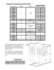
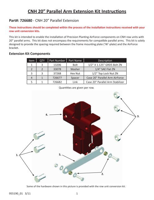
<strong>CNH</strong> 20” <strong>Parallel</strong> <strong>Arm</strong> <strong>Extension</strong> <strong>Kit</strong> <strong>Instructions</strong>Part#: 726680 - <strong>CNH</strong> 20” <strong>Parallel</strong> <strong>Extension</strong>These instructions should be completed within the process of the installation instructions received with yourrow unit conversion kits.This kit is intended to enable the installation of <strong>Precision</strong> <strong>Planting</strong> AirForce components on <strong>CNH</strong> row units with20” parallel arms. This kit does not encompass the requirements for compatible parallel arms. This kit is solelydesigned to provide the spacing required between the frame mounting plate (‘W’-plate) and the AirForcebracket.<strong>Extension</strong> <strong>Kit</strong> ComponentsItem QTY Part Number Part Name Description1 3 13206 Bolt 1/2" X 1.125" GRD5 Bolt ZN2 2 33078 Washer 1/4" SAE Flat ZN3 3 37268 Hex Nut 1/2" Top Lock Nut ZN4 1 726677 Spacer Case 20" <strong>Parallel</strong> <strong>Arm</strong> AirForce5 1 726682 Link Case 20" <strong>Parallel</strong> <strong>Arm</strong> StabilizerQuantities are given per row.4.3.1.5.2.Some of the hardware shown in this picture is provided with the row unit conversion kit.955190_01 3/11 1
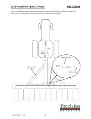
<strong>CNH</strong> 20” <strong>Parallel</strong> <strong>Arm</strong> <strong>Extension</strong> <strong>Kit</strong> <strong>Instructions</strong> (Continued)Part#: 726680 - <strong>CNH</strong> 20” <strong>Parallel</strong> <strong>Extension</strong>These steps should be completed between steps 1 and 2 of the row unit conversion instructions.Once the row unit is ready to accept new components, begin by installing the <strong>CNH</strong> 20” <strong>Parallel</strong> <strong>Arm</strong> Spacer(726677) onto the planter frame using the 1/2” X 1.125” GRD5 Bolts (13206). Note the multiple mountinglocations available on the Case Air Spring Head Mount (726672); to facilitate mounting to various ‘W’ platedesigns. The images in the primary instructions reference a ‘W’ plate with the mounting locationsvertically aligned in the center of the plate, you should use the recommended holes for your ‘W’ plate design.The 726677 Spacer bracket will be installed onto the ‘W’ plate so that the Head Mount bracket may beproperly installed.Secure the 726677 Spacer bracket to the ‘W’ plate using the three provided ½” X 1.125” GRD5 Bolts and ½”Top Lock Hex Nuts.At this point continue with the primary row unit conversion instructions at step #2, with the exception ofinstalling the Case Air Spring Head Mount (726672) onto the 726677 Spacer bracket instead of the ‘W’ plateas stated.Install 726677 Spacer Bracketbetween components hereCase Air Spring Head Mount (726672) Case Air Spring Head Mount (726672)and 1/2” X 1.125” GRD5 Bolts (13206)Complete Row Unit Conversion955190_01 3/11 2
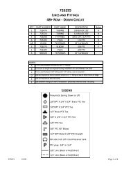
<strong>CNH</strong> 20” <strong>Parallel</strong> <strong>Arm</strong> <strong>Extension</strong> <strong>Kit</strong> <strong>Instructions</strong> (Continued)Part#: 726680 - <strong>CNH</strong> 20” <strong>Parallel</strong> <strong>Extension</strong>Continue with these instructions in place of step #5 of the primary instructions.Install the Case 20” <strong>Parallel</strong> <strong>Arm</strong> Stabilizer Link between the Air Spring Head Mount (726672) and the Air SpringBase Mount (726673). Use the Stabilizer Link provided with this kit in place of the Case 14” <strong>Parallel</strong> <strong>Arm</strong>Stabilizer Link provided with the conversion kit. Secure the Stabilizer Link using the hardware supplied withrow unit conversion kits:Two – ¼” X 1” GRD 5 Bolt ZN (13005)Three – ¼” SAE Flat Washers (33078)Two – ¼” Top Lock Nut ZN (37260)Two – ¼”ID X ½”OD X 0.23”L Bushings (726574)Note: two washers are required for installation. A third washer is included in the hardware pack for theconversion kit, two additional washers are included within this kit. These washers may be used to shim out thelink as necessary to improve alignment and provide clearance around the cast link arm (installed behindStabilizer Link on Head Mount casting).Install additionalwashers as necessary.RequiredAt this point continue with the primary row unit conversion instructions at step #6.955190_01 3/11 3