RowFlow Quick Reference Guide - Precision Planting
RowFlow Quick Reference Guide - Precision Planting
RowFlow Quick Reference Guide - Precision Planting
- No tags were found...

You also want an ePaper? Increase the reach of your titles
YUMPU automatically turns print PDFs into web optimized ePapers that Google loves.
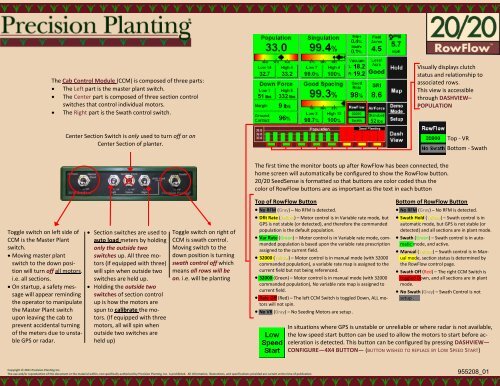
The Cab Control Module (CCM) is composed of three parts: The Left part is the master plant switch. The Center part is composed of three section controlswitches that control individual motors. The Right part is the Swath control switch.Visually displays clutchstatus and relationship toassociated rows.This view is accessiblethrough DASHVIEW–POPULATIONCenter Section Switch is only used to turn off or onCenter Section of planter.Top - VRBottom - SwathToggle switch on left side ofCCM is the Master Plantswitch. Moving master plantswitch to the down positionwill turn off all motors.i.e. all sections. On startup, a safety messagewill appear remindingthe operator to manipulatethe Master Plant switchupon leaving the cab toprevent accidental turningof the meters due to unstableGPS or radar. Section switches are used toauto load meters by holdingonly the outside twoswitches up. All three motors(if equipped with three)will spin when outside twoswitches are held up. Holding the outside twoswitches of section controlup is how the motors arespun to calibrate the motors.(If equipped with threemotors, all will spin whenoutside two switches areheld up)Toggle switch on right ofCCM is swath control.Moving switch to thedown position is turningswath control off whichmeans all rows will beon. i.e. will be plantingThe first time the monitor boots up after <strong>RowFlow</strong> has been connected, thehome screen will automatically be configured to show the <strong>RowFlow</strong> button.20/20 SeedSense is formatted so that buttons are color coded thus thecolor of <strong>RowFlow</strong> buttons are as important as the text in each buttonTop of <strong>RowFlow</strong> Button No RFM (Gray) – No RFM is detected. Dflt Rate (YellowYellow) – Motor control is in Variable rate mode, butGPS is not stable (or detected), and therefore the commandedpopulation is the default population. Var Rate (Green) – Motor control is in Variable rate mode, commandedpopulation is based upon the variable rate prescriptionassigned to the current field. 32000 (Yellow) – Motor control is in manual mode (with 32000commanded population), a variable rate map is assigned to thecurrent field but not being referenced. 32000 (Green) – Motor control is in manual mode (with 32000commanded population), No variable rate map is assigned tocurrent field. Rate Off (Red) – The left CCM Switch is toggled Down, ALL motorswill not spin. No VR (Gray) – No Seeding Motors are setup .Bottom of <strong>RowFlow</strong> Button No RFM (Gray) – No RFM is detected. Swath Hold (Yellow) – Swath control is inautomatic mode, but GPS is not stable (ordetected) and all sections are in plant mode. Swath (Green) – Swath control is in automaticmode, and active. Manual (Yellow) – Swath control is in Manualmode, section status is determined bythe <strong>RowFlow</strong> control page. Swath Off (Red) – The right CCM Switch istoggled Down, and all sections are in plantmode. No Swath (Gray) – Swath Control is notsetup .In situations where GPS is unstable or unreliable or where radar is not available,the low speed start button can be used to allow the motors to start before accelerationis detected. This button can be configured by pressing DASHVIEW—CONFIGURE—4X4 BUTTON— (BUTTON WISHED TO REPLACE BY LOW SPEED START)Copyright © 2011 <strong>Precision</strong> <strong>Planting</strong> Inc.The use and/or reproduction of this document or the material within, not specifically authorized by <strong>Precision</strong> <strong>Planting</strong>, Inc. is prohibited. All information, illustrations, and specifications provided are current at the time of publication.955208_01
<strong>RowFlow</strong> Setup page is where you will find the basic information on the configuration of yourplanter. It lists the number of motors configured and the number of swath sections that are set up.It also gives a visual of how the planter is configured based on the GPS measurements, planter info,and swath and motor configurations. It is accessible by going to SETUP—SYSTEMS—ROWFLOWSETUP.Motor ConfigurationShows the number of motors configuredfor the planter. Takes you to Motor Setuppage.Swath ConfigurationShows the number of swath sections forthe planter. Takes you to Swath SectionSetup page.Planter DiagramThe diagram in the middle of the Setuppage shows how your planter is configuredbased on the number of rows andspacing entered in the planter info and themeasurements entered in the GPS offsets.THIS DIAGRAM SHOULD LOOK LIKE YOURPLANTER.Swath and Motor DiagramThe bottom diagram on the Setup pageshows the configuration of your clutchesand motors and the rows associated witheach.Use the Frame Type button to select your planter frame.Also use the Hitch Style button to select your Hitch typeThe four boxes at the bottom ofthe tractor page in GPS setup arefor the measurements for theGPS to know where the receiveris located on the tractor. It needsfollowing measurements—A. Center of rear axle to pivotpoint of planter hitch.B. Receiver to center of tractor.C. Receiver to center of rearaxle.D. Receiver to the ground.Note: If the receiver is on the oppositeside of the tractor from what is shown, itcan be flipped to the other side with theflip button next to where measurementsare entered.RFM mounting positions:The RFM Direction button takes to you the page where you are able to selectthe orientation of the RFM on the planter. The RFM may be mounted horizontallyat a right angle to the planter bar with the label up or down and the portsfacing to the left, right, rear, or front of the planter. It also may be mountedvertically with the ports down and the label facing toward the left, right, rear, orfront of the planter. In any of these positions, the RFM must be mounted within5° of level both horizontally and vertically.Copyright © 2011 <strong>Precision</strong> <strong>Planting</strong> Inc.The use and/or reproduction of this document or the material within, not specifically authorized by <strong>Precision</strong> <strong>Planting</strong>, Inc. is prohibited. All information, illustrations, and specifications provided are current at the time of publication.Specific measurements need to be taken to ensure accurateswath control and mapping of seed drop. Precise measurementsare needed of the following distances—A. Distance from pivot of hitch to center of lift wheels with the planter lowered.B. Distance from pivot of hitch to shortest seed exit with the planter lowered (end of seed tube).C. Distance from pivot of hitch to longest seed exit with the planter lowered (end of seed tube).D. Distance from center of front frame rows to centerline of planter.E. Distance from center of rear frame rows to centerline of planter.Note: For 3-point planters, center of rear axle is used in place of pivot of hitch955208_01
Variable RateThe left side of the <strong>RowFlow</strong> controlpage is the variable rate controls. Whenenabled, the operator is able to see whatthe current population is and what thenext population is going to be. Whenvariable rate is in manual mode, the mapwill disappear and up to eight presetpopulations will appear. From these, theoperator can manually select a population.The <strong>RowFlow</strong> Control page is the home for controlling preferences on how<strong>RowFlow</strong> controls population and swath coverage. The operator can changewhat aspects of the map row clutches will be controlled to or manually runthe clutches using the two arrows or the manual section button that appearswhen swath is disabled. It is also where the operator can change from variablerate to manual rate population changes. The <strong>RowFlow</strong> control page isreached by pressing the ROWFLOW button on the homepage.Control PlanPressing the control plan button will allow the operator toselect which aspects of the map <strong>RowFlow</strong> will activateclutches for. When Swath Control is in manual mode, thisbutton changes to MANUALSECTION CONTROL and bringsup a screen as shown tocontrol the clutch sections.While in the <strong>RowFlow</strong> control page,it is still possible to see what thepopulation, singulation, and spacingare of the planter.AutoMap ExpressOperator may create a new prescription or edit an existing prescription.To create a new prescription: Press AUTOMAP EXPRESS Field boundary must be loaded or created (see Advanced Swath for details) A USB drive with USDA soil data for correct county on it inserted into 20/20display Press GET USDA SOIL DATA FOR FIELD. Once the soil data is loaded, prescriptionwill need to be edited. To edit the prescription for each soil type, press on the soil type and then pressthe -500 or +500 buttons at the bottom of the screen until desired populationis reached. Note: if it is desired to change all populations by the same amount, all soil types may beselected by pressing SELECT ALL SOIL TYPESAdvanced Swath ToolsAdvanced Swath is for creating boundaries and simulatedheadlands while in field.To create a field boundary: Press the ADVANCED SWATH TOOLS then BOUNDARY. Enter the offset distance from the center of tractor to theedge of planter by pressing the SETUP OFFSET button. Makesure that the offset is to the correct side of the planter (ie.closest to field edge) Position the planter at the edge of the field as if to plantthe outside round and press the RECORD FIELD BOUNDARY. Plant the outside round of the field and press END FIELDBOUNDARY when finished. Advanced Swath will connect andcreate field boundary. Note: if at any time during this process, it is necessary to stopplanting the outside round, the recording may be paused with thePAUSE button and then resumed by pressing the RESUME button(PAUSE button changes to RESUME).To create a simulated headland: Press ADVANCED SWATH then HEADLANDS. Enter the desired Headland width and press create headlandfor field boundary and inner boundary as desired.RTK Quality GPS is strongly recommended to maintain accurateboundaries and clutch shutoffs for headlands.Copyright © 2011 <strong>Precision</strong> <strong>Planting</strong> Inc.The use and/or reproduction of this document or the material within, not specifically authorized by <strong>Precision</strong> <strong>Planting</strong>, Inc. is prohibited. All information, illustrations, and specifications provided are current at the time of publication.955208_01
Swath Control The Swath Control box shows the current state ofeach clutch that is plugged into the RFM base harness.Tap the Legend to see what all the colors indicate. When each clutch is activated, it will place a whitebox around the clutch as shown. It is not a signal thatsomething is wrong but is showing it is working correctly. Tapping on the Swath Control box will show theaverage seeding delays for the last 10 and 50 cyclesof each row clutch.Lift SwitchShows the status of the lift switch and what percentagethe switch is at. Note: with Rotary HeightSensors, this is important to note what percentagethe switch is at for each planter position—lowered,lifted, planter engaged.Serial OutWhen using a serial motor, the motor drive boxshould be ignored and the serial box will be used tosee what the commanded population is. Note: Forserial motors, the 20/20 can only tell the AccuRatecontroller what speed to spin the motors and has noinformation on what the motors are actually doing,thus no diagnostics exist for serial motors.<strong>RowFlow</strong> Ctl ModuleShows communication status and currentvoltageSpeedShows GPS and Radar MPH and the whiteP shows which is primaryPower InputShows the voltage and draw of the twopower legs of the RFM and the voltage ofCAN and sensor. Note: press each powerleg to see what each leg is providing powerto.The <strong>RowFlow</strong> Diagnostics page shows current data on how the componentsof <strong>RowFlow</strong> are performing and what may be causing problems.It is the starting point for diagnosing problems with <strong>RowFlow</strong>.To reach this page, press SETUP—DIAGNOSE—ROWFLOW. The firstpage shown in <strong>RowFlow</strong> Diagnostics is the diagnostic page for thefirst RFM. If the planter is equipped with two RFM’s, press the downarrow on the right side to see diagnostics for the second RFM.Copyright © 2011 <strong>Precision</strong> <strong>Planting</strong> Inc.The use and/or reproduction of this document or the material within, not specifically authorized by <strong>Precision</strong> <strong>Planting</strong>, Inc. is prohibited. All information, illustrations, and specifications provided are current at the time of publication.Health Checks<strong>RowFlow</strong> has five Health Checks that anoperator can run to troubleshoot problems. Setup/Wiring—Checks the setup of thesystem and if the wiring is working correctly. Manual Swath—Cycles through all theswath sections and user listens to see ifthe system passes or fails. Voltage/Current—Cycles power to themotors and clutches to check the stabilityof the electrical system. Motor Stability—Drive motors at 3mphand 7mph and checks the stability of themotors at the different speeds. RFM Direction— Checks the RFM directionby starting and stopping the planter.Motor Drive DiagnosticsThe Motor Drive box shows what the motors are currently doing and what the 20/20 is commanding of the motors. PWM—Pulse Width Modulation—Commands signal to hydraulic motors: can be used as duty cycle of control solenoid. Act RPM—Actual RPM—Number of revolutions per minute each motor is actually turning. Cmd RPM—How fast the 20/20 is commanding the motor to turn. If this does not match Act RPM, there may be a problem with the speedsensor or the hydraulic system of the tractor. Cmd Pop—What the commanded population is for each motor. Next Pop—The next population for each motor. Dist. (ft) - Distance to the next population change and counts down from 200 ft. Stability, Avg. Err., Abs. Err, - All three are measures of the stability of the motors and can be seen by pressing on any of the three. If themotors fail, it is normally due to a hydraulic system problem or too slow motor RPM.955208_01