
You also want an ePaper? Increase the reach of your titles
YUMPU automatically turns print PDFs into web optimized ePapers that Google loves.
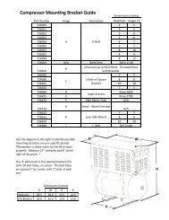
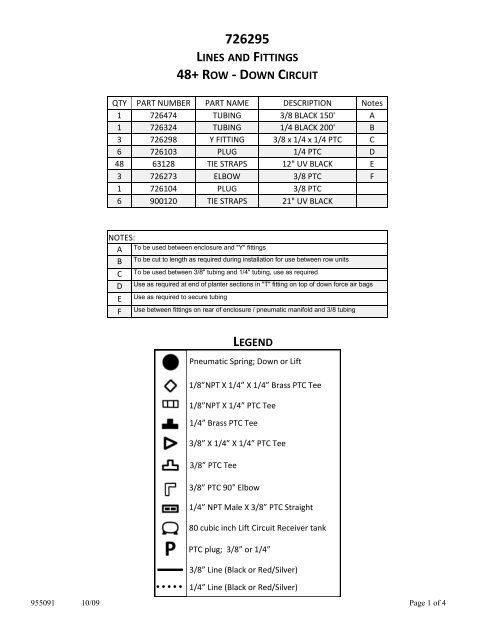
726295LINES AND FITTINGS<strong>48+</strong> ROW - DOWN CIRCUITQTY PART NUMBER PART NAME DESCRIPTION Notes1 726474 TUBING 3/8 BLACK 150' A1 726324 TUBING 1/4 BLACK 200' B3 726298 Y FITTING 3/8 x 1/4 x 1/4 PTC C6 726103 PLUG 1/4 PTC D48 63128 TIE STRAPS 12" UV BLACK E3 726273 ELBOW 3/8 PTC F1 726104 PLUG 3/8 PTC6 900120 TIE STRAPS 21" UV BLACKNOTES:ABCDEFTo be used between enclosure and "Y" fittingsTo be cut to length as required during installation for use between row unitsTo be used between 3/8" tubing and 1/4" tubing, use as requiredUse as required at end of planter sections in "T" fitting on top of down force air bagsUse as required to secure tubingUse between fittings on rear of enclosure / pneumatic manifold and 3/8 tubingLEGENDPneumatic Spring; <strong>Down</strong> or Lift1/8”NPT X 1/4” X 1/4” Brass PTC Tee1/8”NPT X 1/4” PTC Tee1/4” Brass PTC Tee3/8” X 1/4” X 1/4” PTC Tee3/8” PTC Tee3/8” PTC 90° Elbow1/4” NPT Male X 3/8” PTC Straight80 cubic inch Lift Circuit Receiver tankPTC plug; 3/8” or 1/4”3/8” Line (Black or Red/Silver)1/4” Line (Black or Red/Silver)955091 10/09 Page 1 of 4
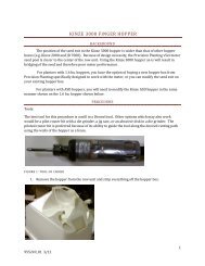
Plumbing InstallationThis process should be done with the planter raised, halffolded for transport, and the row units fully extended down.The following pages contain images of suggested methods of routing the air lines for your new 20/20 Air-Force. Due to the wide variety of planter/row unit configurations and accessories available, you shouldadapt the installation as necessary for your planter. The primary concern is the security of the lines themselves.The lines should be fastened to the planter in a manner that allows full range of motion/clearanceof the row unit. Special caution should be taken around rows at break or fold points of the planter as itfolds to and unfolds from transport mode. Extra lengths of slack or alternative routing may be necessary.The supplied fittings should have pre-existing thread sealant - ready to install - for ease ofinstallment. Always use Thread Tape when installing air fittings that do not have thisBlack Tubing - used for the <strong>Down</strong> Force CircuitRed / Silver Tubing - used for the Lift Force Circuit3/8” lines (Black or Red/Silver) - used for the main line from the Compressor Module togroups of rows, usually on the main draw bar of the planter1/4” lines (Black or Red/Silver) - used from the main line to and between the individualrow unit Air BagsSecure the Air Lines using the supplied zip tie-straps - do not pinch the line closed whencinching tightThe 1/4” lines should be routed back to and secured to the main bar or to existing bundlesof wires/hoses of the planter between row unitsMost 30” row configurations should need between 34 to 42 inches of 1/4” line between<strong>Down</strong> Force Air Bags. Do not pre-cut the line, measure lay-out each length individually.Lift Circuit kits containing 1 extra brass 1/4” PTC Tee per row will require lengths of the1/4” line from the connector on top of the Lift Bag to the 1/4”PTC Tee placed on the mainDraw Bar.All Lift Circuits will require the use of one or multiple 80 cubic inch Air Receiver Assembliesalong the 3/8” line. These are used to dissipate the force created in the Lift circuitas the planter is raised and the weight of the row unit is transferred to the Lift bags.The color of the tubing is for ease of circuit identity only and has no bearing on capacities.After completion of the FIRST row and PRIOR to continuing to other rows, check for clearance of, andlack of pinch points on all lines and fittings. This should be done by completely raising and lowering theplanter to flex the row unit through it entire range of motion.955091 10/09 Page 2 of 4
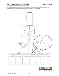
<strong>Row</strong> Configuration:Transport/ Fold:<strong>48+</strong> row, any spacingFront Fold955091 10/09 Page 3 of 4
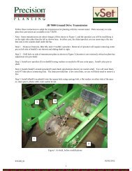
PART NUMBER DESCRIPTION726506 PTC 1/4 TURN VALVE (VENTED)726507 PTC 3/8 TURN VALVE (VENTED)<strong>Row</strong> Configuration:Transport/ Fold:Route the lines for the interplant rows separate from the ‘Corn’rows. This allows easy removal of the rows from the circuit whenthey are locked up: 1)Remove the 3/8” line from the rear of thecompressor manifold and plug the port, or 2) Install a valve in theline to remove the circuit from pressure. (see diagram and partnumber info above left)47<strong>Row</strong>, Split <strong>Row</strong>Front Fold955091 10/09 Page 4 of 4