JD 7000 Ground Drive Transmission - Precision Planting
JD 7000 Ground Drive Transmission - Precision Planting
JD 7000 Ground Drive Transmission - Precision Planting

Create successful ePaper yourself
Turn your PDF publications into a flip-book with our unique Google optimized e-Paper software.
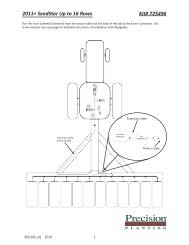
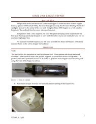
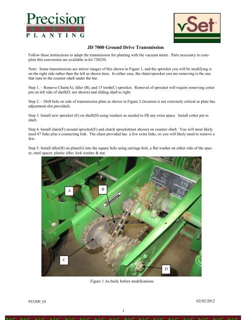
<strong>JD</strong> <strong>7000</strong> <strong>Ground</strong> <strong>Drive</strong> <strong>Transmission</strong>Follow these instructions to adapt the transmission for planting with the vacuum meter. Parts necessary to completethis conversion are available in kit 730230.Note: Some transmissions are mirror images of this shown in Figure 1, and the sprocket you will be modifying ison the right side rather than the left as shown here. In either case, the chain/sprocket you are removing is the onethat runs to the counter-shaft under the bar.Step 1. – Remove Chain(A), Idler (B), and 15 tooth(C) sprocket. Removal of sprocket will require removing cotterpin on left side of shaft(D, not shown) and sliding shaft to right.Step 2. – Drill hole on side of transmission plate as shown in Figure 2.(location is not extremely critical as plate hasadjustment slot provided).Step 3. Install new sprocket (E) on shaft(D) using washers as needed to fill any extra space. Install cotter pin inshaft.Step 4. Install chain(F) around sprocket(E) and clutch sprocket(not shown) on counter-shaft. You will most likelyneed 47 links plus a connecting link. The chain provided has a few extra links, so you will likely need to remove afew.Step 5. Install idler(H) on plate(G) into the square hole using carriage bolt, a flat washer on either side of the spacer,steel spacer, plastic idler, lock washer & nut.ABCDFigure 1 As-built, before modifications955209_0102/02/20121
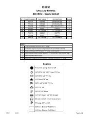
Step 6. Install plate(G) on to left plate of transmission, attaching slotted side through hole drilled in (step2)with carriage bolt, lock washer, and nut. Be sure idler is on bottom side of chain as shown in Figure 3.Step 7. Adjust tension in chain by sliding plate/idler up or down in slot.2.5”Drill 3/8” clearance holehere2”FIGURE 2 LEFT SIDE VIEW OF TRANSMISSION PLATE SHOWING HOLE LOCATIONFGHED955209_0102/02/20122