214-Pin Micro-DIMM-DDR2-SDRAM Modules MDIMM DDR2 ... - UBiio
214-Pin Micro-DIMM-DDR2-SDRAM Modules MDIMM DDR2 ... - UBiio
214-Pin Micro-DIMM-DDR2-SDRAM Modules MDIMM DDR2 ... - UBiio

You also want an ePaper? Increase the reach of your titles
YUMPU automatically turns print PDFs into web optimized ePapers that Google loves.
November 2006HYS64T32000HM–[3S/3.7/5]–AHYS64T64020HM–[3S/3.7/5]–A<strong>214</strong>-<strong>Pin</strong> <strong>Micro</strong>-<strong>DIMM</strong>-<strong>DDR2</strong>-<strong>SDRAM</strong> <strong>Modules</strong>M<strong>DIMM</strong><strong>DDR2</strong> <strong>SDRAM</strong>RoHS CompliantInternet Data SheetRev. 1.11
Internet Data SheetHYS64T[32/64]0[0/2]0HM–[3S/3.7/5]–A<strong>Micro</strong>-<strong>DIMM</strong> <strong>DDR2</strong> <strong>SDRAM</strong> <strong>Modules</strong>HYS64T32000HM–[3S/3.7/5]–A, HYS64T64020HM–[3S/3.7/5]–ARevision History: 2006-11, Rev. 1.11PageSubjects (major changes since last revision)All Qimonda updateAll Adapted internet editionPrevious Revision: 2005-10, Rev. 1.1All Added -3SPrevious Revision: 2004-10, 1.0We Listen to Your CommentsAny information within this document that you feel is wrong, unclear or missing at all?Your feedback will help us to continuously improve the quality of this document.Please send your proposal (including a reference to this document) to:techdoc@qimonda.comqag_techdoc_rev400 / 3.2 QAG / 2006-08-07 203062006-HT1R-Z2PY
Internet Data SheetHYS64T[32/64]0[0/2]0HM–[3S/3.7/5]–A<strong>Micro</strong>-<strong>DIMM</strong> <strong>DDR2</strong> <strong>SDRAM</strong> <strong>Modules</strong>1 OverviewThis chapter gives an overview of the 1.8 V <strong>214</strong>-<strong>Pin</strong> <strong>Micro</strong>-<strong>DIMM</strong>-<strong>DDR2</strong>-<strong>SDRAM</strong> <strong>Modules</strong> product family and describes itsmain characteristics.1.1 Features• <strong>214</strong>-<strong>Pin</strong> PC2-5300, PC2-4200 and PC2-3200 <strong>DDR2</strong><strong>SDRAM</strong> memory modules for use as main memory wheninstalled in systems such as mobile personal computers.• 32M × 64and 64M × 64 module organization, and 32M× 16 chip organization• Standard Double-Data-Rate-Two Synchronous DRAMs(<strong>DDR2</strong> <strong>SDRAM</strong>) with a single + 1.8 V (± 0.1 V) powersupply• 256MB and 512MB modules built with 512Mb <strong>DDR2</strong><strong>SDRAM</strong>s in P-TFBGA-84 chipsize packages• Programmable CAS Latencies (3, 4 and 5), Burst Length(8 & 4) and Burst Type• Burst Refresh, Distributed Refresh and Self Refresh• All inputs and outputs SSTL_1.8 compatible• Off-Chip Driver Impedance Adjustment (OCD) and On-DieTermination (ODT)• Serial Presence Detect with E 2 PROM• M<strong>DIMM</strong> Dimensions (nominal): 30 mm high, 54.0 mmwide• Based on standard reference layouts Raw Cards:“A” and “B”• 2-piece type Mezzanine Socket with 0,4 mm contactcenters• RoHS Compliant Products 1) TABLE 1Performance TableProduct Type Speed Code –3S –3.7 –5 UnitSpeed GradePC2–53005–5–5PC2–42004–4–4PC2–32003–3–3Max. Clock Frequency @CL5 f CK5 333 266 200 MHz@CL4 f CK4 266 266 200 MHz@CL3 f CK3 200 200 200 MHzMin. RAS-CAS-Delay t RCD 15 15 15 nsMin. Row Precharge Time t RP 15 15 15 nsMin. Row Active Time t RAS 45 45 40 nsMin. Row Cycle Time t RC 60 60 55 ns—1) RoHS Compliant Product: Restriction of the use of certain hazardous substances (RoHS) in electrical and electronic equipment as definedin the directive 2002/95/EC issued by the European Parliament and of the Council of 27 January 2003. These substances include mercury,lead, cadmium, hexavalent chromium, polybrominated biphenyls and polybrominated biphenyl ethers.Rev. 1.11, 2006-11 303062006-HT1R-Z2PY
Internet Data SheetHYS64T[32/64]0[0/2]0HM–[3S/3.7/5]–A<strong>Micro</strong>-<strong>DIMM</strong> <strong>DDR2</strong> <strong>SDRAM</strong> <strong>Modules</strong>1.2 DescriptionThe QIMONDA HYS64T[32/64]0[0/2]0HM–[3S/3.7/5]–Amodule family are Unbuffered <strong>Micro</strong>-<strong>DIMM</strong> modules“M<strong>DIMM</strong>s” with 30 mm height based on <strong>DDR2</strong> technology.<strong>DIMM</strong>s are available as non-ECC modules in 32M × 64(256 MB) and 64M × 64 (512 MB) organization and density,intended for mounting into <strong>214</strong>-pin mezzanine connectorsockets.The memory array is designed with 512-Mbit Double-Data-Rate-Two (<strong>DDR2</strong>) Synchronous DRAMs. Decouplingcapacitors are mounted on the PCB board. The <strong>DIMM</strong>sfeature serial presence detect based on a serial E 2 PROMdevice using the 2-pin I 2 C protocol. The first 128 bytes areprogrammed with configuration data and are write protected;the second 128 bytes are available to the customer.Product Type 1)Compliance Code 2)TABLE 2Ordering Informationfor RoHS Compliant ProductsDescription<strong>SDRAM</strong>TechnologyPC2-5300HYS64T32000HM-3S-A 256MB 1R×16 PC2–5300M–555–12–B1 1 rank, Non-ECC 512 Mbit (×16)HYS64T64020HM-3S-A 512MB 2R×16 PC2–5300M–555–12–A1 2 ranks, Non-ECC 512 Mbit (×16)PC2–4200HYS64T32000HM–3.7–A 256MB 1R×16 PC2–4200M–444–12–B1 1 rank, Non-ECC 512 Mbit (×16)HYS64T64020HM–3.7–A 512MB 2R×16 PC2–4200M–444–12–A1 2 ranks, Non-ECC 512 Mbit (×16)PC2–3200HYS64T32000HM–5–A 256MB 1R×16 PC2–3200M–333–12–B1 1 rank, Non-ECC 512 Mbit (×16)HYS64T64020HM–5–A 512MB 2R×16 PC2–3200M–333–12–A1 2 ranks, Non-ECC 512 Mbit (×16)1) All Product Type numbers end with a place code, designating the silicon die revision. Example: HYS64T32000HM–3.7–A, indicating Rev.“A” dies are used for <strong>DDR2</strong> <strong>SDRAM</strong> components. For all QIMONDA <strong>DDR2</strong> module and component nomenclature see Chapter 6 of thisdata sheet.2) The Compliance Code is printed on the module label and describes the speed grade, for example “PC2–4200M–444–12–B1”, where4200M means Unbuffered <strong>Micro</strong>-<strong>DIMM</strong> modules with 4.26 GB/sec Module Bandwidth and “444-11” means Column Address Strobe (CAS)latency = 4, Row Column Delay (RCD) latency = 4 and Row Precharge (RP) latency = 4 using the latest JEDEC SPD Revision 1.2 andproduced on the Raw Card “B”.Rev. 1.11, 2006-11 403062006-HT1R-Z2PY
Internet Data SheetHYS64T[32/64]0[0/2]0HM–[3S/3.7/5]–A<strong>Micro</strong>-<strong>DIMM</strong> <strong>DDR2</strong> <strong>SDRAM</strong> <strong>Modules</strong>2 <strong>Pin</strong> ConfigurationThis chapter contains the pin configuration.2.1 <strong>Pin</strong> ConfigurationThe pin configuration of the <strong>DDR2</strong> <strong>SDRAM</strong> <strong>Micro</strong>-<strong>DIMM</strong> is listed by function in Table 5 (<strong>214</strong> pins). The abbreviations used incolumns <strong>Pin</strong> and Buffer Type are explained in Table 6 and Table 7 respectively. The pin numbering is depicted in Figure 1.TABLE 5<strong>Pin</strong> Configuration of M<strong>DIMM</strong>Ball No. Name <strong>Pin</strong>TypeBufferTypeFunctionClock Signals122 CK0 I SSTL Clock Signal CK 1:0, Complementary Clock Signal CK 1:0194 CK1 I SSTL123 CK0 I SSTL195 CK1 I SSTL43 CKE0 I SSTL Clock Enables 1:0147 CKE1 I SSTL Note: 2-rank moduleNC NC Not ConnectedNote: 1-rank moduleControl Signals165 S0 I SSTL Chip Select Rank 1:062 S1 I SSTL Note: 2-rank module.NC NC Not ConnectedNote: 1-rank module163 RAS I Row Address Strobe (RAS), Column Address Strobe (CAS), Write60 CAS I SSTL Enable (WE)56 WE I SSTLAddress Signals55 BA0 I SSTL Bank Address Bus 1:0162 BA1 I SSTL46 BA2 I SSTL Bank Address Bus 2Note: Greater than 512Mb <strong>DDR2</strong> <strong>SDRAM</strong>SNC NC – Not ConnectedNote: Less than 1Gb <strong>DDR2</strong> <strong>SDRAM</strong>SRev. 1.11, 2006-11 603062006-HT1R-Z2PY
Internet Data SheetHYS64T[32/64]0[0/2]0HM–[3S/3.7/5]–A<strong>Micro</strong>-<strong>DIMM</strong> <strong>DDR2</strong> <strong>SDRAM</strong> <strong>Modules</strong>Ball No. Name <strong>Pin</strong>TypeBufferTypeFunction161 A0 I SSTL Address Inputs 12:0, Address Input 10/Autoprecharge159 A1 I SSTL52 A2 I SSTL158 A3 I SSTL51 A4 I SSTL50 A5 I SSTL157 A6 I SSTL48 A7 I SSTL155 A8 I SSTL154 A9 I SSTL54 A10 I SSTLAP I SSTL47 A11 I SSTL153 A12 I SSTL167 A13 I SSTL Address Input 13Note: <strong>Modules</strong> based on ×4/×8 componentNC NC – Not ConnectedNote: <strong>Modules</strong> based on ×16 componentData Signals3 DQ0 I/O SSTL Data Bus 0:384 DQ1 I/O SSTL Note: Data Input/Output pins9 DQ2 I/O SSTL10 DQ3 I/O SSTL109 DQ4 I/O SSTL110 DQ5 I/O SSTL114 DQ6 I/O SSTL115 DQ7 I/O SSTL12 DQ8 I/O SSTLRev. 1.11, 2006-11 703062006-HT1R-Z2PY
Internet Data SheetHYS64T[32/64]0[0/2]0HM–[3S/3.7/5]–A<strong>Micro</strong>-<strong>DIMM</strong> <strong>DDR2</strong> <strong>SDRAM</strong> <strong>Modules</strong>Ball No. Name <strong>Pin</strong>TypeBufferTypeFunction13 DQ9 I/O SSTL Data Bus 0:3821 DQ10 I/O SSTL Note: Data Input/Output pins22 DQ11 I/O SSTL117 DQ12 I/O SSTL118 DQ13 I/O SSTL125 DQ14 I/O SSTL126 DQ15 I/O SSTL24 DQ16 I/O SSTL25 DQ17 I/O SSTL30 DQ18 I/O SSTL31 DQ19 I/O SSTL128 DQ20 I/O SSTL129 DQ21 I/O SSTL133 DQ22 I/O SSTL134 DQ23 I/O SSTL33 DQ24 I/O SSTL34 DQ25 I/O SSTL38 DQ26 I/O SSTL39 DQ27 I/O SSTL136 DQ28 I/O SSTL137 DQ29 I/O SSTL142 DQ30 I/O SSTL143 DQ31 I/O SSTL67 DQ32 I/O SSTL68 DQ33 I/O SSTL73 DQ34 I/O SSTL74 DQ35 I/O SSTL174 DQ36 I/O SSTL175 DQ37 I/O SSTL179 DQ38 I/O SSTL180 DQ39 I/O SSTL Data Bus 39:5776 DQ40 I/O SSTL77 DQ41 I/O SSTL81 DQ42 I/O SSTL82 DQ43 I/O SSTL182 DQ44 I/O SSTL183 DQ45 I/O SSTL188 DQ46 I/O SSTL189 DQ47 I/O SSTL84 DQ48 I/O SSTLRev. 1.11, 2006-11 803062006-HT1R-Z2PY
Internet Data SheetHYS64T[32/64]0[0/2]0HM–[3S/3.7/5]–A<strong>Micro</strong>-<strong>DIMM</strong> <strong>DDR2</strong> <strong>SDRAM</strong> <strong>Modules</strong>Ball No. Name <strong>Pin</strong>TypeBufferTypeFunctionEEPROM105 SCL I CMOS Serial Bus Clock104 SDA I/O OD Serial Bus Data211 SA0 I CMOS Serial Address Select Bus 1:0213 SA1 I CMOSPower Supplies1 V REF AI – I/O Reference Voltage42, 45, 49, 53,57, 61, 64, 146,149, 152, 156,160, 164, 168,171V DD PWR – Power Supply107 V DDSPD PWR – EEPROM Power Supply2, 5, 8, 11, 14,17, 20, 23, 26,29, 32, 35, 37,40, 66, 69, 72,75, 78, 80, 83,86, 89, 91, 94,97, 100, 103,108, 111, 113,116, 119, 121,124, 127, 130,132, 135, 138,141, 144, 173,176, 178, 181,184, 187, 190,193, 196, 205,199, 202, 207,210V SS GND – Ground PlaneOther <strong>Pin</strong>s166 ODT0 I SSTL On-Die Termination Control 1:0Note: 2-rank module63 ODT1 I SSTL On-Die Termination Control 1:0Note: 2-rank moduleNCNot ConnectedNote: 1-rank module15, 16, 41, 44,46, 58, 59, 65,87, 88, 106,145, 148, 150,151, 167, 169,170, 172, 212,<strong>214</strong>NC NC Not connectedRev. 1.11, 2006-11 1003062006-HT1R-Z2PY
Internet Data SheetHYS64T[32/64]0[0/2]0HM–[3S/3.7/5]–A<strong>Micro</strong>-<strong>DIMM</strong> <strong>DDR2</strong> <strong>SDRAM</strong> <strong>Modules</strong>AbbreviationIOI/OAIPWRGNDNCDescriptionStandard input-only pin. Digital levels.Output. Digital levels.I/O is a bidirectional input/output signal.Input. Analog levels.PowerGroundNot ConnectedTABLE 6Abbreviations for <strong>Pin</strong> TypeAbbreviationSSTLCMOSODDescriptionTABLE 7Abbreviations for Buffer TypeSerial Stub Terminated Logic (SSTL_18)CMOS LevelsOpen Drain. The corresponding pin has 2 operational states, active low and tristate, andallows multiple devices to share as a wire-OR.Rev. 1.11, 2006-11 1103062006-HT1R-Z2PY
Internet Data Sheet3 Electrical CharacteristicsHYS64T[32/64]0[0/2]0HM–[3S/3.7/5]–A<strong>Micro</strong>-<strong>DIMM</strong> <strong>DDR2</strong> <strong>SDRAM</strong> <strong>Modules</strong>This chapter lists the electrical characteristics.3.1 Absolute Maximum RatingsCaution is needed not to exceed absolute maximum ratings of the DRAM device listed in Table 8 at any time.TABLE 8Absolute Maximum RatingsSymbol Parameter Rating Unit NoteMin. Max.V DD Voltage on V DD pin relative to V SS –1.0 +2.3 V1)V DDQ Voltage on V DDQ pin relative to V SS –0.5 +2.3 V1)2)V DDL Voltage on V DDL pin relative to V SS –0.5 +2.3 V1)2)V IN , V OUT Voltage on any pin relative to V SS –0.5 +2.3 V1)T STG Storage Temperature –55 +100 °C1)2)1) When V DD and V DDQ and V DDL are less than 500 mV; V REF may be equal to or less than 300 mV.2) Storage Temperature is the case surface temperature on the center/top side of the DRAM.Attention: Stresses greater than those listed under “Absolute Maximum Ratings” may cause permanent damage tothe device. This is a stress rating only and functional operation of the device at these or any otherconditions above those indicated in the operational sections of this specification is not implied. Exposureto absolute maximum rating conditions for extended periods may affect reliability.TABLE 9DRAM Component Operating Temperature RangeSymbol Parameter Rating Unit NoteMin. Max.T OPER Operating Temperature 0 95 °C1)2)3)4)1) Operating Temperature is the case surface temperature on the center / top side of the DRAM.2) The operating temperature range are the temperatures where all DRAM specification will be supported. During operation, the DRAM casetemperature must be maintained between 0 - 95 °C under all other specification parameters.3) Above 85 °C the Auto-Refresh command interval has to be reduced to t REFI = 3.9 µs4) When operating this product in the 85 °C to 95 °C TCASE temperature range, the High Temperature Self Refresh has to be enabled bysetting EMR(2) bit A7 to “1”. When the High Temperature Self Refresh is enabled there is an increase of I DD6 by approximately 50%Rev. 1.11, 2006-11 1303062006-HT1R-Z2PY
Internet Data SheetHYS64T[32/64]0[0/2]0HM–[3S/3.7/5]–A<strong>Micro</strong>-<strong>DIMM</strong> <strong>DDR2</strong> <strong>SDRAM</strong> <strong>Modules</strong>3.2 DC Operating ConditionsThis chapter contains the DC operating conditions tables.TABLE 10Operating ConditionsParameter Symbol Values Unit NoteOperating temperature (ambient) T OPR 0 +65 °CDRAM Case Temperature T CASE 0 +95 °C1)2)3)4)Storage Temperature T STG – 50 +100 °CBarometric Pressure (operating & storage) PBar +69 +105 kPa5)Operating Humidity (relative) H OPR 10 90 %1) DRAM Component Case Temperature is the surface temperature in the center on the top side of any of the DRAMs.2) Within the DRAM Component Case Temperature Range all DRAM specifications will be supported3) Above 85 °C DRAM Case Temperature the Auto-Refresh command interval has to be reduced to t REFI = 3.9 µs4) When operating this product in the 85 °C to 95 °C T CASE temperature range, the High Temperature Self Refresh has to be enabled bysetting EMR(2) bit A7 to “1”. When the High Temperature Self Refresh is enabled there is an increase of I DD6 by approximately 50%.5) Up to 3000 m.Min.Max.TABLE 11Supply Voltage Levels and DC Operating ConditionsParameter Symbol Values Unit NoteMin. Typ. Max.Device Supply Voltage V DD 1.7 1.8 1.9 VOutput Supply Voltage V DDQ 1.7 1.8 1.9 V1)Input Reference Voltage V REF 0.49 × V DDQ 0.5 × V DDQ 0.51 × V DDQ V2)SPD Supply Voltage V DDSPD 1.7 — 3.6 VDC Input Logic High V IH(DC) V REF +0.125 — V DDQ +0.3 VDC Input Logic Low V IL (DC ) – 0.30 — V REF – 0.125 VIn / Output Leakage Current I L – 5 — 5 µA3)1) Under all conditions, V DDQ must be less than or equal to V DD2) Peak to peak AC noise on V REF may not exceed ± 2% V REF (DC).V REF is also expected to track noise in V DDQ .3) Input voltage for any connector pin under test of 0 V ≤ V IN ≤ V DDQ + 0.3 V; all other pins at 0 V. Current is per pinRev. 1.11, 2006-11 1403062006-HT1R-Z2PY
Internet Data SheetHYS64T[32/64]0[0/2]0HM–[3S/3.7/5]–A<strong>Micro</strong>-<strong>DIMM</strong> <strong>DDR2</strong> <strong>SDRAM</strong> <strong>Modules</strong>3.3 Timing CharacteristicsThis chapter describes the AC characteristics.3.3.1 Speed Grade DefinitionsThis chapter contains the Speed Grade Definition tables.TABLE 12Speed Grade Definition Speed Bins for <strong>DDR2</strong>-667D, <strong>DDR2</strong>–533C and <strong>DDR2</strong>–400BSpeed Grade <strong>DDR2</strong>–667D <strong>DDR2</strong>–533C <strong>DDR2</strong>–400B Unit NoteQAG Sort Name –3S –3.7 –5CAS-RCD-RP latencies 5–5–5 4–4–4 3–3–3 t CKParameter Symbol Min. Max. Min. Max. Min. Max. —Clock Frequency @ CL = 3 t CK 5 8 5 8 5 8 ns1)2)3)4)@ CL = 4 t CK 3.75 8 3.75 8 5 8 ns1)2)3)4)@ CL = 5 t CK 3 8 3.75 8 5 8 ns1)2)3)4)Row Active Time t RAS 45 70000 45 70000 40 70000 ns1)2)3)4)5)Row Cycle Time t RC 60 — 60 — 55 — ns1)2)3)4)RAS-CAS-Delay t RCD 15 — 15 — 15 — ns1)2)3)4)Row Precharge Time t RP 15 — 15 — 15 — ns1)2)3)4)1) Timings are guaranteed with CK/CK differential Slew Rate of 2.0 V/ns. For DQS signals timings are guaranteed with a differential SlewRate of 2.0 V/ns in differential strobe mode and a Slew Rate of 1 V/ns in single ended mode. Timings are further guaranteed for normalOCD drive strength (EMRS(1) A1 = 0) only.2) The CK/CK input reference level (for timing reference to CK/CK) is the point at which CK and CK cross. The DQS/DQS, RDQS/RDQS,input reference level is the crosspoint when in differential strobe mode3) Inputs are not recognized as valid until V REF stabilizes. During the period before V REF stabilizes, CKE = 0.2 x V DDQ is recognized as low.4) The output timing reference voltage level is V TT .5) t RAS.MAX is calculated from the maximum amount of time a <strong>DDR2</strong> device can operate without a refresh command which is equal to 9 x t REFI .Rev. 1.11, 2006-11 1503062006-HT1R-Z2PY
Internet Data SheetHYS64T[32/64]0[0/2]0HM–[3S/3.7/5]–A<strong>Micro</strong>-<strong>DIMM</strong> <strong>DDR2</strong> <strong>SDRAM</strong> <strong>Modules</strong>3.3.2 Component AC Timing ParametersThis chapter contains the AC Timing Parameters.TABLE 13DRAM Component Timing Parameter by Speed Grade - <strong>DDR2</strong>–667Parameter Symbol <strong>DDR2</strong>–667 Unit Note1)2)3)4)5)6)7)8)Min. Max.DQ output access time from CK / CK t AC –450 +450 ps9)DQS output access time from CK / CK t DQSCK –400 +400 ps9)Average clock high pulse width t CH.AVG 0.48 0.52 t CK.AVG10)11)Average clock low pulse width t CL.AVG 0.48 0.52 t CK.AVG10)11)Average clock period t CK.AVG 3000 8000 psDQ and DM input setup time t DS.BASE 100 –– ps12)13)14)DQ and DM input hold time t DH.BASE 175 –– ps13)14)15)Control & address input pulse width for each input t IPW 0.6 — t CK.AVGDQ and DM input pulse width for each input t DIPW 0.35 — t CK.AVGData-out high-impedance time from CK / CK t HZ — t AC.MAX ps9)16)DQS/DQS low-impedance time from CK / CK t LZ.DQS t AC.MIN t AC.MAX ps9)16)DQ low impedance time from CK/CK t LZ.DQ 2xt AC.MIN t AC.MAX ps9)16)DQS-DQ skew for DQS & associated DQ signals t DQSQ — 240 ps17)CK half pulse width t HP Min(t CH.ABS ,t CL.ABS )__ps18)DQ hold skew factor t QHS — 340 ps19)DQ/DQS output hold time from DQS t QH t HP – t QHS — ps20)Write command to DQS associated clock edges WL RL–1 nCKDQS latching rising transition to associated clockedgest DQSS – 0.25 + 0.25 t CK.AVG21)DQS input high pulse width t DQSH 0.35 — t CK.AVGDQS input low pulse width t DQSL 0.35 — t CK.AVGDQS falling edge to CK setup time t DSS 0.2 — t CK.AVG21)DQS falling edge hold time from CK t DSH 0.2 — t CK.AVG21)Write postamble t WPST 0.4 0.6 t CK.AVGWrite preamble t WPRE 0.35 — t CK.AVGAddress and control input setup time t IS.BASE 200 — ps22)23)Address and control input hold time t IH.BASE 275 — ps23)24)Read preamble t RPRE 0.9 1.1 t CK.AVG25)26)Read postamble t RPST 0.4 0.6 t CK.AVG25)27)CAS to CAS command delay t CCD 2 — nCKWrite recovery time t WR 15 — ns28)Auto-Precharge write recovery + precharge time t DAL WR + t nRP — nCK29)30)Internal write to read command delay t WTR 7.5 — ns28)31)Rev. 1.11, 2006-11 1603062006-HT1R-Z2PY
Internet Data SheetHYS64T[32/64]0[0/2]0HM–[3S/3.7/5]–A<strong>Micro</strong>-<strong>DIMM</strong> <strong>DDR2</strong> <strong>SDRAM</strong> <strong>Modules</strong>Parameter Symbol <strong>DDR2</strong>–667 Unit Note1)2)3)4)5)6)7)8)Min. Max.Internal Read to Precharge command delay t RTP 7.5 — nsExit self-refresh to a non-read command t XSNR t RFC +10 — ns28)Exit self-refresh to read command t XSRD 200 — nCKExit precharge power-down to any valid t XP 2 — nCKcommand (other than NOP or Deselect)Exit power down to read command t XARD 2 — nCKExit active power-down mode to read command t XARDS 7 – AL — nCK(slow exit, lower power)CKE minimum pulse width ( high and low pulse t CKE 3 — nCK32)width)Mode register set command cycle time t MRD 2 — nCKMRS command to ODT update delay t MOD 0 12 ns28)OCD drive mode output delay t OIT 0 12 ns28)Minimum time clocks remain ON after CKEasynchronously drops LOWt DELAY t IS + t CK .AVG +t IH— ns1) For details and notes see the relevant Qimonda component data sheet2) V DDQ = 1.8 V ± 0.1V; V DD = 1.8 V ± 0.1 V. See notes 5)6)7)8)3) Timing that is not specified is illegal and after such an event, in order to guarantee proper operation, the DRAM must be powered downand then restarted through the specified initialization sequence before normal operation can continue.4) Timings are guaranteed with CK/CK differential Slew Rate of 2.0 V/ns. For DQS signals timings are guaranteed with a differential SlewRate of 2.0 V/ns in differential strobe mode and a Slew Rate of 1 V/ns in single ended mode.5) The CK / CK input reference level (for timing reference to CK / CK) is the point at which CK and CK cross. The DQS / DQS, RDQS / RDQS,input reference level is the crosspoint when in differential strobe mode.6) Inputs are not recognized as valid until V REF stabilizes. During the period before V REF stabilizes, CKE = 0.2 x V DDQ is recognized as low.7) The output timing reference voltage level is V TT .8) New units, ‘t CK.AVG ‘ and ‘nCK‘, are introduced in <strong>DDR2</strong>–667 and <strong>DDR2</strong>–800. Unit ‘t CK.AVG ‘ represents the actual t CK.AVG of the input clockunder operation. Unit ‘nCK‘ represents one clock cycle of the input clock, counting the actual clock edges. Note that in <strong>DDR2</strong>–400 and<strong>DDR2</strong>–533, ‘t CK ‘ is used for both concepts. Example: t XP = 2 [nCK] means; if Power Down exit is registered at Tm, an Active commandmay be registered at Tm + 2, even if (Tm + 2 - Tm) is 2 x t CK.AVG + t ERR.2PER(Min) .9) When the device is operated with input clock jitter, this parameter needs to be derated by the actual t ERR(6-10per) of the input clock. (outputderatings are relative to the <strong>SDRAM</strong> input clock.) For example, if the measured jitter into a <strong>DDR2</strong>–667 <strong>SDRAM</strong> has t ERR(6-10PER).MIN = – 272ps and t ERR(6- 10PER).MAX = + 293 ps, then t DQSCK.MIN(DERATED) = t DQSCK.MIN – t ERR(6-10PER).MAX = – 400 ps – 293 ps = – 693 ps andt DQSCK.MAX(DERATED) = t DQSCK.MAX – t ERR(6-10PER).MIN = 400 ps + 272 ps = + 672 ps. Similarly, t LZ.DQ for <strong>DDR2</strong>–667 derates to t LZ.DQ.MIN(DERATED)= - 900 ps – 293 ps = – 1193 ps and t LZ.DQ.MAX(DERATED) = 450 ps + 272 ps = + 722 ps. (Caution on the MIN/MAX usage!)10) Input clock jitter spec parameter. These parameters are referred to as 'input clock jitter spec parameters' and these parameters apply to<strong>DDR2</strong>–667 and <strong>DDR2</strong>–800 only. The jitter specified is a random jitter meeting a Gaussian distribution.11) These parameters are specified per their average values, however it is understood that the relationship between the average timing andthe absolute instantaneous timing holds all the times (min. and max of SPEC values are to be used for calculations ).12) Input waveform timing t DS with differential data strobe enabled MR[bit10] = 0, is referenced from the input signal crossing at the V IH.AC levelto the differential data strobe crosspoint for a rising signal, and from the input signal crossing at the V IL.AC level to the differential data strobecrosspoint for a falling signal applied to the device under test. DQS, DQS signals must be monotonic between V il(DC)MAX and V ih(DC)MIN . SeeFigure 3.13) If t DS or t DH is violated, data corruption may occur and the data must be re-written with valid data before a valid READ can be executed.14) These parameters are measured from a data signal ((L/U)DM, (L/U)DQ0, (L/U)DQ1, etc.) transition edge to its respective data strobe signal((L/U/R)DQS / DQS) crossing.15) Input waveform timing t DH with differential data strobe enabled MR[bit10] = 0, is referenced from the differential data strobe crosspoint tothe input signal crossing at the V IH.DC level for a falling signal and from the differential data strobe crosspoint to the input signal crossingat the V IL.DC level for a rising signal applied to the device under test. DQS, DQS signals must be monotonic between V IL.DC.MAX andV IH.DC.MIN . See Figure 3.28)Rev. 1.11, 2006-11 1703062006-HT1R-Z2PY
Internet Data SheetHYS64T[32/64]0[0/2]0HM–[3S/3.7/5]–A<strong>Micro</strong>-<strong>DIMM</strong> <strong>DDR2</strong> <strong>SDRAM</strong> <strong>Modules</strong>16) t HZ and t LZ transitions occur in the same access time as valid data transitions. These parameters are referenced to a specific voltage levelwhich specifies when the device output is no longer driving (t HZ ), or begins driving (t LZ ) .17) t DQSQ : Consists of data pin skew and output pattern effects, and p-channel to n-channel variation of the output drivers as well as outputslew rate mismatch between DQS / DQS and associated DQ in any given cycle.18) t HP is the minimum of the absolute half period of the actual input clock. t HP is an input parameter but not an input specification parameter.It is used in conjunction with t QHS to derive the DRAM output timing t QH . The value to be used for t QH calculation is determined by thefollowing equation; t HP = MIN (t CH.ABS , t CL.ABS ), where, t CH.ABS is the minimum of the actual instantaneous clock high time; t CL.ABS is theminimum of the actual instantaneous clock low time.19) t QHS accounts for: 1) The pulse duration distortion of on-chip clock circuits, which represents how well the actual t HP at the input istransferred to the output; and 2) The worst case push-out of DQS on one transition followed by the worst case pull-in of DQ on the nexttransition, both of which are independent of each other, due to data pin skew, output pattern effects, and pchannel to n-channel variationof the output drivers.20) t QH = t HP – t QHS , where: t HP is the minimum of the absolute half period of the actual input clock; and t QHS is the specification value under themax column. {The less half-pulse width distortion present, the larger the t QH value is; and the larger the valid data eye will be.}Examples: 1) If the system provides t HP of 1315 ps into a <strong>DDR2</strong>–667 <strong>SDRAM</strong>, the DRAM provides t QH of 975 ps minimum. 2) If the systemprovides t HP of 1420 ps into a <strong>DDR2</strong>–667 <strong>SDRAM</strong>, the DRAM provides t QH of 1080 ps minimum.21) These parameters are measured from a data strobe signal ((L/U/R)DQS / DQS) crossing to its respective clock signal (CK / CK) crossing.The spec values are not affected by the amount of clock jitter applied (i.e. t JIT.PER , t JIT.CC , etc.), as these are relative to the clock signalcrossing. That is, these parameters should be met whether clock jitter is present or not.22) Input waveform timing is referenced from the input signal crossing at the V IH.AC level for a rising signal and V IL.AC for a falling signal appliedto the device under test. See Figure 4.23) These parameters are measured from a command/address signal (CKE, CS, RAS, CAS, WE, ODT, BA0, A0, A1, etc.) transition edge toits respective clock signal (CK / CK) crossing. The spec values are not affected by the amount of clock jitter applied (i.e. t JIT.PER , t JIT.CC ,etc.), as the setup and hold are relative to the clock signal crossing that latches the command/address. That is, these parameters shouldbe met whether clock jitter is present or not.24) Input waveform timing is referenced from the input signal crossing at the V IL.DC level for a rising signal and V IH.DC for a falling signal appliedto the device under test. See Figure 4.25) t RPST end point and t RPRE begin point are not referenced to a specific voltage level but specify when the device output is no longer driving(t RPST ), or begins driving (t RPRE ). Figure 2 shows a method to calculate these points when the device is no longer driving (t RPST ), or beginsdriving (t RPRE ) by measuring the signal at two different voltages. The actual voltage measurement points are not critical as long as thecalculation is consistent.26) When the device is operated with input clock jitter, this parameter needs to be derated by the actual t JIT.PER of the input clock. (outputderatings are relative to the <strong>SDRAM</strong> input clock.) For example, if the measured jitter into a <strong>DDR2</strong>–667 <strong>SDRAM</strong> has t JIT.PER.MIN = – 72 psand t JIT.PER.MAX = + 93 ps, then t RPRE.MIN(DERATED) = t RPRE.MIN + t JIT.PER.MIN = 0.9 x t CK.AVG – 72 ps = + 2178 ps and t RPRE.MAX(DERATED) = t RPRE.MAX+ t JIT.PER.MAX = 1.1 x t CK.AVG + 93 ps = + 2843 ps. (Caution on the MIN/MAX usage!).27) When the device is operated with input clock jitter, this parameter needs to be derated by the actual t JIT.DUTY of the input clock. (outputderatings are relative to the <strong>SDRAM</strong> input clock.) For example, if the measured jitter into a <strong>DDR2</strong>–667 <strong>SDRAM</strong> has t JIT.DUTY.MIN = – 72 psand t JIT.DUTY.MAX = + 93 ps, then t RPST.MIN(DERATED) = t RPST.MIN + t JIT.DUTY.MIN = 0.4 x t CK.AVG – 72 ps = + 928 ps and t RPST.MAX(DERATED) = t RPST.MAX+ t JIT.DUTY.MAX = 0.6 x t CK.AVG + 93 ps = + 1592 ps. (Caution on the MIN/MAX usage!).28) For these parameters, the <strong>DDR2</strong> <strong>SDRAM</strong> device is characterized and verified to support t nPARAM = RU{t PARAM / t CK.AVG }, which is in clockcycles, assuming all input clock jitter specifications are satisfied. For example, the device will support t nRP = RU{t RP / t CK.AVG }, which is inclock cycles, if all input clock jitter specifications are met. This means: For <strong>DDR2</strong>–667 5–5–5, of which t RP = 15 ns, the device will supportt nRP = RU{t RP / t CK.AVG } = 5, i.e. as long as the input clock jitter specifications are met, Precharge command at Tm and Active command atTm + 5 is valid even if (Tm + 5 - Tm) is less than 15 ns due to input clock jitter.29) DAL = WR + RU{t RP (ns) / t CK (ns)}, where RU stands for round up. WR refers to the tWR parameter stored in the MRS. For t RP , if the resultof the division is not already an integer, round up to the next highest integer. t CK refers to the application clock period. Example: For<strong>DDR2</strong>–533 at t CK = 3.75 ns with t WR programmed to 4 clocks. t DAL = 4 + (15 ns / 3.75 ns) clocks = 4 + (4) clocks = 8 clocks.30) t DAL.nCK = WR [nCK] + t nRP.nCK = WR + RU{t RP [ps] / t CK.AVG [ps] }, where WR is the value programmed in the EMR.31) t WTR is at lease two clocks (2 x t CK ) independent of operation frequency.32) t CKE.MIN of 3 clocks means CKE must be registered on three consecutive positive clock edges. CKE must remain at the valid input level theentire time it takes to achieve the 3 clocks of registration. Thus, after any CKE transition, CKE may not transition from its valid level duringthe time period of t IS + 2 x t CK + t IH .Rev. 1.11, 2006-11 1803062006-HT1R-Z2PY
Internet Data SheetHYS64T[32/64]0[0/2]0HM–[3S/3.7/5]–A<strong>Micro</strong>-<strong>DIMM</strong> <strong>DDR2</strong> <strong>SDRAM</strong> <strong>Modules</strong>FIGURE 2Method for calculating transitions and endpoint FIGURE 3Differential input waveform timing - t DS and t DS FIGURE 4Differential input waveform timing - t lS and t lH Rev. 1.11, 2006-11 1903062006-HT1R-Z2PY
Internet Data SheetHYS64T[32/64]0[0/2]0HM–[3S/3.7/5]–A<strong>Micro</strong>-<strong>DIMM</strong> <strong>DDR2</strong> <strong>SDRAM</strong> <strong>Modules</strong>TABLE 14DRAM Component Timing Parameter by Speed Grade - <strong>DDR2</strong>–533Parameter Symbol <strong>DDR2</strong>–533 Unit Note1)2)3)4)5)6)7)Min.Max.DQ output access time from CK / CK t AC –500 +500 psCAS A to CAS B command period t CCD 2 — t CKCK, CK high-level width t CH 0.45 0.55 t CKCKE minimum high and low pulse width t CKE 3 — t CKCK, CK low-level width t CL 0.45 0.55 t CKAuto-Precharge write recovery + precharge t DAL WR + t RP — t CK8)18)timeMinimum time clocks remain ON after CKE t DELAY t IS + t CK + t IH — ns9)asynchronously drops LOWDQ and DM input hold time (differential data t DH (base) 225 — ps10)strobe)DQ and DM input hold time (single ended data t DH1 (base) –25 — ps11)strobe)DQ and DM input pulse width (each input) t DIPW 0.35 — t CKDQS output access time from CK / CK t DQSCK –450 +450 psDQS input low (high) pulse width (write cycle) t DQSL,H 0.35 — t CKDQS-DQ skew (for DQS & associated DQ t DQSQ — 300 pssignals)11)Write command to 1st DQS latching transition t DQSS – 0.25 + 0.25 t CKDQ and DM input setup time (differential data t DS (base) 100 — ps11)strobe)DQ and DM input setup time (single ended data t DS1 (base) –25 — ps11)strobe)DQS falling edge hold time from CK (write t DSH 0.2 — t CKcycle)DQS falling edge to CK setup time (write cycle) t DSS 0.2 — t CKClock half period t HP MIN. (t CL, t CH ) —12)Data-out high-impedance time from CK / CK t HZ — t AC.MAX ps13)Address and control input hold time t IH (base) 375 — ps11)Address and control input pulse width t IPW 0.6 — t CK(each input)Address and control input setup time t IS (base) 250 — ps11)DQ low-impedance time from CK / CK t LZ(DQ) 2 × t AC.MIN t AC.MAX ps14)DQS low-impedance from CK / CK t LZ(DQS) t AC.MIN t AC.MAX ps14)Mode register set command cycle time t MRD 2 — t CKOCD drive mode output delay t OIT 0 12 nsData output hold time from DQS t QH t HP –t QHS — —Data hold skew factor t QHS — 400 psRev. 1.11, 2006-11 2003062006-HT1R-Z2PY
Internet Data SheetHYS64T[32/64]0[0/2]0HM–[3S/3.7/5]–A<strong>Micro</strong>-<strong>DIMM</strong> <strong>DDR2</strong> <strong>SDRAM</strong> <strong>Modules</strong>Parameter Symbol <strong>DDR2</strong>–533 Unit Note1)2)3)4)5)6)7)Min.Max.Average periodic refresh Interval t REFI — 7.8 µs14)15)— 3.9 µs16)18)Auto-Refresh to Active/Auto-Refreshcommand periodt RFC 105 — ns17)Precharge-All (4 banks) command period t RP t RP +1t CK — nsPrecharge-All (8 banks) command period t RP 15 + 1t CK — nsRead preamble t RPRE 0.9 1.1 t CK14)Read postamble t RPST 0.40 0.60 t CK14)Active bank A to Active bank B command t RRD 7.5 — nsperiod10 — nsInternal Read to Precharge command delay t RTP 7.5 — ns14)18)16)20)Write preamble t WPRE 0.25 — t CKWrite postamble t WPST 0.40 0.60 t CK19)Write recovery time for write without Auto-PrechargeWrite recovery time for write with Auto-Precharget WR 15 — nsWR t WR /t CK — t CK20)Internal Write to Read command delay t WTR 7.5 — ns21)Exit power down to any valid command(other than NOP or Deselect)Exit active power-down mode to Readcommand (slow exit, lower power)Exit precharge power-down to any validcommand (other than NOP or Deselect)t XARD 2 — t CK22)t XARDS 6 – AL — t CK22)t XP 2 — t CKExit Self-Refresh to non-Read command t XSNR t RFC +10 — nsExit Self-Refresh to Read command t XSRD 200 — t CK1) For details and notes see the relevant Qimonda component data sheet2) V DDQ = 1.8 V ± 0.1 V; V DD = 1.8 V ±0.1 V. See notes 5)6)7)8)3) Timing that is not specified is illegal and after such an event, in order to guarantee proper operation, the DRAM must be powered downand then restarted through the specified initialization sequence before normal operation can continue.4) Timings are guaranteed with CK/CK differential Slew Rate of 2.0 V/ns. For DQS signals timings are guaranteed with a differential SlewRate of 2.0 V/ns in differential strobe mode and a Slew Rate of 1 V/ns in single ended mode.5) The CK / CK input reference level (for timing reference to CK / CK) is the point at which CK and CK cross. The DQS / DQS, RDQS/ RDQS,input reference level is the crosspoint when in differential strobe mode.6) Inputs are not recognized as valid until V REF stabilizes. During the period before V REF stabilizes, CKE = 0.2 x V DDQ is recognized as low.7) The output timing reference voltage level is V TT .8) For each of the terms, if not already an integer, round to the next highest integer. t CK refers to the application clock period. WR refers tothe WR parameter stored in the MR.9) The clock frequency is allowed to change during self-refresh mode or precharge power-down mode.10) For timing definition, refer to the Component data sheet.11) Consists of data pin skew and output pattern effects, and p-channel to n-channel variation of the output drivers as well as output Slew Ratemis-match between DQS / DQS and associated DQ in any given cycle.12) MIN (t CL , t CH ) refers to the smaller of the actual clock low time and the actual clock high time as provided to the device (i.e. this value canbe greater than the minimum specification limits for t CL and t CH ).Rev. 1.11, 2006-11 2103062006-HT1R-Z2PY
Internet Data SheetHYS64T[32/64]0[0/2]0HM–[3S/3.7/5]–A<strong>Micro</strong>-<strong>DIMM</strong> <strong>DDR2</strong> <strong>SDRAM</strong> <strong>Modules</strong>13) The t HZ , t RPST and t LZ , t RPRE parameters are referenced to a specific voltage level, which specify when the device output is no longer driving(t HZ, t RPST ), or begins driving (t LZ, t RPRE ). t HZ and t LZ transitions occur in the same access time windows as valid data transitions.Theseparameters are verified by design and characterization, but not subject to production test.14) The Auto-Refresh command interval has be reduced to 3.9 µs when operating the <strong>DDR2</strong> DRAM in a temperature range between 85 °Cand 95 °C.15) 0 °C≤ T CASE ≤ 85 °C16) 85 °C < T CASE ≤ 95 °C17) A maximum of eight Auto-Refresh commands can be posted to any given <strong>DDR2</strong> <strong>SDRAM</strong> device.18) The t RRD timing parameter depends on the page size of the DRAM organization. See Table 2 “Ordering Informationfor RoHS CompliantProducts” on Page 4.19) The maximum limit for the t WPST parameter is not a device limit. The device operates with a greater value for this parameter, but systemperformance (bus turnaround) degrades accordingly.20) WR must be programmed to fulfill the minimum requirement for the t WR timing parameter, where WR MIN [cycles] = t WR (ns)/t CK (ns) roundedup to the next integer value. t DAL = WR + (t RP /t CK ). For each of the terms, if not already an integer, round to the next highest integer. t CKrefers to the application clock period. WR refers to the WR parameter stored in the MRS.21) Minimum t WTR is two clocks when operating the <strong>DDR2</strong>-<strong>SDRAM</strong> at frequencies ≤ 200 MHz.22) User can choose two different active power-down modes for additional power saving via MRS address bit A12. In “standard active powerdownmode” (MR, A12 = “0”) a fast power-down exit timing t XARD can be used. In “low active power-down mode” (MR, A12 =”1”) a slowpower-down exit timing t XARDS has to be satisfied.Rev. 1.11, 2006-11 2203062006-HT1R-Z2PY
Internet Data SheetHYS64T[32/64]0[0/2]0HM–[3S/3.7/5]–A<strong>Micro</strong>-<strong>DIMM</strong> <strong>DDR2</strong> <strong>SDRAM</strong> <strong>Modules</strong>TABLE 15DRAM Component Timing Parameter by Speed Grade - <strong>DDR2</strong>-400Parameter Symbol <strong>DDR2</strong>–400 Unit Note1)2)3)4)5)6)7)Min.Max.DQ output access time from CK / CK t AC –600 +600 psCAS A to CAS B command period t CCD 2 — t CKCK, CK high-level width t CH 0.45 0.55 t CKCKE minimum high and low pulse width t CKE 3 — t CKCK, CK low-level width t CL 0.45 0.55 t CKAuto-Precharge write recovery + precharge t DAL WR + t RP — t CK8)22)timeMinimum time clocks remain ON after CKE t DELAY t IS + t CK + t IH — ns9)asynchronously drops LOWDQ and DM input hold time (differential data t DH (base) 275 — ps10)strobe)DQ and DM input hold time (single ended data t DH1 (base) –25 — ps11)strobe)DQ and DM input pulse width (each input) t DIPW 0.35 — t CKDQS output access time from CK / CK t DQSCK –500 +500 psDQS input low (high) pulse width (write cycle) t DQSL,H 0.35 — t CKDQS-DQ skew (for DQS & associated DQ t DQSQ — 350 pssignals)11)Write command to 1st DQS latching transition t DQSS – 0.25 + 0.25 t CKDQ and DM input setup time (differential data t DS (base) 150 — ps11)strobe)DQ and DM input setup time (single ended t DS1 (base) –25 — ps11)data strobe)DQS falling edge hold time from CK (write t DSH 0.2 — t CKcycle)DQS falling edge to CK setup time (write cycle) t DSS 0.2 — t CKClock half period t HP MIN. (t CL, t CH ) —12)Data-out high-impedance time from CK / CK t HZ — t AC.MAX ps13)Address and control input hold time t IH (base) 475 — ps11)Address and control input pulse width t IPW 0.6 — t CK(each input)Address and control input setup time t IS (base) 350 — ps11)DQ low-impedance time from CK / CK t LZ(DQ) 2 × t AC.MIN t AC.MAX ps14)DQS low-impedance from CK / CK t LZ(DQS) t AC.MIN t AC.MAX ps14)Mode register set command cycle time t MRD 2 — t CKOCD drive mode output delay t OIT 0 12 nsData output hold time from DQS t QH t HP –t QHS — —Data hold skew factor t QHS — 450 psRev. 1.11, 2006-11 2303062006-HT1R-Z2PY
Internet Data SheetHYS64T[32/64]0[0/2]0HM–[3S/3.7/5]–A<strong>Micro</strong>-<strong>DIMM</strong> <strong>DDR2</strong> <strong>SDRAM</strong> <strong>Modules</strong>Parameter Symbol <strong>DDR2</strong>–400 Unit Note1)2)3)4)5)6)7)Min.Max.Average periodic refresh Interval t REFI — 7.8 µs14)15)— 3.9 µs16)18)Auto-Refresh to Active/Auto-Refreshcommand period105 — ns17)Precharge-All (4 banks) command period t RP t RP +1t CK — nsPrecharge-All (8 banks) command period t RP 15 + 1t CK — nsRead preamble t RPRE 0.9 1.1 t CK14)Read postamble t RPST 0.40 0.60 t CK14)Active bank A to Active bank B command t RRD 7.5 — nsperiod10 — nsInternal Read to Precharge command delay t RTP 7.5 — ns14)18)16)20)Write preamble t WPRE 0.25 — t CKWrite postamble t WPST 0.40 0.60 t CK19)Write recovery time for write without Auto-PrechargeWrite recovery time for write with Auto-Precharget WR 15 — nsWR t WR /t CK — t CK20)Internal Write to Read command delay t WTR 10 — ns21)Exit power down to any valid command(other than NOP or Deselect)Exit active power-down mode to Readcommand (slow exit, lower power)Exit precharge power-down to any validcommand (other than NOP or Deselect)t XARD 2 — t CK22)t XARDS 6 – AL — t CK22)t XP 2 — t CKExit Self-Refresh to non-Read command t XSNR t RFC +10 — nsExit Self-Refresh to Read command t XSRD 200 — t CK1) For details and notes see the relevant Qimonda component data sheet2) V DDQ = 1.8 V ± 0.1 V; V DD = 1.8 V ±0.1 V. See notes 5)6)7)8)3) Timing that is not specified is illegal and after such an event, in order to guarantee proper operation, the DRAM must be powered downand then restarted through the specified initialization sequence before normal operation can continue.4) Timings are guaranteed with CK/CK differential Slew Rate of 2.0 V/ns. For DQS signals timings are guaranteed with a differential SlewRate of 2.0 V/ns in differential strobe mode and a Slew Rate of 1 V/ns in single ended mode.5) The CK / CK input reference level (for timing reference to CK / CK) is the point at which CK and CK cross. The DQS / DQS, RDQS/ RDQS,input reference level is the crosspoint when in differential strobe mode.6) Inputs are not recognized as valid until V REF stabilizes. During the period before V REF stabilizes, CKE = 0.2 x V DDQ is recognized as low.7) The output timing reference voltage level is V TT .8) For each of the terms, if not already an integer, round to the next highest integer. t CK refers to the application clock period. WR refers tothe WR parameter stored in the MR.9) The clock frequency is allowed to change during self-refresh mode or precharge power-down mode.10) For timing definition, refer to the Component data sheet.11) Consists of data pin skew and output pattern effects, and p-channel to n-channel variation of the output drivers as well as output Slew Ratemis-match between DQS / DQS and associated DQ in any given cycle.12) MIN (t CL , t CH ) refers to the smaller of the actual clock low time and the actual clock high time as provided to the device (i.e. this value canbe greater than the minimum specification limits for t CL and t CH ).Rev. 1.11, 2006-11 2403062006-HT1R-Z2PY
Internet Data SheetHYS64T[32/64]0[0/2]0HM–[3S/3.7/5]–A<strong>Micro</strong>-<strong>DIMM</strong> <strong>DDR2</strong> <strong>SDRAM</strong> <strong>Modules</strong>13) The t HZ , t RPST and t LZ , t RPRE parameters are referenced to a specific voltage level, which specify when the device output is no longer driving(t HZ, t RPST ), or begins driving (t LZ, t RPRE ). t HZ and t LZ transitions occur in the same access time windows as valid data transitions.Theseparameters are verified by design and characterization, but not subject to production test.14) The Auto-Refresh command interval has be reduced to 3.9 µs when operating the <strong>DDR2</strong> DRAM in a temperature range between 85 °Cand 95 °C.15) 0 °C≤ T CASE ≤ 85 °C16) 85 °C < T CASE ≤ 95 °C17) A maximum of eight Auto-Refresh commands can be posted to any given <strong>DDR2</strong> <strong>SDRAM</strong> device.18) The t RRD timing parameter depends on the page size of the DRAM organization. See Table 2 “Ordering Informationfor RoHS CompliantProducts” on Page 4.19) The maximum limit for the t WPST parameter is not a device limit. The device operates with a greater value for this parameter, but systemperformance (bus turnaround) degrades accordingly.20) WR must be programmed to fulfill the minimum requirement for the t WR timing parameter, where WR MIN [cycles] = t WR (ns)/t CK (ns) roundedup to the next integer value. t DAL = WR + (t RP /t CK ). For each of the terms, if not already an integer, round to the next highest integer. t CKrefers to the application clock period. WR refers to the WR parameter stored in the MRS.21) Minimum t WTR is two clocks when operating the <strong>DDR2</strong>-<strong>SDRAM</strong> at frequencies ≤ 200 MHz.22) User can choose two different active power-down modes for additional power saving via MRS address bit A12. In “standard active powerdownmode” (MR, A12 = “0”) a fast power-down exit timing t XARD can be used. In “low active power-down mode” (MR, A12 =”1”) a slowpower-down exit timing t XARDS has to be satisfied.Rev. 1.11, 2006-11 2503062006-HT1R-Z2PY
Internet Data Sheet3.3.3 ODT AC Electrical CharacteristicsThis chapter contains the ODT AC electrical characteristic tables.HYS64T[32/64]0[0/2]0HM–[3S/3.7/5]–A<strong>Micro</strong>-<strong>DIMM</strong> <strong>DDR2</strong> <strong>SDRAM</strong> <strong>Modules</strong>TABLE 16ODT AC Character. and Operating Conditions for <strong>DDR2</strong>-667Symbol Parameter / Condition Values Unit NoteMin.Max.t AOND ODT turn-on delay 2 2 nCK1)t AON ODT turn-on t AC.MIN t AC.MAX + 0.7 ns ns1)2)t AONPD ODT turn-on (Power-Down Modes) t AC.MIN +2 ns 2 t CK + t AC.MAX + 1 ns ns1)t AOFD ODT turn-off delay 2.5 2.5 nCK1)t AOF ODT turn-off t AC.MIN t AC.MAX + 0.6 ns ns1)3)t AOFPD ODT turn-off (Power-Down Modes) t AC.MIN + 2 ns 2.5 t CK + t AC.MAX + 1 ns ns1)t ANPD ODT to Power Down Mode Entry Latency 3 — nCK1)t AXPD ODT Power Down Exit Latency 8 — nCK1)1) New units, 't CK.AVG ' and 'nCK', are introduced in <strong>DDR2</strong>-667 and <strong>DDR2</strong>-800. Unit 't CK.AVG ' represents the actual t CK.AVG of the input clockunder operation. Unit 'nCK' represents one clock cycle of the input clock, counting the actual clock edges. Note that in <strong>DDR2</strong>-400 and<strong>DDR2</strong>-533, 't CK ' is used for both concepts. Example: t XP = 2 [nCK] means; if Power Down exit is registered at Tm, an Active command maybe registered at Tm + 2, even if (Tm + 2 - Tm) is 2 × t CK.AVG + t EPR.2PER(MIN) .2) ODT turn on time min is when the device leaves high impedance and ODT resistance begins to turn on. ODT turn on time max is whenthe ODT resistance is fully on. Both are measured from t AOND , which is interpreted differently per speed bin. For <strong>DDR2</strong>-667/800, t AOND is2 clock cycles after the clock edge that registered a first ODT HIGH counting the actual input clock edges.3) ODT turn off time min. is when the device starts to turn off ODT resistance. ODT turn off time max is when the bus is in high impedance.Both are measured from t AOFD . Both are measured from t AOFD , which is interpreted differently per speed bin. For <strong>DDR2</strong>-667/800,if t CK.AVG =3 ns is assumed, t AOFD = 1.5 ns (0.5 × 3 ns) after the second trailing clock edge counting from the clock edge that registered a first ODTLOW and by counting the actual input clock edge.Rev. 1.11, 2006-11 2603062006-HT1R-Z2PY
Internet Data SheetHYS64T[32/64]0[0/2]0HM–[3S/3.7/5]–A<strong>Micro</strong>-<strong>DIMM</strong> <strong>DDR2</strong> <strong>SDRAM</strong> <strong>Modules</strong>TABLE 17ODT AC Character. and Operating Conditions for <strong>DDR2</strong>-533 & <strong>DDR2</strong>-400Symbol Parameter / Condition Values Unit NoteMin.Max.t AOND ODT turn-on delay 2 2 t CKt AON ODT turn-on t AC.MIN t AC.MAX + 1 ns nst AONPD ODT turn-on (Power-Down Modes) t AC.MIN + 2 ns 2 t CK + t AC.MAX + 1 ns nst AOFD ODT turn-off delay 2.5 2.5 t CKt AOF ODT turn-off t AC.MIN t AC.MAX + 0.6 ns nst AOFPD ODT turn-off (Power-Down Modes) t AC.MIN + 2 ns 2.5 t CK + t AC.MAX + 1 ns ns1)2)t ANPD ODT to Power Down Mode Entry Latency 3 — t CKt AXPD ODT Power Down Exit Latency 8 — t CK1) ODT turn on time min is when the device leaves high impedance and ODT resistance begins to turn on. ODT turn on time max is whenthe ODT resistance is fully on. Both are measured from t AOND , which is interpreted differently per speed bin. For <strong>DDR2</strong>-400/533, t AOND is10 ns (= 2 x 5 ns) after the clock edge that registered a first ODT HIGH if t CK = 5 ns.2) ODT turn off time min. is when the device starts to turn off ODT resistance. ODT turn off time max is when the bus is in high impedance.Both are measured from t AOFD . Both are measured from t AOFD , which is interpreted differently per speed bin. For <strong>DDR2</strong>-400/533, t AOFD is12.5 ns (= 2.5 x 5 ns) after the clock edge that registered a first ODT HIGH if t CK = 5 ns.Rev. 1.11, 2006-11 2703062006-HT1R-Z2PY
Internet Data SheetHYS64T[32/64]0[0/2]0HM–[3S/3.7/5]–A<strong>Micro</strong>-<strong>DIMM</strong> <strong>DDR2</strong> <strong>SDRAM</strong> <strong>Modules</strong>3.4 I DD Specifications and ConditionsThis chapter describes the I DD Specifications and Conditions.TABLE 18I DD Measurement ConditionsParameter Symbol Note1)2)3)4)5)Operating Current 0One bank Active - Precharge; t CK = t CK.MIN , t RC = t RC.MIN , t RAS = t RAS.MIN , CKE is HIGH, CS is HIGH betweenvalid commands. Address and control inputs are SWITCHING, Databus inputs are SWITCHING.Operating Current 1One bank Active - Read - Precharge; I OUT = 0 mA, BL = 4, t CK = t CK.MIN , t RC = t RC.MIN , t RAS = t RAS.MIN ,t RCD = t RCD.MIN , AL = 0, CL = CL MIN ; CKE is HIGH, CS is HIGH between valid commands. Address andcontrol inputs are SWITCHING, Databus inputs are SWITCHING.Precharge Standby CurrentAll banks idle; CS is HIGH; CKE is HIGH; t CK = t CK.MIN ; Other control and address inputs are SWITCHING,Databus inputs are SWITCHING.Precharge Power-Down CurrentOther control and address inputs are STABLE, Data bus inputs are FLOATING.Precharge Quiet Standby CurrentAll banks idle; CS is HIGH; CKE is HIGH; t CK = t CK.MIN ; Other control and address inputs are STABLE,Data bus inputs are FLOATING.Active Standby CurrentBurst Read: All banks open; Continuous burst reads; BL = 4; AL = 0, CL = CL MIN ; t CK = t CK.MIN ;t RAS = t RAS.MAX , t RP = t RP.MIN ; CKE is HIGH, CS is HIGH between valid commands. Address inputs areSWITCHING; Data Bus inputs are SWITCHING; I OUT = 0 mA.Active Power-Down CurrentAll banks open; t CK = t CK.MIN , CKE is LOW; Other control and address inputs are STABLE, Data bus inputsare FLOATING. MRS A12 bit is set to LOW (Fast Power-down Exit);Active Power-Down CurrentAll banks open; t CK = t CK.MIN , CKE is LOW; Other control and address inputs are STABLE, Data bus inputsare FLOATING. MRS A12 bit is set to HIGH (Slow Power-down Exit);Operating Current - Burst ReadAll banks open; Continuous burst reads; BL = 4; AL = 0, CL = CL MIN ; t CK = t CKMIN ; t RAS = t RASMAX ;t RP = t RPMIN ; CKE is HIGH, CS is HIGH between valid commands; Address inputs are SWITCHING; Databus inputs are SWITCHING; I OUT = 0mA.Operating Current - Burst WriteAll banks open; Continuous burst writes; BL = 4; AL = 0, CL = CL MIN ; t CK = t CK.MIN ;t RAS = t RAS.MAX. , t RP = t RP.MAX ; CKE is HIGH, CS is HIGH between valid commands. Address inputs areSWITCHING; Data Bus inputs are SWITCHING;Burst Refresh Currentt CK = t CK.MIN ., Refresh command every t RFC = t RFC.MIN interval, CKE is HIGH, CS is HIGH between validcommands, Other control and address inputs are SWITCHING, Data bus inputs are SWITCHING.Distributed Refresh Currentt CK = t CK.MIN. , Refresh command every t RFC = t REFI interval, CKE is LOW and CS is HIGH between validcommands, Other control and address inputs are SWITCHING, Data bus inputs are SWITCHING.I DD0I DD16)I DD2NI DD2PI DD2QI DD3NI DD3P(0)I DD3P(1)I DD4R6)I DD4WI DD5BI DD5DRev. 1.11, 2006-11 2803062006-HT1R-Z2PY
Internet Data SheetHYS64T[32/64]0[0/2]0HM–[3S/3.7/5]–A<strong>Micro</strong>-<strong>DIMM</strong> <strong>DDR2</strong> <strong>SDRAM</strong> <strong>Modules</strong>Parameter Symbol Note1)2)3)4)5)Self-Refresh CurrentCKE ≤ 0.2 V; external clock off, CK and CK at 0 V; Other control and address inputs are FLOATING, Databus inputs are FLOATING. I DD6 current values are guaranteed up to T CASE of 85 °C max.All Bank Interleave Read CurrentAll banks are being interleaved at minimum t RC without violating t RRD using a burst length of 4. Controland address bus inputs are STABLE during DESELECTS. I out = 0 mA.I DD6I DD76)1) V DDQ = 1.8 V ± 0.1 V; V DD = 1.8 V ± 0.1 V2) I DD specifications are tested after the device is properly initialized and I DD parameter are specified with ODT disabled.3) Definitions for I DD see Table 194) For two rank modules: for all active current measurements the other rank is in Precharge Power-Down Mode I DD2P5) For details and notes see the relevant Qimonda component data sheet6) I DD1 , I DD4R and I DD7 current measurements are defined with the outputs disabled (I OUT = 0 mA). To achieve this on module level the outputbuffers can be disabled using an EMRS(1) (Extended Mode Register Command) by setting A12 bit to HIGH.TABLE 19Definitions for I DDParameter DescriptionLOW V IN ≤ V IL(ac).MAX , HIGH is defined as V IN ≥ V IH(ac).MINSTABLE Inputs are stable at a HIGH or LOW levelFLOATING Inputs are V REF = V DDQ /2SWITCHING Inputs are changing between HIGH and LOW every other clock (once per 2 cycles) for address and controlsignals, and inputs changing between HIGH and LOW every other data transfer (once per cycle) for DQsignals not including mask or strobesRev. 1.11, 2006-11 2903062006-HT1R-Z2PY
Internet Data SheetHYS64T[32/64]0[0/2]0HM–[3S/3.7/5]–A<strong>Micro</strong>-<strong>DIMM</strong> <strong>DDR2</strong> <strong>SDRAM</strong> <strong>Modules</strong>Product TypeHYS64T32000HM-3S-ATABLE 20I DD Specification for HYS64T[32000/64020]HM-3S-AHYS64T64020HM-3S-AUnit Note 1)Organization 256MB 512MB1 Rank 2 Ranks×64 ×64–3S –3SSymbol Max. Max.I DD0 360 380 mAI DD1 420 440 mAI DD2N 200 400 mAI DD2P 20 40 mAI DD2Q 160 320 mAI DD3N 200 400 mAI DD3P( MRS = 0) 80 150 mAI DD3P( MRS = 1) 20 50 mAI DD4R 600 620 mAI DD4W 680 700 mA2)I DD5B 560 580 mAI DD5D 20 50 mAI DD6 20 40 mA3)4)I DD7 910 930 mA1) Calculated values from component data. ODT disabled. I DD1 , I DD4R and I DD7 are defined with the outputs disabled2) The other rank is in I DD2P Precharge Power-Down Standby Current mode3) Both ranks are in the same I DD mode4) Values for 0 °C ≤ T CASE ≤ 85 °C2)2)3)3)3)3)3)3)2)2)3)4)2)Rev. 1.11, 2006-11 3003062006-HT1R-Z2PY
Internet Data SheetHYS64T[32/64]0[0/2]0HM–[3S/3.7/5]–A<strong>Micro</strong>-<strong>DIMM</strong> <strong>DDR2</strong> <strong>SDRAM</strong> <strong>Modules</strong>Product TypeHYS64T32000HM-3.7-ATABLE 21I DD Specification for HYS64T[32000/64020]HM–3.7–AHYS64T64020HM-3.7-AUnit Note 1)Organization 256 MB 512 MB1 Rank 2 Ranks×64 ×64–3.7 –3.7Symbol Max. Max.I DD0 320 340 mAI DD1 360 380 mAI DD2N 160 320 mAI DD2P 20 30 mAI DD2Q 120 240 mAI DD3N 160 320 mAI DD3P( MRS = 0) 60 130 mAI DD3P( MRS = 1) 20 40 mAI DD4R 400 420 mAI DD4W 440 460 mA2)I DD5B 520 540 mAI DD5D 20 50 mAI DD6 16 32 mA3)4)I DD7 880 900 mA2)1) Calculated values from component data. ODT disabled. I DD1 , I DD4R and I DD7 are defined with the outputs disabled2) The other rank is in I DD2P Precharge Power-Down Standby Current mode3) Both ranks are in the same I DD mode4) Values for 0 °C ≤ T CASE ≤ 85 °C2)2)3)3)3)3)3)3)2)2)3)4)Rev. 1.11, 2006-11 3103062006-HT1R-Z2PY
Internet Data SheetHYS64T[32/64]0[0/2]0HM–[3S/3.7/5]–A<strong>Micro</strong>-<strong>DIMM</strong> <strong>DDR2</strong> <strong>SDRAM</strong> <strong>Modules</strong>Product TypeHYS64T32000HM-5-ATABLE 22I DD Specification for HYS64T[32000/64020]HM–5–AHYS64T64020HM-5-AUnit Note 1)Organization 256 MB 512 MB1Rank2Ranks×64 ×64–5 –5Symbol Max. Max.I DD0 280 300 mAI DD1 300 320 mAI DD2NI DD2P 20 30 mAI DD2Q 100 200 mAI DD3N 140 280 mAI DD3P( MRS = 0) 50 100 mAI DD3P( MRS = 1) 20 40 mAI DD4R 340 360 mAI DD4W 360 380 mAI DD5B 480 500 mA2)I DD5D 20 50 mAI DD6 16 32 mAI DD7 840 860 mA2)1) Calculated values from component data. ODT disabled. I DD1 , I DD4R and I DD7 are defined with the outputs disabled2) The other rank is in I DD2P Precharge Power-Down Standby Current mode3) Both ranks are in the same I DD mode4) Values for 0 °C ≤ T CASE ≤ 85 °CmA2)2)3)3)3)3)3)3)2)2)3)4)3)4)Rev. 1.11, 2006-11 3203062006-HT1R-Z2PY
Internet Data SheetHYS64T[32/64]0[0/2]0HM–[3S/3.7/5]–A<strong>Micro</strong>-<strong>DIMM</strong> <strong>DDR2</strong> <strong>SDRAM</strong> <strong>Modules</strong>4 SPD CodesThis chapter lists all hexadecimal byte values stored in the EEPROM of the products described in this data sheet. SPD standsfor serial presence detect. All values with XX in the table are module specific bytes which are defined during production.List of SPD Code Tables• Table 23 “SPD codes for HYS64T[32/64]0[0/2]0HM–[3S/3.7/5]–A” on Page 33Product TypeTABLE 23SPD codes for HYS64T[32/64]0[0/2]0HM–[3S/3.7/5]–AHYS64T32000HM–3S–AHYS64T64020HM–3S–AHYS64T32000HM–3.7–AHYS64T64020HM–3.7–AHYS64T32000HM–5–AHYS64T64020HM–5–AOrganization 256MB 512MB 256MB 512MB 256MB 512MB×64 ×64 ×64 ×64 ×64 ×641 Rank(×16)2 Ranks(×16)1 Rank(×16)2 Ranks(×16)1 Rank(×16)2 Ranks(×16)Label CodePC2–5300M–555PC2–5300M–555PC2–4200M–444PC2–4200M–444PC2–3200M–333PC2–3200M–333JEDEC SPD Revision Rev. 1.2 Rev. 1.2 Rev. 1.1 Rev. 1.1 Rev. 1.1 Rev. 1.1Byte# Description HEX HEX HEX HEX HEX HEX0 Programmed SPD Bytes in 80 80 80 80 80 80EEPROM1 Total number of Bytes in 08 08 08 08 08 08EEPROM2 Memory Type (<strong>DDR2</strong>) 08 08 08 08 08 083 Number of Row Addresses 0D 0D 0D 0D 0D 0D4 Number of Column Addresses 0A 0A 0A 0A 0A 0A5 <strong>DIMM</strong> Rank and Stacking 60 61 60 61 60 61Information6 Data Width 40 40 40 40 40 407 Not used 00 00 00 00 00 008 Interface Voltage Level 05 05 05 05 05 059 t CK @ CL MAX (Byte 18) [ns] 30 30 3D 3D 50 50Rev. 1.11, 2006-11 3303062006-HT1R-Z2PY
Internet Data SheetHYS64T[32/64]0[0/2]0HM–[3S/3.7/5]–A<strong>Micro</strong>-<strong>DIMM</strong> <strong>DDR2</strong> <strong>SDRAM</strong> <strong>Modules</strong>Product TypeHYS64T32000HM–3S–AHYS64T64020HM–3S–AHYS64T32000HM–3.7–AHYS64T64020HM–3.7–AHYS64T32000HM–5–AHYS64T64020HM–5–AOrganization 256MB 512MB 256MB 512MB 256MB 512MB×64 ×64 ×64 ×64 ×64 ×641 Rank(×16)2 Ranks(×16)1 Rank(×16)2 Ranks(×16)1 Rank(×16)2 Ranks(×16)Label CodePC2–5300M–555PC2–5300M–555PC2–4200M–444PC2–4200M–444PC2–3200M–333PC2–3200M–333JEDEC SPD Revision Rev. 1.2 Rev. 1.2 Rev. 1.1 Rev. 1.1 Rev. 1.1 Rev. 1.1Byte# Description HEX HEX HEX HEX HEX HEX10 t AC <strong>SDRAM</strong> @ CL MAX (Byte 18) 45 45 50 50 60 60[ns]11 Error Correction Support (non- 00 00 00 00 00 00ECC, ECC)12 Refresh Rate and Type 82 82 82 82 82 8213 Primary <strong>SDRAM</strong> Width 10 10 10 10 10 1014 Error Checking <strong>SDRAM</strong> Width 00 00 00 00 00 0015 Not used 00 00 00 00 00 0016 Burst Length Supported 0C 0C 0C 0C 0C 0C17 Number of Banks on <strong>SDRAM</strong> 04 04 04 04 04 04Device18 Supported CAS Latencies 38 38 38 38 38 3819 <strong>DIMM</strong> Mechanical01 01 00 00 00 00Characteristics20 <strong>DIMM</strong> Type Information 08 08 08 08 08 0821 <strong>DIMM</strong> Attributes 00 00 00 00 00 0022 Component Attributes 03 03 01 01 01 0123 t CK @ CL MAX -1 (Byte 18) [ns] 3D 3D 3D 3D 50 5024 t AC <strong>SDRAM</strong> @ CL MAX -1 [ns] 50 50 50 50 60 6025 t CK @ CL MAX -2 (Byte 18) [ns] 50 50 50 50 50 5026 t AC <strong>SDRAM</strong> @ CL MAX -2 [ns] 60 60 60 60 60 6027 t RP.MIN [ns] 3C 3C 3C 3C 3C 3C28 t RRD.MIN [ns] 28 28 28 28 28 2829 t RCD.MIN [ns] 3C 3C 3C 3C 3C 3C30 t RAS.MIN [ns] 2D 2D 2D 2D 28 28Rev. 1.11, 2006-11 3403062006-HT1R-Z2PY
Internet Data SheetHYS64T[32/64]0[0/2]0HM–[3S/3.7/5]–A<strong>Micro</strong>-<strong>DIMM</strong> <strong>DDR2</strong> <strong>SDRAM</strong> <strong>Modules</strong>Product TypeHYS64T32000HM–3S–AHYS64T64020HM–3S–AHYS64T32000HM–3.7–AHYS64T64020HM–3.7–AHYS64T32000HM–5–AHYS64T64020HM–5–AOrganization 256MB 512MB 256MB 512MB 256MB 512MB×64 ×64 ×64 ×64 ×64 ×641 Rank(×16)2 Ranks(×16)1 Rank(×16)2 Ranks(×16)1 Rank(×16)2 Ranks(×16)Label CodePC2–5300M–555PC2–5300M–555PC2–4200M–444PC2–4200M–444PC2–3200M–333PC2–3200M–333JEDEC SPD Revision Rev. 1.2 Rev. 1.2 Rev. 1.1 Rev. 1.1 Rev. 1.1 Rev. 1.1Byte# Description HEX HEX HEX HEX HEX HEX31 Module Density per Rank 40 40 40 40 40 4032 t AS.MIN and t CS.MIN [ns] 20 20 25 25 35 3533 t AH.MIN and t CH.MIN [ns] 27 27 37 37 47 4734 t DS.MIN [ns] 10 10 10 10 15 1535 t DH.MIN [ns] 17 17 22 22 27 2736 t WR.MIN [ns] 3C 3C 3C 3C 3C 3C37 t WTR.MIN [ns] 1E 1E 1E 1E 28 2838 t RTP.MIN [ns] 1E 1E 1E 1E 1E 1E39 Analysis Characteristics 00 00 00 00 00 0040 t RC and t RFC Extension 00 00 00 00 00 0041 t RC.MIN [ns] 3C 3C 3C 3C 37 3742 t RFC.MIN [ns] 69 69 69 69 69 6943 t CK.MAX [ns] 80 80 80 80 80 8044 t DQSQ.MAX [ns] 18 18 1E 1E 23 2345 t QHS.MAX [ns] 22 22 28 28 2D 2D46 PLL Relock Time 00 00 00 00 00 0047 T CASE.MAX Delta / ∆T 4R4W Delta 55 55 53 53 51 5148 Psi(T-A) DRAM 72 72 72 72 72 7249 ∆T 0 (DT0) 5F 5F 53 53 43 4350 ∆T 2N (DT2N, U<strong>DIMM</strong>) or ∆T 2Q 36 36 2B 2B 23 23(DT2Q, R<strong>DIMM</strong>)51 ∆T 2P (DT2P) 24 24 1D 1D 1D 1D52 ∆T 3N (DT3N) 24 24 1D 1D 19 1953 ∆T 3P.fast (DT3P fast) 29 29 23 23 1C 1CRev. 1.11, 2006-11 3503062006-HT1R-Z2PY
Internet Data SheetHYS64T[32/64]0[0/2]0HM–[3S/3.7/5]–A<strong>Micro</strong>-<strong>DIMM</strong> <strong>DDR2</strong> <strong>SDRAM</strong> <strong>Modules</strong>Product TypeHYS64T32000HM–3S–AHYS64T64020HM–3S–AHYS64T32000HM–3.7–AHYS64T64020HM–3.7–AHYS64T32000HM–5–AHYS64T64020HM–5–AOrganization 256MB 512MB 256MB 512MB 256MB 512MB×64 ×64 ×64 ×64 ×64 ×641 Rank(×16)2 Ranks(×16)1 Rank(×16)2 Ranks(×16)1 Rank(×16)2 Ranks(×16)Label CodePC2–5300M–555PC2–5300M–555PC2–4200M–444PC2–4200M–444PC2–3200M–333PC2–3200M–333JEDEC SPD Revision Rev. 1.2 Rev. 1.2 Rev. 1.1 Rev. 1.1 Rev. 1.1 Rev. 1.1Byte# Description HEX HEX HEX HEX HEX HEX54 ∆T 3P.slow (DT3P slow) 1A 1A 16 16 16 1655 ∆T 4R (DT4R) / ∆T 4R4W Sign 52 52 36 36 2E 2E(DT4R4W)56 ∆T 5B (DT5B) 1E 1E 1C 1C 1A 1A57 ∆T 7 (DT7) 31 31 30 30 2D 2D58 Psi(ca) PLL 00 00 00 00 00 0059 Psi(ca) REG 00 00 00 00 00 0060 ∆T PLL (DTPLL) 00 00 00 00 00 0061 ∆T REG (DTREG) / Toggle Rate 00 00 00 00 00 0062 SPD Revision 12 12 11 11 11 1163 Checksum of Bytes 0-62 D0 D1 C0 C1 08 0964 Manufacturer’s JEDEC ID 7F 7F 7F 7F 7F 7FCode (1)65 Manufacturer’s JEDEC ID 7F 7F 7F 7F 7F 7FCode (2)66 Manufacturer’s JEDEC ID 7F 7F 7F 7F 7F 7FCode (3)67 Manufacturer’s JEDEC ID 7F 7F 7F 7F 7F 7FCode (4)68 Manufacturer’s JEDEC ID 7F 7F 7F 7F 7F 7FCode (5)69 Manufacturer’s JEDEC ID 51 51 51 51 51 51Code (6)70 Manufacturer’s JEDEC IDCode (7)00 00 00 00 00 00Rev. 1.11, 2006-11 3603062006-HT1R-Z2PY
Internet Data SheetHYS64T[32/64]0[0/2]0HM–[3S/3.7/5]–A<strong>Micro</strong>-<strong>DIMM</strong> <strong>DDR2</strong> <strong>SDRAM</strong> <strong>Modules</strong>Product TypeHYS64T32000HM–3S–AHYS64T64020HM–3S–AHYS64T32000HM–3.7–AHYS64T64020HM–3.7–AHYS64T32000HM–5–AHYS64T64020HM–5–AOrganization 256MB 512MB 256MB 512MB 256MB 512MB×64 ×64 ×64 ×64 ×64 ×641 Rank(×16)2 Ranks(×16)1 Rank(×16)2 Ranks(×16)1 Rank(×16)2 Ranks(×16)Label CodePC2–5300M–555PC2–5300M–555PC2–4200M–444PC2–4200M–444PC2–3200M–333PC2–3200M–333JEDEC SPD Revision Rev. 1.2 Rev. 1.2 Rev. 1.1 Rev. 1.1 Rev. 1.1 Rev. 1.1Byte# Description HEX HEX HEX HEX HEX HEX71 Manufacturer’s JEDEC ID 00 00 00 00 00 00Code (8)72 Module Manufacturer Location xx xx xx xx xx xx73 Product Type, Char 1 36 36 36 36 36 3674 Product Type, Char 2 34 34 34 34 34 3475 Product Type, Char 3 54 54 54 54 54 5476 Product Type, Char 4 33 36 33 36 33 3677 Product Type, Char 5 32 34 32 34 32 3478 Product Type, Char 6 30 30 30 30 30 3079 Product Type, Char 7 30 32 30 32 30 3280 Product Type, Char 8 30 30 30 30 30 3081 Product Type, Char 9 48 48 48 48 48 4882 Product Type, Char 10 4D 4D 4D 4D 4D 4D83 Product Type, Char 11 33 33 33 33 35 3584 Product Type, Char 12 53 53 2E 2E 41 4185 Product Type, Char 13 41 41 37 37 20 2086 Product Type, Char 14 20 20 41 41 20 2087 Product Type, Char 15 20 20 20 20 20 2088 Product Type, Char 16 20 20 20 20 20 2089 Product Type, Char 17 20 20 20 20 20 2090 Product Type, Char 18 20 20 20 20 20 2091 Module Revision Code 3x 3x 5x 5x 5x 5x92 Test Program Revision Code xx xx xx xx xx xx93 Module Manufacturing DateYearxx xx xx xx xx xxRev. 1.11, 2006-11 3703062006-HT1R-Z2PY
Internet Data SheetHYS64T[32/64]0[0/2]0HM–[3S/3.7/5]–A<strong>Micro</strong>-<strong>DIMM</strong> <strong>DDR2</strong> <strong>SDRAM</strong> <strong>Modules</strong>Product TypeHYS64T32000HM–3S–AHYS64T64020HM–3S–AHYS64T32000HM–3.7–AHYS64T64020HM–3.7–AHYS64T32000HM–5–AHYS64T64020HM–5–AOrganization 256MB 512MB 256MB 512MB 256MB 512MB×64 ×64 ×64 ×64 ×64 ×641 Rank(×16)2 Ranks(×16)1 Rank(×16)2 Ranks(×16)1 Rank(×16)2 Ranks(×16)Label CodePC2–5300M–555PC2–5300M–555PC2–4200M–444PC2–4200M–444PC2–3200M–333PC2–3200M–333JEDEC SPD Revision Rev. 1.2 Rev. 1.2 Rev. 1.1 Rev. 1.1 Rev. 1.1 Rev. 1.1Byte# Description HEX HEX HEX HEX HEX HEX94 Module Manufacturing Date xx xx xx xx xx xxWeek95 - 98 Module Serial Number xx xx xx xx xx xx99 - 127 Not used 00 00 00 00 00 00128 - 255 Blank for customer use FF FF FF FF FF FFRev. 1.11, 2006-11 3803062006-HT1R-Z2PY
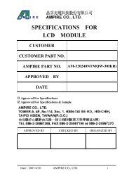
Internet Data SheetHYS64T[32/64]0[0/2]0HM–[3S/3.7/5]–A<strong>Micro</strong>-<strong>DIMM</strong> <strong>DDR2</strong> <strong>SDRAM</strong> <strong>Modules</strong>5 Package OutlinesThis chapter contains the package outlines of the products.FIGURE 5Package Outline Raw Card A L-DIM-<strong>214</strong>-1 Notes1. Drawing according to ISO 80152. Dimensions in mm3. General tolerances +/- 0.15Rev. 1.11, 2006-11 3903062006-HT1R-Z2PY
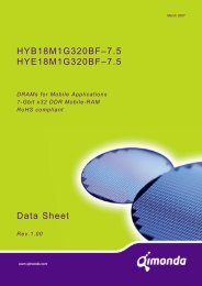
Internet Data SheetHYS64T[32/64]0[0/2]0HM–[3S/3.7/5]–A<strong>Micro</strong>-<strong>DIMM</strong> <strong>DDR2</strong> <strong>SDRAM</strong> <strong>Modules</strong>FIGURE 6Package Outline Raw Card B L-DIM-<strong>214</strong>-2 Notes1. Drawing according to ISO 80152. Dimensions in mm3. General tolerances +/- 0.15Rev. 1.11, 2006-11 4003062006-HT1R-Z2PY
Internet Data Sheet6 Product Type NomenclatureHYS64T[32/64]0[0/2]0HM–[3S/3.7/5]–A<strong>Micro</strong>-<strong>DIMM</strong> <strong>DDR2</strong> <strong>SDRAM</strong> <strong>Modules</strong>Qimonda’s nomenclature uses simple coding combined with some proprietary coding. Table 24 provides examples for moduleand component product type number as well as the field number. The detailed field description together with possible valuesand coding explanation is listed for modules in Table 25 and for components in Table 26.Example forField NumberTABLE 24Nomenclature Fields and Examples1 2 3 4 5 6 7 8 9 10 11<strong>Micro</strong>-<strong>DIMM</strong> HYS 64 T 64/128 0 2 0 K M –5 –A<strong>DDR2</strong> DRAM HYB 18 T 512/1G 16 0 A C –5Field Description Values Coding1 Qimonda Module Prefix HYS Constant2 Module Data Width [bit] 64 Non-ECC72 ECC3 DRAM Technology T <strong>DDR2</strong>4 Memory Density per I/O [Mbit];32 256 MByteModule Density 1) 64 512 MByte128 1 GByte256 2 GByte512 4 GByte5 Raw Card Generation 0 .. 9 Look up table6 Number of Module Ranks 0, 2, 4 1, 2, 47 Product Variations 0 .. 9 Look up table8 Package, Lead-Free Status A .. Z Look up table9 Module Type D SO-<strong>DIMM</strong>M<strong>Micro</strong>-<strong>DIMM</strong>RRegisteredUUnbufferedFFully BufferedTABLE 25<strong>DDR2</strong> <strong>DIMM</strong> NomenclatureRev. 1.11, 2006-11 4103062006-HT1R-Z2PY
Internet Data SheetHYS64T[32/64]0[0/2]0HM–[3S/3.7/5]–A<strong>Micro</strong>-<strong>DIMM</strong> <strong>DDR2</strong> <strong>SDRAM</strong> <strong>Modules</strong>Field Description Values Coding10 Speed Grade –2.5F PC2–6400 5–5–5–2.5 PC2–6400 6–6–6–3 PC2–5300 4–4–4–3S PC2–5300 5–5–5–3.7 PC2–4200 4–4–4–5 PC2–3200 3–3–311 Die Revision –A First–B Second1) Multiplying “Memory Density per I/O” with “Module Data Width” and dividing by 8 for Non-ECC and 9 for ECC modules gives the overallmodule memory density in MBytes as listed in column “Coding”.Field Description Values Coding1 Qimonda Component Prefix HYB Constant2 Interface Voltage [V] 18 SSTL_183 DRAM Technology T <strong>DDR2</strong>4 Component Density [Mbit] 256 256 Mbit512 512 Mbit1G1 Gbit2G2 Gbit5+6 Number of I/Os 40 ×480 ×816 ×167 Product Variations 0 .. 9 Look up table8 Die Revision A FirstBSecond9 Package, Lead-Free Status C FBGA, lead-containingFFBGA, lead-free10 Speed Grade –25F <strong>DDR2</strong>-800 5-5-5–2.5 <strong>DDR2</strong>-800 6-6-6–3 <strong>DDR2</strong>-667 4-4-4–3S <strong>DDR2</strong>-667 5-5-5–3.7 <strong>DDR2</strong>-533 4-4-4–5 <strong>DDR2</strong>-400 3-3-3TABLE 26<strong>DDR2</strong> DRAM NomenclatureRev. 1.11, 2006-11 4203062006-HT1R-Z2PY
Internet Data SheetHYS64T[32/64]0[0/2]0HM–[3S/3.7/5]–A<strong>Micro</strong>-<strong>DIMM</strong> <strong>DDR2</strong> <strong>SDRAM</strong> <strong>Modules</strong>Table of Contents1 Overview . . . . . . . . . . . . . . . . . . . . . . . . . . . . . . . . . . . . . . . . . . . . . . . . . . . . . . . . . . . . . . . . . . . . . . . . . . . . . . . . . 31.1 Features . . . . . . . . . . . . . . . . . . . . . . . . . . . . . . . . . . . . . . . . . . . . . . . . . . . . . . . . . . . . . . . . . . . . . . . . . . . . . . . . . 31.2 Description . . . . . . . . . . . . . . . . . . . . . . . . . . . . . . . . . . . . . . . . . . . . . . . . . . . . . . . . . . . . . . . . . . . . . . . . . . . . . . . . 42 <strong>Pin</strong> Configuration . . . . . . . . . . . . . . . . . . . . . . . . . . . . . . . . . . . . . . . . . . . . . . . . . . . . . . . . . . . . . . . . . . . . . . . . . 62.1 <strong>Pin</strong> Configuration . . . . . . . . . . . . . . . . . . . . . . . . . . . . . . . . . . . . . . . . . . . . . . . . . . . . . . . . . . . . . . . . . . . . . . . . . . . 63 Electrical Characteristics . . . . . . . . . . . . . . . . . . . . . . . . . . . . . . . . . . . . . . . . . . . . . . . . . . . . . . . . . . . . . . . . . . 133.1 Absolute Maximum Ratings . . . . . . . . . . . . . . . . . . . . . . . . . . . . . . . . . . . . . . . . . . . . . . . . . . . . . . . . . . . . . . . . . . 133.2 DC Operating Conditions . . . . . . . . . . . . . . . . . . . . . . . . . . . . . . . . . . . . . . . . . . . . . . . . . . . . . . . . . . . . . . . . . . . . 143.3 Timing Characteristics . . . . . . . . . . . . . . . . . . . . . . . . . . . . . . . . . . . . . . . . . . . . . . . . . . . . . . . . . . . . . . . . . . . . . . 153.3.1 Speed Grade Definitions . . . . . . . . . . . . . . . . . . . . . . . . . . . . . . . . . . . . . . . . . . . . . . . . . . . . . . . . . . . . . . . . . . 153.3.2 Component AC Timing Parameters . . . . . . . . . . . . . . . . . . . . . . . . . . . . . . . . . . . . . . . . . . . . . . . . . . . . . . . . . . 163.3.3 ODT AC Electrical Characteristics . . . . . . . . . . . . . . . . . . . . . . . . . . . . . . . . . . . . . . . . . . . . . . . . . . . . . . . . . . . 263.4 I DD Specifications and Conditions . . . . . . . . . . . . . . . . . . . . . . . . . . . . . . . . . . . . . . . . . . . . . . . . . . . . . . . . . . . . . 284 SPD Codes . . . . . . . . . . . . . . . . . . . . . . . . . . . . . . . . . . . . . . . . . . . . . . . . . . . . . . . . . . . . . . . . . . . . . . . . . . . . . . 335 Package Outlines . . . . . . . . . . . . . . . . . . . . . . . . . . . . . . . . . . . . . . . . . . . . . . . . . . . . . . . . . . . . . . . . . . . . . . . . 396 Product Type Nomenclature . . . . . . . . . . . . . . . . . . . . . . . . . . . . . . . . . . . . . . . . . . . . . . . . . . . . . . . . . . . . . . . . 41Table of Contents . . . . . . . . . . . . . . . . . . . . . . . . . . . . . . . . . . . . . . . . . . . . . . . . . . . . . . . . . . . . . . . . . . . . . . . . 43Rev. 1.11, 2006-11 4303062006-HT1R-Z2PY
Internet Data SheetEdition 2006-11Published by Qimonda AGGustav-Heinemann-Ring 212D-81739 München, Germany© Qimonda AG 2006.All Rights Reserved.Legal DisclaimerThe information given in this Internet Data Sheet shall in no event be regarded as a guarantee of conditions or characteristics(“Beschaffenheitsgarantie”). With respect to any examples or hints given herein, any typical values stated herein and/or anyinformation regarding the application of the device, Qimonda hereby disclaims any and all warranties and liabilities of any kind,including without limitation warranties of non-infringement of intellectual property rights of any third party.InformationFor further information on technology, delivery terms and conditions and prices please contact your nearest Qimonda Office.WarningsDue to technical requirements components may contain dangerous substances. For information on the types in question pleasecontact your nearest Qimonda Office.Qimonda Components may only be used in life-support devices or systems with the express written approval of Qimonda, if afailure of such components can reasonably be expected to cause the failure of that life-support device or system, or to affectthe safety or effectiveness of that device or system. Life support devices or systems are intended to be implanted in the humanbody, or to support and/or maintain and sustain and/or protect human life. If they fail, it is reasonable to assume that the healthof the user or other persons may be endangered.www.qimonda.com
![Internet Data Sheet HYS72T[32/64]xxxHP-[3S/3.7]-A Rev. 1.01 - UBiio](https://img.yumpu.com/50510224/1/184x260/internet-data-sheet-hys72t32-64xxxhp-3s-37-a-rev-101-ubiio.jpg?quality=85)
![Internet Data Sheet HYB18TC256[80/16]0BF Rev. 1.3 - UBiio](https://img.yumpu.com/50510226/1/184x260/internet-data-sheet-hyb18tc25680-160bf-rev-13-ubiio.jpg?quality=85)

![Internet Data Sheet HY[B/I]39SC128[800/160]FE Rev. 1.1 - UBiio](https://img.yumpu.com/31629373/1/184x260/internet-data-sheet-hyb-i39sc128800-160fe-rev-11-ubiio.jpg?quality=85)