Energy Calculation Worksheet
Energy Calculation Worksheet
Energy Calculation Worksheet

Create successful ePaper yourself
Turn your PDF publications into a flip-book with our unique Google optimized e-Paper software.
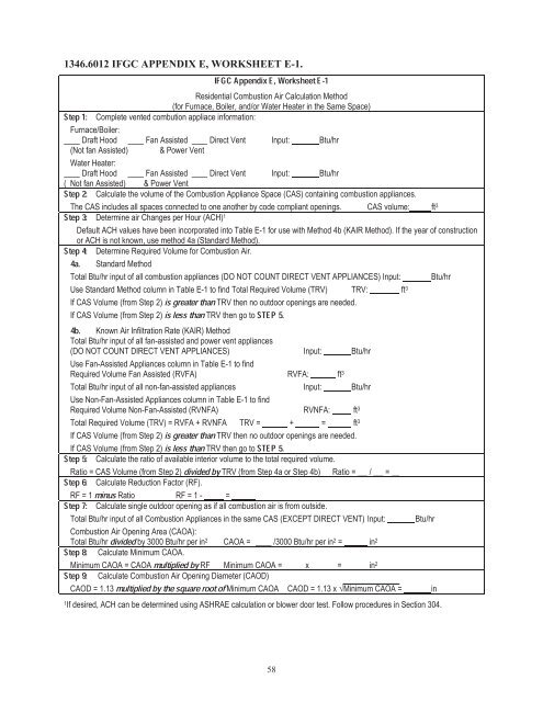
IFGC Appendix E, <strong>Worksheet</strong> E-1Residential Combustion Air <strong>Calculation</strong> Method1346.6012 IFGC APPENDIX E, WORKSHEET E-1.Step 1:(for Furnace, Boiler, and/or Water Heater in the Same Space)Complete vented combution appliace information:Furnace/Boiler:Draft Hood Fan Assisted Direct Vent Input: Btu/hr(Not fan Assisted) & Power VentWater Heater:Step 2:Draft Hood Fan Assisted Direct Vent Input: Btu/hr( Not fan Assisted) & Power VentCalculate the volume of the Combustion Appliance Space (CAS) containing combustion appliances.Step 3:The CAS includes all spaces connected to one another by code compliant openings.Determine air Changes per Hour (ACH) 1CAS volume: ft 3StepDefault ACH values have been incorporated into Table E-1 for use with Method 4b (KAIR Method). If the year of construction4a. 4:or ACH is not known, use method 4a (Standard Method).Determine Required Volume for Combustion Air.Standard MethodTotal Btu/hr input of all combustion appliances (DO NOT COUNT DIRECT VENT APPLIANCES) Input: Btu/hrisUse Standard Method column in Table E-1 to find Total Required Volume (TRV) TRV: ftis less than STEP 5.3If CAS Volume (from Step 2)If4b.CAS Volume (from Step 2) TRV then go toKnown Air Infiltration Rate (KAIR) MethodTotal Btu/hr input of all fan-assisted and power vent appliances(DO NOT COUNT DIRECT VENT APPLIANCES) Input: Btu/hrUse Fan-Assisted Appliances column in Table E-1 to findRequired Volume Fan Assisted (RVFA) RVFA: ft 3Total Btu/hr input of all non-fan-assisted appliances Input: Btu/hrUse Non-Fan-Assisted Appliances column in Table E-1 to findRequired Volume Non-Fan-Assisted (RVNFA) RVNFA: ftis 3Total Required Volume (TRV) = RVFA + RVNFA TRV = + = ftis less than STEP 5.3If CAS Volume (from Step 2)If CAS Volume (from Step 2) TRV then go toStep 5:Step 6: dividedCalculateRatio = CAS Volume (from Step 2)Step 7: minusCalculateRF = 1Calculategreater than TRV then no outdoor openings are needed.greater than TRV then no outdoor openings are needed.bythe ratio of available interior volume to the total required volume.TRV (from Step 4a or Step 4b) Ratio = / =Reduction Factor (RF).Ratio RF = 1 - =single outdoor opening as if all combustion air is from outside.Total Btu/hr input of all Combustion Appliances in the same CAS (EXCEPT DIRECT VENT) Input:StepCombustion8: dividedAir Opening Area (CAOA):Total Btu/hr by 3000 Btu/hr per in 2 CAOA = /3000 Btu/hr per in 2 = in 2Step 9: multiplied byCalculate Minimum CAOA.Minimum CAOAmultiplied= CAOA RF Minimum CAOA = x = in 2Calculate Combustion Air Opening Diameter (CAOD)CAOD = 1.13Btu/hrby the square root of Minimum CAOA CAOD = 1.13 x Minimum CAOA = in1 If desired, ACH can be determined using ASHRAE calculation or blower door test. Follow procedures in Section 304.58
1346.6014 IFGC APPENDIX E, TABLEIFGC AppendixE-1.E, Table E-1Residential Combustion Air Required Volume (Required Interior Volume Based on Input Rating of Appliances)Known Air Infiltration Rate (KAIR) Method (ft 3 )Input Rating Standard Method Fan Assisted Non-Fan-Assisted(Btu/hr) (ft 3 ) 1994 1 to Present Pre 1994 2 1994 1 to Present Pre 1994 25,000 250 375 188 525 26310,000 500 750 375 1,050 52515,000 750 1,125 563 1,575 78820,000 1,000 1,500 750 2,100 1,05025,000 1,250 1,875 938 2,625 1,31330,000 1,500 2,250 1,125 3,150 1,57535,000 1,750 2,625 1,313 3,675 1,83840,000 2,000 3,000 1,500 4,200 2,10045,000 2,250 3,375 1,688 4,725 2,36350,000 2,500 3,750 1,875 5,250 2,62555,000 2,750 4,125 2,063 5,775 2,88860,000 3,000 4,500 2,250 6,300 3,15065,000 3,250 4,875 2,438 6,825 3,41370,000 3,500 5,250 2,625 7,350 3,67575,000 3,750 5,625 2,813 7,875 3,93880,000 4,000 6,000 3,000 8,400 4,20085,000 4,250 6,375 3,188 8,925 4,46390,000 4,500 6,750 3,375 9,450 4,72595,000 4,750 7,125 3,563 9,975 4,988100,000 5,000 7,500 3,750 10,500 5,250105,000 5,250 7,875 3,938 11,025 5,513110,000 5,500 8,250 4,125 11,550 5,775115,000 5,750 8,625 4,313 12,075 6,038120,000 6,000 9,000 4,500 12,600 6,300125,000 6,250 9,375 4,688 13,125 6,563130,000 6,500 9,750 4,875 13,650 6,825135,000 6,750 10,125 5,063 14,175 7,088140,000 7,000 10,500 5,250 14,700 7,350145,000 7,250 10,875 5,438 15,225 7,613150,000 7,500 11,250 5,625 15,750 7,875155,000 7,750 11,625 5,813 16,275 8,138160,000 8,000 12,000 6,000 16,800 8,400165,000 8,250 12,375 6,188 17,325 8,663170,000 8,500 12,750 6,375 17,850 8,925175,000 8,750 13,125 6,563 18,375 9,188180,000 9,000 13,500 6,750 18,900 9,450185,000 9,250 13,875 6,938 19,425 9,713190,000 9,500 14,250 7,125 19,950 9,975195,000 9,750 14,625 7,313 20,475 10,238200,000 10,000 15,000 7,500 21,000 10,500205,000 10,250 15,375 7,688 21,525 10,763210,000 10,500 15,750 7,875 22,050 11,025215,000 10,750 16,125 8,063 22,575 11,288220,000 11,000 16,500 8,250 23,100 11,550225,000 11,250 16,857 8,438 23,625 11,813230,000 11,500 17,250 8,625 24,150 12,0751The 1994 date refers to dwellings constructed under the 1994 Minnesota <strong>Energy</strong> Code. The default KAIR used in this section of the table is 0.20 ACH.2This section of the table is to be used for dwellings constructed prior to 1994. The default KAIR used in this section of the table is 0.40 ACH.59
Table 501.3.1Procedure to Determine Makeup Air Quantity for Exhaust Equipment in DwellingsUse the Appropriate Column to Estimate House InfiltrationOne or multiple fanassistedappliances andpower vent or direct ventappliances BOne or multiple power ventor direct vent appliances orno combustion appliances AOne atmosphericallyvented gas or oilappliance or one solidfuel appliance CMultiple atmosphericallyvented gas or oilappliances or solid fuelappliances D1a) pressure factor (cfm/sf) 0.15 0.09 0.06 0.03b) conditioned floor area(sf) (includingunfinished basements)Estimated HouseInfiltration (cfm):[1a x 1b]2. Exhaust Capacitya) continuous exhaustonlyventilation systems(cfm): (not applicableto balanced ventilationsystems such as HRV)b) clothes dryer 135 135 135 135c) 80% of largest exhaustrating (cfm): (notapplicable ifrecirculating system orif powered makeup airis electricallyinterlocked andmatched to exhaust)d) 80% of next largestexhaust rating (cfm):(not applicable ifrecirculating system orif powered makeup airis electricallyinterlocked andmatched to exhaust)Total Exhaust Capacity(cfm): [2a+2b+2c+2d]3. Makeup AirRequirementa) Total Exhaust Capacity(from above)b) Estimated HouseInfiltration (from above)Makeup Air Quantity(cfm): [3a – 3b](if value is negative, nomakeup air is needed)4. For Makeup AirOpening Sizing, refer toTable 501.3.2ABCDnot applicableUse this column if there are other than fan-assisted or atmospherically vented gas or oil appliances or if there are no combustionappliances.Use this column if there is one fan-assisted appliance per venting system. Other than atmospherically vented appliances may also beincluded.Use this column if there is one atmospherically vented (other than fan-assisted) gas or oil appliance per venting system or one solid fuelappliance.Use this column if there are multiple atmospherically vented gas or oil appliances using a common vent or if there are atmosphericallyvented gas or oil appliances and solid fuel appliances.13