Using the Stellaris Microcontroller Analog-to-Digital Converter - Chess
Using the Stellaris Microcontroller Analog-to-Digital Converter - Chess
Using the Stellaris Microcontroller Analog-to-Digital Converter - Chess

You also want an ePaper? Increase the reach of your titles
YUMPU automatically turns print PDFs into web optimized ePapers that Google loves.
<strong>Using</strong> <strong>the</strong> <strong>Stellaris</strong>® <strong>Microcontroller</strong><strong>Analog</strong>-<strong>to</strong>-<strong>Digital</strong> <strong>Converter</strong> (ADC)APPLICATION NOTEAN01247-02Copyright © 2007-2008 Luminary Micro, Inc.
Application Note<strong>Using</strong> <strong>the</strong> <strong>Stellaris</strong>® <strong>Microcontroller</strong> <strong>Analog</strong>-<strong>to</strong>-<strong>Digital</strong> <strong>Converter</strong> (ADC)Legal Disclaimers and Trademark InformationINFORMATION IN THIS DOCUMENT IS PROVIDED IN CONNECTION WITH LUMINARY MICRO PRODUCTS. NO LICENSE,EXPRESS OR IMPLIED, BY ESTOPPEL OR OTHERWISE, TO ANY INTELLECTUAL PROPERTY RIGHTS IS GRANTED BY THISDOCUMENT. EXCEPT AS PROVIDED IN LUMINARY MICRO’S TERMS AND CONDITIONS OF SALE FOR SUCH PRODUCTS,LUMINARY MICRO ASSUMES NO LIABILITY WHATSOEVER, AND LUMINARY MICRO DISCLAIMS ANY EXPRESS OR IMPLIEDWARRANTY, RELATING TO SALE AND/OR USE OF LUMINARY MICRO’S PRODUCTS INCLUDING LIABILITY OR WARRANTIESRELATING TO FITNESS FOR A PARTICULAR PURPOSE, MERCHANTABILITY, OR INFRINGEMENT OF ANY PATENT, COPYRIGHTOR OTHER INTELLECTUAL PROPERTY RIGHT. LUMINARY MICRO’S PRODUCTS ARE NOT INTENDED FOR USE IN MEDICAL,LIFE SAVING, OR LIFE-SUSTAINING APPLICATIONS.Luminary Micro may make changes <strong>to</strong> specifications and product descriptions at any time, without notice. Contact your local Luminary Microsales office or your distribu<strong>to</strong>r <strong>to</strong> obtain <strong>the</strong> latest specifications before placing your product order.Designers must not rely on <strong>the</strong> absence or characteristics of any features or instructions marked "reserved" or "undefined." Luminary Microreserves <strong>the</strong>se for future definition and shall have no responsibility whatsoever for conflicts or incompatibilities arising from future changes <strong>to</strong><strong>the</strong>m.Copyright © 2007–2008 Luminary Micro, Inc. All rights reserved. <strong>Stellaris</strong>, Luminary Micro, and <strong>the</strong> Luminary Micro logo are registeredtrademarks of Luminary Micro, Inc. or its subsidiaries in <strong>the</strong> United States and o<strong>the</strong>r countries. ARM and Thumb are registered trademarks, andCortex is a trademark of ARM Limited. O<strong>the</strong>r names and brands may be claimed as <strong>the</strong> property of o<strong>the</strong>rs.Luminary Micro, Inc.108 Wild Basin, Suite 350Austin, TX 78746Main: +1-512-279-8800Fax: +1-512-279-8879http://www.luminarymicro.comOc<strong>to</strong>ber 28, 2008 2
Application Note<strong>Using</strong> <strong>the</strong> <strong>Stellaris</strong>® <strong>Microcontroller</strong> <strong>Analog</strong>-<strong>to</strong>-<strong>Digital</strong> <strong>Converter</strong> (ADC)Table of ContentsIntroduction ......................................................................................................................................................... 4Sample Sequencers ........................................................................................................................................... 4Module Configuration Example........................................................................................................................... 5Module Initialization ........................................................................................................................................ 6Sample Sequence Configuration .................................................................................................................... 7<strong>Using</strong> ADC Interrupts .................................................................................................................................... 10Data Retrieval ............................................................................................................................................... 10Differential Sampling......................................................................................................................................... 11Hardware Averaging Circuit.............................................................................................................................. 15Conclusion ........................................................................................................................................................ 16References ....................................................................................................................................................... 16Oc<strong>to</strong>ber 28, 2008 3
Application Note<strong>Using</strong> <strong>the</strong> <strong>Stellaris</strong>® <strong>Microcontroller</strong> <strong>Analog</strong>-<strong>to</strong>-<strong>Digital</strong> <strong>Converter</strong> (ADC)IntroductionLuminary Micro <strong>Stellaris</strong>® microcontrollers that are equipped with an analog-<strong>to</strong>-digital converter(ADC), use an innovative sequence-based sampling architecture designed <strong>to</strong> be extremely flexible,yet easy <strong>to</strong> use. This application note describes <strong>the</strong> sampling architecture of <strong>the</strong> ADC. Sinceprogrammers can configure <strong>Stellaris</strong> microcontrollers ei<strong>the</strong>r through <strong>the</strong> powerful <strong>Stellaris</strong> FamilyDriver Library or through direct writes <strong>to</strong> <strong>the</strong> device's control registers, this application note describesboth methods. The information presented in this document is intended <strong>to</strong> complement <strong>the</strong> ADCchapter of <strong>the</strong> device datasheet, and assumes <strong>the</strong> reader has a basic understanding of how ADCsfunction.Sample SequencersMost analog-<strong>to</strong>-digital converter implementations in 8-,16-, and 32-bit microcontrollers requireprocessor intervention <strong>to</strong> configure each conversion when <strong>the</strong> analog input/channel is changed.Luminary Micro's sequence-based architecture gives software <strong>the</strong> ability <strong>to</strong> enable up <strong>to</strong> fourseparate sample sequences (encompassing all of <strong>the</strong> analog input channels) with a single series ofconfiguration writes.The ADC module has a <strong>to</strong>tal of four sample sequencers that allow sampling of 1, 4 (<strong>the</strong>re are two4-beat sequencers), or 8 analog sources with a single-trigger event (see Figure 1). Each samplesequencer has its own set of configuration registers making it completely independent from <strong>the</strong> o<strong>the</strong>rsequencers. All steps in a sample sequence are configurable, allowing software <strong>to</strong> select <strong>the</strong> analoginput channel (including <strong>the</strong> temperature sensor), single-ended or differential mode sampling, andwhe<strong>the</strong>r or not <strong>to</strong> generate an interrupt after <strong>the</strong> step completes. The sample sequences also haveconfigurable priority <strong>to</strong> handle cases where multiple sequences are triggered by <strong>the</strong> same triggersource or trigger simultaneously.Figure 1. Sample Sequencer StructureSample Sequencer 0 Sample Sequencer 1 Sample Sequencer 2 Sample Sequencer 3Step 0Step 0Step 0Step 0Step 1Step 1Step 1Step 2Step 2Step 2Step 3Step 3Step 3Step 4Step 5Each step can configure:Step 6Step 7- <strong>Analog</strong> source (pin or temperature sensor)- Interrupt generation- Single-ended or differential sampling- End of sequenceA sample sequence can be triggered by various sources, including <strong>the</strong> processor, timers, analogcompara<strong>to</strong>rs, PWM unit or GPIO. For situations where multiple sequences have <strong>the</strong> same triggersource or are triggered simultaneously, <strong>the</strong> ADC arbitrates execution order based on <strong>the</strong> configuredsequence priorities. When a sample sequence is triggered, it begins sampling at <strong>the</strong> programmedOc<strong>to</strong>ber 28, 2008 4
Application Note<strong>Using</strong> <strong>the</strong> <strong>Stellaris</strong>® <strong>Microcontroller</strong> <strong>Analog</strong>-<strong>to</strong>-<strong>Digital</strong> <strong>Converter</strong> (ADC)sampling rate (250K, 500K, or 1M samples/second, depending on <strong>the</strong> device), iterating through <strong>the</strong>steps of <strong>the</strong> sequence. Sampling continues until a step has its END bit set, indicating <strong>the</strong> end of <strong>the</strong>sequence. The END bit can be set for any step in <strong>the</strong> sequence, meaning a given sample sequenceis not required <strong>to</strong> collect its maximum number of samples. When <strong>the</strong> sample sequence completes,<strong>the</strong> conversion results are s<strong>to</strong>red in <strong>the</strong> sample sequence FIFO, and can be retrieved by <strong>the</strong>processor.Module Configuration ExampleTo demonstrate <strong>the</strong> steps required <strong>to</strong> configure <strong>the</strong> ADC, consider <strong>the</strong> example shown in Figure 2.There are a <strong>to</strong>tal of three sensors being moni<strong>to</strong>red, in addition <strong>to</strong> <strong>the</strong> on-chip temperature sensor.Since three analog inputs are used, this example assumes <strong>the</strong> specific <strong>Stellaris</strong> device has at leastthree analog inputs. Each sample sequence has its own FIFO with <strong>the</strong> number of slots equivalent <strong>to</strong><strong>the</strong> size of <strong>the</strong> sequencer.Figure 2. Example System Configuration<strong>Stellaris</strong> <strong>Microcontroller</strong>TimertriggerSample Sequencer 1AN0Sensor 1Step 0Step 1AN1Sensor 2Step 2Step 3 - UnusedAN2Sensor 3ProcessortriggerSample Sequencer 3Step 0TemperatureSensorNotice how <strong>the</strong> analog inputs are mapped <strong>to</strong> <strong>the</strong> individual steps in <strong>the</strong> sample sequencer. Since<strong>the</strong>re are three sensor inputs <strong>to</strong> moni<strong>to</strong>r, one of <strong>the</strong> four step sequencers (in this case, samplesequence 1) is used. The temperature sensor is sampled using sample sequence 3 since it requiresonly one step and has a separate trigger source. If <strong>the</strong> temperature sensor was configured <strong>to</strong> have atimer trigger, it could be placed in <strong>the</strong> unused step of sequence 1.Note: All code examples in <strong>the</strong> following sections show both direct register writes/reads and APIcalls <strong>to</strong> <strong>the</strong> <strong>Stellaris</strong>® Peripheral Driver Library. If attempting <strong>to</strong> reproduce <strong>the</strong> direct registeraccess examples, <strong>the</strong> appropriate IC header file, for example “lm3s811.h” for an LM3S811part, must be included. These header files, one for each member of <strong>the</strong> <strong>Stellaris</strong> family, canbe found in <strong>the</strong> <strong>Stellaris</strong>Ware/inc direc<strong>to</strong>ry in <strong>the</strong> installed software tree. To make use of <strong>the</strong><strong>Stellaris</strong> Peripheral Driver Library instead of direct register access, header files hw_types.h,hw_memmap.h, and adc.h are required. These can be found in <strong>the</strong> <strong>Stellaris</strong>Ware and<strong>Stellaris</strong>Ware/DriverLib direc<strong>to</strong>ries.Oc<strong>to</strong>ber 28, 2008 5
Application Note<strong>Using</strong> <strong>the</strong> <strong>Stellaris</strong>® <strong>Microcontroller</strong> <strong>Analog</strong>-<strong>to</strong>-<strong>Digital</strong> <strong>Converter</strong> (ADC)Table 3.Valid ADC Sample RatesValue Sample Rate Value Sample Rate0x0 125K samples/second 0x2 500K samples/second0x1 250K samples/second 0x3 1M samples/secondSample Sequence ConfigurationBefore changing configuration parameters in <strong>the</strong> ADC, it is a good practice <strong>to</strong> disable <strong>the</strong> targetedsample sequence. Disabling a sample sequence allows for safe modification of <strong>the</strong> configurationparameters without inadvertent triggers. To disable one or more sequences, set <strong>the</strong> correspondingbits in <strong>the</strong> ADC Active Sample Sequencer (ADCACTSS) register <strong>to</strong> '0'. For this example, sequences 1and 3 should be disabled.Table 4.Disabling <strong>the</strong> Sample Sequences<strong>Using</strong> Direct Register Write//// Disable sample sequences 1 and 3//// ADC Active Sample Sequencer register//ADC_ACTSS_R &= ~(ADC_ACTSS_ASEN1 | ADC_ACTSS_ASEN3);//// Disable sample sequences 1 and 3//ADCSequenceDisable(ADC_BASE, 1);ADCSequenceDisable(ADC_BASE, 3);<strong>Using</strong> DriverLibWith <strong>the</strong> sequences disabled, it is now safe <strong>to</strong> load <strong>the</strong> new configuration parameters. Configure <strong>the</strong>priority of <strong>the</strong> sample sequences first. In a situation where multiple ADC triggers are activesimultaneously, or multiple sequences are triggered by <strong>the</strong> same source, <strong>the</strong> ADC control logic has<strong>to</strong> decide which sample sequence runs first. Out of reset, <strong>the</strong> sample sequences are prioritizedbased on <strong>the</strong>ir number, meaning sequence 0 has <strong>the</strong> highest priority and sequence 3 has <strong>the</strong> lowestpriority (<strong>the</strong> register bit fields range from 0-3, with 0 being <strong>the</strong> highest priority and 3 being <strong>the</strong> lowest).This example does not have a particular priority requirement, so sequence 3 is configured <strong>to</strong> have<strong>the</strong> highest priority.In addition <strong>to</strong> <strong>the</strong> priority, <strong>the</strong> ADC trigger sources must be configured. The ADC offers a wide varietyof trigger sources including <strong>the</strong> processor, analog compara<strong>to</strong>rs (if available), GPIO, PWM, andtimers, but this example requires sequence 1 <strong>to</strong> have a timer trigger, and sequence 3 <strong>to</strong> have aprocessor trigger.Oc<strong>to</strong>ber 28, 2008 7
Application Note<strong>Using</strong> <strong>the</strong> <strong>Stellaris</strong>® <strong>Microcontroller</strong> <strong>Analog</strong>-<strong>to</strong>-<strong>Digital</strong> <strong>Converter</strong> (ADC)Table 5.Configuring <strong>the</strong> Sequence Priority and Trigger<strong>Using</strong> Direct Register Write//// Configure sequence priority: order (highest <strong>to</strong> lowest)= 3, 1, 0, 2//// ADC Sample Sequencer Priority register//ADC_SSPRI_R = (ADC_SSPRI_SS3_1ST | ADC_SSPRI_SS1_2ND |ADC_SSPRI_SS0_3RD | ADC_SSPRI_SS2_4TH);//// Set up sequence triggers: sequence 1 = timer (encoding 0x5),// sequence 3 = Processor (encoding 0x0)//// ADC Event Multiplexer Select register//ADC_EMUX_R = (ADC_EMUX_EM1_TIMER | ADC_EMUX_EM3_PROCESSOR);<strong>Using</strong> DriverLib//// Configure sample sequence 1: timer trigger, priority = 1//ADCSequenceConfigure(ADC_BASE, 1, ADC_TRIGGER_TIMER, 1);//// Configure sample sequence 3: processor trigger, priority = 0//ADCSequenceConfigure(ADC_BASE, 3, ADC_TRIGGER_PROCESSOR, 0);The next step in <strong>the</strong> configuration process is setting up <strong>the</strong> sequence steps. There are two registersthat are responsible for <strong>the</strong> individual steps of <strong>the</strong> sample sequence: <strong>the</strong> ADC Sample Sequence InputMultiplexer Select (ADCSSMUX) and ADC Sample Sequence Control (ADCSSCTL) registers.The ADCSSMUX register allows software <strong>to</strong> select <strong>the</strong> analog input source for each step in <strong>the</strong>sequence, and a step can select any one of <strong>the</strong> analog inputs. If a sequence step is sampling <strong>the</strong>internal temperature sensor, <strong>the</strong> corresponding value in <strong>the</strong> ADCSSMUX register is ignored by <strong>the</strong>hardware.Control information such as sampling mode (single-ended or differential), temperature sensorsampling, interrupts, and end-of-sequence is s<strong>to</strong>red in <strong>the</strong> ADCSSCTL register. Each step in asample sequence has its own 4-bit nibble, allowing software <strong>to</strong> set any of <strong>the</strong> aforementionedconfiguration options. The first step in <strong>the</strong> sequence occupies <strong>the</strong> least significant nibble in <strong>the</strong>register, and so on. It is software's responsibility <strong>to</strong> set <strong>the</strong> END bit for <strong>the</strong> last step of a sequence. If<strong>the</strong> END bit is not set for a sequence, unpredictable behavior can occur.Figure 3 shows <strong>the</strong> layout of <strong>the</strong> configuration nibble. The “n” next <strong>to</strong> each field is associated with <strong>the</strong>step number; for step 3, n is 3.Oc<strong>to</strong>ber 28, 2008 8
Application Note<strong>Using</strong> <strong>the</strong> <strong>Stellaris</strong>® <strong>Microcontroller</strong> <strong>Analog</strong>-<strong>to</strong>-<strong>Digital</strong> <strong>Converter</strong> (ADC)Figure 3. Sequence Step Configuration NibbleTSn IEn ENDn DnTemperature SensorInterrupt Enable End of Sequence Differential SamplingTable 6.Configuring <strong>the</strong> Sequence Steps<strong>Using</strong> Direct Register Write//// Configure sample sequence 1 input multiplexer://// - Step 0: <strong>Analog</strong> Input 0// - Step 1: <strong>Analog</strong> Input 1// - Step 2: <strong>Analog</strong> Input 2//// ADC Sample Sequence Input Multiplexer Select 1 register//ADC_SSMUX1_R = ((0
Application Note<strong>Using</strong> <strong>the</strong> <strong>Stellaris</strong>® <strong>Microcontroller</strong> <strong>Analog</strong>-<strong>to</strong>-<strong>Digital</strong> <strong>Converter</strong> (ADC)<strong>Using</strong> DriverLib//// Configure sample sequence 3 steps 0, 1 and 2//ADCSequenceStepConfigure(ADC_BASE, 1, 0, ADC_CTL_CH0);ADCSequenceStepConfigure(ADC_BASE, 1, 1, ADC_CTL_CH1);ADCSequenceStepConfigure(ADC_BASE, 1, 2, ADC_CTL_CH2 | ADC_CTL_IE | ADC_CTL_END)//// Configure sample sequence 3 step 0//ADCSequenceStepConfigure(ADC_BASE, 3, 0, ADC_CTL_TS | ADC_CTL_END);<strong>Using</strong> ADC InterruptsLuminary Micro's sequence-based architecture offers a vast amount of interrupt programmingflexibility. All steps of a sample sequence have <strong>the</strong> capability <strong>to</strong> trigger an interrupt, allowing software<strong>to</strong> set indica<strong>to</strong>rs at any point in a sample sequence.To enable interrupts, software must set <strong>the</strong> MASK bit for <strong>the</strong> sample sequence that requires <strong>the</strong>interrupt. For example, if sample sequence 1 is configured <strong>to</strong> trigger an interrupt, <strong>the</strong> MASK1 bit of <strong>the</strong>ADC Interrupt Mask (ADCIM) register is set <strong>to</strong> '1'.Table 7.Enabling <strong>the</strong> Sample Sequencer Interrupts<strong>Using</strong> Direct Register Write//// Enable <strong>the</strong> interrupt for sample sequence 1//// ADC Interrupt Mask register//ADC_IM_R = ADC_IM_MASK1;<strong>Using</strong> DriverLib//// Enable <strong>the</strong> interrupt for sample sequence 1//ADCIntEnable(ADC_BASE, 1);Even with <strong>the</strong> interrupt mask bit set, software must set <strong>the</strong> step interrupt enable bit (IE) for one ormore steps of a sample sequence for an interrupt <strong>to</strong> occur. The step interrupt enable bit is part of astep's configuration nibble in <strong>the</strong> ADCSSCTL register. In <strong>the</strong> example configuration being discussed,<strong>the</strong> IE bit for step 2 is set (see Table 6, "Configuring <strong>the</strong> Sequence Steps" on page 9).Data RetrievalEach sample sequence has its own FIFO with a depth equal <strong>to</strong> <strong>the</strong> number of steps <strong>the</strong> particularsequence supports (that is, sample sequence 0 has an 8-entry FIFO since it has 8 steps). Dataretrieval from <strong>the</strong> FIFO is very straightforward; reading <strong>the</strong> ADC Sample Sequence FIFO n(ADCSSFIFOn) register returns a value from <strong>the</strong> FIFO.Oc<strong>to</strong>ber 28, 2008 10
Application Note<strong>Using</strong> <strong>the</strong> <strong>Stellaris</strong>® <strong>Microcontroller</strong> <strong>Analog</strong>-<strong>to</strong>-<strong>Digital</strong> <strong>Converter</strong> (ADC)The data returned during a FIFO read is a 32-bit value with <strong>the</strong> conversion result s<strong>to</strong>red in <strong>the</strong> lower10 bits. There are FIFO overflow and underflow flags available in <strong>the</strong> ADC Overflow Status(ADCOSTAT) and ADC Underflow Status (ADCUSTAT) registers, as well as FIFO empty, full, head, andtail pointer information in <strong>the</strong> ADC Sample Sequence FIFO registers.Table 8.Retrieving Data from <strong>the</strong> FIFO<strong>Using</strong> Direct Register Read//// Retrieve data from sample sequence 1 FIFO//// ADC Sample Sequence 1 FIFO register//ulSensor0Data = ADC_SSFIFO1_R;ulSensor1Data = ADC_SSFIFO1_R;ulSensor2Data = ADC_SSFIFO1_R;//// Retrieve data from sample sequence 3 FIFO//// ADC Sample Sequence 3 FIFO register//ulTempSensorData = ADC_SSFIFO3_R;<strong>Using</strong> DriverLib//// Retrieve data from sample sequence 1 FIFO//ADCSequenceDataGet(ADC_BASE, 1, &ulSeq1DataBuffer);//// Retrieve data from sample sequence 3 FIFO//ADCSequenceDataGet(ADC_BASE, 3, &ulSeq3DataBuffer);Differential SamplingIn addition <strong>to</strong> traditional single-ended sampling, <strong>the</strong> ADC module supports differential sampling oftwo analog input channels. To enable differential sampling, software must set <strong>the</strong> D bit in a step'sconfiguration nibble (see Figure 3 on page 9).When a sequence step is configured for differential sampling, its corresponding value in <strong>the</strong>ADCSSMUX register must be set <strong>to</strong> one of <strong>the</strong> four differential pairs, numbered 0-3. Differential pair 0samples analog inputs 0 and 1; differential pair 1 samples analog inputs 2 and 3; and so on (seeTable 9). The ADC does not support o<strong>the</strong>r differential pairings such as analog input 0 with analoginput 3. The number of differential pairs supported is dependent on <strong>the</strong> number of analog inputs on<strong>the</strong> particular <strong>Stellaris</strong> microcontroller device.Oc<strong>to</strong>ber 28, 2008 11
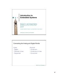
Application Note<strong>Using</strong> <strong>the</strong> <strong>Stellaris</strong>® <strong>Microcontroller</strong> <strong>Analog</strong>-<strong>to</strong>-<strong>Digital</strong> <strong>Converter</strong> (ADC)Table 9.Differential Sampling PairsDifferential Pair<strong>Analog</strong> Inputs0 0 and 11 2 and 32 4 and 53 6 and 7The voltage sampled in differential mode is <strong>the</strong> difference between <strong>the</strong> odd and even channels:ΔV (differential voltage) = V 0 (even channels) – V 1 (odd channels), <strong>the</strong>refore,If ΔV = 0, <strong>the</strong>n <strong>the</strong> conversion result = 0x1FFIf ΔV > 0, <strong>the</strong>n <strong>the</strong> conversion result > 0x1FF (range is 0x1FF–0x3FF)If ΔV < 0, <strong>the</strong>n <strong>the</strong> conversion result < 0x1FF (range is 0–0x1FF)The differential pairs assign polarities <strong>to</strong> <strong>the</strong> analog inputs: <strong>the</strong> even-numbered input is alwayspositive, and <strong>the</strong> odd-numbered input is always negative. In order for a valid conversion result <strong>to</strong>appear, <strong>the</strong> negative input must be in <strong>the</strong> range of ± 1.5 V of <strong>the</strong> positive input. If an analog input isgreater than 3 V or less than 0 V (<strong>the</strong> valid range for analog inputs), <strong>the</strong> input voltage is clipped,meaning it appears as ei<strong>the</strong>r 3 V or 0 V, respectively, <strong>to</strong> <strong>the</strong> ADC.Figure 4 shows an example of <strong>the</strong> negative input centered at 1.5 V. In this configuration, <strong>the</strong>differential range spans from -1.5 V <strong>to</strong> 1.5 V. Figure 5 shows an example where <strong>the</strong> negative input iscentered at -0.75 V meaning inputs on <strong>the</strong> positive input saturate past a differential voltage of -0.75 Vsince <strong>the</strong> input voltage is less than 0 V. Figure 6 shows an example of <strong>the</strong> negative input centered at2.25 V, where inputs on <strong>the</strong> positive channel saturate past a differential voltage of 0.75 V since <strong>the</strong>input voltage would be greater than 3 V.Oc<strong>to</strong>ber 28, 2008 12
Application Note<strong>Using</strong> <strong>the</strong> <strong>Stellaris</strong>® <strong>Microcontroller</strong> <strong>Analog</strong>-<strong>to</strong>-<strong>Digital</strong> <strong>Converter</strong> (ADC)Figure 4. Differential Sampling Range, V in (-) = 1.5 VADC Conversion Result0x3FF0x1FF-1.5VDifferential Voltage,V in (+) = 1.5V- Input Saturation+1.5VFigure 5. Differential Sampling Range, V in (-) = 0.75 VADC Conversion Result0x3FF0x1FF0x0FF-1.5V-0.75VDifferential Voltage,V in (+) = 0.75V+1.5V- Input SaturationOc<strong>to</strong>ber 28, 2008 13
Application Note<strong>Using</strong> <strong>the</strong> <strong>Stellaris</strong>® <strong>Microcontroller</strong> <strong>Analog</strong>-<strong>to</strong>-<strong>Digital</strong> <strong>Converter</strong> (ADC)Figure 6. Differential Sampling Range, V in (-) = 2.25 VADC Conversion Result0x3FF0x2FF0x1FF-1.5VDifferential Voltage,V in (+) = 2.25V+0.75V+1.5V- Input SaturationTable 10. Enabling Differential Sampling<strong>Using</strong> Direct Register Write//// Configure sequence 3, step 0 for differential sampling//// ADC Sample Sequence Control 3 register//ADC_SSCTL3_R = (ADC_SSCTL3_D0 | ADC_SSCTL3_END0);//// Configure sample sequencer 3 input multiplexer <strong>to</strong> sample differential// pair 1//// ADC Sample Sequence Input Multiplexer Select 3 register//ADC_SSMUX3_R = (1
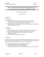
Application Note<strong>Using</strong> <strong>the</strong> <strong>Stellaris</strong>® <strong>Microcontroller</strong> <strong>Analog</strong>-<strong>to</strong>-<strong>Digital</strong> <strong>Converter</strong> (ADC)Hardware Averaging CircuitSome applications require accuracy that exceeds <strong>the</strong> standard specifications of <strong>the</strong> ADC. To addressthis need, <strong>the</strong> ADC module contains a built-in hardware averaging circuit that can oversample <strong>the</strong>input source by up <strong>to</strong> 64 times.When <strong>the</strong> hardware averaging circuit is enabled, all raw data collected by <strong>the</strong> ADC is oversampledby <strong>the</strong> same amount; <strong>the</strong> averager cannot be enabled/disabled on a step-by-step basis in a samplesequence. See Figure 7 for signal path details.Figure 7. Hardware Averaging CircuitResult <strong>to</strong>FIFOHardwareAverager10-bit SAR ADC<strong>Analog</strong>Inputs<strong>Analog</strong> InputSelectThere is also a bandwidth impact that must be considered before using <strong>the</strong> hardware averager.Whatever oversampling fac<strong>to</strong>r is selected for <strong>the</strong> averaging circuit also reduces <strong>the</strong> overall ADCthroughput by <strong>the</strong> same amount. For example, oversampling by 8 reduces <strong>the</strong> throughput of a 500Ksamples/second ADC module <strong>to</strong> 62.5K sample/second since <strong>the</strong> ADC collects and averages 8samples before returning a single conversion result <strong>to</strong> <strong>the</strong> FIFO.To enable <strong>the</strong> hardware averaging circuit, software writes a value between 1 and 6 <strong>to</strong> <strong>the</strong> AVG field of<strong>the</strong> ADC Sample Averaging Control (ADCSAC) register. The amount of oversampling applied <strong>to</strong> <strong>the</strong>input is equivalent <strong>to</strong> 2 AVG . When <strong>the</strong> AVG bit is 0 (<strong>the</strong> default configuration), no averaging is applied<strong>to</strong> <strong>the</strong> input.Table 11.Enabling 8x Hardware Averaging//// Enable 8x hardware averaging//// ADC Sample Averaging Control register//ADC_SAC_R = ADC_SAC_AVG_8X;<strong>Using</strong> Direct Register Write<strong>Using</strong> DriverLib//// Enable 8x hardware averaging//ADCHardwareOversampleConfigure(ADC_BASE, 8);Oc<strong>to</strong>ber 28, 2008 15
Application Note<strong>Using</strong> <strong>the</strong> <strong>Stellaris</strong>® <strong>Microcontroller</strong> <strong>Analog</strong>-<strong>to</strong>-<strong>Digital</strong> <strong>Converter</strong> (ADC)ConclusionWhile architecturally different than many competitive ADC modules, <strong>the</strong> Luminary Micro ADC offersusers more flexibility, control, and features without added processor overhead. Combining astraightforward programming interface and included Driver Library, many users will find <strong>the</strong> LuminaryMicro ADC easy <strong>to</strong> integrate in<strong>to</strong> <strong>the</strong>ir designs.ReferencesThe following are available for download at www.luminarymicro.com:• <strong>Stellaris</strong>® microcontroller data sheet, Publication Number DS-LM3Snnn (where nnn is <strong>the</strong> partnumber for that specific <strong>Stellaris</strong> family device)• <strong>Stellaris</strong>® Peripheral Driver Library User's Guide, Publication Number SW-DRL-UG• <strong>Stellaris</strong>® Peripheral Driver Library, Order Number SW-DRL4Support InformationFor support on Luminary Micro products, contact:support@luminarymicro.com+1-512-279-8800, ext. 3Oc<strong>to</strong>ber 28, 2008 16