LED drivers Phosphor technology - Beriled
LED drivers Phosphor technology - Beriled
LED drivers Phosphor technology - Beriled

You also want an ePaper? Increase the reach of your titles
YUMPU automatically turns print PDFs into web optimized ePapers that Google loves.
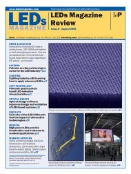
www.led-professional.com<br />
professional<br />
Review<br />
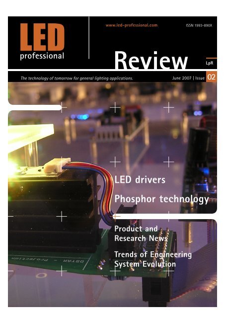
The <strong>technology</strong> of tomorrow for general lighting applications. June 2007 | Issue 02<br />
<strong>LED</strong> <strong>drivers</strong><br />
<strong>Phosphor</strong> <strong>technology</strong><br />
Product and<br />
Research News<br />
Trends of Engineering<br />
System Evolution<br />
ISSN 1993-890X<br />
LpR
Entry to a big<br />
market<br />
Copyright © 2007 Luger Research & <strong>LED</strong> professional. All rights reserved.<br />
According to the EOS conference held in Munich in mid June 2007,<br />
the market volume for <strong>LED</strong> lighting will rise from ~500 Mio US$ in<br />
2007 to ~900 Mio US$ in 2010 and will represent about 10% of<br />
the total global <strong>LED</strong> business volume.<br />
With a growth rate of about 40% per year the commercial area<br />
(shops, offices, etc.) based on High-Brightness <strong>LED</strong> technologies is<br />
the fastest growing sector in which white <strong>LED</strong> systems make up<br />
50% of the High-Brightness <strong>LED</strong> market. <strong>LED</strong> <strong>technology</strong> promotes<br />
new lighting systems on the basis of their aesthetic design<br />
potential, their robustness, their lack of radiated heat and UV-light,<br />
their easy driving functionality including dimming and colour<br />
changes and, last but not least, on the basis of the improved<br />
energy efficiency they offer.<br />
What is driving the market growth? The improvement in <strong>LED</strong> energy efficiency is driving<br />
growth. Further developments over the next few years are expected to improve luminous<br />
efficacy by a factor of 2 from the latest efficacy figures of 80-100 lm/W to the region of 160-<br />
180 lm/W. The choice of <strong>LED</strong> for a system is more than just peak luminous efficacy values. The<br />
complete system needs to be considered as phosphor efficiency degrades by about 5% lumens<br />
per 20K increase in temperature and <strong>LED</strong> life time is strongly dependent on <strong>LED</strong> junction<br />
temperature, life time is reduced from 50,000 hours to only 100 hours at 180°C junction<br />
temperature.<br />
For a <strong>LED</strong> system, the driver stage is a key for overall performance. Driver efficiencies vary<br />
between 80-95%, this means potentially up to 20% of energy could be lost in the supply /<br />
driver part. The core <strong>technology</strong> in <strong>LED</strong> drive modules is SMPS (switched mode power supplies).<br />
SMPS have been developed and optimized over years with specialist <strong>LED</strong> driver ICs providing<br />
the “intelligence” in the module. The new aspect of driving <strong>LED</strong>s is the requirement for voltage<br />
to current converter <strong>technology</strong>. <strong>LED</strong> drive modules on the market range from simple systems<br />
(circuits) where only one external inductor is needed to complex <strong>drivers</strong> with interfaces for<br />
external control are available. The choice of the driving technique is mainly based on required<br />
functionalities such as dimming, colour control, closed loop feedback system, however<br />
simplicity and Intellectual Property (IP) rights also play an important role in selecting the most<br />
appropriate technique. Finally there is always the big issue of system cost; with <strong>LED</strong>s costing<br />
about 100 lm/ US$, the driver stage, optics and thermal management have to be taken into<br />
consideration in order to develop new lighting solutions that will drive the market growth<br />
opportunity.<br />
With the June issue of the <strong>LED</strong> professional Review (LpR), <strong>LED</strong> <strong>drivers</strong> are covered in depth with<br />
a summary on phosphor developments that links with the article on white <strong>LED</strong>s in the last<br />
issue of LpR.<br />
Please send us your feedback about the LpR content. We would like to get your opinion on how<br />
to continuously improve our services to you.<br />
Yours Sincerely,<br />
Siegfried Luger<br />
Editor<br />
www.led-professional.com <strong>LED</strong> professional Review | June 2007 | page 2
www.led-professional.com<br />
Imprint<br />
<strong>LED</strong> professional Review (LpR)<br />
ISSN 1993-890X<br />
Free subscription for pdf version.<br />
Publisher<br />
Luger Research<br />
Institute for Innovation & Technology<br />
dep <strong>LED</strong> professional<br />
Rhombergs Fabrik<br />
A 6850 Dornbirn, Austria / Europe<br />
phone +43 5572 394 489<br />
fax +43 5572 394 698<br />
editors@led-professional.com<br />
www.led-professional.com<br />
Publishing Editors<br />
Siegfried Luger, EMBE<br />
Arno-Grabher Meyer<br />
Jasmine Leger, Dr.<br />
Creative Direction<br />
Thomas Ehgartner | DesignLab<br />
Königshofstraße 47, 6800 Feldkirch<br />
phone +43 5522 60000<br />
office@ehgartner.eu<br />
www.designlab.at<br />
Copyrights – Luger Research<br />
The editors make every reasonable effort to verify the<br />
information published, but Luger Research assumes no<br />
responsibility for the validity of any manufacturers, non<br />
profit organisations or individuals claims or statements.<br />
Luger Research does not assume and hereby disclaims any<br />
liability to any person for any loss or damage caused by<br />
errors or omissions in the material contained herein,<br />
regardless of whether such errors result from negligence,<br />
accident or any other cause whatsoever.<br />
Copyright © 2007 Luger Research & <strong>LED</strong> professional. All rights reserved.<br />
<strong>LED</strong> professional Review (LpR) -<br />
Annual Subscription for printed version<br />
Price: EUR 97.00 / USD 130.00<br />
Tax/VAT may be added for certain countries.<br />
Duration of the subscription: until cancelled<br />
Payment interval: every 12 months<br />
Shipment: Postal mail / 4 issues<br />
Language: English<br />
Send E-mail to:<br />
editors@led-professional.com<br />
Ref: Subscription<br />
LpR Issue – September 2007<br />
•<br />
•<br />
•<br />
Requirements for <strong>LED</strong> lighting<br />
systems<br />
New <strong>LED</strong> technologies<br />
<strong>LED</strong> <strong>drivers</strong> & sensors<br />
LpR Issue – November 2007<br />
•<br />
Thermal Management<br />
<strong>LED</strong> professional Review | June 2007 | page<br />
3
Content<br />
Editorial p 2<br />
Imprint p 3<br />
Product News p 6<br />
Research News p 10<br />
<strong>Phosphor</strong> Technology<br />
<strong>LED</strong> Driver<br />
The Right White: Recent developments in white phospors<br />
by Prof. R. J. Arthley, ETeCH Management GmbH p 11<br />
Driving <strong>LED</strong>s – A Real Challenge<br />
by Arno Grabher-Meyer, <strong>LED</strong> professional p 1<br />
Colour compensation:<br />
<strong>LED</strong> <strong>technology</strong> for colour constant RGB colour mixing luminaries<br />
by Thomas Schielke, ERCO Leuchten p 17<br />
Adding Intelligence to <strong>LED</strong> Lighting Systems<br />
by Steve Bowling, Microchip Technology Inc. p 20<br />
What’s your favourite colour?<br />
by Simon Bramble, austriamicrosystems Applications p 2<br />
Low Cost Power Supply for High Power <strong>LED</strong> Applications<br />
by Dr. Michael Weirich, Fairchild Semiconductor GmbH p 28<br />
Next Generation MR16 <strong>LED</strong> Lamps Powered by<br />
the MAX16820 Driver IC<br />
by Da Feng Weng and Mehmet Nalbant,<br />
Maxim Integrated Products Inc. p 32<br />
<strong>LED</strong> Lamps Require Integrated Power Conversion ICs To<br />
Meet EMC and Quality Standards<br />
by Silvestro Fimiani, Power Integrations p 35<br />
Trends of Engineering System Evolution<br />
S-Curve Analysis<br />
by Siegfried Luger, <strong>LED</strong> professional p 37<br />
www.led-professional.com<br />
Copyright © 2007 Luger Research & <strong>LED</strong> professional. All rights reserved.<br />
Advertising Index<br />
austriamicrosystems p 27<br />
Instrument Systems p 27<br />
Microchip p 21<br />
<strong>LED</strong> China 2008 p 19<br />
Power Vector p 3<br />
Prema Semiconductor p 23<br />
Tridonic.Atco p 16<br />
STMicroelectronics p 5<br />
Vossloh-Schwabe p 27<br />
<strong>LED</strong> professional Review | June 2007 | page
Solutions<br />
One lamp or a thousand <strong>LED</strong>s<br />
Flashlight, general lighting, traffic lights or jumbo color displays.<br />
The answer’s always the same:<br />
Total lighting control solutions from STMicroelectronics<br />
Flash YOUR <strong>LED</strong>s<br />
Most advanced Flash Driver STCF03:<br />
Dual mode buck-boost dc/dc converter<br />
1.8 MHz PWM control scheme<br />
Operating input voltage from 2.7 to 5.5V<br />
Flash mode: up to 800mA<br />
Torch mode: up to 200mA<br />
Flash and torch exponential dimming<br />
Flash intensity and duration programmable by I 2 C TM<br />
Part number Topology Iout Efficiency<br />
STCF03 Buck – Boost 800mA 92%<br />
STCF02 Buck – Boost 600mA 90%<br />
STCF01 Boost 300mA 90%<br />
Part number Description Iout VDD<br />
L6902D 250kHz, Step-down with<br />
integrated current control<br />
1A 8-36V<br />
L5970D 250kHz, Step-down 1A 4.4-36V<br />
L5970AD 500kHz, Step-down 1A 4.4-36V<br />
L5973AD 500kHz, Step-down 1.5A 4-36V<br />
L5973D 250kHz, Step-down 2A 4-36V<br />
LIGHTING<br />
Display YOUR <strong>LED</strong>s<br />
Features of the STPxxCP/DP05 Power Logic family<br />
4, 8, 16 channels, output currents are set by only one resistor<br />
Wide Current range from 5mA to 500mA per output channel<br />
Serial data and clock re-synchronized device by device<br />
VDD 3.3 or 5 V<br />
Derivatives with error detection or auto power saving.<br />
Part number Description Iout Precision<br />
Channel/ Chip<br />
STP04CM596 4 channels 500mA ±1% / ±6%<br />
STP08/16CP05 8/16-channels 100mA ±1.5% / ±5%<br />
STP08/16DP05 8/16-ch with error detection 100mA ±1.5% / ±5%<br />
STP16CPS05 16-ch with auto power saving 100mA ±1.5% / ±5%<br />
Power YOUR <strong>LED</strong>s<br />
Monolithic DC/DC converters<br />
Operating input voltage from 4V to 36V<br />
Up to 2A DC output current<br />
Internal current limit<br />
Inhibit for zero current consumption<br />
Integrated current control (L6902D)<br />
www.st.com/lighting<br />
led2.indd 1 15-06-2007 12:41:26
Product News<br />
Cree Announces<br />
Breakthrough 100-Lumen<br />
XLamp <strong>LED</strong>s Cree, Inc., a market leader in <strong>LED</strong> solidstate<br />
lighting components, announced<br />
commercial availability of XLamp®<br />
<strong>LED</strong>s with minimum luminous flux of<br />
100 lumens at 350 mA. XLamp <strong>LED</strong>s<br />
are the first <strong>LED</strong>s to be available in<br />
volume with this level of performance.<br />
This advance sets a new standard in<br />
lighting-class <strong>LED</strong> brightness and<br />
efficiency.<br />
XLamp <strong>LED</strong>s have now achieved a 100% improvement in performance<br />
over the past 17 months. They can deliver either 25% greater brightness<br />
with improved efficacy, or they can deliver up to 55% greater brightness<br />
at the same efficacy when compared to the previous generation of<br />
XLamp <strong>LED</strong>s. Moreover, the new XLamp <strong>LED</strong>s retain the same footprint<br />
as previous XLamp <strong>LED</strong>s, thereby protecting customers’ design<br />
investments.<br />
„Cree is to be congratulated on surpassing the 100-lumen level in its<br />
commercial white <strong>LED</strong> products,“ said Robert Steele, director of the<br />
optoelectronics practice at market research firm Strategies Unlimited.<br />
„The availability of such high-performance devices should certainly<br />
accelerate the conversion of the lighting market to solid-state<br />
sources.“<br />
“This is an announcement of volume availability, not an R&D result or<br />
availability of a few parts,” stated Norbert Hiller, Cree vice president and<br />
general manager for lighting <strong>LED</strong>s. “These <strong>LED</strong>s can enable lighting<br />
manufactures to create fixtures using fewer <strong>LED</strong>s than before, thereby<br />
lowering initial product cost and reducing energy consumption.”<br />
American Bright Opto-<br />
electronics Corporation announces<br />
new all metallic<br />
High Power <strong>LED</strong>s<br />
American Bright Optoelectronics announced the introduction of a full<br />
line high-power SMT <strong>LED</strong>s that feature all metallic composition including<br />
Copyright © 2007 Luger Research & <strong>LED</strong> professional. All rights reserved.<br />
a copper (Cu) circuit board and aluminum (Al) body/reflector. This new<br />
series features a wide range of standard attached optics and the options<br />
of being pre-mounted on industry standard star-style metal core<br />
printed circuit boards (MCPCB) or packaged in 250 piece reels. Stock<br />
viewing angles available range from the standard 110º degree discrete<br />
device with out a lens to 120º, 45º and 25º integrated lens versions and<br />
dual angle, or oval pattern lens versions in 90º/30º or 100º/50º.<br />
The integration of optics reduces design time dramatically and allows<br />
the design engineer to focus on integration of fewer component level<br />
devices. The integration also reduces assembly costs by eliminating<br />
post-secondary assembly steps including application of adhesives,<br />
bonding agents and cleaners while assuring proper alignment of the<br />
optic and emitter.<br />
The new series is available in the widest range of visible colors including<br />
460nm Blue through 620nm Red. White bin groups, in both cool white<br />
and warm white, are binned according to McAdams Ellipses and clearly<br />
defined in the comprehensive, 25 page, American Bright Optoelectronics<br />
data sheets and application notes. The full spectrum possibilities give<br />
designers in the Architectural Lighting, Automotive, Decorative, Portable,<br />
Traffic, Signage and Signaling industries a viable alternative to costly<br />
multi-component solutions currently employed industry wide.<br />
High–Power White <strong>LED</strong><br />
Knocks Down General Illumination<br />
Barriers<br />
The exclusive, new VIO high–power white <strong>LED</strong> from Lumination, LLC,<br />
GE Consumer & Industrial‘s <strong>LED</strong> business, uses proprietary violet–chip<br />
<strong>technology</strong> to produce less than a 100–Kelvin color shift over a 50,000–<br />
hour rated life. Its minimal color shift overcomes many of the inherent<br />
color control issues of standard blue or red–green–blue <strong>LED</strong> devices.<br />
www.led-professional.com <strong>LED</strong> professional Review | June 2007 | page 6
Lumination‘s VIO <strong>LED</strong> also provides high efficiency at warmer color<br />
temperatures, as well as flexible color temperature and color–rendering<br />
options.<br />
Lumination scientists create VIO high–power white <strong>LED</strong>s by combining<br />
405 nanometer violet chips with a proprietary blend of phosphors. The<br />
VIO violet chip operates at a higher efficiency wavelength than blue<br />
<strong>LED</strong>s. <strong>Phosphor</strong>s applied to the hemispherical lens of the VIO <strong>LED</strong><br />
convert its violet wavelength to white light. VIO <strong>LED</strong>s are offered in<br />
3500K and 4100K color temperatures that can be used in many standard<br />
fixtures designed for general illumination applications. „The availability<br />
of Lumination‘s VIO high–power white <strong>LED</strong> is a significant milestone on<br />
the path toward general illumination with GE–quality <strong>LED</strong>s,“ comments<br />
Kraig Kasler, vice president of marketing, Lumination, LLC. „Our<br />
investment in this major new product underscores the commitment we<br />
made earlier this year to pursue global distinction in the general<br />
illumination market. We think our violet–chip <strong>technology</strong> offers the best<br />
available control of color shift in white <strong>LED</strong>s.“<br />
Oftentimes, <strong>LED</strong>s used in fixtures produce glare or bright spots. The use<br />
of multiple point sources in fixtures (e.g., several <strong>LED</strong>s grouped together)<br />
has the potential to produce multiple shadows. VIO <strong>LED</strong>s eliminate such<br />
distractions. High–power, 4–watt VIO <strong>LED</strong>s distribute diffused light<br />
more evenly over a 180–degree beam angle.<br />
The color of Lumination‘s VIO high–power white <strong>LED</strong> is so stable that its<br />
light can be used with confidence as a replacement for traditional<br />
general illumination light sources.<br />
„With this new product, we‘re ushering in a new era for lighting fixture<br />
OEMs and designers,“ notes Kasler. „Incorporating <strong>LED</strong>s in a lighting<br />
scheme is more than a novel approach or smart move from an energy<br />
standpoint. Based on its performance, our VIO <strong>LED</strong> is a real alternative<br />
light source that will maintain a consistent appearance over a period of<br />
years.“ Potential applications for VIO <strong>LED</strong>s include general (pendant,<br />
sconce), commercial (task, display), landscape (pathway, in–ground)<br />
and architectural (wall wash, marker.) lighting.<br />
Copyright © 2007 Luger Research & <strong>LED</strong> professional. All rights reserved.<br />
Seoul Semiconductor<br />
Unveils Warm White Acriche<br />
of 42 lm/W<br />
Seoul Semiconductor announced that Acriche, the world’s first<br />
semiconductor lighting source for AC power outlets, can now achieve<br />
warm white of near-daylight quality, making it suitable for general and<br />
indoor lighting applications. The warm white Acriche features 42 lm/W<br />
based on light source.<br />
Actual System Efficiency – which takes into account luminous efficacy,<br />
ballast efficiency and luminaire efficiency – for the warm white Acriche<br />
is 39.9 lm/W. This is higher than 7.5 lm/W for incandescent lamps and<br />
30.6 lm/W for compact fluorescents.<br />
Warm white Acriche is a suitable replacement for DC-<strong>LED</strong> lighting.<br />
Compared to conventional warm white DC <strong>LED</strong> which has a luminous<br />
efficacy of nearly 35 lm/W, the warm white Acriche at 42lm/W is 20%<br />
more efficient. Warm white Acriche can also produce a brighter lighting<br />
environment without the need of a converter or ballast.<br />
Seoul Semiconductor has also released warm white Acriche with a<br />
luminous efficacy of 33 lm/W which has a Color Rendering Index (CRI)<br />
rating of 90. The CRI measures the ability of a light source to produce<br />
vibrant colors in objects. A CRI rating of 100 suggests that the light<br />
source is equivalent to daylight, while a low CRI rating near 0 suggests<br />
that colors will appear unnatural under that particular light source.<br />
Acriche Warm White’s high CRI ratings and superior color rendering<br />
capabilities make it an ideal solution for environments that demand<br />
vibrant and accurate lighting, such as museums, luxury hotels, art<br />
galleries, show rooms and displays.<br />
For many years, the ability to produce a warm white semiconductor<br />
lighting source that can also offer a high quality CRI rating had appeared<br />
illusive. Today, that hurdle has been successfully negotiated.<br />
“The need for alternative lighting sources has never been more pressing,”<br />
said Seoul Semiconductor CEO Cheong Hoon Lee. “Environmental<br />
www.led-professional.com <strong>LED</strong> professional Review | June 2007 | page 7
pollution and oil prices are rising, and the effects of mercury and lead<br />
continue to take a toll on our ecosystems. We hope to accelerate the<br />
move towards energy efficient and environmentally friendly lighting by<br />
producing alternative lighting sources such as warm white Acriche that<br />
can match the capabilities of conventional lighting sources, but with<br />
less harm to the environment and at a lower cost in terms of energy<br />
consumption.”<br />
Philips Lumileds LUXEON K2<br />
Warm and Neutral White<br />
<strong>LED</strong>s<br />
Philips Lumileds announced<br />
immediate availability of warmwhite<br />
and neutral-white LUXEON<br />
K2 emitters as well as a LUXEON<br />
K2 Star part that can be specified<br />
with any standard white emitter.<br />
The new white colors have typical<br />
correlated color temperatures<br />
(CCT) of 3000K and 4100K and a<br />
color rendering index (CRI) of 80<br />
and 75 respectively. The CCT range for LUXEON K2 now extends from<br />
2670K to 10,000K and a new finer color bin structure allows for better<br />
overall selection. Unlike most power <strong>LED</strong>s that are limited to 700mA,<br />
LUXEON K2 warm white and neutral white <strong>LED</strong>s can be run up to<br />
1500mA and a junction temperature of 150°C. The new warm-white<br />
and neutral white can deliver more than 130lm and 140lm respectively.<br />
LUXEON K2 delivers more usable light at virtually any drive current and<br />
junction temperature condition.<br />
“With the increases in light output performance and efficacy, there is<br />
expanding demand for power <strong>LED</strong>s that deliver the quality of light<br />
required for general lighting applications,“ said Steve Landau, Director<br />
of Marketing Communications. “Designers of residential applications,<br />
such as recessed can lights need uniformity, high color rendering and a<br />
warm white color temperature at 3000K. In many retail and commercial<br />
applications, a cooler temperature of 4100K is desired. With the new<br />
binning and phosphor technologies in LUXEON K2, the needs of lighting<br />
designers in both markets can be addressed.“<br />
Lighting designers consider several critical “quality of light“ factors<br />
when evaluating white <strong>LED</strong>s: color temperature (CCT), color rendering<br />
(CRI) and color uniformity are three of the most important. The new<br />
LUXEON K2 parts address CCT and CRI and Philips Lumileds phosphor<br />
expertise and technologies ensure the highest degree of color uniformity<br />
resulting in white <strong>LED</strong>s that are as much as 7 times more uniform that<br />
other white power <strong>LED</strong>s.<br />
Copyright © 2007 Luger Research & <strong>LED</strong> professional. All rights reserved.<br />
Introducing Fairchild<br />
Semiconductor‘s TinyBuck<br />
Fairchild Semiconductor introduces the FAN2106, the first product in a<br />
new family of TinyBuck DC-DC buck regulators that integrate an<br />
advanced analog IC, MOSFETs and a boot diode into an ultra-compact<br />
molded leadless package (MLP). Measuring only 5mm x 6mm, the<br />
FAN2106 is the industry’s smallest 6A, 24V-input integrated synchronous<br />
buck regulator on the market today. This highly integrated low-profile,<br />
small-footprint device consumes approximately 50 percent less board<br />
space than discrete solutions and facilitates greater design flexibility.<br />
Furthermore, the FAN2106 achieves up to 95 percent power efficiency<br />
by converting input of 3V through 24V input voltages to output voltages<br />
as low as 0.8V while delivering up to 6A output current. This compact,<br />
easy-to-use, high-efficiency regulator is ideal in a broad range of pointof-load<br />
(POL) applications. These include set-top boxes, cable modems,<br />
in-cabin GPSs, portable medical<br />
equipment, <strong>LED</strong> lighting, industrial<br />
instrumentation as well as ultramobile<br />
PCs, notebooks and blade<br />
servers.<br />
“Fairchild’s TinyBuck all-in-one<br />
module offers superior features<br />
that enable engineers to meet<br />
their primary design challenges:<br />
saving board space, simplifying<br />
designs and increasing power<br />
efficiency,” said Justin Chiang, vice president of Fairchild’s System Power<br />
Group. “As the first product in this new family, the FAN2106 integrates<br />
our latest DC-DC PWM controller with gate <strong>drivers</strong>, advanced MOSFETs<br />
and a boot diode into a tiny MLP package.<br />
PWM Dimming<br />
Linear Technology Corporation announces the LT3496, a 2MHz DC/DC<br />
converter designed to operate as a three-channel constant current <strong>LED</strong><br />
driver. Each of the LT3496’s three channels can drive up to eight 500mA<br />
<strong>LED</strong>s in series, enabling it to drive up to 24 x 500mA <strong>LED</strong>s at efficiencies<br />
up to 96%. All three channels are operated by an independent True<br />
Color PWM signal, enabling each to be dimmed independently to ratios<br />
as high as 3,000:1. A fixed frequency, current mode architecture ensures<br />
stable operation over a wide range of supply and output voltages. A<br />
frequency adjust pin enables the user to program the frequency between<br />
330kHz and 2.1MHz to optimize efficiency while minimizing external<br />
component size. The LT3496’s thermally enhanced 4mm x 5mm QFN<br />
package provides a highly compact solution footprint for 50W <strong>LED</strong><br />
applications.<br />
www.led-professional.com <strong>LED</strong> professional Review | June 2007 | page 8
The LT3496 senses output current at the high side of the <strong>LED</strong>, enabling<br />
buck, buck-boost or boost configurations. With an external sense<br />
resistor, the user programs the output current range of each channel.<br />
Each of the three independent driver channels utilizes an internal<br />
750mA, 45V NPN switch and has a built in gate driver for PMOS<br />
disconnect. Other features include open <strong>LED</strong> protection and thermal<br />
limiting.<br />
STMicroelectronics Introduces<br />
First Auto-Shutdown <strong>LED</strong><br />
Driver to Address Energy-<br />
Saving Programs<br />
STMicroelectronics, a leader in ICs for driving high-brightness (HB)<br />
<strong>LED</strong>s, introduced the first <strong>LED</strong> driver to include auto-power-saving<br />
features. The STP16CPS05, an innovative member of ST’s Power Logic<br />
(STP**CP/DP05, where ** is the number of bits 4, 8 or 16) family, allows<br />
manufacturers to meet the high power-efficiency requirements of<br />
industrial lighting, signage and transport applications, especially<br />
battery-powered <strong>LED</strong> panels by guaranteeing savings of 80% compared<br />
to existing solutions.<br />
An evolutionary advantage of this new Power Logic device is the new<br />
constant-current <strong>LED</strong> <strong>drivers</strong> allow the individual ICs to go into a<br />
shutdown mode when no active inputs are detected. As a result, the<br />
STP16CPS05 can save power without external intervention, making it<br />
the ideal solution to support all worldwide energy-saving programs<br />
which encourage power efficiency in lighting applications<br />
Fig. 1 A Pharmacy <strong>LED</strong> Display Crossoften found outside Pharmacies. Usually, these <strong>LED</strong> Displays drive<br />
monochrome <strong>LED</strong>s and RGB <strong>LED</strong>s in some applications. An example follows for the power-saving possibilities<br />
using the STP16CPS05.<br />
Estimated number of <strong>LED</strong> Drivers: 80 units <strong>LED</strong> <strong>drivers</strong> active at any one<br />
time: ~ 20%<br />
•<br />
•<br />
•<br />
Driving each High Brightness<br />
<strong>LED</strong>s at Io = 80mA, the<br />
I DD (ON) = 11.7mA (typ)<br />
I DD (Shut-down) = 100uA (typ)<br />
ICC(SHUT-DOWN) is 117 times<br />
less than ICC(ON)<br />
Using standard <strong>LED</strong> driver, all 80 <strong>drivers</strong> will consume high current<br />
(approx. 1A)<br />
Using STP16CPS05, only 16 will consumer high current<br />
(approx. 0.2A)<br />
This hypothesis gives an possible power-saving rating of 80%.<br />
Copyright © 2007 Luger Research & <strong>LED</strong> professional. All rights reserved.<br />
The STP16CPS05 Power Logic series features a clock and data resynchronization<br />
function, which is useful when the devices are<br />
connected in cascade. the STP16CPS05 can work with a power supply<br />
from 3.3V up to 5V; its output current is programmable from 5mA to<br />
100mA to suit applications requiring mid-current range. This highprecision<br />
<strong>LED</strong> control guarantees an industry-best’s output precision of<br />
±1.5% Bit-to-Bit and ±5% Chip-to-Chip over the output current range<br />
from 20mA to 100mA and covers the full wide temperature range of -<br />
40ºC to +125ºC.<br />
The IC also has the market-highest Vout of 20V. This IC is available in<br />
three package types, of which one, the thermally efficient exposed-pad<br />
TSSOP, comes with outstanding heat dissipation features of RthJC =<br />
37.5°C/W. When it comes to protection, this IC is ESD protected at<br />
2.5kV(HBM) and 200V(MM). And it is thermally-protected by an in-built<br />
Automatic Thermal-shutdown circuitry.<br />
Virtuoso dimming in a dual<br />
package<br />
Top-class dimming is the watchword of the K350 DALI RGB <strong>LED</strong><br />
converter and the C350 PWM 4-channel <strong>LED</strong> dimmer. Both control gear<br />
units by TridonicAtco GmbH & Co. KG, Dornbirn/Austria demonstrate<br />
their unique selling proposition with a dimming range of 0.1% to 100%,<br />
continuous dimming and load-independent control. These features are<br />
especially vital for colour mixing or for coloured effects using highlight<br />
output power<strong>LED</strong> RGB modules.<br />
The K350 DALI RGB <strong>LED</strong> converter has a built-in power supply unit and<br />
three <strong>LED</strong> output channels with a constant current of 350 mA and PWM<br />
modulation, each of which can be used to dim up to five RGB light<br />
emitting diodes. Because of its compact design, this control gear offers<br />
plenty of scope for luminaire design and integrates particularly well into<br />
spotlights. Because its housing is equivalent to those of the TE one4all<br />
digitally dimmable transformer and the powerControl PCI ballast, a<br />
www.led-professional.com <strong>LED</strong> professional Review | June 2007 | page 9
luminaire manufacturer can easily create a spotlight family for various<br />
light sources such as RGB <strong>LED</strong> modules, low-voltage halogen lamps or<br />
metal halide lamps. The result - a consistent stylistic idiom at less<br />
expense.<br />
Up to ten high-power <strong>LED</strong>s can be controlled on each of the four output<br />
channels of the <strong>LED</strong> C350 PWM 4-channel dimmer. This makes it possible<br />
to implement applications involving long lengths such as wallwashing<br />
lighting effects among others. The fourth channel extends RGB colour<br />
mixing possibilities; for example, an additional amber <strong>LED</strong> improves<br />
colour rendition considerably.<br />
With its slim-line design, the 4-channel dimmer is extremely suitable<br />
for installation in sections and luminaires. Its universal PWM input is<br />
ideal for easy integration into control systems, using the DMX protocol<br />
for instance. The 4-channel dimmer can also be combined with the <strong>LED</strong><br />
K211 DALI converter very easily.<br />
The K350 DALI RGB <strong>LED</strong> converter and the C350 PWM 4-channel <strong>LED</strong><br />
dimmer set new standards when it comes to RGB colour mixing. Here,<br />
TridonicAtco‘s emphasis is on perfect dimming.<br />
Research News<br />
Philips Lumileds Leads Response<br />
to Lighting Industry<br />
Needs with New Reliability<br />
Analysis Tools<br />
Philips Lumileds has introduced a new reliability analysis tool that for<br />
the first time enables lighting designers to confidently determine<br />
lifetime performance of <strong>LED</strong>s under different operating conditions.<br />
Philips Lumileds graphical representation of reliability allows designers<br />
to understand and evaluate the impact of temperature and drive current<br />
on lumen maintenance and failure rates of <strong>LED</strong>s. Historically, only simple<br />
lumen maintenance data (x% lumen maintenance at y-hours) has been<br />
available and that single piece of information has been limited in scope.<br />
Details of the new analysis are available in a white paper published<br />
today, Understanding power <strong>LED</strong> lifetime analysis. Providing<br />
comprehensive and statistically-relevant reliability performance data is<br />
a step towards bridging the communication gap between the <strong>LED</strong><br />
semiconductor world and the lighting community.<br />
Graphical representation clearly shows dramatic reliability performance<br />
differences between <strong>LED</strong>s from different manufacturers and allows<br />
designers and engineers to make a more fully informed decision.<br />
Simple lumen maintenance statements not enough to make intelligent<br />
lighting design decisions. When designing <strong>LED</strong>-based lighting systems,<br />
Copyright © 2007 Luger Research & <strong>LED</strong> professional. All rights reserved.<br />
engineers need to understand <strong>LED</strong> reliability in similar terms to those<br />
used when designing with conventional light sources. In addition,<br />
designers need extra information to predict the lifetime of <strong>LED</strong>s under a<br />
variety of operating conditions. Although a number of techniques to<br />
predict <strong>LED</strong> lifetimes have been proposed, none has generated<br />
sufficiently clear and unambiguous data for lighting engineers. Philips<br />
Lumileds graphical tool provides designers with information required to<br />
make decisions about product lifetimes, driver constraints, number of<br />
<strong>LED</strong>s required, and thermal management.<br />
www.led-professional.com <strong>LED</strong> professional Review | June 2007 | page 10
The Right White: Recent<br />
developments in white<br />
phosphors<br />
> Prof. R. J. Artley, ETeCH Management GmbH<br />
There has been recent interest concerning the announcements by<br />
various governments that incandescent light bulbs are to be phased out<br />
as hugely energy-inefficient (typically
The above calculation is on a likefor-like<br />
basis, but there is another<br />
significant difference between<br />
<strong>LED</strong>s and incandescent- and CFLlamps:<br />
with <strong>LED</strong>s it is easy to<br />
direct the light where needed, and<br />
not in any other direction. This<br />
limits light pollution, but more<br />
importantly it means that lighting<br />
can be ‘designed down’ to what is<br />
actually needed – and hence save<br />
even more energy and cost.<br />
The commercial prospects look good. By 2010, semiconductor-based<br />
light-emitting diodes (<strong>LED</strong>s), especially high-brightness (HB) versions,<br />
are expected to have made significant inroads into general illumination,<br />
to be a market worth $15 billion from $5.73bn in 2006 (CAGR 22%).<br />
Total unit shipment of <strong>LED</strong> devices is expected to reach 64 billion in<br />
2010 from 27.4 billion in 2005 (IC Insights).<br />
So what happens next? Improvements in quality are what are needed.<br />
The major drawback of most conventional ‘white’ <strong>LED</strong>s is that they are<br />
not truly white, but are phosphor-coated (PC<strong>LED</strong>s), made from blue<br />
<strong>LED</strong>s (450-470nm, InGaN) with a coating of a yellow phosphor (chiefly<br />
yttrium aluminium garnet activated with cerium, Y3(Al,Si)5O12:Ce<br />
(YAG:Ce), which is a saturated colour with a peak at 570-573nm). These<br />
look white, but do not provide true white light across the visible<br />
spectrum. They provide ‘cold’ white light (colour coordinated temperature<br />
(CCT) 6000K), which most people do not favour for domestic lighting,<br />
and in particular they have very poor colour rendition in the red region<br />
of the spectrum. When this is measured by the standard full colour<br />
rendering index (CRI) which uses the full set of 14 or 15 colours (not just<br />
the ‘short set’ of 8 colours), some current ‘white’ <strong>LED</strong>s actually negatively<br />
score (out of 100) on measurements with Plate 9 – the strong red. The<br />
graph below illustrates this (CIE coordinates) – the mixture of a blue <strong>LED</strong><br />
and a white phosphor can look white, and can illuminate any colour<br />
between them (in the triangle towards the top of the diagram, although<br />
the more saturated colours, especially the greens, are also weak) – but<br />
not, properly, ones which are more orange or red (those below the<br />
line).<br />
Improvements to such <strong>LED</strong>s are needed to provide the full colour gamut<br />
(range of colours), and the most obvious way is to add a pinch of red<br />
phosphor (usually a nitride). Unfortunately since this is likely to be a<br />
different material, it is likely to age and change colour over time at a<br />
different rate from the yellow phosphor (or the blue <strong>LED</strong>) and so the<br />
light shifts colour over time.<br />
There are other approaches, of course. Combining red, green and blue<br />
<strong>LED</strong>s is one, although expensive. Sometimes these can be combined in<br />
the same chip – when Nichia Corp. of Japan first created white <strong>LED</strong>s<br />
(using augmented light from blue chips) in 1993 it used gallium nitride<br />
and indium gallium nitride, but almost no <strong>LED</strong>s are produced using this<br />
method today; although the University of California at San Diego is<br />
Copyright © 2007 Luger Research & <strong>LED</strong> professional. All rights reserved.<br />
researching phosphorless heterostructures based on InGaAlN:Ce;<br />
Georgia Tech is working on similar lines. Another method used to<br />
produce white light <strong>LED</strong>s also uses no phosphors and is based on<br />
homoepitaxially grown zinc selenide (ZnSe) on a ZnSe substrate which<br />
simultaneously emits blue light from its active region and yellow light<br />
from the substrate. This is also rather red-deficient. There is also<br />
interest in organic light-emitting diodes (O<strong>LED</strong>s), noting in particular<br />
the efficiency improvements made using these with white phosphors,<br />
by Prof. Stephen Forrest (ex Princeton, now University of Michigan in<br />
Ann Arbor) together with Prof. Mark Thompson (University of Southern<br />
California in Los Angeles).<br />
A better solution than all the above would thus be a single, truly ‘white’<br />
phosphor, which would give true representation of all colours. This<br />
would probably be activated not by a blue <strong>LED</strong> (because of the difficulties<br />
of balancing the direct and indirect light, especially over time – one<br />
tends to end up with better reds but poorer greens), but by UV light<br />
(just as in the CFLs) from a UV <strong>LED</strong>. There is fundamentally a greater<br />
loss in conversion of UV to white light than blue light to white light (this<br />
is called the ‘Stokes shift’), but on the other hand UV <strong>LED</strong>s are much<br />
more energy-efficient than blue <strong>LED</strong>s, so they tend to be slightly better<br />
overall. They are also being rapidly improved - the first UV <strong>LED</strong>s (under<br />
380nm) were demonstrated as recently as April 2002 – less than five<br />
years ago - by Nitride Semiconductors and (separately) PARC (Xerox,<br />
Palo Alto) and Crystal IS (AlGaN): such UV <strong>LED</strong>s have only been<br />
commercial since 2004 (Nichia) and 2005 (Nitride Semiconductors,<br />
others). This is important since there is a great deal of experience in the<br />
fluorescent lamp industry in converting from the mercury lines at<br />
366nm.<br />
There is thus a race to create a good, ‘warm white’ (5000K, similar to<br />
solar) single-material phosphor, in which several dozen companies and<br />
academic establishments are competing. A single phosphor, it is<br />
expected, would not have the problems of different aging cycles of<br />
mixed systems, but any candidate needs to be highly luminescent,<br />
highly energy-effective, and highly stable to be considered commercially<br />
viable.<br />
It’s probably appropriate here to give a short background to phosphors,<br />
to illustrate the enormous possibilities being explored. <strong>Phosphor</strong>s<br />
fundamentally consist of ‘hosts’ (inorganic crystalline materials) and<br />
‘activators’ (transition metals (TM) and rare earth metals (REM)), and,<br />
optionally, ‘sensitizers’ (similar). The ‘hosts’, conventionally, are usually<br />
oxides although nitrides, silicates, aluminates and sulphides are also<br />
used: other systems such as halides (fluorides, chlorides), yttrates,<br />
gallates etc. have been either largely unexplored or have historically<br />
been considered ‘difficult’ to work with. However this is where some of<br />
the most exciting new discoveries are being made. With so many<br />
possible combinations – some hundreds if not thousands of phosphors<br />
(of varying effectiveness and colour) are known - this is still a rich field<br />
of exploration.<br />
Light emission from phosphors happens by energy absorption by the<br />
host, sensitizer, or activator directly, transfer of energy to the activator,<br />
www.led-professional.com <strong>LED</strong> professional Review | June 2007 | page 12
and emission, any spare energy showing up as heat. Normally, for light<br />
stimulation, ‘down-conversion’ of more energetic light (UV, blue) to less<br />
(yellow, red), occurs. The choice of activator determines the range of<br />
colours of light which is emitted: for lighting, ‘broad band’ is desirable,<br />
which is achieved by using the lower oxidation states of TM or REM, e.g.,<br />
Eu2+ or Sn2+.<br />
Probably the first publicly announced single white phosphor (July, 2005)<br />
was that from the group of Prof. Sue-Lein Wang at the National Tsing<br />
Hua University, Hsinchu, Taiwan. This was zinc gallophosphate, laced<br />
with nanoscale pores, where the white light seems to stem from blue<br />
fluorescence in highly ordered regions of the material, combined with<br />
yellow emission where it is more disordered. Unfortunately it does not<br />
appear that any quantitative data has yet been published on this, so the<br />
questions of its luminance, efficiency and stability as yet remain open.<br />
Many centres are looking at the possibilities of zinc oxide, amongst<br />
others the Universities of Bristol, California–Riverside, Florida,<br />
Gothenburg (nanowires), Hanoi, Hsinchu (Industrial Technology<br />
Research Institute), and Tohoku. Zinc oxide can be a white-emitting<br />
material, but it is proving very difficult to gain suitably high energy<br />
efficiencies from it (remember 100 lm/W is the target).<br />
Some of the latest research has centered on ‘quantum dots’, or<br />
nanocrystals of phosphors or semiconductors (usually III-V types),<br />
where ‘tuneable’ changes in their physical size adjust the light frequencies<br />
output. Each size emits one colour, but of course a mixture of sizes can<br />
emit white or near to it. Centres of research into this phenomenon<br />
include Cranfield University (UK), the Naval Research Laboratory (USA),<br />
and Vanderbilt University (USA), which is looking at CdSe nanocrystals:<br />
these are also the subject of a cooperation between the University of<br />
Chicago, Corning and NYSTAR. The University of Texas (in cooperation<br />
with Innovalight) is looking at silicon nanocrystals as high energy white<br />
phosphors.<br />
In more conventional phosphors, the silicates are attracting attention.<br />
Niigata University (Japan), in cooperation with Sumitomo Chemical Co.<br />
Ltd., is researching europium-doped silicate phosphors for white <strong>LED</strong>s:<br />
Li2SrSiO4:Eu(2+), Ba9Sc2Si6O24:Eu(2+), Ca3Si2O7:Eu(2+), and<br />
Ba2MgSi2O7:Eu(2+). Unfortunately again little quantitative data has<br />
yet been published. The University of Georgia is likewise looking at<br />
strontium silicates Sr2SiO4:Eu2+, (normally a yellow phosphor) in<br />
cooperation with GE, and NIMS (the National Institute for Materials<br />
Science, Japan) is considering Li-SiAlON (used with InGaN sources) in<br />
cooperation with Fujikura Ltd / Sharp Corp. Litec-LLL GmbH, (Griefswald<br />
Germany) is also looking at advanced silicate phosphors for improved<br />
white <strong>LED</strong>s, chiefly Ba2-x-y-zSrxCaySiO4:Eu2+z (BOSE).<br />
ETeCH 2 has its own development programme for white phosphors, in<br />
cooperation with the Vienna University of Technology, the University of<br />
Geneva, the West Switzerland University of Applied Sciences, Yverdon,<br />
and EPFL Lausanne, which has generated a number of interesting novel<br />
phosphors, including two single-material white phosphors. The lead<br />
compound, Ba7F12Cl2:Eu(II), is already showing 45 lm/W in unoptimised<br />
samples (CCT 5000k), and 100lm/W is confidently expected: the second<br />
Copyright © 2007 Luger Research & <strong>LED</strong> professional. All rights reserved.<br />
material, a specially co-doped form of strontium orthosilicate, Sr2SiO4<br />
[Eu(II),La(III)], is also showing good performance when stimulated by<br />
350-400nm ultra-violet (UV) light-emitting diodes (<strong>LED</strong>s). The novel<br />
materials convert the UV into visible light with a broad spectrum, thus<br />
enabling compact, highly efficient, low-cost lighting. There have also<br />
been various two-component white systems developed, and also various<br />
novel coloured materials have also been discovered and are being tested.<br />
The ongoing work (in collaboration with various industry partners) is to<br />
improve the reproduction of materials on larger scales, and optimization<br />
of particle size / coating thickness / match to <strong>LED</strong> sources. The materials<br />
and their use in lighting systems have been patented and filed for patent<br />
worldwide: the patents concerning Ba7F12Cl2, Eu(II) (BA7) are already<br />
granted for major territories worldwide.<br />
BA7 light output<br />
Spectrum and cromaticity diagram of BA7<br />
1 http://www.blackenergy.com/store/images/specs/light_levels_lumens.html and other sources<br />
2 http://www.etech.ch<br />
www.led-professional.com <strong>LED</strong> professional Review | June 2007 | page 13
Driving <strong>LED</strong>s –<br />
A Real Challenge<br />
> Arno Grabher-Meyer, <strong>LED</strong> professional<br />
Selecting the right design to drive a <strong>LED</strong> system is easy, isn’t it?<br />
– Choose a <strong>LED</strong>, take a voltage source and limit current with a<br />
resistor. For several years it was done in that way. Can that be so<br />
wrong?<br />
Yet modern, efficient and high quality <strong>LED</strong> systems are far more complex<br />
and challenging than former applications, when <strong>LED</strong>s were mostly used<br />
as indicator lights. We have to imagine, that there are a lot of different<br />
applications with many conceptual paths. <strong>LED</strong>s can be used as<br />
replacement for low voltage halogen light or high voltage halogen light,<br />
but also to design revolutionary new luminaries for office lighting or<br />
residential lighting, a wall washer or floodlight, etc.<br />
For the electronic designer the differentiation starts with the chosen<br />
<strong>LED</strong>s for the particular application. To achieve an optimum result<br />
individual solutions are necessary, e.g. arrays of mid power <strong>LED</strong>s require<br />
other electronics than a single or a few high power <strong>LED</strong>s. A lot of<br />
additional questions have to be answered before the design process can<br />
be started:<br />
Will the <strong>LED</strong>s be driven in series or in parallel? Is the design based on<br />
<strong>LED</strong>s of the similar colour and type, or is it a multicolour design for<br />
adaptation of CCT, CRI or colour effects? What are the real requirements<br />
for the light quality, the dimming range, the colour stability over time,<br />
the light output? How to take in account degradation over time or<br />
thermal issues?<br />
Besides application specific questions there are some really basic<br />
problems that engineers are confronted with. These are the real<br />
challenges that are partly new in the field of lighting electronics:<br />
Improve electrical efficiency<br />
At the International „Workshop on Status, Prospects and Strategies for<br />
<strong>LED</strong>s in General Lighting 2007” Dr. Geoff Archenhold from SSLRC stated<br />
“A <strong>LED</strong> fixture is more than just a <strong>LED</strong>, it’s a system!” Improvement of<br />
driver efficiency from 80% to 88% results in a 5% increase of system<br />
efficacy. Considering the struggle of the European Community for CO2<br />
reduction this 5% improvement is not negligible.<br />
There are numerous contradictions that can hinder or constrict<br />
optimization of efficiency:<br />
•<br />
•<br />
A big difference between Mains voltage and secondary output<br />
voltage.<br />
Needs for a specific driving mode, because light quality would<br />
suffer.<br />
Copyright © 2007 Luger Research & <strong>LED</strong> professional. All rights reserved.<br />
DRIVER MODULE MANUFACTURERS<br />
AbstractAvr http://www.abstractavr.com<br />
Acro Engineering Inc. http://acro-powers.com<br />
Advance http://www.advancetransformer.com<br />
Aurora Ltd http://www.aurora.eu.com<br />
CML Innovative Technologies http://www.cml-it.com<br />
Erea nv http://www.erea.be<br />
Insta Elektro GmbH http://www.insta.de<br />
L.C. Relco S.p.A http://www.relco.it<br />
Lightech Electronic Industries http://www.lightech.co.il<br />
Lumotech Holland BV http://www.lumotech.com<br />
<strong>LED</strong>dynamics http://www.leddynamics.com<br />
Magtech Industries Corp. http://www.magtechind.com<br />
Mean Well Enterprises Co. http://www.meanwell.com<br />
Nobilé AG http://www.nobile.de<br />
OSRAM GmbH http://www.osram.de<br />
Paulmann http://www.paulmann.de<br />
Permlight Corporation http://www.permlight.com<br />
Power Vector http://www.powervector.com<br />
Prism Audio Ltd http://www.prismaudio.co.uk<br />
Tridonic.Atco http://www.tridonicatco.com<br />
www.led-professional.com <strong>LED</strong> professional Review | June 2007 | page 14
Reliability of electronics<br />
The quality of driver electronics has to be on a very high level to compete<br />
with lifetime of the <strong>LED</strong>s. Especially for embedded systems when the<br />
driver and <strong>LED</strong>s are mounted on the same circuit board this is<br />
necessary:<br />
•<br />
Passive electronic components sometimes don’t have the lifetime<br />
or robustness of <strong>LED</strong>s.<br />
Save system operation<br />
The driver electronics should prevent damage of the <strong>LED</strong>s because of<br />
thermal issues under all circumstances.<br />
•<br />
Closed loop feedback systems, with voltage and current control<br />
and thermal sensors are necessary.<br />
Dimming capability<br />
Dimming opportunities are desirable for white <strong>LED</strong> lighting and in<br />
particular for RGB, RGBW or RGBA <strong>LED</strong> clusters to adjust colour, CCT<br />
and CRI. The free choice of colour or CCT is one of the most interesting<br />
features of <strong>LED</strong> lighting.<br />
•<br />
•<br />
•<br />
•<br />
Costs<br />
Analogue dimming leads to colour drift.<br />
For 1% dimming a RGB system covering the full colour range<br />
PWM duty cycle must have a range of about 1:10.000.<br />
Switching losses of a PWM system stay almost constant at low<br />
dimming levels, hence system efficacy decreases.<br />
For highly accurate lighting systems costly closed loop feedback<br />
systems with optical sensors are necessary.<br />
Depending on the application costs are very critical, especially for<br />
replacement of today’s low voltage halogen systems high quality low<br />
cost solutions are necessary.<br />
•<br />
•<br />
Replacement: AC/DC 12V systems with magnetic transformers and<br />
switch mode power supplies must be served.<br />
Replacement: Dimming should be possible anyways.<br />
Copyright © 2007 Luger Research & <strong>LED</strong> professional. All rights reserved.<br />
Patent infringement<br />
Lots of patent applications for <strong>LED</strong> systems were published during the<br />
last decade. Many are really basic that some technician wonders that<br />
they were granted, others are really ingenious and it is hard not to use<br />
the presented solution:<br />
For many applications PWM would be the first choice, but for<br />
some applications this <strong>technology</strong> is blocked by the CK patent<br />
US6016038.<br />
Calculation and transformation algorithms for fast and accurate<br />
colour settings are also blocked by different granted patents.<br />
DRIVER IC MANUFACTURES<br />
Allegro MicroSystems, Inc. http://www.allegromicro.com<br />
Austriamicrosystems http://www.austriamicrosystems.com<br />
Clare Micronix http://www.claremicronix.com<br />
Dialog Imaging Systems GmbH http://www.diasemi.com<br />
FAIRCHILD Semiconductor<br />
GmbH<br />
http://www.fairchildsemi.com<br />
International Rectifier http://www.irf.com<br />
Linear Technology Corporate http://www.linear.com<br />
Maxim Integrated Products,<br />
Inc.<br />
http://www.maxim-ic.com<br />
Micrel Inc. http://www.micrel.com<br />
Microchip Technology Inc. http://www.microchip.com<br />
Monolithic Power Systems http://www.monolithicpower.com<br />
National Semiconductor http://www.national.com<br />
NXP Semiconductors http://www.nxp.com<br />
ON Semiconductor http://www.onsemi.com<br />
Power Integrations http://www.powerint.com<br />
Sipex Corporation http://www.sipex.com<br />
STMicroelectronics http://www.st.com<br />
Supertex Corporate http://www.supertex.com<br />
TOKO Ltd.<br />
http://www.toko.co.jp/top/en/index.<br />
html<br />
Vishay Inter<strong>technology</strong>, Inc http://www.vishay.com<br />
Zetex Semiconductors plc http://www.zetex.com<br />
www.led-professional.com <strong>LED</strong> professional Review | June 2007 | page 15<br />
•<br />
•
<strong>LED</strong>s.<br />
The next dimension in lighting <strong>technology</strong>.<br />
www.tridonicatco.com<br />
Ster Century Thessaloniki, Grecia<br />
power<strong>LED</strong> EOS P216<br />
power<strong>LED</strong> EOS P211<br />
High quality of light, high efficiency, more<br />
colour, greater dynamics – and all with<br />
exceptional economy. With power<strong>LED</strong><br />
from TridonicAtco you have greater<br />
control over light. For architecture and<br />
object lighting, for illuminated signage<br />
and emergency lighting, for traffic systems<br />
and for industrial applications. As<br />
a pioneer of chip-on-board <strong>technology</strong><br />
and dynamic lighting, TridonicAtco has<br />
developed power<strong>LED</strong> for maximum life<br />
and perfect output. See for yourself – at<br />
www.tridonicatco.com<br />
<strong>LED</strong> Converter <strong>LED</strong> Controls<br />
Accessories<br />
<strong>LED</strong> Chain P515
Colour compensation:<br />
<strong>LED</strong> <strong>technology</strong> for colour<br />
constant RGB colour<br />
mixing luminaires<br />
> Thomas Schielke, ERCO Leuchten<br />
Lighting designers have always used coloured light to add emphasis or<br />
provide atmospheric effects. This was done using coloured lamps or<br />
luminaires with colour filters, but thanks to electronically controlled<br />
RGB colour mixing luminaires it is now possible to produce any colour<br />
of light with <strong>LED</strong>s. Using colour compensation, the luminaire manufacturer<br />
is able to compensate for the deviations in luminous flux and<br />
hue due to the manufacturing tolerances of <strong>LED</strong>s, and thus to satisfy<br />
the highest demands of designers for uniformity, e.g. for coloured<br />
wall-washing.<br />
<strong>LED</strong>s and deviations in manufacture<br />
High colour saturation is one of the characteristic properties of <strong>LED</strong>s.<br />
However, the actual colour of the individual <strong>LED</strong>s is determined by two<br />
factors that are subject to certain manufacturing fluctuations: the<br />
luminous flux and the dominant wavelength. In practice this means that<br />
the colours of light from two identical <strong>LED</strong> luminaires can in fact deviate<br />
from one other. Semiconductor manufacturers classify every <strong>LED</strong><br />
according to these two criteria, sorting them into different categories<br />
called “binnings”. Some luminaire manufacturers demand that their<br />
suppliers provide binnings that are particularly stringently selected with<br />
respect to the dominant wavelength. This is because the greater the<br />
accuracy with which an individual light source emits a certain wavelength<br />
from the outset, the more exact the match between light colours of<br />
several luminaires. But even with the most stringent selection, deviations<br />
in both the luminous flux and the dominant wavelength between<br />
individual <strong>LED</strong>s of one colour still have to be accepted.<br />
Colour mixing and perception of<br />
differences in colour<br />
The problem of the manufacturing deviations of <strong>LED</strong>s is aggravated<br />
when mixed colours of light are used. In RGB colour mixing, the<br />
tolerances of two of three <strong>LED</strong>s are compounded together. On the one<br />
hand, the dominant wavelength can deviate by 5nm or more within one<br />
binning, depending on the manufacturer; on the other, fluctuations of<br />
20 to 30% can arise for one luminous flux binning. This means that the<br />
mixed colour of two <strong>LED</strong> luminaires can differ by more than 10nm in a<br />
worst-case scenario. The eye, however, can detect differences starting<br />
from 1-3nm, depending on the wavelength and the background.<br />
Therefore, high-quality colour mixing for architectural lighting with<br />
Copyright © 2007 Luger Research & <strong>LED</strong> professional. All rights reserved.<br />
several luminaires cannot be reliably implemented on this basis.<br />
Achieving colour constancy between several luminaires when<br />
washlighting a white wall – especially with an amber or cyan hue – is<br />
one of the most demanding challenges facing lighting engineering. The<br />
eye has a very high sensitivity for these wavelengths and therefore<br />
detects even fine differences in colour.<br />
From the technical side, fluctuations in luminous flux are more serious<br />
than fluctuations in dominant wavelength for the perception of the<br />
colour differences. Without colour compensation <strong>technology</strong>, this could<br />
cause the light colours produced by RGB colour mixing to visibly deviate<br />
from one luminaire to the next for the same DALI (Digital Addressable<br />
Lighting Interface) control values. Conversely, lighting users require<br />
lighting products that will always reproduce exactly the same light<br />
colour from a given DALI control value – even in difficult applications<br />
such as strip lighting or a row of <strong>LED</strong> luminaires acting as wallwashers.<br />
To ensure reliable colour precision, a colour compensation <strong>technology</strong>,<br />
is introduced whereby <strong>LED</strong> luminaires with RGB colour mixing capability<br />
(also known as varychrome luminaires) are individually measured and<br />
calibrated at the factory.<br />
Fig. 5: Coloured wallwashing without colour compensation<br />
Fig. 6: Coloured wallwashing with colour compensated Quadra varychrome <strong>LED</strong> luminaire<br />
www.led-professional.com <strong>LED</strong> professional Review | June 2007 | page 17
Colour compensation process<br />
The colour compensation is performed in four steps: i) the luminaires<br />
are operated for a certain time period; ii) their actual values are recorded;<br />
iii) compensation values are entered and iv) the compensation is<br />
checked. To achieve a reliable and constant value for the measurement,<br />
the luminaires are operated continuously for about two hours under<br />
reproducible temperature conditions until the luminaire reaches thermal<br />
saturation. Following this, a computer-aided measuring instrument<br />
records the luminous flux and the dominant wavelength for each of the<br />
luminaire’s RGB channels. In the third step, the measured values are<br />
compared with the set values. The software then calculates the<br />
compensation factors from these figures and permanently stores the<br />
result in the control gear. The set values are adjusted at certain<br />
production cycles to keep them up to date with technological progress.<br />
This will enable adjustment to suit the increasing luminous flux of future<br />
<strong>LED</strong>s. The resulting product versions are identified on the label of the<br />
luminaire to ensure that it can be reordered or reproduced as and when<br />
required. Colour compensation <strong>technology</strong> comes into play on luminaires<br />
featuring their own control gear where the compensation factors can<br />
be individually stored. Colour compensation, control gear and <strong>LED</strong><br />
module are seen here as a single unit and can be replaced as a single<br />
unit in a luminaire as and when necessary. Colour compensation is used,<br />
for instance, for spotlights or wallwashers in the indoor area or for<br />
outdoor luminaires such as projectors, in-ground luminaires or facade<br />
luminaires.<br />
�<br />
����� ���������<br />
�����<br />
����� ������<br />
Fig. 7: Colour compensation process diagram<br />
������� ���� ������<br />
�������� ����<br />
������<br />
��������<br />
��������<br />
�������� ����<br />
Encoded DALI control gear<br />
�� ���� ��������� ��<br />
��������� ������ ���<br />
����� ������ ��� ����<br />
�������<br />
The Light System DALI uses encoded DALI control gear, using which the<br />
central DALI controller automatically identifies the luminaires and their<br />
properties and enables the user-friendly functions. Various data<br />
(including the article number, a unique luminaire ID and an index for<br />
identifying the lamp type and lamp colour) is saved in the 16-byte<br />
memory of the DALI control gear to provide unique identification within<br />
the system. The advantage of the encoded DALI control gear is<br />
particularly apparent when implementing coloured lighting installations<br />
with luminaires featuring RGB colour mixing <strong>technology</strong>. These<br />
luminaires have three addresses with which the light colours red, green<br />
and blue are already assigned to the respective control gear. Compared<br />
Copyright © 2007 Luger Research & <strong>LED</strong> professional. All rights reserved.<br />
with conventional DALI systems, this does away with the time consuming<br />
task, performed on site, of assigning the addresses to the luminaires<br />
with their respective colour channels and control gear. A light colour<br />
can now be selected and assigned to several luminaires via the software.<br />
The <strong>LED</strong> compensation factors stored in the control gear are used to<br />
compensate for the deviations in the <strong>LED</strong>s, due to their manufacturing<br />
process, so that the user always receives a uniform colour of light.<br />
Output comparison of RGB colour<br />
mixing luminaires<br />
The prerequisite for colour mixing luminaires is to have lighting tools<br />
with individually dimmable light sources in the primary colours of red,<br />
green and blue as components of additive colour mixing. Coloured<br />
fluorescent lamps but also <strong>LED</strong>s in particular are suitable for this task.<br />
The saturation of the individual primary colours will determine the<br />
usable colour space. Due to their operating principle, <strong>LED</strong>S have one<br />
advantage over colour mixing luminaires with fluorescent lamps: their<br />
very high colour saturation produces a large colour space, which also<br />
includes highly saturated mixed colours. A quantitative output<br />
comparison of <strong>LED</strong> colour mixing luminaires should therefore not be<br />
based on the maximum luminous flux for white mixed light but on the<br />
entire spectrum and the saturation. Colour compensation allows the<br />
luminaire manufacturer to ensure that the user obtains the same hue on<br />
several adjacent luminaires; however, the trade off for this is that, in<br />
practice, the luminous flux can be slightly below the <strong>LED</strong> module’s<br />
maximum possible level.<br />
Summary<br />
Colour compensation <strong>technology</strong> for colour mixing luminaires with<br />
<strong>LED</strong>s makes it possible to compensate for the luminaire’s manufacturing<br />
tolerances and to achieve optimum lighting quality for the user. Even<br />
when <strong>LED</strong> binnings of the highest grade are sourced, the variation of<br />
both the maximum luminous flux and the dominant wavelength still<br />
represents a real problem for discerning architectural lighting solutions.<br />
Compensation factors stored in each luminaire’s own control gear<br />
ensure a uniform colour of light for luminaires of the same type during<br />
operation. In addition, the version control also takes the technical<br />
progress of the increasing luminous flux into account and improves the<br />
reordering process for subsequent deliveries.<br />
www.led-professional.com <strong>LED</strong> professional Review | June 2007 | page 18
Adding Intelligence to <strong>LED</strong><br />
Lighting Systems<br />
> Steve Bowling, Microchip Technology Inc.<br />
The latest generations of small, low-cost microcontrollers (MCUs) can<br />
be used to implement various types of electronic control in lighting<br />
power supply systems. They can improve control and efficiency, as well<br />
as providing intelligence for closed-loop monitoring and<br />
communication.<br />
For example, <strong>LED</strong> <strong>technology</strong> has now evolved to a point where it<br />
provides a durable source of light with efficiencies exceeding those of<br />
incandescent bulbs. An MCU added to an <strong>LED</strong> lighting system provides<br />
the ability to efficiently control brightness over the entire operating<br />
range. It also provides additional benefits such as active power factor<br />
correction (PFC) to further increase efficiency, battery charging for<br />
portable lighting applications and the opportunity to integrate popular<br />
communication protocols, such as DALI or DMX512<br />
The California Energy Commission has performed a comprehensive<br />
study to document lighting energy usage. This shows that residential<br />
lighting consumes 8 percent of all energy used by the state, while<br />
commercial lighting consumes 14 percent.<br />
The efficiency of a light source, or efficacy, is defined as the amount of<br />
light output divided by the electrical input power. The light output is<br />
measured in lumens. The efficacy of several types of light sources is<br />
shown in Figure 1.<br />
Figure 1: Efficacy of various light sources<br />
The incandescent light bulb is still widely used in residential applications.<br />
The California data shows that 59 percent of all residential lighting<br />
energy and 13 percent of all commercial lighting energy is consumed by<br />
incandescent sources. However, the incandescent bulb offers the lowest<br />
efficacy of all electrically-powered sources.<br />
Copyright © 2007 Luger Research & <strong>LED</strong> professional. All rights reserved.<br />
The high-power <strong>LED</strong><br />
The <strong>LED</strong> has been widely used in indicator applications for many years.<br />
These are low-current, low-power devices that are not very suitable for<br />
lighting applications. Recent advances in semiconductor manufacturing,<br />
silicon structures and phosphor coatings have made the high-power<br />
<strong>LED</strong> a possibility.<br />
Today’s power <strong>LED</strong> has an efficacy that approaches or exceeds other<br />
efficient light sources. However, it also has other benefits, including<br />
long lifetime and resistance to shock and vibration. These make it useful<br />
for applications such as traffic signs, automotive lighting, military<br />
applications and any place where safety, reliability or the cost of<br />
maintenance is an issue.<br />
A power <strong>LED</strong> is manufactured with a silicon-carbide or sapphire<br />
substrate. The sapphire substrate offers a lower manufacturing cost,<br />
but has a higher thermal resistance. The lower thermal resistance of<br />
silicon carbide is attractive for power <strong>LED</strong> applications. The substrate<br />
can then be doped with AlInGaP to make <strong>LED</strong>s in the red, orange or<br />
yellow colour ranges, or with AlInGaN to make green, blue or white<br />
devices.<br />
The ability to make a white light source with an <strong>LED</strong> is very important<br />
for lighting applications. Two common methods are used. The first is to<br />
use a blue <strong>LED</strong> with a phosphor coating that creates a white light. The<br />
other is to use an <strong>LED</strong> that emits light in the ultra-violet range. A mix of<br />
red, green and blue phosphors is then used to turn this into visible white<br />
light.<br />
The blue-<strong>LED</strong> + phosphor approach provides a very efficient light source.<br />
However, it is harder to control the exact colour of the light output<br />
because of variations in the blue <strong>LED</strong>. The UV <strong>LED</strong> + RGB phosphor<br />
construction provides a more predictable colour because the properties<br />
of the phosphor determine the colour of the light output. A disadvantage<br />
of this technique is that the red phosphor will degrade faster than the<br />
other phosphors, causing a shift towards cool white.<br />
Another way to produce white light with <strong>LED</strong>s is to use three emitters<br />
for red, green, and blue. If the <strong>LED</strong>s are driven in the right proportions,<br />
white light is produced. Similar to the UV + RGB phosphor type of <strong>LED</strong>,<br />
the colour of the three-<strong>LED</strong> solution will drift as each <strong>LED</strong> ages<br />
differently. In critical applications, active sensing and control can be<br />
used to correct the system over time.<br />
Thermal issues<br />
Heat dissipation and thermal resistance can be significant issues with<br />
power <strong>LED</strong>s. These devices do not radiate heat, so the heat generated<br />
must be mechanically conducted away from the junction.<br />
A power <strong>LED</strong> would not be viable without the same assembly techniques<br />
used to make power semiconductors. Indicator <strong>LED</strong>s have a junction<br />
that is encapsulated by an insulating epoxy lens. This leaves only the<br />
leads to conduct heat away from the junction. In contrast, the power<br />
www.led-professional.com <strong>LED</strong> professional Review | June 2007 | page 20
85239 NMC <strong>LED</strong> AD (master) UK:. 15/6/07 10:27 Page 1<br />
<strong>LED</strong> Driving Solutions for Efficient<br />
Lighting Applications<br />
Efficient <strong>LED</strong> Control from Microchip<br />
• High efficiency solutions<br />
• Intelligent control for additional functions<br />
• Off-the-shelf reference designs<br />
• Range of options to drive <strong>LED</strong> current<br />
• Solutions for lighting control standards – 0-10V, DMX512, DALI<br />
Energy-saving <strong>LED</strong> lighting requires highly efficient<br />
solutions to drive the <strong>LED</strong> current. Using a switch-mode<br />
power supply (SMPS) minimises energy wasted in the<br />
control circuitry.<br />
Microchip offers a broad range of SMPS solutions for<br />
<strong>LED</strong> driving, with a selection of reference designs that<br />
lets you decide the trade-offs between circuit<br />
complexity; component count; input and output<br />
voltages; and other factors.<br />
Need intelligent control? Microchip provides solutions<br />
for simple analog driver ICs that can be used<br />
independently or with a microcontroller for added<br />
intelligence, as well as applications examples that<br />
integrate the <strong>LED</strong> drive function into the microcontroller.<br />
For more information on <strong>LED</strong> Driving Solutions, go to the<br />
Microchip Lighting Applications Design Center at<br />
www.microchip.com/lighting or contact us at lighting@microchip.com<br />
www.microchip.com<br />
The Microchip name and logo are registered trademarks of Microchip Technology Incorporated in the USA and other countries. All other trademarks and registered trademarks are the property<br />
of their respective owners. © 2007 Microchip Technology Inc. All rights reserved. ME175Eng/06.07
<strong>LED</strong> is manufactured on a chip like other semiconductor devices. This is<br />
then fixed to a heat slug that penetrates through the package, and the<br />
connections are made to external terminals by bonding wires. The slug<br />
is then encapsulated with a silicone gel and covered with a hard plastic<br />
lens that is coated with a phosphor. This avoids stress on the bonding<br />
wires. An epoxy lens would not be practicable, because of thermal<br />
expansion.<br />
Heat is the biggest enemy of power <strong>LED</strong>s. A major advantage of the<br />
power <strong>LED</strong> is lifetime, which can exceed 50,000 hours. In comparison, a<br />
typical fluorescent lamp has a lifetime of 8,000 hours and a typical<br />
incandescent bulb has a lifetime of 2,000 hours. To achieve this long<br />
lifetime, the junction temperature of the <strong>LED</strong> must be kept low. The<br />
actual temperature limit is a subject of debate among the major <strong>LED</strong><br />
manufacturers, but in general, the junction temperature must be kept at<br />
80 degrees Celsius or less to achieve a long lifetime. When run<br />
continuously above this temperature, the <strong>LED</strong> can fail in less than<br />
10,000 hours. At temperatures near 80 degrees, the light output will fall<br />
off rapidly in the first 10,000 hours, but the <strong>LED</strong> will continue to generate<br />
a reduced light output for long after that. At more moderate temperature<br />
levels, the <strong>LED</strong> will produce a relatively consistent light output over its<br />
lifetime.<br />
Although <strong>LED</strong>s have evolved to be very efficient sources of light, every<br />
design is a trade-off between light output, efficacy and heat-sink<br />
design. It may be necessary to drive a power <strong>LED</strong> at a reduced power<br />
level to meet temperature and heat-sink design requirements.<br />
Furthermore, the packaging requirements of the lighting fixture can<br />
limit the ability to provide good heat sinking.<br />
Power <strong>LED</strong>s with power levels exceeding 3W have become widely<br />
available. However, it is still easier to meet thermal design requirements<br />
using multiple smaller <strong>LED</strong>s in the 1-2W power range. Greater efficacy<br />
can be obtained when the <strong>LED</strong> is driven at a lower current. <strong>LED</strong> systems<br />
will become easier to design as the efficacy of <strong>LED</strong>s increases.<br />
The <strong>LED</strong> requires a source of constant current, rather than constant<br />
voltage. For indicator and lower-power types, a resistor will be adequate.<br />
For <strong>LED</strong>s above 1W, this becomes impractical. Standard switch-mode<br />
power supply (SMPS) topologies and controllers can be used to drive<br />
the <strong>LED</strong> at these higher power levels, using <strong>LED</strong> current as the feedback<br />
to the controller instead of voltage. The choice of topology depends on<br />
the system input voltage, <strong>LED</strong> forward voltage and the number of <strong>LED</strong>s<br />
connected in series.<br />
It is also important to consider how current is drawn from the AC line. A<br />
typical bridge rectifier circuit with filter capacitors will only consume<br />
current from the AC line at the peaks of the AC input voltage. The result<br />
is a current waveform with high harmonic content and a poor power<br />
factor. An active PFC circuit can improve the conversion of AC power to<br />
DC power, by forcing the current consumption of the circuit to track the<br />
envelope of the incoming AC line voltage. Power factor correction helps<br />
to meet energy-efficiency requirements and helps customers to achieve<br />
a faster payback for electronic lighting controls.<br />
Copyright © 2007 Luger Research & <strong>LED</strong> professional. All rights reserved.<br />
Active PFC is most easily implemented using a voltage-boost circuit<br />
with an outer voltage-feedback loop and an inner-current control loop.<br />
The voltage-feedback control loop provides the demand for the innercurrent<br />
control loop and determines whether more or less current is<br />
required to achieve the desired bus voltage. The current loop demand is<br />
then used to scale a sinusoidal reference signal.<br />
This signal can be derived in one of two ways. It can be measured<br />
directly from the rectified AC input voltage, but a simpler solution uses<br />
a sinusoidal reference stored in the memory of the MCU. A PWM channel<br />
on the MCU can be used as a simple digital-to-analogue converter, to<br />
generate the sinusoidal reference. An RC filter is connected to the PWM<br />
output pin to convert the PWM signal into a voltage.<br />
The values in the sinusoidal table are scaled up or down by the current<br />
demand from the voltage control loop. The sinusoidal reference signal<br />
stored in memory is synchronised to the zero crossings of the incoming<br />
AC voltage, using an interrupt on the MCU.<br />
The use of a sinusoidal reference table assumes that the incoming AC<br />
voltage is purely sinusoidal and does not have any distortion. This<br />
assumption is practical for many applications. The method is known as<br />
indirect PFC (Figure 2).<br />
Figure 2: Indirect PFC block diagram<br />
Microcontrollers allow communication to be integrated into lighting<br />
applications. This is especially important for commercial applications<br />
where regulations and energy pricing incentives may dictate the use of<br />
daylight harvesting, occupancy sensors and other automatic control<br />
methods.<br />
The most common method of dimming in large installations is analogue<br />
0-10 VDC control. This can be incorporated into the design using an<br />
analogue-to-digital converter channel.<br />
The more sophisticated digital communication solutions, such as Digital<br />
Addressable Lighting Interface (DALI) and DMX-512, rely on an MCUbased<br />
design. DALI is a bidirectional protocol for controlling multiple<br />
lighting fixtures on a two-wire bus. It uses a 1200 baud, bi-phase signal<br />
that is easily generated by an MCU, and can address one of 64 lighting<br />
fixtures individually, one of 16 groups, or broadcast to an entire network.<br />
Advanced features such as fading, logarithmic profiles and scene control<br />
can be implemented. Since the protocol is bidirectional, fault information<br />
can be sent to a host controller.<br />
www.led-professional.com <strong>LED</strong> professional Review | June 2007 | page 22
As the name suggests, DMX-512 allows dimming signals for 512 lighting<br />
channels to be multiplexed onto a single wire. The protocol evolved<br />
from analogue multiplexing protocols used in the theatre and<br />
entertainment industries. It can be implemented with a standard UART<br />
operating at 250 Kbaud and uses an RS-485 differential driver to allow<br />
transmission over long distances. One disadvantage is that it only<br />
provides unidirectional communication. A new extension to DMX-512,<br />
called Remote Device Management, has recently been proposed as a<br />
means to offer bidirectional communication. It would also allow the<br />
remote setting of node addresses.<br />
One of the disadvantages of DALI, 0-10V and other control schemes is<br />
that separate wiring needs to be run to each fixture. With an MCU, other<br />
control schemes, such as power-line modems and infrared<br />
communication, are possible.<br />
The ZigBee wireless protocol provides a cost-effective solution for low<br />
data rate control networks and could have potential for use in lightingcontrol<br />
applications. The protocol provides self-commissioning of<br />
network nodes and security features.<br />
The use of an MCU in an <strong>LED</strong> driver application facilitates PWM dimming<br />
methods. The easiest way to dim a <strong>LED</strong> is to adjust the current-output<br />
level of the switch-mode or linear driver. However, linear dimming is not<br />
preferred for two reasons. Firstly, the <strong>LED</strong> is not operating at its optimum<br />
efficiency point over the brightness range. Secondly, linear dimming can<br />
produce a colour shift in the light output of the <strong>LED</strong>. PWM dimming<br />
solves both of these issues by modulating the <strong>LED</strong> output with a lowfrequency<br />
PWM signal. The <strong>LED</strong> is turned on at a single current drive<br />
level. Its brightness is adjusted by<br />
changing the average amount of time that the <strong>LED</strong> is active. The PWM<br />
control and <strong>LED</strong> drive functions can be integrated into a single chip<br />
solution, or a low cost MCU with as few as six pins can be used to<br />
generate the PWM dimming signals for a separate driver circuit.<br />
At first, you might not consider the use of an MCU for a lighting<br />
application. However, they can be integrated into the design at any level<br />
to create efficient lighting applications. An MCU can handle both<br />
communication and power-control functions. Furthermore, it provides<br />
a versatile platform that can be easily programmed to create new<br />
features and functions.<br />
Note: The Microchip name and logo and PIC are registered trademarks of Microchip Technology Inc. in the U.S.A.<br />
and other countries. All other trademarks mentioned herein are property of their respective companies.<br />
PREMA_PR4401_72x297_E.qxp 11.04.2007 16:00 Uhr<br />
Copyright © 2007 Luger Research & <strong>LED</strong> professional. All rights reserved.<br />
small IC<br />
great<br />
effect<br />
0.9V Boost Driver<br />
PR 4401<br />
for White <strong>LED</strong>s<br />
> operation with one 1.2V<br />
or 1.5V battery cell<br />
> only one external component<br />
(inductor) required<br />
> small outline SOT23-3 package<br />
Specialized in analog ASICs / ASSPs<br />
Phone +49-6131-5062-0<br />
prema@prema.com, www.prema.com<br />
PREMA ASICS<br />
Bright Ideas<br />
for Bright Products<br />
www.led-professional.com <strong>LED</strong> professional Review | June 2007 | page 23
What’s your favourite<br />
colour?<br />
> Simon Bramble – austriamicrosystems Applications<br />
RGB <strong>LED</strong> lighting system design made easy<br />
There is little doubt that lighting, quite literally, changes the way we<br />
look at things. Not so long ago White Light Emitting Diodes (<strong>LED</strong>s)<br />
were seen as being the cutting edge of lighting <strong>technology</strong> with these<br />
devices being fitted into everything from mobile phones and children’s<br />
toys to architectural lighting. Now the world of illumination is changing<br />
and Red Green Blue (RGB) <strong>LED</strong> lighting is stealing more attention.<br />
RGB <strong>LED</strong>s allow the user to modulate the colour spectrum. This can be<br />
used to paint a more appealing picture of the subject being lit as well as<br />
to produce stunning ‘mood’ lighting for rooms, displays or even whole<br />
buildings. Fluorescent lights, although cheap to run, give out a colour<br />
high in blue wavelength so can look cold. RGB <strong>LED</strong>s allow the user to<br />
change the lighting colour dynamically, depending on what is being lit,<br />
as frequently as desired. Simply choose your favourite colour!<br />
FIG 1 – AS3691 block diagram<br />
Copyright © 2007 Luger Research & <strong>LED</strong> professional. All rights reserved.<br />
RGB <strong>LED</strong> driving<br />
The mobile phone industry has caused many manufacturers to design<br />
solutions for driving white <strong>LED</strong>s, but there are very few suppliers<br />
providing an adequate solution for driving RGB <strong>LED</strong>s.<br />
Many solutions for driving RGB <strong>LED</strong>s have well known shortcomings:<br />
Current control is inaccurate. Current variations greater than 2%<br />
cause a noticeable change in colour, therefore the current accuracy<br />
of the driver must be at least +/- 1%. Most <strong>LED</strong> <strong>drivers</strong> and discrete<br />
solutions can’t reach this required accuracy.<br />
Many external components required and therefore a less attractive<br />
Bill of Material<br />
Problems with thermal management<br />
Difficulties in building large systems with high colour uniformity<br />
EMC issues due to limited speed of DCDC converter loops<br />
The solution shown below resolves all of these issues and is suitable for<br />
both portable and non portable applications. It can be used for tiny RGB<br />
solutions up to large scale lighting systems controlling several thousands<br />
<strong>LED</strong>s. The chip itself occupies only 16mm2 of board space.<br />
www.led-professional.com <strong>LED</strong> professional Review | June 2007 | page 2<br />
•<br />
•<br />
•<br />
•<br />
•
The AS3691 is a tiny 4 channel, 400mA low side RGB <strong>LED</strong> driver. In<br />
addition, each of the four channels can be combined, to give an <strong>LED</strong><br />
current of up to 1.6A. A typical setup would be to use four <strong>LED</strong> strings<br />
with 350mA (FIG1) or just two strings with 700mA. Both configurations<br />
align very well with the latest state of the art <strong>LED</strong> <strong>technology</strong>.<br />
Because it is a low side driver, the AS3691 is never exposed to the high<br />
voltage needed to drive a string of <strong>LED</strong>s which keeps the geometry of<br />
the AS3691 small and its cost low. Despite this, it has very accurate <strong>LED</strong><br />
current matching (0.5%) both from channel to channel and device to<br />
device ensuring the brightness of adjacent strings of <strong>LED</strong>s is very closely<br />
matched.<br />
FIG 1 shows the AS3691 block diagram. The <strong>LED</strong> current is monitored by<br />
resistors Ri1 to Ri4. The current flows through the <strong>LED</strong>s into the CURR<br />
pins and current sense resistors Ri1-Ri4.<br />
In addition, a PWM signal can be applied to the ONx pins to enable<br />
dimming of each <strong>LED</strong> chain individually.<br />
The AS3691 has over temperature protection and the rise and fall time<br />
of the switches is accurately controlled within the AS3691, therefore<br />
enhancing EMC performance.<br />
Patented power regulation<br />
The AS3691 can be used to control any power supply that uses an<br />
external feedback network. The AS3691 can either be used to regulate<br />
one power supply for all <strong>LED</strong> colours or control separate power supplies<br />
for each colour for maximum efficiency (as shown in Fig4). To reduce<br />
the power dissipation of the AS3691 and therefore increase the power<br />
efficiency of a complete lighting solution, the AS3691 regulates the<br />
voltage of the supplies as follows:<br />
FIG 2 –AS3691 Power Supply Regulation Loop shown for all green <strong>LED</strong>s<br />
Copyright © 2007 Luger Research & <strong>LED</strong> professional. All rights reserved.<br />
The supply is dynamically adjusted to meet the forward voltage of the<br />
<strong>LED</strong>s by modulating the feedback regulation loop. FIG 2 illustrates<br />
multiple chains of <strong>LED</strong>s connected to one adjustable power supply<br />
whose feedback voltage is modulated by the common connection of<br />
pins UV3 and UV4 of the AS3691. The current sinks do not even need to<br />
be on the same AS3691 and the number of parallel strings is unlimited.<br />
UV3 and UV4 adjust the voltage of the DCDC converter output to<br />
minimize the remaining voltage across the current sources but<br />
nevertheless ensuring that all current sources will be within their correct<br />
operating range.<br />
Use of high <strong>LED</strong> supply voltages<br />
If a higher voltage is required (to adequately bias the blue <strong>LED</strong>s or indeed<br />
drive a larger <strong>LED</strong> stack) the AS3691 can be used with external cascode<br />
transistors. A suitable circuit is shown in FIG 3. The AS3691 provides the<br />
current regulation and the feedback voltage modulation, but the<br />
external cascode transistor, T1, buffers the high voltage. The power<br />
supply feedback resistors need to be changed to give a higher output<br />
voltage on the power supply. The gate of the transistor T1 was tied to<br />
the input voltage (5V). If a local 5V is not available, the AS3691 has an<br />
on chip Zener diode that can act as a shunt regulator to power the<br />
AS3691 and bias the transistor’s gate.<br />
FIG 3 – AS3691 with High Voltage<br />
www.led-professional.com <strong>LED</strong> professional Review | June 2007 | page 25
Large lighting systems with high colour uniformity<br />
With the AS3691 it is easy to build large lighting systems with thousands<br />
of <strong>LED</strong>s. The solution can be designed with a modular approach and can<br />
be extended according to the requirements of the application (see Fig<br />
4). Because the AS3691 has such good channel to channel matching,<br />
colour uniformity of the highest accuracy can be achieved across all the<br />
Separate power<br />
supply for<br />
each colour<br />
for maximum<br />
efficiency<br />
Safety Features<br />
A number of safety features are incorporated onto the AS3691. Over<br />
temperature protection is built in that switches off the <strong>LED</strong> current<br />
when the die temperature reaches 140 degrees C. On the AS3691A, the<br />
<strong>LED</strong> current never falls to zero, always maintaining 5% of the maximum<br />
current through the <strong>LED</strong>s. This is to keep the <strong>LED</strong>s conducting so there<br />
is always a voltage drop across them in order to keep the voltage seen<br />
by the CURR pins within specification. If it is desired to have the <strong>LED</strong><br />
current decreasing to less than 100uA, the AS3691B has this feature.<br />
Copyright © 2007 Luger Research & <strong>LED</strong> professional. All rights reserved.<br />
modules. Universal brightness control for each colour can be achieved<br />
by connecting all the PWM inputs together. Each colour group (Red,<br />
Green or Blue) can be individually controlled by connecting together the<br />
feedback lines for the corresponding power supplies, making the system<br />
very energy efficient and good in terms of thermal design. The solution<br />
is easy to design, scaleable, and low in cost. Figure 4 shows a large<br />
lighting system. This kind of system design is used today in large screen<br />
LCD backlights well as in large lighting systems.<br />
Conclusions<br />
“Unlimited”<br />
number of<br />
modules can<br />
be added<br />
The AS3691 provides a small, low cost solution for driving small or large<br />
<strong>LED</strong> networks – and it guarantees by design that the exact colour is<br />
achieved within the whole system. Because it regulates the current and<br />
the voltage on the low side, it can control both low and high voltage<br />
systems and does not limit the designer to a particular <strong>LED</strong> architecture.<br />
It is suitable for small RGB lighting applications, backlighting large<br />
<strong>LED</strong> displays, automotive dashboard illumination and architectural<br />
lighting.<br />
www.led-professional.com <strong>LED</strong> professional Review | June 2007 | page 26
Brückner Architekten<br />
Bring <strong>LED</strong>s to life<br />
Revolutionary Innovations<br />
in Lighting Management<br />
Powerful, Intelligent Drivers<br />
Smallest Solutions Worldwide<br />
Highest Accuracy<br />
HV Capabilities<br />
Common Platform Concept<br />
www.austriamicrosystems.com/lighting<br />
<strong>LED</strong>s – Light in a new dimension<br />
Designed to be user friendly and efficiently installed –<br />
our <strong>LED</strong> competence centre offers <strong>LED</strong> system<br />
solutions which are ready to be assembled at the<br />
highest technological level.<br />
More about the light of the future can be found at:<br />
www.vs-optoelectronic.com<br />
Vossloh-Schwabe: A New Lighting Experience<br />
www.vossloh-schwabe.com<br />
<strong>LED</strong> Test and Measurement<br />
Measure all optical and electrical<br />
parameters of <strong>LED</strong>s and other light<br />
sources in conformity to international<br />
standards accurately and<br />
within seconds. With equipment<br />
from Instrument Systems – the<br />
world leader in <strong>LED</strong> metrology.<br />
INSTRUMENT<br />
SYST E M S<br />
O P T I S C H E M E S S T E C H N I K<br />
phone +49 89 45 49 43-0<br />
info@instrumentsystems.de<br />
www.instrumentsystems.de<br />
WE BRING QUALITY TO LIGHT<br />
● Luminous intensity (candela)<br />
● Luminous flux (lumen)<br />
● Dominant wavelength (nm)<br />
● Color coordinates (x, y, z)<br />
● Spatial radiation pattern
Low Cost Power Supply for<br />
High Power <strong>LED</strong> Applications<br />
> Dr. Michael Weirich, Fairchild Semiconductor GmbH<br />
Dr. Michael Weirich<br />
Is the head of Fairchild Semiconductor’s<br />
‘The Global Power<br />
Resource’ Centre Europe. After<br />
finishing his Ph.D. thesis in solid<br />
state physics at the University<br />
des Saarlandes, Germany he<br />
started as a designer for analog<br />
and power electronics at the<br />
Siems & Becker GMBH, Bonn.<br />
Before he joined Fairchild in<br />
2003, he worked several years as<br />
engineering manager in the design<br />
of fluorescent lamp ballasts<br />
at the OSRAM GmbH, Munich.<br />
Fig. 1: Conventional constant current output power supply<br />
Since high power <strong>LED</strong>s are more and more<br />
used in general lighting there is an increasing<br />
demand for off-line power supplies to<br />
drive these. Due to the V-I characteristic of<br />
<strong>LED</strong> such a power supply must have a constant<br />
current output. The following article<br />
describes a PSU based on a Fairchild Power<br />
Switch (FPS) that realizes constant secondary<br />
current with primary-side regulation.<br />
The absence of operational amplifiers<br />
and an optocoupler for the stabilization of<br />
the output current makes this PSU extremely<br />
cost effective in case safety isolation<br />
is needed.<br />
Copyright © 2007 Luger Research & <strong>LED</strong> professional. All rights reserved.<br />
Conventional constant current output PSU<br />
The traditional approach for a constant output current offline power<br />
supply (PSU) is shown in Fig. 1. This PSU is based on flyback topology<br />
and can deliver a current of 700mA and a maximum output voltage of<br />
5.1V from a input voltage from 85 VRMS to 265 VRMS. As the technical<br />
data imply, the PSU is mentioned to drive a 3W high power <strong>LED</strong>. The<br />
circuit is quite straightforward: After rectification (BD1 - BD4) and<br />
filtering (C2, C3 and L1) of the mains input, a flyback with the FPS<br />
FSQ510 follows.<br />
The FSQ510 is the ‘smallest’ member of a family of integrated circuits<br />
that contain all necessary functions to implement a state of the art<br />
switched mode power supply. While the FSQ510 is a monolithic device<br />
with integrated 700V Sense-FET, the higher power members of the<br />
family are two chip devices consisting of a controller and a separate<br />
Sense-FET with a VDS of 650V. Basic functions and behavior are almost<br />
identical for all members of the family, thus the description of operation<br />
of the PSU with FSQ510 may stand for the complete family.<br />
After connecting the PSU to the mains, operation starts via the internal<br />
start-up path of the device i.e. an internal high voltage JFET charges C8<br />
to the start voltage of 13V typical. As soon as this voltage level is<br />
reached, the internal Power-MOSFET starts to switch and normal<br />
operation of the PSU begins. The internal JFET is switched off now to<br />
reduce consumption of the power supply. The power for the FPS is<br />
now supplied from a separate winding of the transformer, rectified with<br />
D2 and filtered by R7 and C8.<br />
RS2 and RS3 together with DS1 and C82 form a clamping or ‘snubber’<br />
network that takes the energy stored in the leakage inductance of the<br />
transformer. This is necessary to limit the drain voltage to a save level.<br />
www.led-professional.com <strong>LED</strong> professional Review | June 2007 | page 28
The transformed voltage is rectified by D1 and filtered by C4 with post<br />
filtering by L2 and C5. The output voltage is regulated with the network<br />
consisting of R2, R3, R5, R6, U1 and U2. U1 couples the feedback signal<br />
to the primary side and C6 and R17 form a frequency compensation<br />
network in order to get stable close loop operation.<br />
The actual output current in this application is sensed with the shunt<br />
R11|R13|R14 and regulated with the help of Q1 and U1. When the voltage<br />
drop across the shunt exceeds the VBE of Q1, a current starts to flow<br />
through the <strong>LED</strong> of U1 and in turn the voltage at the feedback pin of the<br />
FPS is lowered. In sequence the duty cycle of the Power-MOSFET is<br />
reduced and at last the output voltage respective current. Since the VBE<br />
of a BJT is strongly temperature dependant, a compensation network<br />
consisting of R10 and the NTC THR1 is added. Purpose of R8 and R9 is<br />
to disable U2 in order the voltage loop doesn’t spoil operation of the<br />
current regulation loop.<br />
Primary Side Regulated Constant Current PSU<br />
In a flyback converter it is possible to get a fair regulation of the output<br />
voltages without explicitly regulating these. That is due to the fact that<br />
– if parasitic effects are neglected - the ratio of two output voltages is<br />
equal to the winding ratio of the respective transformer windings.<br />
Consequently it is possible to regulate e.g. the voltage of the VCC<br />
winding and get quite stable isolated outputs without using an<br />
optocoupler. Fig. 2 shows the schematic of a primary side regulated<br />
power supply – still without the constant current feature.<br />
Most blocks are identical to the secondary side regulated PSU, but the<br />
feedback loop is completely different.<br />
Fig. 2 Primary side regulated power supply with constant output voltage.<br />
Copyright © 2007 Luger Research & <strong>LED</strong> professional. All rights reserved.<br />
The network R12, R15, R16, D4 and C10 form a network that enables<br />
Quasi-Resonant-Switching of the Power-MOSFET inside the FPS. QR-<br />
Switching means that the drain voltage is monitored and the actual<br />
turn-on of the MOSFET happens when the drain voltage is at minimum.<br />
This uses the fact that after the energy stored in the transformer has<br />
been transferred completely to the secondary, an oscillation of the drain<br />
voltage occurs. This oscillation is due to the resonant network formed<br />
by the magnetizing inductance of the transformer and the drain-source<br />
capacitance of the MOSFET. By switch-on at minimum drain voltage the<br />
switching losses are considerably reduced and EMI performance is<br />
improved. The synchronization network is actually not connected to the<br />
drain of the MOSFET but to the VCC winding of the transformer, that<br />
has identical waveform but lower amplitude.<br />
As mentioned before, feedback is taken from the same transformer<br />
winding that supplies the FPS. D3 rectifies this voltage and feds the<br />
network R2/C7 that generates the VCC of the chip and R4/C4 that filters<br />
the feedback voltage. In general the feedback could be taken from C7 as<br />
well. But since the FPS needs quite a big capacitor to support start-up<br />
current consumption it is better to have the additional path with a<br />
different time constant. The Zener-Diode D7 delivers base current to Q1<br />
which acts as error amplifier. If VCC and at the same time the output<br />
voltages rise, this transistor gets more base current and in turn lowers<br />
the potential at the feedback pin of the FPS, similar to the PSU with<br />
optocoupler feedback.<br />
www.led-professional.com <strong>LED</strong> professional Review | June 2007 | page 29
So far the PSU works in constant voltage mode, how can it be turned<br />
into a current source? If one analyzes the relationship between output<br />
current of a flyback in continuous conduction mode and the peak<br />
MOSFET current one will find that, in order to get a constant output<br />
current, the peak MOSFET one has to be directly proportional to the<br />
output voltage VOut and inversely proportional to the input voltage VIn.<br />
In discontinuous conduction mode drain current must be proportional<br />
to the square root of VOut and the dependence on Vin disappears in<br />
theory.<br />
One thing that helps creating a primary side regulated current source is<br />
that the used FPS FSQ0170RNA has an input ‘ILim’ instead of the sync<br />
input, that allows setting the maximum peak drain current of the<br />
MOSFET. This can be done by attaching a resistor to the pin or drawing<br />
a current from it. If a resistor is attached to this pin, the peak drain<br />
current can’t rise behind a certain value<br />
At last, the principle of the current source can be explained with the<br />
help of Fig. 3, that makes clear that only a few lowest cost passive<br />
components have to be added to the constant voltage PSR PSU to turn<br />
it into a current source.<br />
D5 rectifies both polarities of the voltage across the VCC winding. Both<br />
are filtered with an R/C network, namely R3/C5 and R4/C4 respective.<br />
The positive portion across C4 is proportional to the output voltage<br />
while the negative across C5 is relative to the input voltage of the power<br />
supply and negative compared to primary side ground. The regulation<br />
loop consisting of D7, R8, R9 and Q1 operates in the same way as the<br />
Fig. 3 Primary side regulated power supply with constant output current.<br />
Copyright © 2007 Luger Research & <strong>LED</strong> professional. All rights reserved.<br />
one in Fig. 2 as long as the load current is low. The only difference to Fig.<br />
2 is that R8 is not connected to primary ground but to the negative<br />
voltage across C5. As long as the PSU works in voltage mode, the<br />
voltage of the node that includes the cathode of D7 is almost identical<br />
to VBE of Q1 and only little current is flowing through R7 out of pin 4.<br />
When the load current increases, the peak current on the primary side<br />
increases as well. When the primary side peak current limit determined<br />
mainly by R5 is reached, the output voltage starts to drop. In turn the<br />
voltage at the cathode of D7 drops as well and the current through R7<br />
is increased with the result that the peak current of the MOSFET is<br />
lowered further. With a well chosen value of R7, the peak current shows<br />
the right dependence on the output voltage and the output current is<br />
almost constant. R6 is used to compensate for changes in the output<br />
current with increasing input voltage. When in constant current mode,<br />
Q1 is negative biased and therefore completely switched off. In a<br />
constant voltage power supply this wpould indicate a failure condition,<br />
the voltage at the VFB pin would rise to a 6V and the device would shut<br />
down. To prevent this, R10 has been added.<br />
Since the output voltage of a current source varies significantly with the<br />
load, so does the voltage of the VCC winding. Therefore, the winding<br />
ratio has to be chosen such that the supply voltage of the chip is higher<br />
than the undervoltage lock-out level of the FPS at minimum output<br />
voltage. Due to the maybe wide range of the VCC voltage the Zener D6<br />
has to be added in order not to drive the chip into overvoltage<br />
shutdown.<br />
www.led-professional.com <strong>LED</strong> professional Review | June 2007 | page 30
The schematic in Fig. 3 shows a <strong>LED</strong> ballast that is capable to drive three<br />
to five high power <strong>LED</strong> with a nominal current of 700mA from an<br />
European mains input. The output characteristic is shown in Fig. 4. The<br />
voltage at very small load currents rises quite high, as is normal in a PSR<br />
power supply, and pretty constant in the medium to higher current<br />
range. But this region is not of interest for an <strong>LED</strong> ballast. More<br />
important, the load current in constant current mode is fairly constant<br />
over a wide range of output voltages.<br />
Different versions with e.g. 350mA output current or universal mains<br />
input together with transformer specifications and PCB data are<br />
available from Fairchild Semiconductor.<br />
ADVERTISING<br />
Copyright © 2007 Luger Research & <strong>LED</strong> professional. All rights reserved.<br />
Fig. 3 Primary side regulated power supply with constant output current.<br />
<strong>LED</strong> professional Review (LpR)– Media Kit 2007<br />
Send Email to:<br />
editors@led-professional.com<br />
Ref: LpR Media Kit<br />
or call us at: +43 5572 394489<br />
www.led-professional.com <strong>LED</strong> professional Review | June 2007 | page 31
Next Generation MR16<br />
<strong>LED</strong> Lamps Powered by the<br />
MAX16820 Driver IC<br />
> Da Feng Weng, Product Definer, and Mehmet Nalbant,<br />
Director, Application Engineering Maxim Integrated Products<br />
Inc., Sunnyvale, Calif.<br />
Halogen MR16 lamps are widely used in professional store and home<br />
decorative lighting applications. The power dissipation of the most<br />
commonly used halogen based MR16s ranges from 10W to 50W and<br />
their light output ranges from 150 to 800 lumens. That equates to an<br />
efficacy of about 15lm/W. The life time of a typical halogen bulb is<br />
limited to about 2000hrs. In addition the filament should not be exposed<br />
to high levels of vibration to prevent the bulb from failing prematurely.<br />
Today’s <strong>LED</strong> technologies offer a cost effective alternative. For example<br />
the latest generation of 5W (one chip 4x4mm package) and 10W (four<br />
chip 7x7mm package) high power <strong>LED</strong>s from LedEngin generate typical<br />
efficacies of 45lm/W@1000mA/Tj=120’C. That equates to typical<br />
lumen output levels of 155lm (@1000mA/Tj=120’C) for the 5W package<br />
and 345lm (@700mA/Tj=120’C) for the 10W package in actual use<br />
conditions. It can be shown that when these <strong>LED</strong>s perform at the same<br />
brightness level as halogen bulbs, that then the power dissipation can<br />
be reduced by about 50%. In addition LedEngin predicts a remarkable<br />
lumen maintenance of 90% @100k hrs/Tj=120’C thus eliminating the<br />
need for bulb replacement throughout the life of the product.<br />
For the MR16 reference design Maxim selected the LedEngin 5W product<br />
to demonstrate the 1000mA drive capabilities of the MAX16820 IC<br />
circuit. In most MR16 applications, the input voltage is 12VAC±10%.<br />
Figure 1. 5W MR16 <strong>LED</strong> Lamp Circuit with MAX16820<br />
The MAX16820 has been specifically designed for <strong>LED</strong> driver applications<br />
targeting among others <strong>LED</strong> based MR16s, and it is available in a very<br />
small 6-pin TDFN package. A 4.5V to 28V input voltage range along<br />
with the ability to drive an external cost effective MOSFETs give the<br />
Copyright © 2007 Luger Research & <strong>LED</strong> professional. All rights reserved.<br />
MAX16820 based driver circuits a broad range of <strong>LED</strong> current drive<br />
capabilities. In addition its wide operating temperature range extended<br />
to 125oC allows the MAX16820 to be safely operated in the high<br />
temperature environment of the MR16 light fixture. While the MAX16820<br />
can control power levels up to 25W or even higher, a 2MHz switching<br />
frequency results in small inductor and capacitors which allow the<br />
driver circuit to be placed in the MR16 fixture.<br />
Figure 1, shows a 5W MR16 <strong>LED</strong> lamp driver composed of rectifier bridge<br />
D1~D4, 100uF filter capacitors C1&C2 and Buck converter circuit. The<br />
Buck <strong>LED</strong> converter is composed of MAX16820, buck inductor L, power<br />
MOSFET Q, freewheeling diode D and sense resistor R.<br />
5W HB<strong>LED</strong>s require 1A of drive current. The Buck <strong>LED</strong> driver is designed<br />
to output 1A DC current. The hysteretic control method is used to<br />
control the buck inductor current which is also the <strong>LED</strong> current. The<br />
hysteretic control implemented in MAX16820 results in a simple and<br />
very robust driver resulting in 5% <strong>LED</strong> current accuracy.<br />
In order to make a 5W <strong>LED</strong> run in constant 1A current for the entire line<br />
frequency period, DC bus filter capacitors are added to limit the DC bus<br />
voltage ripple. The total capacitance should be at least 200uf. DC<br />
capacitors can be tantalum capacitors or electrolytic types of 220uF/<br />
25V rating for low cost.<br />
In order to keep enough high output current accuracy, the maximum<br />
di/dt of the inductor current should be limited to less than 0.4A/us. As<br />
shown in Fig.1, the maximum voltage drop on the inductor is VLMAX. The<br />
following can be used to calculate the value of the inductor L:<br />
VLMAX = VAC_IN · (1 + δ) · √2 - VO<br />
L = V LMAX<br />
di/dt<br />
For VAC_IN=12V, δ=10% and VO=3.6, L>37uH and 39uH standard value is<br />
chosen for L.<br />
Where: δ is the allowed input AC variation percentage, and the VO is <strong>LED</strong><br />
forward voltage.<br />
The bench test waveforms are shown in Figures 2 through 5. The output<br />
current ripple is about 10%.<br />
A 5W white <strong>LED</strong> based MR16 light fixture from LedEngin has been used<br />
for the above tests, Figure 7 shows a picture of the setup. As shown in<br />
Fig.4, with 200uF DC filter cap, the DC bus voltage ripple is 8.5V. The<br />
MAX16820 based hysteretic mode control is shown to have very good<br />
line regulation performance. The output <strong>LED</strong> current has minimal<br />
variation as result of the input bus voltage. The bench tests show that<br />
for the 5W MR16 <strong>LED</strong> lamp driver, the input AC ripple and variation can<br />
be more that 8.5V, while the output <strong>LED</strong> current is regulated to 1A<br />
constant current.<br />
www.led-professional.com <strong>LED</strong> professional Review | June 2007 | page 32
Designation Description Designation Descrition<br />
D1~D4 Rectifier Diode 1N4001 Q MOSFET FDN359BN<br />
C1, C12<br />
Tantalum Cap 100uF/20V or one<br />
Electrolytic Cap 220uF/25F<br />
Figure 4. CH1=MOSFET gate drive voltage envelope; CH2=Drain-Source voltage envelope<br />
D Freewheeling Diode FBR130<br />
C4 Ceramic Cap 1 uF/25V U1 MAX16820<br />
R<br />
Sense Resistor 0.2Ω±1%<br />
IRC LRC-LR1206LF-01-R200-F<br />
C3 Ceramic Cap 1uF/6.3 V<br />
L<br />
Copyright © 2007 Luger Research & <strong>LED</strong> professional. All rights reserved.<br />
BUCK Inductor 39uH/1.2A<br />
CDRH6D38NP-390NC<br />
Sumida<br />
Vin(min) 10.8 VAC<br />
Vin(max) 13.2VAC<br />
V<strong>LED</strong>(min) 5V<br />
V<strong>LED</strong>(max) 3.1V<br />
I<strong>LED</strong> 1A<br />
I<strong>LED</strong> Tolerance +/-15%<br />
Open <strong>LED</strong> Protection Yes<br />
Shorted <strong>LED</strong> Protection Yes<br />
Table 1: Parts List for the circuit of Figure 1. Table 2: Electrical Specification of the circuit of Figure 1.<br />
Figure 2. CH1=Input AC Current; CH2=Output DC Current Figure 3. Detailed waveform CH2= Output Current ripple.<br />
Figure 5. Detailed waveforms: CH1=MOSFET gate driver; CH2= Drain-Source voltage<br />
www.led-professional.com <strong>LED</strong> professional Review | June 2007 | page 33
The MR16 PCB shown in Figure 6 consists of two layers. All components<br />
are on the top layer. The bottom layer is just for ground connection. In<br />
the board, there are two AC input connection pads and two DC current<br />
output connection labeled <strong>LED</strong>+ and <strong>LED</strong>- pads.<br />
Figure 6. 5W MR16 <strong>LED</strong> Lamp Driver PCB Board.<br />
In high brightness <strong>LED</strong> applications, it is recommended to limit the<br />
junction temperature of the 5W LedEngin <strong>LED</strong> to less than 120oC when<br />
long term lumen maintenance performances of 90% after 100k hrs is a<br />
requirement.. Heat-sinking is a low cost solution to transfer the heat<br />
generated in the <strong>LED</strong> junction to the air. The 5W MR16 <strong>LED</strong> lamp has a<br />
heat-sink to transfer 5W <strong>LED</strong> power dissipation. 5W MR16 <strong>LED</strong> lamp<br />
driver PCB board is mounted on the back side of the heat-sink of 5W<br />
<strong>LED</strong>.<br />
Noteworthy is the unique MR16 shape like heat sink design of the lamp<br />
assembly. Unlike in halogen based assemblies where the lamp heat is<br />
primarily radiated to the environment, in <strong>LED</strong> based designs the heat is<br />
conducted to the heat sink (such as the one shown in Figure 7) and then<br />
transferred to the surrounding air through convection.<br />
Figure 7. MR16 Lamp and MAX16820 based driver board.<br />
Location of driver board<br />
When compared to other lower power <strong>LED</strong> (1W and 3W <strong>LED</strong>s) solutions,<br />
the high power MR16 solution with a 5W LedEngin <strong>LED</strong> in combination<br />
with the MAX16820 IC circuit significantly increases the amount of usable<br />
light and therefore eliminates the need for multiple emitter solutions<br />
to meet the performance levels of a 10W halogen solution.<br />
Copyright © 2007 Luger Research & <strong>LED</strong> professional. All rights reserved.<br />
POWER VECTOR<br />
IRIS 3-in-1 <strong>LED</strong> Driver Dimmer<br />
Power Vector’s IRIS product is de-<br />
signed for powering and controlling<br />
high-brightness <strong>LED</strong>s incorporating<br />
DMX512A, power isolation and programmable<br />
constant-current <strong>drivers</strong>.<br />
Power Vector’s products incorporate<br />
our unique dimming method and<br />
are intended for any high brightness<br />
<strong>LED</strong>s from 350 mA up to 1500 mA.<br />
www.powervector.com<br />
Tel. +1 888-<strong>LED</strong>-3IN1 (533-3461)<br />
Email: info@powervector.com<br />
www.led-professional.com <strong>LED</strong> professional Review | June 2007 | page 3
<strong>LED</strong> Lamps Require<br />
Integrated Power Conversion<br />
ICs To Meet EMC and Quality<br />
Standards<br />
> By Silvestro Fimiani, Power Integrations<br />
Regulatory standards in Europe and America are forcing the replacement<br />
of incandescent lamps with by more efficient lighting technologies such<br />
as compact fluorescent and <strong>LED</strong> bulbs. The recent introduction of more<br />
efficient high brightness white <strong>LED</strong>s (HB <strong>LED</strong>) has made this approach<br />
increasingly attractive. The most meaningful metric when comparing<br />
lighting technologies is luminous efficiency, which specifies the amount<br />
of light generated in the visible spectrum in lumens per watt of power<br />
supplied to the lamp. Incandescent and halogen bulbs are particularly<br />
poor in this regard, with efficiency ratings in the 15 to 20 Lm/W range.<br />
Compact fluorescent lamps are much better, with a typical value of 50<br />
Lm/W. However, within the past year, HB <strong>LED</strong>s have surpassed even this<br />
figure and are expected to reach values of up to 150 Lm/W by 2012. In<br />
addition to its greater energy efficiency the <strong>LED</strong> lamp has other<br />
significant advantages, including longer operating lifetime and lower<br />
operating and maintenance costs. Because of these factors the HB <strong>LED</strong><br />
lamp is expected to be a significant product for both residential and<br />
commercial usage for years to come.<br />
The fastest and easiest way to take advantage of this new lighting<br />
<strong>technology</strong> is through the retrofit market − replacing existing<br />
incandescent and halogen bulbs with HB <strong>LED</strong> lamps. The goal is to<br />
integrate both the HB <strong>LED</strong>s and their required drive electronics into a<br />
standard lamp housing such that it can be installed in an existing socket<br />
powered from the AC mains. The drive circuitry, or electronic ballast,<br />
provides the functions of line rectification, voltage reduction and<br />
generation of a regulated constant current to optimally power the <strong>LED</strong>s.<br />
Needless to say, the physical space constraints within the confines of<br />
the lamp housing create some difficult design challenges.<br />
Incandescent-replacement, retrofit <strong>LED</strong> lightbulbs have just recently<br />
started to be introduced, however they have suffered from several<br />
problems. Because it is tricky to fit the <strong>LED</strong> power driver circuitry into a<br />
standard bulb housing, some of these early <strong>LED</strong> lightbulbs have no<br />
internal filtering, so they will not pass EMC standards. Moreover, many<br />
of them use an inefficient capacitor dropper power supply rather than a<br />
switched-mode regulated ballast. This approach can cause a current<br />
unbalance on the AC mains which can create power quality problems in<br />
some installations. Both compliance with EMC regulations and power<br />
quality are important issues and must be considered.<br />
Recently, Power Integrations introduced its LinkSwitch TN family of<br />
power supply ICs in the tiny SO-8 package. This article describes a<br />
design for a high performance yet inexpensive electronic ballast for HB<br />
<strong>LED</strong> lamps using this chip that meets EN55022A EMI standards within<br />
the space limitations of standard lamp housings.<br />
Copyright © 2007 Luger Research & <strong>LED</strong> professional. All rights reserved.<br />
Design Objectives<br />
This design is intended to power a string of three HB <strong>LED</strong>s (the equivalent<br />
of a 10W standard incandescent lightbulb) with a nominal current of<br />
300 mA. In normal operation, the output voltage is clamped at about<br />
9.5 Vdc by the forward drop of the series <strong>LED</strong>s, but this circuit has a<br />
compliance of up to 12 Vdc to allow for variations in diode performance.<br />
The topology is a switched-mode constant current offline buck regulator,<br />
and is capable of operation over the entire 85 to 265 Vac universal input<br />
range and at line frequencies from 47 to 64 Hz. Other objectives include<br />
high efficiency, low cost, and compliance to EN55022A EMI requirements.<br />
The design can be integrated into a standard lamp housing - either<br />
screw-in Edison or bayonet halogen configurations - to allow for<br />
convenient retrofit within existing lamps. The design (Reference Design<br />
Kit 131), is fully supported with design tools and applications assistance<br />
in order to minimize time-to-market for new HB <strong>LED</strong> lamp products.<br />
EMI Considerations<br />
Power Integrations has found that many <strong>LED</strong> lightbulb designs on the<br />
market do not comply with conducted EMI specifications, due to both<br />
space and cost constraints. However, the design in this article takes<br />
advantage of the frequency jitter feature integrated into PI’s LinkSwitch-<br />
TN power conversion IC, which means that a smaller EMI filter can be<br />
used. .<br />
Design Details<br />
Power Integrations’ LinkSwitch®-TN LNK306DN integrated power<br />
conversion IC includes a fully integrated 700 V power MOSFET so that<br />
no external power device is required. The offline non-isolated buck<br />
topology operates at a maximum frequency of 66 KHz in continuous<br />
conduction mode. This frequency is modulated with a 4 kHz peak to<br />
peak frequency jitter to simplify the design requirements for the EMI<br />
filter. Although in this design a buck topology is used, this IC is also<br />
configurable as a buck-boost converter. Crucially, the LinkSwitch®-TN<br />
LNK306DN is in the compact SO-8 package - a major benefit to the<br />
mechanical design for this application.<br />
The schematic for both converter and EMI filter is shown in Figure 1.<br />
The current control loop is set to the desired constant current value<br />
based on the voltage drop across the current sensing resistors R8 and<br />
R10. While the nominal design is for a current of 300 mA, it can easily<br />
accommodate output currents of up to 360 mA. Q1 and Q2 amplify the<br />
sensed voltage drop such that a lower resistance current sensing resistor<br />
can be used for purposes of minimizing power dissipation. The EMI<br />
filter utilizes a pi topology and includes a fusible flameproof resistor,<br />
RF1, for overload protection.<br />
www.led-professional.com <strong>LED</strong> professional Review | June 2007 | page 35
Figure 1. Converter and EMI Filter Schematic.<br />
Only 25 components are required for the design for both converter and<br />
EMI filter, exclusive of PCBs and interconnects. A complete parts list for<br />
the design can be found in the referenced material.<br />
The electrical design for this application is fairly conventional for this<br />
proven power conversion IC. The biggest challenge was the mechanical<br />
design, specifically integrating both the converter and the EMI filter into<br />
standard lamp housings. However, this design fits comfortably into either<br />
a screw-in Edison base (E27) or the bayonet halogen socket (GU 10).<br />
(Dimensions for the halogen bayonet socket are shown in Figure 2.)<br />
Early on in the design process it<br />
became clear that a circular PCB<br />
large enough to house all the<br />
components for both the converter<br />
and the EMI filter would not<br />
fit into the lamp socket base. So<br />
a decision was made to partition<br />
the design onto two circular PCBs,<br />
one for the converter circuitry and<br />
another for the EMI filter. The final<br />
diameter of the converter board is<br />
Figure 2. Mechanical Packaging Challenge.<br />
19.66 mm while the diameter of<br />
the EMI filter board is 16.91 mm.<br />
These boards were then stacked and interconnected with discrete wires<br />
to complete the assembly.<br />
Although this design was functional, there was still a problem with conducted<br />
emissions. Because of the proximity of the two PCBs, there was<br />
coupling of switching currents from the converter board into the EMI<br />
Copyright © 2007 Luger Research & <strong>LED</strong> professional. All rights reserved.<br />
filter board, compromising the performance of the EMI filter. This situation<br />
was solved by the inclusion of a ‘shielding’ PCB between the other<br />
two boards. This third board is simply a layer of copper with no circuitry.<br />
It is electrically connected to the junction of the negative output<br />
of the EMI filter and the negative input to the converter board. The final<br />
assembly then consists of a stack of three circular boards. This simple<br />
and inexpensive addition solves the coupling problem and results in the<br />
EMI performance demanded.<br />
Performance<br />
The reference design meets all of the design objectives. When used<br />
with 120 Vac nominal input voltages, the circuit efficiency is over 62<br />
percent. The efficiency is over 56 percent with 220/240 Vac input voltages.<br />
Conducted EMI characterization was performed at both 115 Vac<br />
and 230 Vac inputs using both quasi-peak and average readings based<br />
on the EN55022A limits. The worst case configuration was at 230 Vac<br />
input, where the circuit passed with a margin of 7 dB. Margins were<br />
higher at 115 Vac input. Additional EMI plots along with waveforms of<br />
operation during both normal operation and start-up are included in<br />
the referenced test report.<br />
Figure 3. Compliance to EN55022A at Worst Case Input of 230 Vac.<br />
Conclusion<br />
In spite of the physical constraints, therefore, it is perfectly possible to<br />
integrate a high performance electronic ballast for a HB <strong>LED</strong> bulb into a<br />
standard lamp housing cost-effectively and still meet EMI and power<br />
quality standards. The design is extensively supported with application<br />
notes, design tools, and a new <strong>LED</strong> lighting microsite. The availability of<br />
the RDK-131 reference design will allow new HB <strong>LED</strong> lighting products<br />
to be introduced with a fast time-to-market and alleviate the current<br />
scarcity of offerings that address important EMI questions.<br />
www.led-professional.com <strong>LED</strong> professional Review | June 2007 | page 36
Trends of Engineering System<br />
Evolution: S-Curve Analysis<br />
> Siegfried Luger, <strong>LED</strong> professional<br />
Products at the infancy stage often don’t need sophisticated performance analysis, level of<br />
inventiveness, number of inventions or profitability to show that they are infants. Similarly,<br />
the strategic R&D decisions available to organisations at the infant stage are also usually<br />
straightforward; get the product to market and start paying back the R&D expenditure or go<br />
out of business. On the other hand, mature products are less easy to categorise and strategic<br />
decisions on where to take the business next can be anything but clear-cut. A major strategic<br />
decision for companies in relation to a mature product is the perennial optimization versus<br />
innovation dilemma.<br />
Performance<br />
Performance is often the easiest of the four metrics to obtain data for. Quantified performance<br />
data is the main output of R&D programs; the world in which engineers live. The trick in terms<br />
of using performance data to establish product maturity is knowing which performance<br />
parameters to use in the analysis. The difficulty here lies in the fact that relative importance of<br />
different parameters often changes as the product matures. This in turn results from the fact<br />
that engineers are usually required to focus on different parameters at different stages in product<br />
evolution. Thus a parameter like temperature dependencies was an irrelevance on former low<br />
current <strong>LED</strong> components (where the emphasis was very much on getting increased light-output<br />
were considered much more important) and is now, for High-Power Light Emitting Diodes, a<br />
predominant performance measure. Parameters related to product efficiency (efficacy) are<br />
commonly found to be the most appropriate measures upon which to base performance s-curve<br />
analyses. Particular care should be taken when using parameters which hit externally constrained<br />
limits. Example – <strong>LED</strong> development uses ‘efficacy values’ as one of the most important<br />
performance parameters. This is a good metric when the <strong>technology</strong> is in its infancy and there<br />
are difficulties in achieving adequate values. But as soon as the capability reaches the ceiling at<br />
which the system is getting inapplicable due to application temperature barriers, the parameter<br />
ceases to become relevant.<br />
Number of Inventions<br />
Usually number of inventions is the next easiest s-curve metric to obtain data for. Particularly<br />
from on-line patent databases and increasingly effective search engines. The main problem here,<br />
however, relates to the eventual relevance of the patents emerging from the search. A search<br />
from the US patent database using the word ‘<strong>LED</strong>’ will produce several thousand patents, but<br />
only a proportion of which will have anything to do with e.g. general lighting. Defining the<br />
appropriate key word query is one of the most important issues here but will definitively end up<br />
in proper results for the s-curve analysis.<br />
Copyright © 2007 Luger Research & <strong>LED</strong> professional. All rights reserved.<br />
Technology Maturity<br />
determination tools<br />
“Lifelines” of Technological Systems<br />
www.led-professional.com <strong>LED</strong> professional Review | June 2007 | page 37
Level of Invention<br />
Determination of level of invention using the definitions devised by Altshuller very much relies<br />
on a case by case evaluation of patents. It often entails analysis of the detailed patent description<br />
(i.e. the abstract is usually inadequate to make the assessment). A level of invention analysis on<br />
a product with considerable history and high numbers within the last decade like the <strong>LED</strong> can be<br />
an extremely time consuming process. Every patent is classified into 5 levels of invention ranging<br />
from no-invention (level 1) until new-physical-principle (level 5).<br />
Profitability<br />
Probably the most difficult of the four metrics to obtain useful, reliable data for. For a subsystem<br />
of a bigger product which in turn forms only a part of a large industry dominated by<br />
companies which produce a diverse range of other products – as is the case for a <strong>LED</strong> system<br />
component. Beyond the four metrics discovered by Altshuller, are a number of other methods<br />
which may be used to determine the maturity of a given product family. Here is one quick<br />
indicator method:<br />
Cost Reduction Related Inventions<br />
Examination of patents relating to product cost reductions can be an effective means of<br />
determining the maturity of a product. By ‘cost reductions’, we mean inventions that relate to<br />
make the product cheaper – such as manufacturing <strong>technology</strong> or method of assembly. Such<br />
inventions are relatively easy to spot from examination of patent abstracts and their preponderance<br />
increases as product maturity increases.<br />
Performance is saturating over time, passing through well defined quality stages.<br />
Copyright © 2007 Luger Research & <strong>LED</strong> professional. All rights reserved.<br />
FACT BOX<br />
Improve your products with the 40 inventive<br />
principles explained for Light Emitting<br />
Diodes.<br />
No. 2: Taking Out<br />
A. Separate an interfering part or property<br />
from an object, or single out the only<br />
necessary part (or property) of an<br />
object.<br />
Use fiber optics or a light pipe to<br />
separate the hot light source from<br />
the location where the light is<br />
needed.<br />
Separate the phosphor from the<br />
<strong>LED</strong> die to reduce the temperature<br />
influence.<br />
www.led-professional.com <strong>LED</strong> professional Review | June 2007 | page 38<br />
•<br />
•