LED drivers Phosphor technology - Beriled
LED drivers Phosphor technology - Beriled
LED drivers Phosphor technology - Beriled

Create successful ePaper yourself
Turn your PDF publications into a flip-book with our unique Google optimized e-Paper software.
The transformed voltage is rectified by D1 and filtered by C4 with post<br />
filtering by L2 and C5. The output voltage is regulated with the network<br />
consisting of R2, R3, R5, R6, U1 and U2. U1 couples the feedback signal<br />
to the primary side and C6 and R17 form a frequency compensation<br />
network in order to get stable close loop operation.<br />
The actual output current in this application is sensed with the shunt<br />
R11|R13|R14 and regulated with the help of Q1 and U1. When the voltage<br />
drop across the shunt exceeds the VBE of Q1, a current starts to flow<br />
through the <strong>LED</strong> of U1 and in turn the voltage at the feedback pin of the<br />
FPS is lowered. In sequence the duty cycle of the Power-MOSFET is<br />
reduced and at last the output voltage respective current. Since the VBE<br />
of a BJT is strongly temperature dependant, a compensation network<br />
consisting of R10 and the NTC THR1 is added. Purpose of R8 and R9 is<br />
to disable U2 in order the voltage loop doesn’t spoil operation of the<br />
current regulation loop.<br />
Primary Side Regulated Constant Current PSU<br />
In a flyback converter it is possible to get a fair regulation of the output<br />
voltages without explicitly regulating these. That is due to the fact that<br />
– if parasitic effects are neglected - the ratio of two output voltages is<br />
equal to the winding ratio of the respective transformer windings.<br />
Consequently it is possible to regulate e.g. the voltage of the VCC<br />
winding and get quite stable isolated outputs without using an<br />
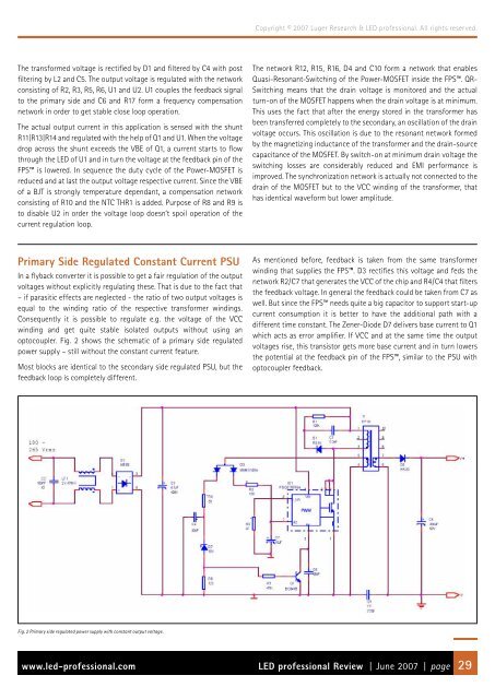
optocoupler. Fig. 2 shows the schematic of a primary side regulated<br />
power supply – still without the constant current feature.<br />
Most blocks are identical to the secondary side regulated PSU, but the<br />
feedback loop is completely different.<br />
Fig. 2 Primary side regulated power supply with constant output voltage.<br />
Copyright © 2007 Luger Research & <strong>LED</strong> professional. All rights reserved.<br />
The network R12, R15, R16, D4 and C10 form a network that enables<br />
Quasi-Resonant-Switching of the Power-MOSFET inside the FPS. QR-<br />
Switching means that the drain voltage is monitored and the actual<br />
turn-on of the MOSFET happens when the drain voltage is at minimum.<br />
This uses the fact that after the energy stored in the transformer has<br />
been transferred completely to the secondary, an oscillation of the drain<br />
voltage occurs. This oscillation is due to the resonant network formed<br />
by the magnetizing inductance of the transformer and the drain-source<br />
capacitance of the MOSFET. By switch-on at minimum drain voltage the<br />
switching losses are considerably reduced and EMI performance is<br />
improved. The synchronization network is actually not connected to the<br />
drain of the MOSFET but to the VCC winding of the transformer, that<br />
has identical waveform but lower amplitude.<br />
As mentioned before, feedback is taken from the same transformer<br />
winding that supplies the FPS. D3 rectifies this voltage and feds the<br />
network R2/C7 that generates the VCC of the chip and R4/C4 that filters<br />
the feedback voltage. In general the feedback could be taken from C7 as<br />
well. But since the FPS needs quite a big capacitor to support start-up<br />
current consumption it is better to have the additional path with a<br />
different time constant. The Zener-Diode D7 delivers base current to Q1<br />
which acts as error amplifier. If VCC and at the same time the output<br />
voltages rise, this transistor gets more base current and in turn lowers<br />
the potential at the feedback pin of the FPS, similar to the PSU with<br />
optocoupler feedback.<br />
www.led-professional.com <strong>LED</strong> professional Review | June 2007 | page 29