LED drivers Phosphor technology - Beriled
LED drivers Phosphor technology - Beriled
LED drivers Phosphor technology - Beriled

You also want an ePaper? Increase the reach of your titles
YUMPU automatically turns print PDFs into web optimized ePapers that Google loves.
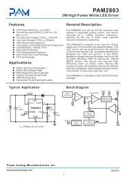
Next Generation MR16<br />
<strong>LED</strong> Lamps Powered by the<br />
MAX16820 Driver IC<br />
> Da Feng Weng, Product Definer, and Mehmet Nalbant,<br />
Director, Application Engineering Maxim Integrated Products<br />
Inc., Sunnyvale, Calif.<br />
Halogen MR16 lamps are widely used in professional store and home<br />
decorative lighting applications. The power dissipation of the most<br />
commonly used halogen based MR16s ranges from 10W to 50W and<br />
their light output ranges from 150 to 800 lumens. That equates to an<br />
efficacy of about 15lm/W. The life time of a typical halogen bulb is<br />
limited to about 2000hrs. In addition the filament should not be exposed<br />
to high levels of vibration to prevent the bulb from failing prematurely.<br />
Today’s <strong>LED</strong> technologies offer a cost effective alternative. For example<br />
the latest generation of 5W (one chip 4x4mm package) and 10W (four<br />
chip 7x7mm package) high power <strong>LED</strong>s from LedEngin generate typical<br />
efficacies of 45lm/W@1000mA/Tj=120’C. That equates to typical<br />
lumen output levels of 155lm (@1000mA/Tj=120’C) for the 5W package<br />
and 345lm (@700mA/Tj=120’C) for the 10W package in actual use<br />
conditions. It can be shown that when these <strong>LED</strong>s perform at the same<br />
brightness level as halogen bulbs, that then the power dissipation can<br />
be reduced by about 50%. In addition LedEngin predicts a remarkable<br />
lumen maintenance of 90% @100k hrs/Tj=120’C thus eliminating the<br />
need for bulb replacement throughout the life of the product.<br />
For the MR16 reference design Maxim selected the LedEngin 5W product<br />
to demonstrate the 1000mA drive capabilities of the MAX16820 IC<br />
circuit. In most MR16 applications, the input voltage is 12VAC±10%.<br />
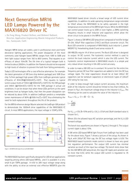
Figure 1. 5W MR16 <strong>LED</strong> Lamp Circuit with MAX16820<br />
The MAX16820 has been specifically designed for <strong>LED</strong> driver applications<br />
targeting among others <strong>LED</strong> based MR16s, and it is available in a very<br />
small 6-pin TDFN package. A 4.5V to 28V input voltage range along<br />
with the ability to drive an external cost effective MOSFETs give the<br />
Copyright © 2007 Luger Research & <strong>LED</strong> professional. All rights reserved.<br />
MAX16820 based driver circuits a broad range of <strong>LED</strong> current drive<br />
capabilities. In addition its wide operating temperature range extended<br />
to 125oC allows the MAX16820 to be safely operated in the high<br />
temperature environment of the MR16 light fixture. While the MAX16820<br />
can control power levels up to 25W or even higher, a 2MHz switching<br />
frequency results in small inductor and capacitors which allow the<br />
driver circuit to be placed in the MR16 fixture.<br />
Figure 1, shows a 5W MR16 <strong>LED</strong> lamp driver composed of rectifier bridge<br />
D1~D4, 100uF filter capacitors C1&C2 and Buck converter circuit. The<br />
Buck <strong>LED</strong> converter is composed of MAX16820, buck inductor L, power<br />
MOSFET Q, freewheeling diode D and sense resistor R.<br />
5W HB<strong>LED</strong>s require 1A of drive current. The Buck <strong>LED</strong> driver is designed<br />
to output 1A DC current. The hysteretic control method is used to<br />
control the buck inductor current which is also the <strong>LED</strong> current. The<br />
hysteretic control implemented in MAX16820 results in a simple and<br />
very robust driver resulting in 5% <strong>LED</strong> current accuracy.<br />
In order to make a 5W <strong>LED</strong> run in constant 1A current for the entire line<br />
frequency period, DC bus filter capacitors are added to limit the DC bus<br />
voltage ripple. The total capacitance should be at least 200uf. DC<br />
capacitors can be tantalum capacitors or electrolytic types of 220uF/<br />
25V rating for low cost.<br />
In order to keep enough high output current accuracy, the maximum<br />
di/dt of the inductor current should be limited to less than 0.4A/us. As<br />
shown in Fig.1, the maximum voltage drop on the inductor is VLMAX. The<br />
following can be used to calculate the value of the inductor L:<br />
VLMAX = VAC_IN · (1 + δ) · √2 - VO<br />
L = V LMAX<br />
di/dt<br />
For VAC_IN=12V, δ=10% and VO=3.6, L>37uH and 39uH standard value is<br />
chosen for L.<br />
Where: δ is the allowed input AC variation percentage, and the VO is <strong>LED</strong><br />
forward voltage.<br />
The bench test waveforms are shown in Figures 2 through 5. The output<br />
current ripple is about 10%.<br />
A 5W white <strong>LED</strong> based MR16 light fixture from LedEngin has been used<br />
for the above tests, Figure 7 shows a picture of the setup. As shown in<br />
Fig.4, with 200uF DC filter cap, the DC bus voltage ripple is 8.5V. The<br />
MAX16820 based hysteretic mode control is shown to have very good<br />
line regulation performance. The output <strong>LED</strong> current has minimal<br />
variation as result of the input bus voltage. The bench tests show that<br />
for the 5W MR16 <strong>LED</strong> lamp driver, the input AC ripple and variation can<br />
be more that 8.5V, while the output <strong>LED</strong> current is regulated to 1A<br />
constant current.<br />
www.led-professional.com <strong>LED</strong> professional Review | June 2007 | page 32