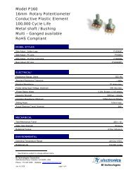
LED drivers Phosphor technology - Beriled
LED drivers Phosphor technology - Beriled
LED drivers Phosphor technology - Beriled

You also want an ePaper? Increase the reach of your titles
YUMPU automatically turns print PDFs into web optimized ePapers that Google loves.
<strong>LED</strong> is manufactured on a chip like other semiconductor devices. This is<br />
then fixed to a heat slug that penetrates through the package, and the<br />
connections are made to external terminals by bonding wires. The slug<br />
is then encapsulated with a silicone gel and covered with a hard plastic<br />
lens that is coated with a phosphor. This avoids stress on the bonding<br />
wires. An epoxy lens would not be practicable, because of thermal<br />
expansion.<br />
Heat is the biggest enemy of power <strong>LED</strong>s. A major advantage of the<br />
power <strong>LED</strong> is lifetime, which can exceed 50,000 hours. In comparison, a<br />
typical fluorescent lamp has a lifetime of 8,000 hours and a typical<br />
incandescent bulb has a lifetime of 2,000 hours. To achieve this long<br />
lifetime, the junction temperature of the <strong>LED</strong> must be kept low. The<br />
actual temperature limit is a subject of debate among the major <strong>LED</strong><br />
manufacturers, but in general, the junction temperature must be kept at<br />
80 degrees Celsius or less to achieve a long lifetime. When run<br />
continuously above this temperature, the <strong>LED</strong> can fail in less than<br />
10,000 hours. At temperatures near 80 degrees, the light output will fall<br />
off rapidly in the first 10,000 hours, but the <strong>LED</strong> will continue to generate<br />
a reduced light output for long after that. At more moderate temperature<br />
levels, the <strong>LED</strong> will produce a relatively consistent light output over its<br />
lifetime.<br />
Although <strong>LED</strong>s have evolved to be very efficient sources of light, every<br />
design is a trade-off between light output, efficacy and heat-sink<br />
design. It may be necessary to drive a power <strong>LED</strong> at a reduced power<br />
level to meet temperature and heat-sink design requirements.<br />
Furthermore, the packaging requirements of the lighting fixture can<br />
limit the ability to provide good heat sinking.<br />
Power <strong>LED</strong>s with power levels exceeding 3W have become widely<br />
available. However, it is still easier to meet thermal design requirements<br />
using multiple smaller <strong>LED</strong>s in the 1-2W power range. Greater efficacy<br />
can be obtained when the <strong>LED</strong> is driven at a lower current. <strong>LED</strong> systems<br />
will become easier to design as the efficacy of <strong>LED</strong>s increases.<br />
The <strong>LED</strong> requires a source of constant current, rather than constant<br />
voltage. For indicator and lower-power types, a resistor will be adequate.<br />
For <strong>LED</strong>s above 1W, this becomes impractical. Standard switch-mode<br />
power supply (SMPS) topologies and controllers can be used to drive<br />
the <strong>LED</strong> at these higher power levels, using <strong>LED</strong> current as the feedback<br />
to the controller instead of voltage. The choice of topology depends on<br />
the system input voltage, <strong>LED</strong> forward voltage and the number of <strong>LED</strong>s<br />
connected in series.<br />
It is also important to consider how current is drawn from the AC line. A<br />
typical bridge rectifier circuit with filter capacitors will only consume<br />
current from the AC line at the peaks of the AC input voltage. The result<br />
is a current waveform with high harmonic content and a poor power<br />
factor. An active PFC circuit can improve the conversion of AC power to<br />
DC power, by forcing the current consumption of the circuit to track the<br />
envelope of the incoming AC line voltage. Power factor correction helps<br />
to meet energy-efficiency requirements and helps customers to achieve<br />
a faster payback for electronic lighting controls.<br />
Copyright © 2007 Luger Research & <strong>LED</strong> professional. All rights reserved.<br />
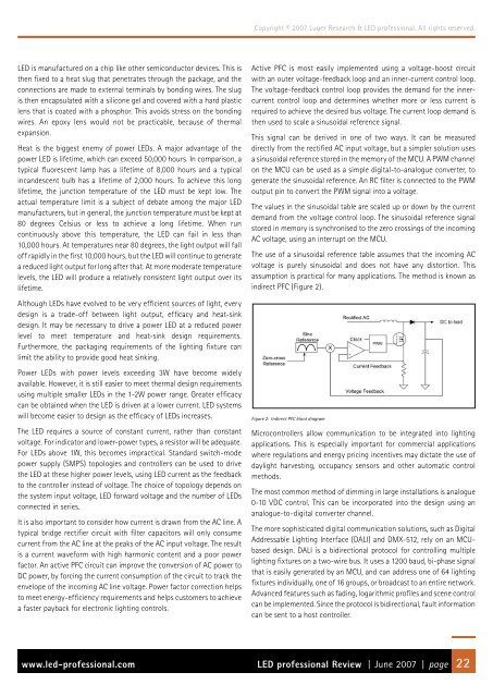
Active PFC is most easily implemented using a voltage-boost circuit<br />
with an outer voltage-feedback loop and an inner-current control loop.<br />
The voltage-feedback control loop provides the demand for the innercurrent<br />
control loop and determines whether more or less current is<br />
required to achieve the desired bus voltage. The current loop demand is<br />
then used to scale a sinusoidal reference signal.<br />
This signal can be derived in one of two ways. It can be measured<br />
directly from the rectified AC input voltage, but a simpler solution uses<br />
a sinusoidal reference stored in the memory of the MCU. A PWM channel<br />
on the MCU can be used as a simple digital-to-analogue converter, to<br />
generate the sinusoidal reference. An RC filter is connected to the PWM<br />
output pin to convert the PWM signal into a voltage.<br />
The values in the sinusoidal table are scaled up or down by the current<br />
demand from the voltage control loop. The sinusoidal reference signal<br />
stored in memory is synchronised to the zero crossings of the incoming<br />
AC voltage, using an interrupt on the MCU.<br />
The use of a sinusoidal reference table assumes that the incoming AC<br />
voltage is purely sinusoidal and does not have any distortion. This<br />
assumption is practical for many applications. The method is known as<br />
indirect PFC (Figure 2).<br />
Figure 2: Indirect PFC block diagram<br />
Microcontrollers allow communication to be integrated into lighting<br />
applications. This is especially important for commercial applications<br />
where regulations and energy pricing incentives may dictate the use of<br />
daylight harvesting, occupancy sensors and other automatic control<br />
methods.<br />
The most common method of dimming in large installations is analogue<br />
0-10 VDC control. This can be incorporated into the design using an<br />
analogue-to-digital converter channel.<br />
The more sophisticated digital communication solutions, such as Digital<br />
Addressable Lighting Interface (DALI) and DMX-512, rely on an MCUbased<br />
design. DALI is a bidirectional protocol for controlling multiple<br />
lighting fixtures on a two-wire bus. It uses a 1200 baud, bi-phase signal<br />
that is easily generated by an MCU, and can address one of 64 lighting<br />
fixtures individually, one of 16 groups, or broadcast to an entire network.<br />
Advanced features such as fading, logarithmic profiles and scene control<br />
can be implemented. Since the protocol is bidirectional, fault information<br />
can be sent to a host controller.<br />
www.led-professional.com <strong>LED</strong> professional Review | June 2007 | page 22