Betriebsanleitung Sicherheitsschalter TP...AS2 - EUCHNER GmbH ...
Betriebsanleitung Sicherheitsschalter TP...AS2 - EUCHNER GmbH ...
Betriebsanleitung Sicherheitsschalter TP...AS2 - EUCHNER GmbH ...

Create successful ePaper yourself
Turn your PDF publications into a flip-book with our unique Google optimized e-Paper software.
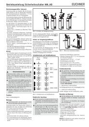
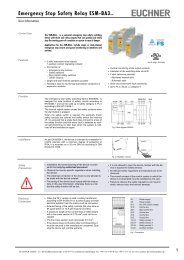
<strong>Betriebsanleitung</strong> <strong>Sicherheitsschalter</strong> <strong>TP</strong>...<strong>AS2</strong>Elektrischer AnschlussFür den Einsatz und die Verwendung gemäß denAnforderungen von (UL) muss ein Trenntransformatoroder eine Spannungsversorgung mitsekundärem Überstromschutz (3 A) verwendetwerden.Der Anschluss des <strong>Sicherheitsschalter</strong>s an das Bussystemerfolgt mit einem 4-poligen Anschlusskabelmit M12-Steckverbinder über eine passive AS-InterfaceVerteilerbox mit gelbem und schwarzemAS-Interface Kabel.1 AS-Interface +2 Hilfsspannung 0 V3 AS-Interface -4 Hilfsspannung 24 VBild 2: Anschlussbelegung M12-SteckverbinderInbetriebnahmeAnsicht Steckverbinder<strong>Sicherheitsschalter</strong>4 31 2 Einstellen der AS-Interface AdresseDas Einstellen der Adresse ist vor oder nach derMontage möglich.Die AS-Interface Adresse des <strong>Sicherheitsschalter</strong>swird mit einem AS-Interface Programmiergerät eingestellt.Adresse 1 bis 31 ist gültig.Dazu wird das Programmiergerät mit einemProgrammierkabel an den M12-Steckverbinder des<strong>Sicherheitsschalter</strong>s angeschlossen.Auslieferungszustand ist die Adresse 0 (im Betriebleuchtet die AS-Interface LED Fault !). Konfiguration im AS-Interface Sicherheitsmonitor(siehe <strong>Betriebsanleitung</strong> AS-Interface Sicherheitsmonitorund Zustandstabelle)Der <strong>Sicherheitsschalter</strong> wird im AS-InterfaceSicherheitsmonitor mit der eingestellten AS-InterfaceAdresse z.B. wie folgt konfiguriert: zweikanalig abhängig mit Anlauftestung Synchronisationszeit = typ. 3 sIn dieser Betriebsart ist zur Durchführung der Anlauftestungvor jedem Wiederanlauf das Öffnen derSchutzeinrichtung erforderlich.Auf die Anlauftestung kann auch verzichtet werden. Das Abschalten des Zuhaltemagneten durch denMonitor allein ist nicht möglich.Die Steuerung (SPS) muss deshalb über denAS-Interface Ausgang D0 = 0 den Zuhaltemagnetin die Sperrstellung abschalten, um die Einschaltbedingungenfür den ersten Freigabekreis wiederherzustellen. Meldesignale (nicht sicherheitsrelevant)Der Zustand der Türmeldekontakte SK kann auchdurch die Steuerung (SPS) abgefragt werden (siehe<strong>Betriebsanleitung</strong> AS-Interface Sicherheitsmonitor). LED-AnzeigenDer AS-Interface Buszustand wird über zwei LEDs(Power, Fault) angezeigt.Zwei zusätzliche LEDs können über den AS-InterfaceBus, z.B. zur Anzeige der Meldesignale, geschaltetwerden (siehe Meldesignale und technische Daten).FunktionskontrolleWarnung! Tödliche Verletzung durch Fehler beider Installation und Funktionskontrolle.Stellen Sie vor der Funktionskontrolle sicher, dasssich keine Personen im Gefahrenbereich befinden.Beachten Sie die geltenden Vorschriften zurUnfallverhütung.Nach der Installation und jedem Fehler muss einevollständige Kontrolle der Sicherheitsfunktion durchgeführtwerden. Gehen Sie dabei folgendermaßen vor: Mechanische FunktionsprüfungDer Betätiger muss sich leicht in den Betätigungskopfeinführen lassen. Zur Überprüfung Schutzeinrichtungmehrmals schließen. Elektrische Funktionsprüfung1. Betriebsspannung einschalten.2. Alle Schutzeinrichtungen schließen.Bei Zuhaltung durch Magnetkraft Zuhaltungaktivieren. Die Maschine darf nicht selbständig anlaufen. Die Schutzeinrichtung darf sich nicht öffnen lassen.3. Betrieb in der Steuerung freigeben. Die Zuhaltung darf sich nicht deaktivieren lassen,solange der Betrieb freigegeben ist.4. Betrieb in der Steuerung abschalten und Zuhaltungdeaktivieren. Die Schutzeinrichtung muss so lange zugehaltenbleiben, bis kein Verletzungsrisiko mehr besteht. Die Maschine darf sich nicht starten lassen, solangedie Zuhaltung deaktiviert ist.Wiederholen Sie die Schritte 2 - 4 für jede Schutzeinrichtungeinzeln.Kontrolle und WartungBei Beschädigung oder Verschleiß muss der gesamteSchalter mit Betätiger ausgetauscht werden.Der Austausch von Einzelteilen oder Baugruppen,insbesondere des Betätigungskopfes, istunzulässig!Hinweis: Das Baujahr ist in der unteren, rechten Eckedes Typenschilds ersichtlich.Wartungsarbeiten sind nicht erforderlich. Um eineeinwandfreie und dauerhafte Funktion zu gewährleisten,sind regelmäßige Kontrollen erforderlich auf einwandfreie Schaltfunktion sichere Befestigung der Bauteile Ablagerungen und Verschleiß gelockerte Steckverbinder.Haftungsausschluss bei nicht bestimmungsgemäßem Gebrauch Nichteinhalten der Sicherheitshinweise Anbau und elektrischem Anschluss durch nicht autorisiertesFachpersonal nicht durchgeführten Funktionskontrollen.EG-KonformitätserklärungDer nachstehende Hersteller erklärt hiermit, dass dasProdukt in Übereinstimmung ist mit den Bestimmungender nachfolgend aufgeführten Richtlinie(n) unddass die jeweiligen Normen zur Anwendung gelangtsind.<strong>EUCHNER</strong> <strong>GmbH</strong> + Co. KGKohlhammerstraße 1670771 Leinfelden-Echterdingen, DeutschlandAngewendete Richtlinien: Maschinenrichtlinie 2006/42/EGAngewendete Normen: EN 60947-5-1:2004 + Cor.:2005 + A1:2009 EN 1088:1995+A2:2008Leinfelden, Juli 2010Dipl.-Ing. Michael EuchnerGeschäftsführerDuc Binh NguyenDokumentationsbevollmächtigterDie unterzeichnete EG-Konformitätserklärung ist demProdukt beigelegt.Technische DatenParameterGehäusewerkstoffSchutzart nach IEC 529Mech. LebensdauerUmgebungstemperaturEinbaulageAnfahrgeschwindigkeit max.BetätigungskraftAuszugskraftRückhaltekraftZuhaltekraft F maxZuhaltekraft F Zhnach Prüfgrundsatz GS-ET-19MasseSchaltprinzip SK, ÜKEMV-SchutzanforderungenWertGlasfaserverstärkterThermoplastIP 67, Gegenstecker gesteckt1x10 6 Schaltspiele-20...+55°Cbeliebig20 m/min10 N20 N10 N1300 Nca. 0,5 kgZwangsöffner, Schleichschaltgliedgemäß EN 50295 (AS-InterfaceNorm) und IEC 62026ZuhaltemagnetMagnetbetriebsspannung DC 24 V +10%/-15% 8 W(Hilfsspannung auf schwarzer Netzgerät mit sicherer TrennungAS-Interface Leitung) (IEC 60742, PELV)Magnetbetriebsstrom 300 mAEinschaltdauer ED 100 %AnschlussartM12-SteckverbinderMindestweg und NachlaufAnfahrrichtung Betätiger BetätigerStandardNachlaufhorizontal (h) 28 + 2 28+7vertikal (v) 29,5 + 1,5 –AS-Interface Daten gemäß EA-Code: 7AS-Interface Spezifikation 2.1 ID-Code: BGesamtstromaufnahme max. 45 mAGültige AS-Interface Adressen 1 - 31AS-Interface Eingänge nach AS-Interface Safety at WorkTürüberwachungskontakte SK D0, D1, D2, D3AS-Interface AusgängeD0Zuhaltemagnet, 1 = Magnet bestromtD1LED rot, 1 = LED einD2LED grün, 1 = LED einAS-Interface LED Power grün, AS-Interface Spannung liegt anAS-Interface LED Fault rot, Offline Phase oder Adresse 0Zuverlässigkeitswerte nach EN ISO 13849-1B10d 3 x 10 6(F Zh= F max) = 1000 N1,3Technische Änderungen vorbehalten, alle Angaben ohne Gewähr. © <strong>EUCHNER</strong> <strong>GmbH</strong> + Co. KG 093722-05-10/11 (Originalbetriebsanleitung)<strong>EUCHNER</strong> <strong>GmbH</strong> + Co. KG Kohlhammerstraße 16 D-70771 Leinfelden-Echterdingen Tel. +49/711/75 97-0 Fax +49/711/75 33 16 www.euchner.de info@euchner.de
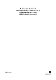
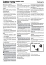
<strong>Betriebsanleitung</strong> <strong>Sicherheitsschalter</strong> <strong>TP</strong>...<strong>AS2</strong>Radiusbetätiger P-OU / P-OUN31hR > 90v3,53543192M20x1,5 (2x)144GN RDPower Faultfür M5 > 35 mmISO 1207 (DIN84)ISO 4762(DIN 912)M = 1,5 NmHilfsentriegelungM = 0,5 NmSicherungsschraube261228 +22035Radiusbetätiger P-LR / P-LRN22R > 1001416304240M = 0,6 Nm163,58,5Betätiger-TypTürradius min. [mm]Betaetiger-P-G... 1000Betaetiger-P-W... 1000RADIUSBETAETIGER-P-OU... 90RADIUSBETAETIGER-P-LR... 100Bild 3: MaßzeichnungenBild 4: Minimale TürradienZustandstabelleProgrammierung Zustand D0, D1 D2, D3 MonitordiagnoseSchutzeinrichtung geschlossen, Codefolge GrünZuhaltung aktiv oder nicht aktiv.Zwischenzustand beim Öffnen oder Schließen2-kanaligder Schutzeinrichtung. Halbfolge 00 Beim Öffnen: Gelb blinkendabhängigSchalter S1 (intern) offenBeim Schließen: RotSynchronisationszeitZwischenzustand beim Öffnen oder SchließenNach Ablauf der Synchronisationszeit:3 sder Schutzeinrichtung. 00 Halbfolge Gelb blinkendSchalter S2 (intern) offenSchutzeinrichtung offen 00 00 RotAdresse 0 oder Kommunikation gestört – Grau
Operating Instructions Safety Switches <strong>TP</strong>...<strong>AS2</strong>Correct use<strong>EUCHNER</strong> safety switches series <strong>TP</strong>...<strong>AS2</strong> areoperated as a slave on the safety bus AS-InterfaceSafety at Work and function as electromagnetic interlockdevices with guard locking without guard lockmonitoring.In combination with a safety guard and the machinecontrol, this safety component prevents the safetyguard from being opened while a dangerous machinemovement is being performed.For the control system, this means that starting commands which cause hazardoussituations must become active only when the safetyguard is in the protective position.The locked position of the guard locking must bereleased only when the hazardous situation is nolonger present.Before safety switches are used, a risk assessmentmust be performed on the machine, e.g., inaccordance with EN ISO 13849, Safety of machinery - Safety-relatedparts of control systems EN 12100-1, Safety of machinery - Generalprinciples for design - Risk assessment and riskreduction IEC 62061, Safety of machinery. Functional safetyof safety-related electrical, electronic andprogrammable electronic control systems.Correct use includes compliance with the relevantrequirements for installation and operation, particularly EN ISO 13849, Safety of machinery - Safety-relatedparts of control systems EN 1088, Safety of machinery. Interlocking devicesassociated with guards. Principles for design andselection EN 60 204-1, Electrical equipment of machines.Important: The user is responsible for safe integration of thedevice in a safe overall system. For this purpose,the overall system must be validated, e.g. inaccordance with EN ISO 13849-2. If the simplified method according to section 6.3EN ISO 13849-1:2008 is used for validation, thePerformance Level (PL) may be reduced if severaldevices are connected one after the other. If a product data sheet is included with the product,the information on the data sheet applies in case ofdiscrepancies with the operating instructions.Safety precautionsSafety switches fulfill a personal protection function.Incorrect installation or tampering can lead to severeinjuries to personnel.Safety components must not be bypassed(bridging of contacts), turned away, removed orotherwise rendered ineffective.On this topic pay attention in particular to themeasures for reducing the possibility of bypassingaccording to EN 1088:1995.A2:2008, sec. 5.7.The switching operation may only be triggeredby actuators specially provided for this purposewhich are permanently connected to theprotective guard.A complete safety-oriented system generallyconsists of several signaling devices, sensors,evaluation units and concepts for safe shutdown.The manufacturer of a machine or installation isresponsible for correct and safe overall function.All safety instructions and requirements statedin the Operating Instructions of the AS-Interfacesafety monitor used must be observed.Mounting, electrical connection and setup onlyby authorized personnel.Function<strong>EUCHNER</strong> safety switches series <strong>TP</strong>...AS feature aslave connection to the safety bus AS-Interface Safetyat Work. They permit locking of movable safetyguards.The position monitoring of the safety guard is carriedout with two switching contacts (door monitoringcontact SK).When the safety guard is closed, each <strong>TP</strong>...AStransmits a switch-specific, unique safety codesequence with 8 x 4 bits via the AS-Interface. Thiscode sequence is evaluated by an AS-Interface safetymonitor. The first positively driven contact SK for dooropening is represented by the AS-Interface input bitsD0 and D1.The second positively driven contact SK isrepresented by the AS-Interface input bits D2 andD3.The safety switch must be correspondingly configuredin the AS-Interface safety monitor (refer to theoperating instructions of the AS-Interface safetymonitor used and the status table).Version <strong>TP</strong>3...<strong>AS2</strong>(guard locking by spring force)For the purpose of the protection of peopleagainst dangerous over-traveling movements, itis also necessary to switch the black AS-Interfacecable (auxiliary power), which is connectedto the AS-Interface distribution box and theswitch, via a standstill monitor or via the safeswitch-on delay feature in a dual-channel AS-Interfacesafety monitor (e.g. door locking forduration of the delay time).The guard locking pin is held in the locked position byspring force and unlocked by electromagneticactuation. The spring interlock guard locking functionsin accordance with the closed-circuit current principle.The safety guard cannot be opened immediately inthe event of interruption of the solenoid power supply.For the purpose of process protection, the guardlocking solenoid can be switched via the software bymeans of AS-Interface output bit D0.Version <strong>TP</strong>4...<strong>AS2</strong>(guard locking by solenoid force)This type must be used only in special casesafter strict assessment of the accident risk!The safety guard can be opened immediately inthe event of interruption of the solenoid powersupply!The guard locking pin is held in the locked position byelectromagnetic force and released by spring force.The guard locking operates in accordance with theopen-circuit current principle.For the purpose of process protection, the guardlocking solenoid can be switched via the software bymeans of AS-Interface output bit D0.Door monitoring contact SK is positively opened andguard locking is blocked in this position when theactuator is removed (protection against unintentionalclosing). The values 0, 0, 0, 0 are continuously sentvia AS-Interface input bits D0 to D3.<strong>TP</strong>4...AS: The guard locking is deactivated when thesolenoid operating voltage is applied, and release isissued by means of AS-Interface output bit D0. Solenoidmonitoring contact ÜK is opened. The value pair0, 0 is sent during each bus cycle via AS-Interfaceinput bits D2 and D3.The actuator can be removed.Door monitoring contact SK is positively opened andguard locking is blocked in this position when theactuator is removed (protection against unintentionalclosing). The values 0, 0, 0, 0 are continuously sentvia AS-Interface input bits D0 to D3.Mechanical releaseIn the event of malfunctions, the guard locking can bereleased with the mechanical release irrespective ofthe state of the solenoid (see Figure 3). Unscrew locking screw. Using a screwdriver, turn the mechanical releaseby approx. 180° in the direction of the arrow.The locking screw must be returned to its originalposition and sealed after use (for example with sealinglacquer).MountingSafety switches and actuators must not be usedas an end stop.Mount the safety switch only in assembledcondition!Increased overtravel of the actuator is notpossible with vertical approach direction.Assemble the safety switch so that access to the switch is difficult for operatingpersonnel when the safety guard is open operation of the mechanical release is still possible address programming, inspection and replace-mentby authorized personnel is possible. Insert the actuator in the actuating head. Mount the safety switch positively. Permanently connect the actuator to the safetyguard so that it cannot be detached, e.g. using theenclosed non-removable screws, rivets or welding. Fit an additional stop for the movable part of thesafety guard.Changing the actuating direction Closing safety guard and activating guard lockingThe guard locking pin is released by insertion of theactuator into the safety switch.<strong>TP</strong>3...AS: The guard locking pin is moved to lockedposition by spring force.Figure 1: Changing the actuating direction<strong>TP</strong>4...AS: The guard locking pin is moved to locked Insert the actuator in the actuating head.position when the solenoid operating voltage isapplied.Remove the screws from the actuating head.The safety contacts are closed.The complete safety code sequence (8 x 4 bits) issent via AS-Interface input bits D0 to D3. Set the required direction. Tighten the screws with a torque of 0.6 Nm. Cover the unused actuating slots with the enclosed Deactivating guard locking, opening safety guardslot covers.<strong>TP</strong>3...AS: The guard locking is deactivated when thesolenoid operating voltage is applied, and release isissued by means of AS-Interface output bit D0. Solenoidmonitoring contact ÜK is opened. The value pair0, 0 is sent during each bus cycle via AS-Interfaceinput bits D2 and D3.The actuator can be removed.Protection against environmental influencesA lasting and correct safety function requires that theactuating head must be protected against thepenetration of foreign bodies such as swarf, sand,blasting shot, etc.Cover the actuating slot, the actuator and the ratingplate during painting work!
Operating Instructions Safety Switches <strong>TP</strong>...<strong>AS2</strong>Electrical connectionFor use and operation as per the requirements of(UL), an isolating transformer or a power supplywith secondary overcurrent protection (3 A) must beused.The safety switch is connected to the bus systemwith a 4-core connecting cable with M12 plugconnector via a passive AS-Interface distribution boxwith yellow and black AS-Interface cable.1 AS-Interface +2 Auxiliary voltage 0 V3 AS-Interface -4 Auxiliary voltage24 VView of safety switchplug connector4 31 2Fig. 2: Terminal assignment M12 plug connectorSetup Setting the AS-Interface addressThe address can be set prior to or after assembly.The AS-Interface address of the safety switch is setusing an AS-Interface programming device. Addresses1 to 31 are valid.The unit is programmed by connecting the programmingdevice to the M12 plug connector on the safetyswitch with an AS-Interface programming device.Address 0 is the default setting on delivery (the AS-Interface LED Fault! is lit during operation). Configuration in the AS-Interface safety monitor(see operating instructions for the AS-Interface safetymonitor and status table)The safety switch is configured in the AS-Interfacesafety monitor with the AS-Interface address set asfollows, for example: Two-channel dependent With start-up test Synchronization time = typ. 3 sIn this operating mode, the safety guard must beopened each time prior to restarting in order to performthe start-up test.It is possible to skip the start-up test. It is not possible to switch off the guard lockingsolenoid by means of the monitor alone.The control system (PLC) must therefore switch offthe guard locking solenoid in locked position viaAS-Interface output D0 = 0 in order to re-establishthe switch-on conditions for the first OSSD. Status signals (not relevant to safety)The state of the door monitoring contacts SK canalso be polled by the control system (PLC) (refer tothe operating instructions for the AS-Interface safetymonitor). LED indicatorsThe AS-Interface bus status is indicated by two LEDs(Power, Fault).Two additional LEDs can be connected via the AS-Interface bus, e.g. to indicate the status signals (seeStatus signals and Technical data).Functional checkWarning! Danger of fatal injury as a result of faultsin installation and functional check.Before carrying out the functional check, makesure that there are no persons in the dangerarea. Observe the valid accident preventionregulations.After installation and any fault, the safety function mustbe fully checked. Proceed as follows: Mechanical function testThe actuator must slide easily into the actuating head.Close the safety guard several times to check thefunction. Electrical function test1. Switch on operating voltage.2. Close all safety guards.Guard locking by solenoid force Activateguard locking. The machine must not start automatically. It must not be possible to open the safety guard.3. Enable operation in the control system. It must not be possible to deactivate the guardlocking as long as operation is enabled.4. Disable operation in the control system anddeactivate guard locking. The safety guard must remain locked until there isno longer any risk of injury. It must not be possible to start the machine as longas the guard locking is deactivated.Repeat steps 2 - 4 for each safety guard.Inspection and serviceIf damage or wear is found, the complete switchand actuator assembly must be replaced.Replacement of individual parts or assemblies,especially of the actuating head, is not permitted!Note: The year of manufacture can be seen in thebottom, right corner of the rating plate.No servicing is required, but regular inspection ofthe following is necessary to ensure trouble-free longtermoperation: correct switching function secure mounting of components dirt and wear loose plug connectors.Exclusion of liability under the followingcircumstances incorrect use non-compliance with safety regulations installation and electrical connection not performedby authorized personnel failure to perform functional checks.EC declaration of conformityThe manufacturer named below herewith declares thatthe product fulfills the provisions of the directive(s)listed below and that the related standards have beenapplied.<strong>EUCHNER</strong> <strong>GmbH</strong> + Co. KGKohlhammerstraße 1670771 Leinfelden-Echterdingen, GermanyDirectives applied: Machinery directive 2006/42/ECStandards applied: EN 60947-5-1:2004 + Cor.:2005 + A1:2009 EN 1088:1995+A2:2008Leinfelden, July 2010Dipl.-Ing. Michael EuchnerDirectorDuc Binh NguyenAuthorized representative empowered to draw updocumentationThe signed EC declaration of conformity is includedwith the product.Technical dataParametersHousing materialValueReinforcedthermoplasticDeg. of prot. acc. to IEC 529 IP 67, mating connector pluggedMechanical life1x10 6 operating cyclesAmbient temperature -20 ... +55°CInstallation position AnyApproach speed, max. 20 m/minActuating force10 NExtraction force20 NRetention force10 NLocking force F max1,300 NLocking force F Zh(Fin acc. with GS-ET-19Zh= F max) = 1000 N1,3WeightApprox. 0.5 kgSwitching principle SK, ÜK Positively driven, slow-actionswitching contactEMC protection requirements Acc. to EN 50295 (AS-Interfacestandard) and IEC 62026Interlocking solenoidSolenoid operating voltage DC 24 V +10%/-15% 8 W(auxiliary power on black Power supply unit with safe isolationAS-Interface line)(IEC 60742, PELV)Solenoid operating current 300 mADuty cycle 100%ConnectionM12 plug connectorMinimum travel and overtravelApproach direction Actuator ActuatorStandardOvertravelHorizontal (h) 28 + 2 28+7Vertical (v) 29.5 + 1.5 –AS-Interface data acc. to EA code: 7AS-Interface specification 2.1 ID code: BTotal current consumption, max. 45 mAValid AS-Interface addresses 1 - 31AS-Interface inputs Acc. to AS-Interface Safety at WorkDoor monitoring contacts SK D0, D1, D2, D3AS-Interface outputsD0Guard locking solenoid,1 = solenoid energizedD1Red LED, 1 = LED onD2Green LED, 1 = LED onAS-Interface LED Power Green, AS-Interface voltage presentAS-Interface LED Fault Red, offline phase or address 0Reliability values according to EN ISO 13849-1B10d 3 x 10 6Subject to technical modifications; no responsibility is accepted for the accuracy of this information. © <strong>EUCHNER</strong> <strong>GmbH</strong> + Co. KG 093722-05-10/11 (translation of the original operating instructions)<strong>EUCHNER</strong> <strong>GmbH</strong> + Co. KG Kohlhammerstraße 16 D-70771 Leinfelden-Echterdingen Tel. +49/711/75 97-0 Fax +49/711/75 33 16 www.euchner.de info@euchner.de
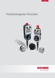
Operating Instructions Safety Switches <strong>TP</strong>...<strong>AS2</strong>Hinged actuator P-OU / P-OUN31hR > 90v3,53543192M20x1,5 (2x)144GN RDPower FaultFor M5 > 35 mmISO 1207 (DIN84)ISO 4762(DIN 912)M = 1.5 NmMechanicalreleaseM = 0.5 NmLocking screw261228 +22035Hinged actuator P-LR / P-LRN22R > 1001416304240M = 0.6 Nm163,58,5Actuator typeDoor radius min. [mm]Actuator P-G... 1,000Actuator P-W... 1,000HINGED ACTUATOR P-OU... 90HINGED ACTUATOR P-LR... 100Figure 3: Dimension drawingsFigure 4: Min. door radiiStatus tableProgramming State D0, D1 D2, D3 Monitor diagnosisSafety guard closed, Code sequence Greenguard locking active or not active.Intermediate state during opening or closing2-channelof the safety guard. Half-seq. 00 During opening: yellow flashingdependentSwitch S1 (internal) openDuring closing: redSynchronization timeIntermediate state during opening or closingAfter expiration of the synchronization time:3 sof the safety guard. 00 Half-seq. yellow flashingSwitch S2 (internal) openSafety guard open 00 00 RedAddress 0 or communication disrupted – Gray