Shell and Tube Heat Exchangers.pdf
Shell and Tube Heat Exchangers.pdf
Shell and Tube Heat Exchangers.pdf
Create successful ePaper yourself
Turn your PDF publications into a flip-book with our unique Google optimized e-Paper software.
Polaris<br />
Engineering<br />
St<strong>and</strong>ard<br />
SHELL AND TUBE HEAT EXCHANGERS<br />
610.1<br />
Rev.: 10<br />
Page: 1 of 30<br />
Date: 07/08/02<br />
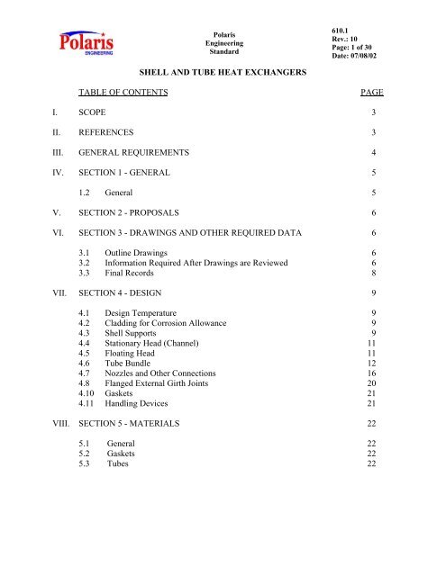
TABLE OF CONTENTS PAGE<br />
I. SCOPE 3<br />
II. REFERENCES 3<br />
III. GENERAL REQUIREMENTS 4<br />
IV. SECTION 1 - GENERAL 5<br />
1.2 General 5<br />
V. SECTION 2 - PROPOSALS 6<br />
VI. SECTION 3 - DRAWINGS AND OTHER REQUIRED DATA 6<br />
3.1 Outline Drawings 6<br />
3.2 Information Required After Drawings are Reviewed 6<br />
3.3 Final Records 8<br />
VII. SECTION 4 - DESIGN 9<br />
4.1 Design Temperature 9<br />
4.2 Cladding for Corrosion Allowance 9<br />
4.3 <strong>Shell</strong> Supports 9<br />
4.4 Stationary Head (Channel) 11<br />
4.5 Floating Head 11<br />
4.6 <strong>Tube</strong> Bundle 12<br />
4.7 Nozzles <strong>and</strong> Other Connections 16<br />
4.8 Flanged External Girth Joints 20<br />
4.10 Gaskets 21<br />
4.11 H<strong>and</strong>ling Devices 21<br />
VIII. SECTION 5 - MATERIALS 22<br />
5.1 General 22<br />
5.2 Gaskets 22<br />
5.3 <strong>Tube</strong>s 22
Polaris<br />
Engineering<br />
St<strong>and</strong>ard<br />
610.1<br />
Rev.: 10<br />
Page: 2 of 30<br />
TABLE OF CONTENTS PAGE<br />
IX. SECTION 6 - FABRICATION 23<br />
6.1 <strong>Shell</strong>s 23<br />
6.2 Pass Partition Plates 23<br />
6.3 Connection Junctions 23<br />
6.5 Welding 23<br />
6.6 <strong>Heat</strong> Treatment 23<br />
6.8 Gasket Contact Surfaces Other than Nozzle Flange Facings 24<br />
6.10 Assembly 24<br />
X. SECTION 7 - INSPECTION AND TESTING 25<br />
7.1 Quality Assurance 25<br />
7.2 Quality Control 25<br />
7.3 Pressure Testing 26<br />
7.4 Nameplates <strong>and</strong> Stamping 27<br />
XI. SECTION 8 - PREPARATION FOR SHIPMENT 27<br />
XII. SECTION 9 - SUPPLEMENTAL REQUIREMENTS 28<br />
APPENDIX I: SHELL & TUBE EXCHANGER ANCHOR LOCATION 29<br />
APPENDIX II: PREPARATION OF ROLLED JOINTS IN TUBESHEETS > 4" (thick) 30
I. SCOPE<br />
Polaris<br />
Engineering<br />
St<strong>and</strong>ard<br />
SHELL AND TUBE HEAT EXCHANGERS<br />
610.1<br />
Rev.: 10<br />
Page: 3 of 30<br />
A. This St<strong>and</strong>ard, together with applicable Industry St<strong>and</strong>ards, covers the minimum<br />
requirements for shell <strong>and</strong> tube exchangers used in general refinery <strong>and</strong><br />
petrochemical services.<br />
B. This St<strong>and</strong>ard does not cover double pipe exchangers, tank heaters, surface<br />
condensers (partially covered), <strong>and</strong> st<strong>and</strong>ard “off-the-shelf” accessory exchangers<br />
normally furnished with packaged equipment, such as small lube or seal flush<br />
coolers on rotating equipment.<br />
C. Where conflicts exist between this Engineering St<strong>and</strong>ard <strong>and</strong> other Polaris<br />
Engineering St<strong>and</strong>ards <strong>and</strong>/or applicable codes or regulations, the more stringent<br />
requirement shall govern. All conflicts shall be brought to client’s attention for<br />
resolution. client shall be the sole arbiter of any conflicts.<br />
II. REFERENCES<br />
This Polaris St<strong>and</strong>ard is to be used in conjunction with the latest revision of the st<strong>and</strong>ards<br />
<strong>and</strong> codes listed below, unless specifically noted. The terminology “latest revision” shall<br />
be interpreted as the revision in effect at the time of contract award. This Polaris<br />
St<strong>and</strong>ard may reference specific sections of some of these codes <strong>and</strong> st<strong>and</strong>ards. The<br />
revision of the codes <strong>and</strong> st<strong>and</strong>ards being referenced is noted below in parenthesis. This<br />
information is provided to identify the subject matter being referenced. Changes or<br />
exceptions made to the referenced code or st<strong>and</strong>ard shall apply to later revisions as<br />
applicable.<br />
A. American Petroleum Institute (API) St<strong>and</strong>ards<br />
660 <strong>Shell</strong>-<strong>and</strong>-<strong>Tube</strong> <strong>Heat</strong> <strong>Exchangers</strong> for General Refinery Services<br />
(6 th Edition, 2001)<br />
B. St<strong>and</strong>ards of the Tubular Exchanger Manufacturer's Association (TEMA) (8th<br />
Edition, 1999)<br />
C. Polaris Engineering St<strong>and</strong>ards<br />
1. 140.10 General Welding, Fabrication <strong>and</strong> Inspection<br />
2. 150.1 Equipment Purchases, General Engineering Requirements<br />
3. 170.1 Positive Material Identification (Alloy Materials)
Polaris<br />
Engineering<br />
St<strong>and</strong>ard<br />
4. 415.1 Design Loads for Structures <strong>and</strong> Equipment<br />
5. 500.1 Pressure Vessels - Carbon <strong>and</strong> Low Alloy Steel<br />
6. 500.2 Pressure Vessels - Alloy Lined Steel<br />
610.1<br />
Rev.: 10<br />
Page: 4 of 30<br />
7. 592.2.2 St<strong>and</strong>ard Nozzle Details for Clad <strong>and</strong> Lined Vessels<br />
8. 592.2.1 Nameplate Bracket Details<br />
9. 596.1.7 Grounding Lug Details<br />
10. 1400.1 Painting Process Equipment <strong>and</strong> Piping<br />
11. 1500.2 Hydraulic Stud Torquing<br />
D. American Society of Mechanical Engineers (ASME) St<strong>and</strong>ards:<br />
1. B16.5 Pipe Flanges <strong>and</strong> Flanged Fittings NPS ½ through NPS 24<br />
(1998)<br />
2. B16.20 Metallic Gaskets for Pipe Flanges, Ring-Joint, Spiral-<br />
Wound <strong>and</strong> Jacketed (2000)<br />
3. B16.47 Large Diameter Steel Flanges NPS 26 through NPS 60<br />
(1998)<br />
4. B46.1 Surface Texture (1995)<br />
5. Section I Rules for Construction of Power Boilers (2001)<br />
6. Section VIII Division 1 Rules for Construction of Pressure Vessels<br />
(2001)<br />
III. GENERAL REQUIREMENTS<br />
A. <strong>Shell</strong> <strong>and</strong> tube heat exchangers covered by this St<strong>and</strong>ard shall be designed,<br />
fabricated, inspected <strong>and</strong> tested in accordance with API St<strong>and</strong>ard 660 except as<br />
modified in this St<strong>and</strong>ard, the Polaris Engineering St<strong>and</strong>ards <strong>and</strong> individual data<br />
sheets listing specific operating conditions <strong>and</strong> special requirements, <strong>and</strong> TEMA.<br />
The order of precedence is:<br />
1. Data Sheet<br />
2. This St<strong>and</strong>ard<br />
3. Polaris Engineering St<strong>and</strong>ards<br />
4. API St<strong>and</strong>ard 660<br />
5. TEMA R<br />
B. Paragraph numbers referenced in this st<strong>and</strong>ard refer to paragraph numbers
Polaris<br />
Engineering<br />
St<strong>and</strong>ard<br />
610.1<br />
Rev.: 10<br />
Page: 5 of 30<br />
in API St<strong>and</strong>ard 660. Reference is made only to those paragraphs where<br />
an exception is taken, an option exercised, or supplementary information<br />
is added. Each paragraph is identified by the heading shown below which<br />
denotes what action has been taken regarding the subject matter of the<br />
corresponding paragraph of API St<strong>and</strong>ard 660.<br />
HEADING ACTION<br />
Decision A decision has been made where required by the<br />
corresponding paragraph.<br />
Exception An exception has been made to the corresponding<br />
paragraph. Such exception does not invalidate the entire<br />
subparagraph, but only that portion of the paragraph to<br />
which the exception applies.<br />
Substitution A substitution has been made for the corresponding<br />
paragraph in its entirety.<br />
Modification An amplification, rewording, or addition has been made to<br />
the corresponding paragraph, but not a substitution<br />
invalidating the paragraph.<br />
New A new subparagraph, which does not appear in API<br />
St<strong>and</strong>ard 660, which is to be inserted in numerical order in<br />
API St<strong>and</strong>ard 660 adding supplemental requirements to the<br />
same main paragraph subject matter.<br />
Deletion A statement that is to be completely removed from the<br />
st<strong>and</strong>ard.<br />
IV. SECTION 1 - GENERAL<br />
1.2 General<br />
1.2.1 Modification - <strong>Exchangers</strong> shall conform to Class R requirements, of the<br />
TEMA St<strong>and</strong>ards (latest edition <strong>and</strong> addenda). In addition ASME Section<br />
I of the ASME Code may be m<strong>and</strong>ated in lieu of Section VIII, Division I<br />
when required. Where conflict occurs with regulatory <strong>and</strong>/or insurance<br />
agencies concerning full Section I stamping, it is incumbent on the Vendor<br />
to advise the Purchaser of the circumstances immediately.
Polaris<br />
Engineering<br />
St<strong>and</strong>ard<br />
610.1<br />
Rev.: 10<br />
Page: 6 of 30<br />
1.2. 4 Decision - All exchangers shall be ASME Code stamped <strong>and</strong> registered<br />
with the National Board of Boiler <strong>and</strong> Pressure Vessel Inspectors.<br />
V. SECTION 2 - PROPOSALS<br />
2.2.8. New - The vendor shall guarantee the exchanger against defective<br />
workmanship or materials, improper design, freedom from vibration either<br />
mechanical or acoustical, <strong>and</strong> failure to perform as specified at design<br />
conditions. The guarantee period shall be as stated in the Purchase Order<br />
Terms <strong>and</strong> Conditions. If the exchanger does not perform satisfactorily or<br />
defects occur during this period, the vendor shall make necessary repairs,<br />
alterations, or replacements at no cost to Polaris. If shipment or receipt of<br />
the completed exchanger is delayed by the purchaser or by factors outside<br />
the control of the vendor or purchaser, extension of the guarantee period<br />
shall be subject to negotiation with Polaris.<br />
VI. SECTION 3 - DRAWINGS AND OTHER REQUIRED DATA<br />
3.1 Outline Drawings<br />
3.1.1 Modification – Vendor shall submit drawings for approval as required by<br />
the purchase order. All drawings <strong>and</strong> other documentation shall be in<br />
English <strong>and</strong> shall be prepared using US customary units for all dimensions<br />
<strong>and</strong> data. Vendor shall furnish one reproducible copy of qualified welding<br />
procedures <strong>and</strong> other documents, required by Polaris Engineering<br />
St<strong>and</strong>ard 140.10 for review <strong>and</strong> approval prior to start of fabrication. No<br />
welding shall be done prior to the client’s <strong>and</strong>/or Polaris’ written<br />
acceptance of the procedures. Vendor shall ensure that all sub-vendors are<br />
also in complete compliance with this st<strong>and</strong>ard.<br />
3.2 Information Required After Drawings Are Reviewed<br />
3.2.1 Modification - Vendor shall furnish certified outline drawings in<br />
accordance with the Purchase Order.<br />
3.2.3 Modification - Vendor shall furnish one reproducible copy of qualified<br />
welding procedures <strong>and</strong> other documents, required by Polaris Engineering<br />
St<strong>and</strong>ard 140.10 for review <strong>and</strong> approval prior to start of fabrication. No<br />
welding shall be done prior to the client’s <strong>and</strong>/or Polaris’ written<br />
acceptance of the procedures.<br />
3.2.4 Modification - After receipt of Purchaser's comments on the outline<br />
drawings the Vendor must send calculations with detail drawings as<br />
described in Paragraph 3.2.5. Failure by the Vendor to include<br />
calculations with detail drawings can result in contract delay.
Polaris<br />
Engineering<br />
St<strong>and</strong>ard<br />
610.1<br />
Rev.: 10<br />
Page: 7 of 30<br />
3.2.5 Modification - Vendor shall prepare <strong>and</strong> submit, for review, one<br />
reproducible copy of calculations to accompany the detail approval<br />
drawings. They are to represent complete mechanical design.<br />
Calculations must have a cover sheet with the following information:<br />
a. Identification: Item number, purchase order number, Vendor's shop<br />
order number <strong>and</strong> project name <strong>and</strong> location.<br />
Where design calculations are computer generated, input data shall<br />
be included along with necessary explanatory notes for<br />
interpretation. Output data shall include the applicable formulas<br />
with the proper values shown as a part of those formulas along<br />
with the results. The exchanger fabricator is responsible for the<br />
accuracy of all computer programs used for the analysis.<br />
b. Design pressure <strong>and</strong> design temperature.<br />
c. Corrosion allowances.<br />
d. TEMA size <strong>and</strong> type.<br />
e. Number of passes<br />
f. Maximum allowable working pressure (hot <strong>and</strong> corroded) <strong>and</strong><br />
limiting component<br />
g. Maximum allowable working pressure (new <strong>and</strong> cold) <strong>and</strong> limiting<br />
component<br />
Detailed calculations, for approval <strong>and</strong> record, are required for the design<br />
of all components <strong>and</strong> appurtenances of the exchanger. These shall<br />
include:<br />
a. Weight calculation: fabricated, operating, <strong>and</strong> full of water.<br />
b. Thickness of shell, head, tubesheets, etc.<br />
c. Compliance with Charpy test requirements per ASME code based<br />
on material, thickness <strong>and</strong> minimum design metal temperature<br />
(MDMT)<br />
d. Reinforcement requirements for nozzles, manways, etc.<br />
e. Saddle supports based on Zick analysis
3.3 Final Records<br />
Polaris<br />
Engineering<br />
St<strong>and</strong>ard<br />
f. Wind <strong>and</strong> earthquake analysis<br />
610.1<br />
Rev.: 10<br />
Page: 8 of 30<br />
g. Local stress analysis for external loads on nozzles <strong>and</strong> attachments.<br />
h. Lifting <strong>and</strong> tailing devices including their effects on the exchanger.<br />
i. Drawings of any required test rings shall be furnished. Drawings<br />
shall be submitted of the "code" nameplate <strong>and</strong> the supplementary<br />
nameplate. Information provided on the supplementary name plate<br />
will include the following:<br />
1) Exchanger Service <strong>and</strong> Item Number<br />
2) P.O. Number<br />
3) Maximum Allowable Working Pressure - MAWP (New<br />
<strong>and</strong> cold) <strong>and</strong> “shop test pressure”.<br />
4) Field Hydrostatic Test Pressures on each side based on<br />
MAWP (hot <strong>and</strong> corroded)<br />
5) Any test or operating limits such as differential pressure.<br />
6) Number, size <strong>and</strong> gauge of tubes, (Birmingham Wire Gage<br />
- BWG specified minimum or average wall), length, <strong>and</strong><br />
square feet of surface area.<br />
7) Minimum design metal temperatures <strong>and</strong> specified vacuum<br />
service <strong>and</strong> temperature.<br />
8) If Post Weld <strong>Heat</strong> Treatment (PWHT), a warning should<br />
specify that the equipment is stress relieved <strong>and</strong> welding is<br />
not permitted.<br />
Modification - The Vendor shall maintain records of the following for at least five<br />
(5) years:<br />
(a) Certified material test reports or certificates of compliance.<br />
(b) Temperature-Recorder charts made during PWHT.<br />
(c) A complete set of radiographs <strong>and</strong> records as described in UA-51 of<br />
Section VIII of ASME Code; except for time retention.
VII. SECTION 4 - DESIGN<br />
4.1 Design Temperature<br />
Polaris<br />
Engineering<br />
St<strong>and</strong>ard<br />
610.1<br />
Rev.: 10<br />
Page: 9 of 30<br />
4.1.4 New - For design temperatures of 800 o F <strong>and</strong> higher, the design details for<br />
nozzles, supports <strong>and</strong> other attachments to the exchanger shall be free of<br />
high local stress concentrations. Design details using fillet welds shall be<br />
avoided unless welds are ground to a smooth radius.<br />
4.1.5 New- Unless otherwise specified exchangers shall be designed for full<br />
vacuum at 300 °F on shell <strong>and</strong> tube sides.<br />
4.2 Cladding for Corrosion Allowance.<br />
4.2.1 Modification - Unless indicated otherwise on the exchanger data sheet, the<br />
minimum thickness of applied liners or cladding shall be the greater of 1/8<br />
inch or the specified corrosion allowance<br />
4.2.2 Modification - Unless indicated otherwise on the exchanger data sheet, the<br />
minimum thickness of applied liners or cladding shall be the greater of 1/8<br />
inch or the specified corrosion allowance<br />
4.2.3 New - <strong>Shell</strong>side corrosion allowance shall be applied to tube bundle<br />
baffles.<br />
4.2.4 New - The specified minimum thickness of corrosion-resistant lining or<br />
cladding shall be applicable to all exposed surfaces including sides <strong>and</strong><br />
bottom of partition grooves <strong>and</strong> other gaskets grooves. See Polaris<br />
Engineering St<strong>and</strong>ard 592.2.2..<br />
4.2.5 New - For sleeve lining or strip lining refer to Polaris Engineering<br />
St<strong>and</strong>ard 500.2 <strong>and</strong> Section 5 of this St<strong>and</strong>ard.<br />
4.3 <strong>Shell</strong> Supports<br />
4.3.1 Modification - The fixed shell support <strong>and</strong> anchor bolt size are to be<br />
designed to withst<strong>and</strong> a longitudinal force twice the bundle weight.<br />
Minimum anchor bolt size is 1 inch diameter. Refer to Appendix I, the<br />
saddles with slotted holes are to be at the saddles closest to the channel<br />
end.<br />
4.3.3 Modification - The lower shells of stacked removable-bundle heat<br />
exchangers shall be designed to carry the superimposed load without<br />
suffering distortion that could cause binding of the tube bundles. The<br />
corrosion allowance shall be deducted before investigating such external<br />
loading. Differential thermal expansion between shells shall be<br />
considered.
Polaris<br />
Engineering<br />
St<strong>and</strong>ard<br />
610.1<br />
Rev.: 10<br />
Page: 10 of 30<br />
4.3.6 New - Projection distance of upper <strong>and</strong> lower intermediate supports<br />
between stacked exchangers shall provide a minimum of 12" clearance<br />
between adjacent body flanges.<br />
4.3.7 New - All exchangers weighing 30,000 lbs. or more (full of water) shall<br />
have supports designed in accordance with L.P. Zick's paper "Stresses in<br />
Large Horizontal Cylindrical Pressure Vessels on Two Saddle Supports".<br />
The calculations shall be submitted for review.<br />
4.3.8 New - When stacked exchangers are used, the Fabricator shall investigate<br />
potential thermal expansion problems of the intermediate connecting<br />
nozzles <strong>and</strong> supports, caused by vertical <strong>and</strong> horizontal differential<br />
expansion forces.<br />
4.3.9 New - All exchangers with an I.D. of 36 inches or greater or weighing<br />
more than 30,000 lbs. full of water, shall have the shell evaluated for the<br />
effect caused by loading on support lugs. Calculations shall be made with<br />
the shell cylinder in the corroded condition <strong>and</strong> the exchanger full of<br />
water. The calculations shall be submitted for review.<br />
4.3.10 New - The Fabricator shall locate all welded joints on shop drawings<br />
submitted for approval. Longitudinal joints in adjacent shell courses shall<br />
be offset.<br />
4.3.11 New - Wherever possible, nozzles, reinforcing pads for nozzles, <strong>and</strong> other<br />
attachments shall not be located over longitudinal <strong>and</strong> circumferential<br />
weld joints. If this is unavoidable, approval must be obtained from the<br />
client <strong>and</strong>/or Polaris <strong>and</strong> the welded joint shall be ground smooth <strong>and</strong><br />
radiographed for its entire covered length, plus 1 inch on each side.<br />
4.3.12 New - The maximum shell diameter shall be 44 inches I.D. unless<br />
otherwise approved by the client <strong>and</strong>/or Polaris.<br />
4.3.13 New - Exchanger supports shall be located per Appendix I, of this<br />
St<strong>and</strong>ard, unless otherwise noted.<br />
4.3.14 New – <strong>Exchangers</strong> shall be designed for the wind load <strong>and</strong> seismic loads<br />
specified in Polaris Engineering St<strong>and</strong>ard 415.1.<br />
4.4 Stationary Head (Channel)<br />
4.4.4 New - Unless otherwise specified channel covers shall be removable<br />
(flanged).<br />
4.4.5 New - Drain holes shall not be provided in pass partition plates unless<br />
approved by the client <strong>and</strong>/or Polaris.<br />
4.4.6 New - When using TEMA the maximum allowable flat channel cover
4.5 Floating Head<br />
Polaris<br />
Engineering<br />
St<strong>and</strong>ard<br />
610.1<br />
Rev.: 10<br />
Page: 11 of 30<br />
deflection for all diameters shall be 0.03125 inches. The thickness used<br />
for the channel cover will be the greater of the ASME Sect. VIII<br />
calculation or TEMA R.<br />
4.5.6 New - Floating head flanges <strong>and</strong> bolting shall be designed for the most<br />
severe design temperature (Internal <strong>and</strong> External). Metal temperatures<br />
may be used only if calculations for metal temperatures are submitted to<br />
the client <strong>and</strong>/or Polaris for review.<br />
4.5.7 New - Gasket seating area of pass ribs shall be considered in the design of<br />
floating head flanges.<br />
4.5.8 New - For internal flange bolting, when the shell material is higher alloy<br />
than carbon steel, the bolts <strong>and</strong> nuts shall be equal to or better than the<br />
shell material with regard to chemical <strong>and</strong> mechanical properties.<br />
4.5.9 New - Where a single pass floating head design is required <strong>and</strong> approved<br />
by the client <strong>and</strong>/or Polaris, a bellows type internal expansion joint shall<br />
be used for the floating head nozzle connection.<br />
4.5.9.1 New - The expansion joint shall be designed for full internal <strong>and</strong><br />
external design pressure applied independently, <strong>and</strong> jointly.<br />
4.5.9.2 New - The expansion joint shall be designed to accommodate the<br />
maximum design temperature, including steam-out conditions.<br />
4.5.9.3 New - There shall be an internal sleeve welded to the upstream<br />
end.<br />
4.5.9.4 New - The expansion joint shall be "cold set" during assembly<br />
for the design movement so that it will be in the neutral position<br />
when at the normal operating temperature.<br />
4.5.9.5 New - Provide permanent external stiffening stays to prevent<br />
damage to the expansion joint during maintenance.<br />
4.5.9.6 New - Minimum design cycle life shall be 5000 cycles.<br />
4.5.10 New - The Vendor is expected to expose the floating tubesheet tube-joints<br />
during the testing process for verification of leakers or seepers. If the<br />
client has not ordered a test head, the Vendor shall use a head from<br />
inventory suitable for a low pressure test of at least 50 PSI. If the client<br />
has ordered a test head, a full test pressure is expected. Care should be<br />
taken by the Vendor to avoid work-hardening tube ends at this joint. The<br />
painting system on the test head shall be per Polaris Engineering St<strong>and</strong>ard<br />
1400.1, system I.A. on all surfaces (internal <strong>and</strong> external). The gasket
4.6 <strong>Tube</strong> Bundle<br />
4.6.1 <strong>Tube</strong>s<br />
Polaris<br />
Engineering<br />
St<strong>and</strong>ard<br />
surfaces shall be coated with a rust inhibitive.<br />
610.1<br />
Rev.: 10<br />
Page: 12 of 30<br />
4.6.1.1 Substitution - The minimum tube outside diameter shall be 3/4<br />
inches.<br />
4.6.1.2 Substitution - 3/4 inch O.D. tubes <strong>and</strong> 1 inch O.D. tubes shall be<br />
used <strong>and</strong> if 12 BWG minimum wall or thicker is required due to<br />
frequent cleaning, such as residual oil service, then 1 inch O.D. is<br />
required. The required minimum values of tube diameter <strong>and</strong><br />
wall thickness are as follows:<br />
Material<br />
Copper <strong>and</strong><br />
Copper Alloys<br />
Carbon Steel, Aluminum<br />
<strong>and</strong> Aluminum Alloys<br />
Stainless Steel <strong>and</strong> Other<br />
Alloys<br />
<strong>Tube</strong> B.W.G. B.W.G.<br />
O.D. (Min. Wall) (Avg. Wall) Thickness<br />
3/4” 16 NA 0.065”<br />
1” 14 NA 0.083”<br />
3/4” NA 12 0.109”<br />
1” NA 10 0.134”<br />
3/4” NA 14 0.083”<br />
1” NA 14 0.083”<br />
Notes:<br />
a) Average wall tubes of one BWG thicker may be used in place of<br />
the specified minimum wall tubes.<br />
b) <strong>Tube</strong>s specified from Copper & Copper Alloys shall be<br />
minimum wall tubes. <strong>Tube</strong>s from all other materials shall be<br />
average wall tubes.<br />
c) Carbon Steel tubes must be seamless. Stainless Steel tubes may<br />
be seamless or autogenous fusion welded, with client’s approval.<br />
All other alloy tubes shall be seamless unless approved by client.<br />
4.6.1.5 New - Unless otherwise specified on the individual data sheet<br />
<strong>and</strong> approved by client, U-Bends in U-<strong>Tube</strong> bundles shall be in a<br />
vertical plane.<br />
4.6.1.6 New - The nominal length of tubes for removable bundles shall<br />
be a maximum of 20 feet.<br />
4.6.1.7. New - Where yield strengths of tubes used in an Exchanger shell<br />
exceed 10% variation due to heat or mill differences, the Vendor<br />
will advise the client <strong>and</strong>/or Polaris immediately <strong>and</strong> also provide<br />
an "as-built" tubesheet drawing locating the groups of tubes to<br />
assist the client in future re-rollings when confronted with such
Polaris<br />
Engineering<br />
St<strong>and</strong>ard<br />
610.1<br />
Rev.: 10<br />
Page: 13 of 30<br />
variation. In such instances, data requested on Appendix II will<br />
be completed by the Vendor <strong>and</strong> furnished to the client.<br />
4.6.1.8 New – Square pitch shall be used on exchangers in high fouling<br />
services with a shell side fouling factor over 0.002 Hr Ft 2 ºF/Btu.<br />
4.6.1.9 New – A minimum in-tube velocity based on liquid normal flow<br />
rate with a fouling factor of:<br />
4.6.2 <strong>Tube</strong> Sheets<br />
0.002 Hr Ft 2 ºF /Btu shall be minimum 3.3 fps<br />
0.003 Hr Ft 2 ºF /Btu shall be minimum 4 fps<br />
0.004 Hr Ft 2 ºF /Btu shall be minimum 4.5 fps<br />
4.6.2.4 Exception - The Fabricator is expected to calculate a full<br />
diameter tubesheet using formulae from ASME Section VIII,<br />
Division I, Paragraph UG-34, <strong>and</strong> TEMA 1999, Paragraph<br />
RCB7.134, <strong>and</strong> use the thicker tubesheet. Both calculations are<br />
to be shown on Vendor submittal.<br />
4.6.2.5 New - In the case of TEMA Type "B" stationary heads only; the<br />
stationary tubesheets on removable bundles shall be of "full<br />
diameter" design, with shoulder studs to retain the tube sheet to<br />
shell joint when bonnet is removed. <strong>Tube</strong>sheet extension shall<br />
be strong enough to allow hydrotesting of bundle on both sides<br />
when bolted separately to channel or shell. Allowable strength<br />
for this purpose only may be three-fourths of yield.<br />
4.6.2.5.1 Where solid stainless steel tube sheets are used with<br />
a design pressure over 600 psig, the requirement of<br />
4.6.2.5 may be modified with client’s approval to a<br />
design the tubesheet for a 300-450#+ differential<br />
pressure with a warning plate. This is typical for<br />
HDS combined feed service.<br />
4.6.2.6 New - <strong>Tube</strong>sheets for fixed tube sheet exchangers shall be<br />
designed per the requirements of TEMA with the following<br />
exception: The stress value of the tube sheet shall be based on<br />
the maximum design temperature of the shell side or tube side<br />
design temperature, whichever is greater. The modulus of<br />
elasticity <strong>and</strong> the mean coefficient of thermal expansion for the<br />
shell cylinder, tubes <strong>and</strong> tube sheet are to be based on calculated<br />
metal temperatures.<br />
4.6.2.7 New - <strong>Tube</strong>s in exp<strong>and</strong>ed joints shall be exp<strong>and</strong>ed for the full<br />
thickness of the tubesheet less 1/8 inch on the shellside face up to<br />
the tubesheet thickness of four tube diameters. If the tubesheet is
Polaris<br />
Engineering<br />
St<strong>and</strong>ard<br />
610.1<br />
Rev.: 10<br />
Page: 14 of 30<br />
thicker than four tube diameters, rolling shall cover a width of<br />
three tube diameters from the tubeside face <strong>and</strong> one tube<br />
diameter from the shellside face to within 1/8 inch of the<br />
shellside face. For thick tubesheets involving the latter<br />
procedure, the Fabricator will provide data to the client described<br />
in Appendix II.<br />
4.6.3 Transverse Baffles <strong>and</strong> Support Plates<br />
4.6.3.1 Modification - The shell side corrosion allowance shall be<br />
applied to the bundle baffles <strong>and</strong> support plates. TEMA Table<br />
RCB-4.41 (1999 Edition) thicknesses will be increased<br />
accordingly.<br />
4.6.3.3 New - Baffle material shall be the same pressure vessel quality<br />
plate as the shell. If the shell is clad or weld overlaid, the baffles<br />
will be the same material as the overlay.<br />
4.6.3.4 New - Baffle cuts of single-segmental baffles for sensible heat<br />
transfer service on the shell side shall be between 15% <strong>and</strong> 30%<br />
of the shell diameter. The first baffle shall be located as close to<br />
the tube sheets as possible, consistent with the specified baffle<br />
spacing. In this regard, the floating head support shall be as<br />
close to the floating tube sheet as possible. Baffles shall not be<br />
located between the inlet <strong>and</strong> outlet nozzle <strong>and</strong> the respective<br />
tube sheet unless a deflector baffle is provided to direct flow<br />
across the tube sheet.<br />
4.6.3.5 New - When maximum baffle cuts are required with U-tube<br />
construction having horizontal bends, consideration must be<br />
given to the addition of extra tie-rods on the vertical centerline to<br />
give added rigidity to the two bundle halves.<br />
4.6.3.6 New - Special consideration shall be given to ensure adequate<br />
support of tubes in inlet <strong>and</strong> outlet flow zones <strong>and</strong> of U-bends to<br />
prevent vibration.<br />
4.6.4 Impingement Protection<br />
4.6.4.1 Substitution - Where impingement protection of the tube bundle<br />
is required per TEMA RCB-4.61, a solid plate shall be used.<br />
Slotted or perforated plates shall not be used without the<br />
approval of client. Swaged inlet nozzles where the impingement<br />
plate is located in the nozzle shall not be used. Vapor belts may<br />
be used at the Manufacturer's option.<br />
4.6.4.2 Substitution – The diameter of impingement plates shall be equal<br />
to the nozzle I.D. plus 2 inches (minimum). It shall be attached
Polaris<br />
Engineering<br />
St<strong>and</strong>ard<br />
610.1<br />
Rev.: 10<br />
Page: 15 of 30<br />
to the tube bundle <strong>and</strong> may be any shape. There shall be at least<br />
1/16 inch clearance between the bottom of the plate <strong>and</strong> the top<br />
of the tubes.<br />
4.6.4.4 Substitution - The impingement plate shall not be less than 1/4<br />
inch nominal thickness for carbon or 3/16 inch nominal thickness<br />
for non-ferrous or high alloy materials.<br />
4.6.4.5 Modification - Impingement baffle plates shall be attached in a<br />
manner providing at least two parallel edges for support.<br />
4.6.5 Bypass Sealing Devices<br />
4.6.5.1 Substitution - Bypass sealing devices are required in peripheral<br />
bypass lanes when the radial distance from the outermost tube of<br />
the tube bundle <strong>and</strong> the shell inside diameter exceeds one inch.<br />
Internal bypass sealing devices are required in the bypass lane<br />
between the innermost tube row of U-tube bundles when the pass<br />
partition lane is not parallel to the baffle cut. The number of<br />
seals in each bypass lane shall be determined as follows: (Refer<br />
to API 660 Figure 1)<br />
1. A minimum of two pair of seals shall be located in the<br />
peripheral bypass lane with one pair at the top <strong>and</strong> one pair<br />
at the bottom of the tube bundle.<br />
2. A minimum of one pair of seals shall be located in the<br />
internal bypass lane. If the requirement for the minimum<br />
pairs cannot be physically met, single seals shall be located<br />
at the centerline of the tube bundle.<br />
3. Outermost seal plates in peripheral or internal bypass lanes<br />
shall be located between one <strong>and</strong> three inches from the<br />
edge of baffle cuts.<br />
4.6.5.4 Modification - Continuous tube lanes shall be maintained for all<br />
square <strong>and</strong> rotated square pitch arrays.<br />
4.6.5.8 New - Baffle window areas which are void of tubes shall be<br />
sealed with baffle "ears," except where "no-tubes-in window"<br />
designs are intentional.<br />
4.6.6 Bundle Skid Bars<br />
4.6.6.1 Modification - Bundles shall be provided with skid bars when<br />
bundle weight exceeds 12,000 lbs. As a minimum two bars, 1inch<br />
high by 2 inches wide, mounted 15 degrees each side of the<br />
bottom centerline shall be provided. The bars shall be adequate
4.7 Nozzles <strong>and</strong> Other Connections<br />
Polaris<br />
Engineering<br />
St<strong>and</strong>ard<br />
610.1<br />
Rev.: 10<br />
Page: 16 of 30<br />
to permit h<strong>and</strong>ling the bundle with a cable sling without<br />
damaging the tubes or baffles. Weld bars to intersecting baffles.<br />
4.7.1 Substitution - All nozzles must be flanged, raised face. The inlet <strong>and</strong><br />
outlet stream connections shall be faced <strong>and</strong> drilled to the rating specified<br />
on the data sheets.<br />
a. Minimum nozzle size shall be 1 1/2” inch for exchanger design<br />
temperatures up to 750 ºF.<br />
b. Minimum nozzle size shall be 2 inches for exchanger design<br />
temperatures exceeding 750 ºF.<br />
c. With the exception of hill side or long projection nozzles, nozzle<br />
sizes 2 inches <strong>and</strong> under shall be long welding necks.<br />
d. The minimum exchanger nozzle rating for sizes 2 inches <strong>and</strong> less<br />
shall be 300 lbs.<br />
4.7.2 Substitution - Welded connections shall not be used.<br />
4.7.3 Substitution – Nonflanged or threaded connections shall not be used. All<br />
connections shall be flanged per paragraph 4.7.1.<br />
4.7.4.c. Deletion<br />
4.7.5 Substitution - Slip-on flanges <strong>and</strong> couplings are not allowed. N.P.T.<br />
connections are not allowed.<br />
4.7.6 Modification - Flanges 24 inches nominal size <strong>and</strong> smaller shall be in<br />
accordance with the dimensions <strong>and</strong> ratings of ASME B16.5. Unless<br />
approved by the client <strong>and</strong>/or Polaris, flange nominal sizes 26” to 60”<br />
inclusive, shall be in accordance with the dimensions <strong>and</strong> ratings of<br />
ASME B16.47 Series B(formerly API 605). Contractor shall verify that<br />
ASME B16.47 Series B flanges are suitable for the intended application.<br />
Other sizes shall be calculated in accordance with the applicable code <strong>and</strong><br />
shall be approved by the client <strong>and</strong>/or Polaris. Lap-joint flanges require<br />
the client <strong>and</strong>/or Polaris approval. If allowed, the stub end shall be<br />
equipped with stops to prevent falling when bolting is loosened.<br />
4.7.9 Decision – Clearance shall be provided for stud tensioning in accordance<br />
with Polaris Engineering St<strong>and</strong>ard 1500.2.<br />
4.7.11 New - The inner edge of all nozzles shall be rounded to 1/8 inch radius.<br />
All nozzles shall be flush with the inside surface of the exchanger unless<br />
noted otherwise.
Polaris<br />
Engineering<br />
St<strong>and</strong>ard<br />
610.1<br />
Rev.: 10<br />
Page: 17 of 30<br />
4.7.12 New - Nozzle necks larger than 10 inches may be made of built-up<br />
construction using formed plate necks <strong>and</strong> welding neck flanges when<br />
seamless pipe is not readily available <strong>and</strong> such construction is approved by<br />
the client <strong>and</strong>/or Polaris. Nozzle necks 10 inches <strong>and</strong> smaller shall be<br />
made with seamless pipe <strong>and</strong> welding neck flanges. In any sizes, long<br />
welding necks are preferred.<br />
4.7.13 New - The corrosion allowance for nozzles <strong>and</strong> manways shall be at least<br />
equal to the corrosion allowance specified for the exchanger side in which<br />
they are located.<br />
4.7.14 New - Each nozzle shall be adequately reinforced for new <strong>and</strong> cold as well<br />
as corroded condition in accordance with code requirements. Nozzle<br />
reinforcement shall not limit maximum new <strong>and</strong> cold maximum allowable<br />
working pressure. Reinforcement for 2 inch nozzles shall be checked for<br />
corroded condition.<br />
Each reinforcing pad or section thereof shall have at least one test hole<br />
tapped 1/4 inch NPT. The weld of each pad shall be given an air <strong>and</strong> soap<br />
solution test (5 psig minimum), in the presence of the client's Inspector<br />
before post weld heat treatment. After the test, the hole shall be filled with<br />
corrosion inhibiting grease. The hole shall not be welded or plugged. If<br />
the pad is fabricated in two parts the weld shall be oriented in the<br />
circumferential direction. All rectangular <strong>and</strong> square reinforcing pads<br />
shall have rounded corners with 3 inches minimum radius.<br />
4.7.15 New – Nozzle flange facings shall be machine finished as noted below for<br />
spiral-wound gaskets, <strong>and</strong> a fine serrated finish for smooth metal gaskets.<br />
The exchanger fabricator shall specify the type of finish to be furnished.<br />
Welding neck flanges shall have the same bore as the nozzle necks to<br />
which they are attached.<br />
4.7.16 New – All RF flanges shall have a flange surface finish range of 125 Ra<br />
minimum to 250 Ra maximum. Finishes shall be judged by visual<br />
comparison with AARH St<strong>and</strong>ards, ASME B46.1.<br />
4.7.17 New - External nozzle bolting shall be supplied by the exchanger<br />
fabricator <strong>and</strong> shall be a minimum of ASTM A-193 Gr. B7 stud-bolts,<br />
complete with two ASTM A-194 Gr. 2H semi-finished oil-quenched<br />
heavy hex nuts each. For bolt metal temperatures over 800 °F, bolting<br />
shall conform to ASTM A-193 Gr. B16 stud-bolts with ASTM A-194 Gr.<br />
4 nuts.<br />
4.7.18 New - Gaskets shall be furnished as specified on the data sheets.<br />
Dimensions of raised face gaskets shall be in accordance with ASME<br />
B16.5. Flexitallic type "CG" (type "CGIU" for flanges over 24 inches<br />
diameter) or equal shall be used for all hydrocarbon services. All
Polaris<br />
Engineering<br />
St<strong>and</strong>ard<br />
610.1<br />
Rev.: 10<br />
Page: 18 of 30<br />
gasketing <strong>and</strong> packing, including test gaskets, shall be commercial quality<br />
fabricated from asbestos-free material suitable for the process<br />
environment. The Fabricator shall ship additional gaskets, shipped<br />
separately with proper protection <strong>and</strong> identification, as follows:<br />
a. For nozzles sizes up to <strong>and</strong> including 24 inches diameter, ship one<br />
gasket new <strong>and</strong> unused for each nozzle having a cover.<br />
b. For nozzle sizes larger than 24 inches diameter, ship two gaskets,<br />
new <strong>and</strong> unused, for each nozzle having a cover.<br />
4.7.19 New - Kettles: Level control, level glass, alarm <strong>and</strong> shutdown device<br />
connections may be individual 1-1/2 inches (2 inches for over 750 °F<br />
design temperature) nozzles or on a bridle arrangement with 2 inch<br />
nozzles (the bridle arrangement is preferred); however, alarm <strong>and</strong><br />
shutdown device connections shall not be combined on the same bridle<br />
with level <strong>and</strong> gauge glasses.<br />
4.7.20 New - On vertical exchangers: level glass, level control, alarm <strong>and</strong><br />
shutdown device connections shall have their own individual connections.<br />
4.7.21 New - All level instrument connections shall be jig set.<br />
4.7.22 New - For alloy nozzles or alloy lined nozzles (the client <strong>and</strong>/or Polaris<br />
approval required prior to use) refer to Polaris Engineering St<strong>and</strong>ard<br />
500.2, Pressure Vessels, Alloy-lined steel.<br />
4.7.23 New - All process nozzles of heat exchangers shall be provided with<br />
pressure <strong>and</strong> temperature connections as prescribed in TEMA R, B-10.32<br />
<strong>and</strong> RB-10.33. For stacked exchangers the instrument connections may be<br />
omitted from one of the two mating connections as per TEMA R, B-10.4.<br />
The connections shall have one (1) 1-inch <strong>and</strong> one (1) 1½ inch long weld<br />
neck flanged connection with blind flange, Flexitallic type stainless steel<br />
gasket <strong>and</strong> appropriate bolting provided. Pressure rating of these<br />
connections is to be consistent with the design of the heat exchanger, but<br />
in no event less than 300 lb. The projection of these nozzles shall be long<br />
enough to clear the insulation to allow for installation <strong>and</strong> removal of<br />
bolts.<br />
4.7.24 New - Process nozzles in the corroded condition shall be capable of<br />
withst<strong>and</strong>ing the moments <strong>and</strong> forces in Table 1 below. The forces act as<br />
shown in TEMA Figure RGP-RCB-10.6 (1999 Edition).<br />
TABLE 1 - MAXIMUM ALLOWABLE NOZZLE LOADS
NOZZLE<br />
SIZE-<br />
INCHES<br />
Polaris<br />
Engineering<br />
St<strong>and</strong>ard<br />
FORCE<br />
POUNDS<br />
610.1<br />
Rev.: 10<br />
Page: 19 of 30<br />
MOMENTS<br />
POUND-FEET<br />
P Vl Vc Mr Ml Mc<br />
3 600 600 600 600 600 600<br />
4 1000 1000 1000 1200 1000 1000<br />
6 1800 1500 1500 3000 2700 2700<br />
8 3000 2400 2400 6000 4500 4500<br />
10 4000 3000 3000 6000 5500 5000<br />
12 4500 4000 4000 6000 7000 6000<br />
14 5000 5000 5000 7000 8000 7000<br />
16 5800 5800 5800 7500 9000 8500<br />
18 6500 6500 6500 8300 9800 9300<br />
20 7000 7000 7000 9200 10500 10200<br />
24 7700 7700 7700 10500 12500 11900<br />
None of individual stresses (circumferential, longitudinal shear <strong>and</strong><br />
combined stresses) may exceed 2.5 x Sa at nozzle pipe OD for nozzle<br />
without pads, or 1.0 x Sa at nozzle OD for nozzle with pad.<br />
4.7.25 Vents <strong>and</strong> drains are to be 1” RF LWN blinded conditions with a 300#<br />
minimum flange rating. For heavy oil services, fouling factor of 0.004 Hr<br />
Ft 2 ºF/Btu or higher, 1 1/2” drains shall be provided.<br />
4.8 Flanged External Girth Joints<br />
4.8.2 Substitution - <strong>Shell</strong> <strong>and</strong> channel girth flanges are to be of forged steel,<br />
weld neck type or hub type, faced for confined gaskets <strong>and</strong> have 150 lb.<br />
rating, or higher, <strong>and</strong> thru-bolt joint construction. Slip-on welding flanges<br />
shall not be used.<br />
4.8.7 Decision – Clearance shall be provided for stud tensioning in accordance<br />
with Polaris Engineering St<strong>and</strong>ard 1500.2.<br />
4.8.8 New - All fabricated flanges shall conform to the requirements of<br />
Appendix 2 of the ASME Boiler <strong>and</strong> Pressure Vessel Code Section VIII,<br />
Division I.<br />
4.8.9 New - All pressure boundary forgings, except st<strong>and</strong>ard ASME flanges<br />
shall be ultrasonically examined in accordance with the ASME code,
4.10 Gaskets<br />
Section II, SA-388.<br />
Polaris<br />
Engineering<br />
St<strong>and</strong>ard<br />
610.1<br />
Rev.: 10<br />
Page: 20 of 30<br />
4.10.1 Substitution - Gaskets shall be furnished as specified on the purchase<br />
requisition. Dimensions of raised face gaskets shall be in accordance with<br />
ASME B16.5, Appendix E. Flexitallic type ("CG" (type) "CGI" for<br />
nozzle flanges over 24 inches diameter) or equal packing, including test<br />
gaskets, shall be commercial quality fabricated from asbestos-free material<br />
suitable for the process environment.<br />
4.10.3 New - Internal floating head gaskets will be of double jacketed nonasbestos<br />
gaskets<br />
4.10.4 New - All solid metal gaskets <strong>and</strong> inner <strong>and</strong> outer compression -limiting<br />
rings of spiral-wound gaskets shall be made from a single piece of metal<br />
with no more than one weld. The thickness tolerances specified for the<br />
gasket shall also apply to the weld.<br />
4.10.5 New - Where spiral wound gaskets (flexitallic or equivalent) are used, <strong>and</strong><br />
pass partitions are required, the gasket for the pass partition shall be a<br />
metal jacketed grafoil-filled strip of the same thickness as the girth gasket.<br />
The ends of the strip shall be pinched together <strong>and</strong> each end shall be<br />
welded to the spiral-wound gasket<br />
4.10.6 New - All carbon steel or low alloy gaskets containing welds must have<br />
the welds heat treated to remove hard spots.<br />
4.11 H<strong>and</strong>ling Devices<br />
4.11.1 Modification - All lugs shall be completely seal welded to prevent<br />
corrosion behind lugs. Lifting lugs shall be provided on all channels,<br />
removable channel covers, floating head covers <strong>and</strong> removable shell<br />
covers.<br />
4.11.2 Modification - Attachment welds for lifting lugs that are an abutment, butt<br />
welded to the exchanger, shall be full penetration welds.<br />
4.11.5 New - Jack screws shall be provided to aid in loosening all heads,<br />
channels <strong>and</strong> channel covers.<br />
VIII. SECTION 5 - MATERIALS<br />
5.1 General<br />
5.1 Modification - Bolting - Minimum quality bolting for channel <strong>and</strong> girth flanges<br />
shall consist of continuously threaded bolts conforming to ASTM A193-B7 with<br />
nuts in accordance with ASTM A194-2H. Material for bolting in units with
Polaris<br />
Engineering<br />
St<strong>and</strong>ard<br />
610.1<br />
Rev.: 10<br />
Page: 21 of 30<br />
design temperatures below -20 °F shall be selected from a suitable grade of<br />
ASTM A-320.<br />
5.1.5 New - Materials which are to be used for a pressure part, or are to be<br />
welded to a pressure part shall be selected from ASME Code section II<br />
part D when not noted on the data sheet. All materials that are to be used<br />
for a non-pressure part <strong>and</strong> are not welded to a pressure part shall meet the<br />
chemistry <strong>and</strong> mechanical properties of an equivalent ASME Section II<br />
part D material. The selected materials shall be clearly identified on the<br />
Vendor Drawings <strong>and</strong> MTR’s submitted.<br />
5.1.6 New - Use of any foreign materials requires prior approval of the client<br />
<strong>and</strong>/or Polaris. The Vendor's proposal shall clearly state if any foreign<br />
material is quoted <strong>and</strong> indicate names of foreign manufacturers.<br />
5.1.7 New - Welded non-pressure attachments to pressure parts shall be of the<br />
same material as the base material. For example, pass partition plates,<br />
lifting lugs, saddle pads.<br />
5.1.8 New - When killed carbon steel is specified in H2S service, then only<br />
killed carbon steel that does not contain aluminum shall be used.<br />
Aluminum killed steel is not acceptable. However traces of aluminum in<br />
the KCS is acceptable. Silicon killed (C.S.-SI killed) shall be specified<br />
<strong>and</strong> sulfur content limited to 0.008 per cent maximum.<br />
5.2 Gaskets<br />
5.3 <strong>Tube</strong>s<br />
5.3.3 New - Carbon Steel tubes must be seamless. Stainless Steel tubes may be<br />
seamless or autogenous fusion welded, with the client <strong>and</strong>/or Polaris<br />
approval. All other alloy tubes shall be seamless unless approved by the<br />
client <strong>and</strong>/or Polaris.<br />
IX. SECTION 6 - FABRICATION<br />
6.1 <strong>Shell</strong>s<br />
6.1.3 Decision - Transverse Baffle-to-<strong>Shell</strong> clearances greater than indicated in<br />
TEMA Table RCB-4-.3 shall not be used. Any reduction in thickness of<br />
clad or overlay surfaces in order to meet TEMA tolerance is not permitted<br />
without written approval of the client <strong>and</strong>/or Polaris.<br />
6.1.4 New - When a difference in thickness exists between shell plates or plates<br />
<strong>and</strong> heads, the inside diameter shall be held.<br />
6.1.5 New - all bundles <strong>and</strong> other components are to be trial fit in the shop <strong>and</strong><br />
hydrotested in the shell. Should this for any reason not be practical, a
6.2 Pass Partition Plates<br />
Polaris<br />
Engineering<br />
St<strong>and</strong>ard<br />
610.1<br />
Rev.: 10<br />
Page: 22 of 30<br />
deviation must be obtained in writing from the client <strong>and</strong>/or Polaris.<br />
Substitution - Pass Partition Plates for forged or welded channels <strong>and</strong> floating<br />
heads shall be welded full length with full penetration welds.<br />
6.3 Connection Junctions<br />
Modification - Couplings are not permitted. Refer to paragraph 4.7.1<br />
6.5 Welding<br />
6.5.1 Substitution - Welds <strong>and</strong> welding procedures will conform to Polaris<br />
Engineering St<strong>and</strong>ard 140.10.<br />
6.5.5 Deletion - Backing strips are not permitted.<br />
6.5.11 New - Fabrication involving welding shall not be sublet to others without<br />
prior approval of the client <strong>and</strong>/or Polaris.<br />
6.6 <strong>Heat</strong> Treatment<br />
6.6.2 Modification - Stress relieving the bend portion of U tubes is required for<br />
carbon steel, low-alloy steel <strong>and</strong> copper alloy. If specified, austenitic Ubends<br />
will be stress relieved in accordance with SA-688 Paragraph 7.2.<br />
6.6.3 Modification - The heat treated portion will extend 12 inches beyond the<br />
point of tangency.<br />
6.6.4 Modification - All carbon steel channels, bonnets <strong>and</strong> floating heads will<br />
be post-weld heat treated.<br />
6.6.5 Modification - PWHT procedures for clad or weld overlaid components,<br />
including temperatures, ramp <strong>and</strong> holding time shall be submitted for<br />
approval to the client <strong>and</strong>/or Polaris.<br />
6.6.7 Decision – PWHT is required when specified in Polaris Engineering<br />
St<strong>and</strong>ard 140.10 or on the data sheet. Minimum <strong>and</strong> maximum PWHT<br />
temperatures <strong>and</strong> minimum holding time shall be as specified in Polaris<br />
Engineering St<strong>and</strong>ard 140.10.<br />
6.6.8 New - All welding, including non-pressure attachments, must be<br />
completed prior to final heat treatment.<br />
6.6.9 New - Materials subject to post weld heat treatment (PWHT) shall be<br />
purchased with mill test reports indicating time necessary to allow at least<br />
one full PWHT cycle in addition to all planned PWHT.
Polaris<br />
Engineering<br />
St<strong>and</strong>ard<br />
6.8 Gasket Contact Surfaces Other than Nozzle Flange Facings<br />
6.8.2 Deletion<br />
6.8.3 Substitution<br />
6.10 Assembly<br />
610.1<br />
Rev.: 10<br />
Page: 23 of 30<br />
All gasket surfaces will conform to the following flatness tolerances:<br />
a. Peripheral gasket surfaces: plus or minus 0.0025 inches (.064 mm).<br />
b. Cumulative flatness tolerance for two mating gasket surfaces: plus<br />
or minus .004 inches (0.10 mm).<br />
c. For exchangers without internal pass partition covers, the flatness<br />
tolerance on individual pass partition grooves shall be plus or<br />
minus .016 inches (0.40 mm).<br />
6.10.3 New - Fabricator is to stamp on all removable components using a metal<br />
punch, the item number, including the shell identifier letter, i.e., E-7001 D,<br />
to assist on re-assembly at turnaround.<br />
6.10.4 New - <strong>Tube</strong>s will project 1/8 inch (plus or minus 1/16") beyond the face of<br />
the tubesheet on horizontal exchangers. The 1999 TEMA Edition<br />
Paragraph RB-7.513 is to be followed only for vertical exchangers.<br />
6.10.5 New - In sulfur service the tube to tubesheet joint shall be strength welded<br />
in addition to a complete <strong>and</strong> fully retained rolled joint configuration. This<br />
shall be performed in the shop for all sulfur service equipment due to the<br />
difficulty to weld this type equipment after it has been in service. The<br />
following requirements shall apply:<br />
1. The joint design shall be such that the rolled joint is 100 %<br />
retaining <strong>and</strong> the strength weld is independently 100% retaining.<br />
2. The tube ends shall extend a minimum of 3/16 minus 1/16 inch<br />
plus up to the limits of TEMA RB-7.513.<br />
3. The detail of the cut for the strength weld shall be of a "J" bevel<br />
design. The depth of cut into the tubesheet shall be 0.125 inches or<br />
the thickness of the tube wall, which ever is greater. Alternate<br />
designs may be used if approved by client.<br />
4. <strong>Tube</strong>s shall be rolled into the tubesheet prior to strength welding.<br />
A preheat to 300ºF is required. The weld shall consist of two<br />
passes for tempering of the weld, followed by a light contact roll to
Polaris<br />
Engineering<br />
St<strong>and</strong>ard<br />
X. SECTION 7 - INSPECTION AND TESTING<br />
7.1 Quality Assurance<br />
put the weld in compression after the second pass.<br />
610.1<br />
Rev.: 10<br />
Page: 24 of 30<br />
7.1.7 New - Client's Inspector or Representative will be consulted concerning<br />
repairs <strong>and</strong> shall, at his option, witness all repair work.<br />
7.2 Quality Control<br />
New - Requirements of Polaris Engineering St<strong>and</strong>ard 140.10, General Welding,<br />
Fabrication <strong>and</strong> Inspection Specification, shall be followed.<br />
7.2.12 New - <strong>Exchangers</strong> having a design pressure of 500 psig or greater shall<br />
have all external attachment welds to pressure containing parts examined<br />
by the magnetic particle (DC prod. contact) or liquid penetrant method.<br />
This examination shall be performed after any required postweld heat<br />
treatment <strong>and</strong> hydrostatic testing.<br />
7.2.13 New - Complete radiography is required, regardless of material, thickness<br />
or service, of any welded seam that has been subjected to severe working<br />
(as defined in the Code Para. UG-79) after welding. Radiography shall be<br />
carried out after postweld heat treatment.<br />
7.3 Pressure Testing<br />
7.3.2 Exception - <strong>Exchangers</strong> <strong>and</strong> testing medium shall not be less than 70ºF<br />
during hydrostatic tests. Where the ductile to brittle transition temperature<br />
of the steel is known to be, or suspected of being 40ºF or higher, it is the<br />
Fabricator's responsibility to raise the temperature of the exchanger <strong>and</strong><br />
testing medium to be at least 30ºF higher than the transition temperature.<br />
7.3.3 Substitution - All exchangers shall be hydrostatically tested at 1.3 times<br />
the maximum allowable working pressure for the new, uncorroded<br />
condition at 60ºF in accordance with the ASME Code Section VIII,<br />
Division I, section UG-99. This test is recorded on the nameplate as "shop<br />
test." The hydrostatic test will be maintained for a minimum of one hour<br />
<strong>and</strong> for no less than one hour per one inch of thickness. The thickness of<br />
the shell or channel barrels or heads will determine the length of the test<br />
period. When hydrostatic tests are performed either two indicating gages<br />
or one indicating <strong>and</strong> one recording gage shall be attached to the<br />
exchanger.<br />
A pressure of not less than 100% of the design pressure shall be<br />
maintained for sufficient time to determine if there are any leaks, but not<br />
less than one hour following the application of the hydrostatic test<br />
pressure per UG-99 of the code.
Polaris<br />
Engineering<br />
St<strong>and</strong>ard<br />
610.1<br />
Rev.: 10<br />
Page: 25 of 30<br />
7.3.4 Substitution - Clean fresh water shall be the primary hydrostatic test<br />
medium unless use of a different medium is approved by the Client or<br />
Client's Representative. Hydrostatic testing of exchangers with austenitic<br />
stainless steel internals shall be done with potable quality water having a<br />
chloride content of not more than 50 ppm (parts per million). If chloride<br />
content is greater than 50 ppm, up to a maximum of 250 ppm, a sufficient<br />
quantity of sodium nitrate shall be added to provide a test medium of 0.5%<br />
by weight sodium nitrate solution. Water with a chloride content of<br />
greater than 250 ppm shall not be used for hydrotesting. <strong>Exchangers</strong> shall<br />
be dried thoroughly, immediately after draining, to prevent the possibility<br />
of evaporation <strong>and</strong> concentration of chlorides. Water may be blown out of<br />
packet by using clean <strong>and</strong> cold compressed air as alternate.<br />
7.3.11 New - After hydrotest the tubeside shall be air tested by pressuring the<br />
tubeside with air at 25 psig with the shell sloped, full of water, <strong>and</strong> the<br />
topmost shell nozzle open to observe air bubbles. Bubbles shall be cause<br />
for rejection.<br />
7.3.12 New - Welded attachments shall be tested with 15 psig air <strong>and</strong> soap<br />
solution before hydrotest of the exchanger. Vent holes shall remain open<br />
during hydrotest. Plug vent holes with stiff grease before shipment.<br />
7.4 Nameplates <strong>and</strong> Stampings<br />
7.4.2 Modification - The nameplate shall be made of austenitic stainless steel or<br />
monel <strong>and</strong> shall be seal welded to the nameplate bracket. The bracket<br />
shall be in accordance with Polaris Engineering St<strong>and</strong>ard 592.2.1.<br />
7.4.3 Modification - In addition to the manufacturers serial number being<br />
stamped also stamp the Client's item number to the parts listed. Note in<br />
the case of multiple bundles, identify each, i.e., E-7306 C, stamped<br />
differently from E-7306 D.<br />
7.4.4 New - A supplemental nameplate shall be provided in order to<br />
accommodate Polaris required information in addition to code<br />
information, as follows:<br />
1. Exchanger service <strong>and</strong> item number<br />
2. P.O. Number<br />
3. M.A.W.P. (New <strong>and</strong> cold) <strong>and</strong> "shop test pressure"<br />
4. Field test pressure each side based on M.A.W.P. (hot <strong>and</strong><br />
corroded)<br />
5. Any test of operating limits such as differential pressure.<br />
6. <strong>Tube</strong> material, number <strong>and</strong> size of tubes, BWG minimum or<br />
average wall, length, <strong>and</strong> square feet of surface area.<br />
7. Minimum design metal temperatures <strong>and</strong> specified vacuum service<br />
<strong>and</strong> temperature.
Polaris<br />
Engineering<br />
St<strong>and</strong>ard<br />
610.1<br />
Rev.: 10<br />
Page: 26 of 30<br />
8. PWHT information <strong>and</strong> warning of no welding allowed after<br />
PWHT.<br />
9. Year built.<br />
All nameplate data shall be in US customary units.<br />
XI. SECTION 8 - PREPARATION FOR SHIPMENT<br />
8.1.3 Substitution - The following shall be applied to all exchangers:<br />
(a) All exchanger openings shall be made watertight.<br />
(b) All flanged connections which are not furnished with permanent<br />
blinds shall be covered with 1/4 inch minimum thickness, full<br />
diameter, steel plate covers. The covers shall be installed with 1/8<br />
inch thick cloth inserted neoprene gasket, <strong>and</strong> secured with full<br />
bolting. Covers need not be drilled for bolting. Covers need not<br />
be drilled for bolting larger than 3/4 inch diameter bolts <strong>and</strong><br />
suitable cut washers if a seal can be maintained.<br />
(c) When the exchanger has surfaces made from austenitic materials<br />
the exchanger fabricator shall provide a positive nitrogen pressure<br />
of 3 psig minimum in the exchanger to provide protection against<br />
possible chloride attack by the sea water. Protection of outside<br />
surface is required also. Fabricator is invited to submit alternate<br />
methods for consideration. Vessels <strong>and</strong> exchangers shall be<br />
assumed to be deck cargo. All blinds shall be marked<br />
"NITROGEN PURGED - DO NOT OPEN."<br />
(d) Loose items shipped apart from the exchanger shall be crated for<br />
protection against physical damage <strong>and</strong> sealed in sheet plastic<br />
against water damage.<br />
(e) Protective measures shall be subject to inspection <strong>and</strong> rejection by<br />
client or client’s inspector. All costs occasioned by any rejection<br />
shall be for the account of the Fabricator.<br />
8.1.4 Modification - Machined surfaces <strong>and</strong> flange faces shall be covered with<br />
an acceptable rust preventive grease.<br />
8.1.10 New - Spare gaskets shall be enclosed in a plywood container marked with<br />
the client's purchase order number <strong>and</strong> equipment number <strong>and</strong> shipped<br />
with the exchanger.<br />
8.1.11 New - All exchangers shall be provided with a desiccant during shipment.<br />
All desiccant shall be removed by others at the jobsite.<br />
8.1.12 New
Polaris<br />
Engineering<br />
St<strong>and</strong>ard<br />
610.1<br />
Rev.: 10<br />
Page: 27 of 30<br />
(a) Each exchanger shall be thoroughly cleaned inside <strong>and</strong> outside <strong>and</strong><br />
shall be free from grease, weld spatter, scale, slag, rust <strong>and</strong> any<br />
other foreign material.<br />
(b) All uninsulated as well as insulated external surfaces of carbon<br />
steel <strong>and</strong> low alloy exchangers including saddles shall be<br />
s<strong>and</strong>blasted <strong>and</strong> primed in accordance with Polaris Engineering<br />
St<strong>and</strong>ard 1400.1, unless noted otherwise. All nozzle faces shall be<br />
adequately protected from damage during s<strong>and</strong>blasting.<br />
XII. SECTION 9 - SUPPLEMENTAL REQUIREMENTS<br />
9.2 Design<br />
9.2.1 Modification - Refer to paragraphs 4.7 <strong>and</strong> 6.3 for acceptable connections.
Polaris<br />
Engineering<br />
St<strong>and</strong>ard<br />
APPENDIX I<br />
<strong>Shell</strong> <strong>and</strong> <strong>Tube</strong> Exchanger Anchor Location<br />
610.1<br />
Rev.: 10<br />
Page: 28 of 30<br />
Note 1: Support spacing = 12 feet for 20 foot tube length (except Type “H” = 14 feet)<br />
Support spacing = 10 feet for 16 foot tube length (except Type “H” = 12 feet)
Fabricator Name:<br />
Polaris P.O. #:<br />
Polaris<br />
Engineering<br />
St<strong>and</strong>ard<br />
APPENDIX II<br />
610.1<br />
Rev.: 10<br />
Page: 29 of 30<br />
PREPARATION OF ROLLED TUBE JOINTS IN TUBESHEETS >4" (thick)<br />
Item # <strong>and</strong> Service:<br />
<strong>Tube</strong> Hole Details<br />
(a) <strong>Tube</strong>sheet Material – Stationary ; Floating<br />
(Note 1) (b) <strong>Tube</strong> Material, Thickness, O.D., Gauge, Length<br />
(c) <strong>Tube</strong>sheet holes drilled by Radial or N.C. Machine - Describe<br />
(d) Per TEMA Table RCB-7.4.2 (1999 Edition)<br />
Minimum Permissible ligament width =<br />
Drill Drift Tolerance @ .0016 x Thickness of <strong>Tube</strong>sheet =<br />
% of Ligaments Violating Above Values =<br />
Identify on <strong>Tube</strong>sheet drawing holes outside this value No. =<br />
<strong>Tube</strong>sheet O.D. before rolling = Stationery Floating<br />
<strong>Tube</strong>sheet O.D. after rolling = Stationery Floating<br />
<strong>Tube</strong> Rolling Details:<br />
Lubricant Used<br />
<strong>Tube</strong> Rolling Equipment Used<br />
3 Roll, 5 Roll Exp<strong>and</strong>er?<br />
Torque Cut-Off, Roller Speed,<br />
Cleaner Used, Roll Angle Relative to Axis,<br />
Output Torque Calibrations Every Rollings<br />
Type of Dynamometer used<br />
Which <strong>Tube</strong>sheet was rolled first?<br />
Were <strong>Tube</strong>s "set" in second tubesheet? Tool Used
Polaris<br />
Engineering<br />
St<strong>and</strong>ard<br />
Apparent % <strong>Tube</strong> Wall Reduction = (I.D. - (Initial I.D. + Clearance)) x 100<br />
2 x (Measured unrolled Wall Thickness)<br />
Where I.D. = Measured <strong>Tube</strong> Inside Diameter in.<br />
O.D. = Measured <strong>Tube</strong> Outside Diameter in.<br />
Clearance = Measured <strong>Tube</strong>sheet Hole Diameter Ins minus O.D. of <strong>Tube</strong><br />
Advise Average % Wall Reduction Per Above<br />
Tack & Rolling Sequence<br />
610.1<br />
Rev.: 10<br />
Page: 30 of 30<br />
Provide a sketch similar to below giving tacking <strong>and</strong> rolling procedures used per tubesheet.<br />
The above form is to be completed by the Fabricator, witnessed by Inspector of the client <strong>and</strong>/or<br />
Polaris, <strong>and</strong> included with "as-built" drawing submittal to the client <strong>and</strong>/or Polaris.<br />
NOTE 1. Where yield strengths of tubes used in an Exchanger shell exceed 10% variation due to<br />
heat or mill differences, the Vendor will complete this form for each heat <strong>and</strong> provide an "asbuilt"<br />
tubesheet drawing locating the groups of tubes to assist the client in future re-rollings<br />
when confronted with such variation.<br />
NOTE 2. For background on data revealed by the above, reference is made to a McGraw Hill<br />
Book # ISBN 0-07-072281-1 "A working Guide to <strong>Shell</strong> & <strong>Tube</strong> <strong>Heat</strong> <strong>Exchangers</strong>" by Stanley<br />
Yokell, Chapter 4, <strong>Tube</strong> to <strong>Tube</strong>sheet Joints.


