K4000 – Technical Specifications - BIBUS SK, sro
K4000 – Technical Specifications - BIBUS SK, sro
K4000 – Technical Specifications - BIBUS SK, sro

Create successful ePaper yourself
Turn your PDF publications into a flip-book with our unique Google optimized e-Paper software.
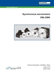
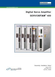
<strong>K4000</strong> <strong>–</strong> <strong>Technical</strong> <strong>Specifications</strong><br />
DANAHER MOTION S.A. La Pierreire 2, CH-1029 Villars-Ste-Croix<br />
Telephone +41-21-631 33 33, Telefax +41-21-636 05 09<br />
E-mail: info@danaher-motion.ch<br />
www.danaher-motion.ch<br />
25-11-03 <strong>K4000</strong> <strong>Technical</strong> <strong>Specifications</strong>
Modifications are reserved<br />
Danaher Motion S.A. CH-1029 Villars-Ste-Croix<br />
Page 2 / 16 <strong>K4000</strong> <strong>Technical</strong> <strong>Specifications</strong>
Danaher Motion S.A. CH-1029 Villars-Ste-Croix<br />
A comprehensive range of product<br />
Product basics<br />
The <strong>K4000</strong> is a high frequency inverter designed for application up to 4000 Hz. The<br />
<strong>K4000</strong> family consists of several models with output ratings from 5 to 120 kVA. the<br />
selective harmonic suppression -SHS - developed by DANAHER MOTION, is aimed<br />
at reducing motor losses and winding stresses without output filter.<br />
• The KEYPAD PC560 control unit can be integrated on the front panel or supplied<br />
as a separate remote control unit.<br />
• The drive is equipped with a RS232 / 422 serial link. A communication protocol in<br />
terminal mode for PC is available on request<br />
• The UL certification of the KT4000 is in process<br />
• The 19” rack version KL4000 will not be UL certified<br />
Main technical data<br />
• Input voltage, all units, 3 x 200 V to 3 x 480 V auto-ranging, no line transformer<br />
• Output voltage VRMS : 0 … UIN, max. 3 x 460 V<br />
• Output frequency range 0 … 4000 Hz<br />
• Ambient temperature 40°C<br />
• Continuous current overload 120% without time limitation<br />
• Max current overload 150% for 1 min / every 10 min<br />
• Short-circuit protection: suitable for use on a circuit capable of delivery not more<br />
than 5000 ARMS symmetrical Amperes, 480 V maximum.<br />
Current and Power ratings<br />
Model Output Current ARMS Typical motor power<br />
Nominal Continuous Peak kW @ 3 x 400 V<br />
KT4005 5 6 10 2.5<br />
KT4010 10 12 15 5<br />
KT4015 15 18 23 7.5<br />
KT4020 20 24 30 10<br />
KT4030 30 36 45 15<br />
Input current:<br />
Input terminals:<br />
All units are rated for a maximal input current of 32 ARMS<br />
10 mm 2<br />
Input cables: Minimum section 6 mm 2 resp. 10 AWG<br />
Use copper conductors 75°C only<br />
Model Output Current ARMS Typical motor power<br />
Nominal Continuous Peak kW @ 3 x 400 V<br />
KT4040 40 50 60 20<br />
KT4060 60 75 90 30<br />
Input current: All units are rated for a maximal input current of 63 ARMS<br />
Input terminals: 35 mm 2<br />
Input cables: Minimum section 25 mm 2 resp. AWG 4<br />
Use copper conductors 75°C only<br />
Model Output Current ARMS Typical motor power<br />
Nominal Continuous Peak kW @ 3 x 400 V<br />
KT4090 90 110 135 45<br />
KT4120 120 145 180 60<br />
Input current: All units are rated for a maximal input current of 160 ARMS<br />
Input terminals: 70 mm 2<br />
Input cables: Minimum section 50 mm 2 resp. AWG 1<br />
Use copper conductors 75°C only<br />
<strong>K4000</strong> <strong>Technical</strong> <strong>Specifications</strong> Page 3 / 16
Danaher Motion S.A. CH-1029 Villars-Ste-Croix<br />
Dissipation and Dynamic Braking Resistors ratings<br />
Model Dissipation Braking resistors<br />
Watts Ω / Watts - external<br />
KT4005 200 22Ω/400W<br />
KT4010 400 22Ω/400W<br />
KT4015 600 22Ω/400W<br />
KT4020 750 15Ω/1200W<br />
KT4030 900 15Ω/1200W<br />
KT4040 1200 6Ω/1500W<br />
KT4060 1800 6Ω/1500W<br />
KT4090 2700 4Ω/2000W<br />
KT4120 3600 4Ω/2000W<br />
Type Part Numbering<br />
Standalone IP20 units<br />
KT40xx-00 Without PC560 and external dynamic braking resistor<br />
KT40xx-01 Without PC560, with external dynamic braking resistor<br />
KT40xx-10 With PC560 and without external dynamic braking resistor<br />
KT40xx-11 With PC560 and with external dynamic braking resistor<br />
IP54 cabinet unit<br />
KU40xx for cabinet with convection cooling up to KU4015<br />
for cabinet with fan cooling for larger power ratings<br />
KV40xx for cabinet with heat exchanger air <strong>–</strong> air<br />
KW40xx for cabinet with heat exchanger air <strong>–</strong> water<br />
KQ40xx for cabinet with air conditioning<br />
Overload protection<br />
UL requires an external overload protection<br />
Page 4 / 16 <strong>K4000</strong> <strong>Technical</strong> <strong>Specifications</strong>
B E<br />
Danaher Motion S.A. CH-1029 Villars-Ste-Croix<br />
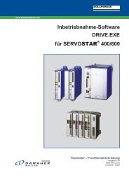
The dimensions of the KT4000<br />
A<br />
D<br />
Model Overall Dimensions Mounting Dimensions Weight<br />
A B C D E F Screws<br />
KT4005<br />
KT4010<br />
KT4015<br />
KT4020<br />
KT4030<br />
KT4040<br />
223 557 265 199 537 7 4 x M6 29 kg<br />
KT4060<br />
KT4090<br />
484 820 350 450 800 11 4 x M10 71 kg<br />
KT4120<br />
91 kg<br />
All dimensions are in mm<br />
Cabinet enclosure<br />
∅ F<br />
1. The cabinet size and / or cabinet fan cooling, heat exchanger, air conditioning must<br />
be sized according the power dissipation shown on the table page 4.<br />
2. The minimum distances between cabinet walls and the drive (left, right, top and<br />
bottom) as well between drives mounted side by side in the same cabinet are 100<br />
mm.<br />
<strong>K4000</strong> <strong>Technical</strong> <strong>Specifications</strong> Page 5 / 16<br />
C
Danaher Motion S.A. CH-1029 Villars-Ste-Croix<br />
The 19” <strong>–</strong> rack versions, KL4000<br />
Current and Power ratings<br />
Model Output Current ARMS Typical motor power<br />
Nominal Continuous Peak kW @ 3 x 400 V<br />
KL4005 5 6 10 2.5<br />
KL4010 10 12 15 5<br />
KL4015 15 18 23 7.5<br />
KL4020 20 24 30 10<br />
KL4030 30 36 45 15<br />
Input current:<br />
Input terminals:<br />
All units are rated for a maximal input current of 32 ARMS<br />
10 mm 2<br />
Input cables: Minimum section 6 mm 2 resp. 10 AWG<br />
Use copper conductors 75°C only<br />
Type Part Numbering<br />
Connection from front<br />
KL40xx-00F Without PC560 and external dynamic braking resistor<br />
KL40xx-01F Without PC560, with external dynamic braking resistor<br />
KL40xx-10F With PC560 and without external dynamic braking resistor<br />
KL40xx-11F With PC560 and with external dynamic braking resistor<br />
Connection from rear<br />
KL40xx-00R Without PC560 and external dynamic braking resistor<br />
KL40xx-01R Without PC560, with external dynamic braking resistor<br />
KL40xx-10R With PC560 and without external dynamic braking resistor<br />
KL40xx-11R With PC560 and with external dynamic braking resistor<br />
The dimensions of the KL4000<br />
All units have the same dimensions<br />
Mounting Instructions<br />
1. The area on top of the 3 fans, whole<br />
width and 112 mm depth, must<br />
remain free for correct cooling of the<br />
heat sink. At least 50 mm must be<br />
available on bottom and top of this<br />
area.<br />
2. On the left side they are ventilation<br />
opening to allow a correct cooling of<br />
the chopper inductance. Those<br />
opening must not be covered.<br />
Unit height: 6U = 265.9 mm<br />
Weight: 29 kg<br />
Page 6 / 16 <strong>K4000</strong> <strong>Technical</strong> <strong>Specifications</strong>
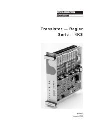
<strong>K4000</strong> - Drive overview<br />
Danaher Motion S.A. CH-1029 Villars-Ste-Croix<br />
The KT4005, KT4010, KT4015, KT4020 and KT4030<br />
Display 2 lines of 20 Characters<br />
Serial link RS485 to control board<br />
Terminal bloc removable cover<br />
Control board with signal control<br />
terminals X2/61 to X2/80<br />
CN4 <strong>–</strong> RS232 / RS422 / D-Sub 9 pins<br />
switchable for direct programming and<br />
controlling of the drive using a PC in<br />
terminal mode<br />
Switching power supply board<br />
and control signal connecting board<br />
Serial link connectors CN2 and<br />
CN3, display or PC connection<br />
X2 - control terminal block X2/01 to X2/60<br />
DC bus capacitors<br />
IGBT drivers<br />
Power connecting board, current<br />
sensing and drive protection<br />
Chopper inductance<br />
Input capacitor<br />
Heat sink with input rectifier and<br />
integrated IGBT modules, including<br />
braking chopper<br />
Input circuit breaker<br />
Input / Output power terminal<br />
block X1<br />
Connecting cables and shielding<br />
grounding clamps with strenght relief<br />
<strong>K4000</strong> <strong>Technical</strong> <strong>Specifications</strong> Page 7 / 16
Danaher Motion S.A. CH-1029 Villars-Ste-Croix<br />
The KT4040 and KT4060<br />
The control board<br />
Switching power supply board<br />
and control signal connecting<br />
board<br />
Power terminal<br />
bloc X1<br />
Input circuit<br />
breaker<br />
IGBT drivers<br />
Chopper<br />
driver<br />
Driver<br />
braking<br />
chopper<br />
Page 8 / 16 <strong>K4000</strong> <strong>Technical</strong> <strong>Specifications</strong>
Danaher Motion S.A. CH-1029 Villars-Ste-Croix<br />
The KT4090 and KT4120<br />
The 3 input<br />
fuses<br />
The Twin-<br />
Chopper drivers<br />
<strong>K4000</strong> <strong>Technical</strong> <strong>Specifications</strong> Page 9 / 16
CN2<br />
CN3<br />
Danaher Motion S.A. CH-1029 Villars-Ste-Croix<br />
The 19” <strong>–</strong> rack version KL4000<br />
X2 control terminals<br />
X1 power terminals<br />
The terminal blocks, connection for front access:<br />
The terminal blocks, connection for access from the back<br />
Page 10 / 16 <strong>K4000</strong> <strong>Technical</strong> <strong>Specifications</strong><br />
CN2<br />
CN3<br />
Circuit breaker<br />
X2 control<br />
terminals<br />
power terminals X1
Danaher Motion S.A. CH-1029 Villars-Ste-Croix<br />
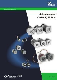
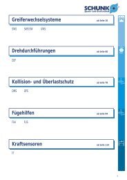
Connecting the dynamic braking resistor<br />
The dynamic braking resistor is a potential free stainless steel heating resistor.<br />
The 2 terminals of the resistor connect to the 2 power terminals X1/B.<br />
The kit shown on the picture consists of the resistance with a 200°C temperature<br />
sensor (opening contact), a protection grid and mounting accessories.<br />
It is mandatory to connect the temperature sensor to the external interlocks to avoid<br />
overheating of the resistance (risk of fire) in case of breakdown of the braking<br />
chopper<br />
The 2 wires of the temperature sensor<br />
connect to terminals X2/39 and X2/40. The 2<br />
wires have to be protected against<br />
accidental contact with the braking resistor<br />
as the temperature of the resistor could<br />
damage the insulation of the wires<br />
Temperature sensor<br />
Contact opens at 200°C<br />
Resistor terminals<br />
Dynamic braking resistor<br />
Thermal<br />
insulating<br />
washers<br />
Dimensions in mm<br />
Protection grid<br />
OPTIONS: Temperature sensor rated at lower level than 200°C. The required<br />
temperature must clearly be specified on order. The unit will get a<br />
specific part number.<br />
<strong>K4000</strong> <strong>Technical</strong> <strong>Specifications</strong> Page 11 / 16
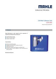
114,5<br />
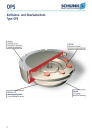
The Tachobox Option<br />
2,3 <strong>–</strong> 3,5V<br />
99<br />
Danaher Motion S.A. CH-1029 Villars-Ste-Croix<br />
0,7 <strong>–</strong> 1,4V<br />
<strong>K4000</strong><br />
Board 7451<br />
CDI+ 19<br />
CDI- 20<br />
+25V 50<br />
AGND 48<br />
R<br />
Sensor<br />
17<br />
TACHOBOX-1<br />
4 Digital speed signal +<br />
5 Digital speed signal -<br />
6 nc<br />
7 +25V<br />
8 AGND<br />
9 nc<br />
10 nc<br />
11 nc<br />
12 nc<br />
Page 12 / 16 <strong>K4000</strong> <strong>Technical</strong> <strong>Specifications</strong><br />
1<br />
2<br />
3<br />
GND<br />
+5V<br />
Signal<br />
TS35
Danaher Motion S.A. CH-1029 Villars-Ste-Croix<br />
<strong>K4000</strong> <strong>–</strong> List of Error messages<br />
Messages Explanation<br />
No communication Fatal error. No communication between the KEYPAD PC580 and<br />
the drive. Check connecting cable.<br />
Freq ctrl assigned on The speed control function has been assigned to TERMINAL BLOC<br />
T.Block<br />
X2 in menu B and you try to change the speed from the KEYPAD<br />
Partition coding is missing You selected the partition coding via the terminal block and no<br />
selection is made. This message is displayed only after a<br />
START command has been issued to the drive.<br />
Partition coding through Partition selection is allocated to TERMINAL BLOC X2 and you<br />
T.Block<br />
Reversing assigned on<br />
T.Block<br />
want to select it using the KEYPAD<br />
The direction reversing function has been assigned to TERMINAL<br />
BLOC X2 in menu B and you try to reverse direction from the<br />
KEYPAD<br />
Access locked The access to Menu B and C is locked by the KEY function on<br />
TERMINAL BLOC X2/47 AND X2/48<br />
Motor overload Im>Iref The converter tripped because the motor current was higher<br />
than the programmed reference current. This function is<br />
programmed in menu C and a relay will be allocated to it. A time<br />
Please wait before<br />
resetting again<br />
delay can be allocated too.<br />
Display when trying to do a RESET when the intermediate DC<br />
bus voltage is still higher than 30 VDC. Just wait for a while and<br />
perform a new reset.<br />
The temperature of the heatsink exceed 75°C<br />
Converter temp.<br />
to high !!!<br />
Motor temperature<br />
to high (PTC)<br />
Overheating of the motor, detected by the PTC<br />
Motor temperature<br />
to high (NTC)<br />
Overheating of the motor, detected by the NTC<br />
External<br />
External interlock circuitry open<br />
Interlocks !!!<br />
See TERMINAL BLOC X2/39 <strong>–</strong> X2/40<br />
Converter<br />
Displayed in case of short-circuit at the output or high current<br />
overloaded<br />
peak exceeding the capacity of the drive.<br />
Defect auxiliary<br />
In case of problem with the auxiliary<br />
supply !!!<br />
power supply 24, ± 15 or 5 VDC<br />
Mains out of<br />
Displayed if your mains voltage is lower than 170 VAC<br />
tolerance !! !<br />
respectively higher than 530 VAC. Any value in between is<br />
considered being within the tolerances<br />
Failure on module No 1 The output power IGBT No1 is broken<br />
Failure on module No 2 The output power IGBT No2 is broken<br />
Failure on module No 3 The output power IGBT No3 is broken<br />
Failure on Chopper module The IGBT of the chopper is broken<br />
Failure on Brake module The IGBT of the braking chopper is broken<br />
"Stop" circuit open !!! When you try to START. Check connection X2/8 <strong>–</strong> X2/9 on<br />
terminal block. This circuitry must be closed to START.<br />
Switch to catch a spinning<br />
motor OPEN<br />
To catch a spinning motor. Check the circuitry X2/45 and X2/46<br />
"Start/Stop” assigned to START function is allocated to TERMINAL BLOC X2 and you tried<br />
Terminal Block<br />
to start using the KEYPAD<br />
"Start/Stop” assigned START function is allocated to KEYPAD and you tried to start<br />
to keypad !!<br />
using the TERMINAL BLOC X2<br />
Not allowed in STOP !!!" You tried to reverse direction in STOP<br />
Access forbidden<br />
The drive is in START mode and you try to access to Menu B or<br />
During WORK<br />
C using the KEYPAD<br />
No errors recorded !!! Displayed after 2ndF H if the memory of failure is empty<br />
<strong>K4000</strong> <strong>Technical</strong> <strong>Specifications</strong> Page 13 / 16
Overview of Menu A, B and C<br />
Menu A: Converter parameters<br />
Display Please copy<br />
Menu A data<br />
Max. current. A<br />
Softwareversion<br />
Date of delivery<br />
Serial number<br />
Running timer<br />
Time power applied<br />
Menu B : Operation / Motors<br />
Display FS CS<br />
0=F 1=GB 2=D 3=I 4=E 1<br />
Menu locking 0=B,C 0<br />
Start/Stop (choice) 0=PC560 0<br />
Speed display units 1=rpm 1<br />
Motor reversing 0=NO 0<br />
Motor reversing 0=PC560 0<br />
Filter analog frequence ctrl. 1<br />
Frequence ctrl 1= 0 to 10V 1<br />
Mains voltage V 400<br />
Partition selection 0=PC560 0<br />
Stop by default ? 0=Coast 0<br />
Delay time s 0<br />
Catch spinning mot. 0=NO 0<br />
PASSWORD: xxx<br />
Partition No = 1<br />
Number of poles 2<br />
Motor power P(kW) 1<br />
Iref source 0=PC560 0<br />
Motor nom. Current Inom A 1<br />
Current accel/decel Iacc A 1<br />
Motor current Iref A 1<br />
If Im>Iref 0=trip 0<br />
RI-compensation V 0<br />
Acceleration time s 10<br />
Deceleration time s 10<br />
Freq ctrl source 0=PC560 0<br />
Default frequency Hz 1<br />
Minimum frequency Hz 1<br />
Pre-set Frequency 1 Hz 0<br />
Pre-set frequency 2 Hz 0<br />
Pre-set frequency 3 Hz 0<br />
Proh. Frequency 1 Hz 0<br />
Proh. Band 1 Hz 0<br />
Proh. Frequency 2 Hz 0<br />
Proh. Band 2 Hz 0<br />
Proh. Frequency 3 Hz 0<br />
Proh. Band 3 Hz 0<br />
Measure speed 0-no 0<br />
Nbre pulses/revolution 0<br />
Slip in % 0<br />
Danaher Motion S.A. CH-1029 Villars-Ste-Croix<br />
Display FS CS<br />
MCM - 3 = none 3<br />
Current Iabs 1 A 0<br />
Current Ish 1 A 0<br />
Current IDTO 1 A 0<br />
Current Iabs 2 A 0<br />
Current Ish 2 A 0<br />
Current IDTO 2 A 0<br />
Current Iabs 3 A 0<br />
Current Ish 3 A 0<br />
Current IDTO 3 A 0<br />
Current Iabs 3 A 0<br />
Current Ish 3 A 0<br />
Current IDTO 3 A 0<br />
FCC duration s 0<br />
FCC current IFCC A 0<br />
Permanent current IFCP A 0<br />
Low freq. smoothing 0<br />
Slip compensation 0<br />
US /FS Pt. 1 US = FS = 1/50<br />
Us/Fs Pt. 2 Us = Fs =<br />
Us/Fs Pt. 3 Us = Fs =<br />
Us/Fs Pt. 4 Us = Fs =<br />
Menu C : Inputs / Outputs<br />
Display<br />
Reached frequency Rel. No = 0<br />
Reached speed Rel. No = 0<br />
Zero frequency Rel. No = 0<br />
Zero speed Rel. No = 0<br />
Start/stop Rel. No = 0<br />
Motor overload Rel. No = 0<br />
MCM output Rel. No = 0<br />
Slip Output Rel. No = 0<br />
Alarm output Rel. No = 0<br />
Comp. output Rel. No = 0<br />
Failure Rel. No = 5<br />
Ext. interlocks Rel. No = 0<br />
Converter overload Rel. No = 0<br />
Def. aux. supply Rel. No = 0<br />
Motor temp (PTC) Rel. No = 0<br />
Converter temp (NTC) Rel. No = 0<br />
Mains anomaly Rel. No = 0<br />
SAN1:1=Fs, 2=Im,<br />
3=N4=Pw, 5=Iw, 6=Us<br />
Output No 1<br />
SAN2:1=Fs, 2=Im,<br />
3=N4=Pw, 5=Iw, 6=Us<br />
Comp. level V<br />
Time delay s<br />
Output No 2<br />
FS : Factory setting<br />
CS : Customer setting<br />
Page 14 / 16 <strong>K4000</strong> <strong>Technical</strong> <strong>Specifications</strong>
We: Danaher Motion S.A<br />
La Pierreire 2<br />
CH1029 Villars-Ste-Croix<br />
Danaher Motion S.A. CH-1029 Villars-Ste-Croix<br />
DECLARATION OF CONFORMITY<br />
declare under our sole responsibility that the products of the family<br />
<strong>K4000</strong><br />
are exclusively designed for incorporation in an other machine. The operation of the product is<br />
submitted to the conformity of the complete equipment, following the provisions of the directive<br />
89/392/EEC<br />
The conformity of the above specified products with the provisions of the Directive 73/23/EEC is<br />
supported by the respect of the standards CEI/IEC 1010-1<br />
If the mounting and connecting instructions of the installation’s manual have been respected, this<br />
product will be conform to the standards EN50081-1 and EN50082-1 relating to the EMC directive<br />
89/336/EEC.<br />
Mounting instructions related to the EMC - directive 89/336/EEC<br />
1. The frequency converter must be mounted in a closed metal cabinet.<br />
2. The power connection between converter and motor must be MADE using shield cable.<br />
3. The control connection must utilize shielded cables.<br />
4. The shield of the cables must be grounded at both ends.<br />
5. Power connections and control connection must be placed in separated canals.<br />
6. A line filter must be installed. The machine manufacturer has the option to use a single filter for<br />
all of his equipment. In this case the correct definition and sizing of the filter is his<br />
responsibility. If the option of a separate filter is selected, this filter will have to match the<br />
following specification:<br />
Units Filter type I Nom (A)<br />
K4005 FMAC0932-2510 25<br />
K4010 FMAC0932-2510 25<br />
K4015 FMAC0932-2510 25<br />
K4020 FMAC0934-3610 36<br />
K4030 FMAC0934-3610 36<br />
K4040 FMAC-0934-5010 50<br />
K4060 FMAC-0937-8010 80<br />
K4090 FMAC-0954-H110 110<br />
K4120 FMAC-0955-H210 180<br />
Supplier: Timonta, Mendrisio (Switzerland)<br />
Villars-Ste-Croix, July 2002<br />
The Engineering Manager: A. Schwendener<br />
<strong>K4000</strong> <strong>Technical</strong> <strong>Specifications</strong> Page 15 / 16
Danaher Motion S.A. CH-1029 Villars-Ste-Croix<br />
Page 16 / 16 <strong>K4000</strong> <strong>Technical</strong> <strong>Specifications</strong>