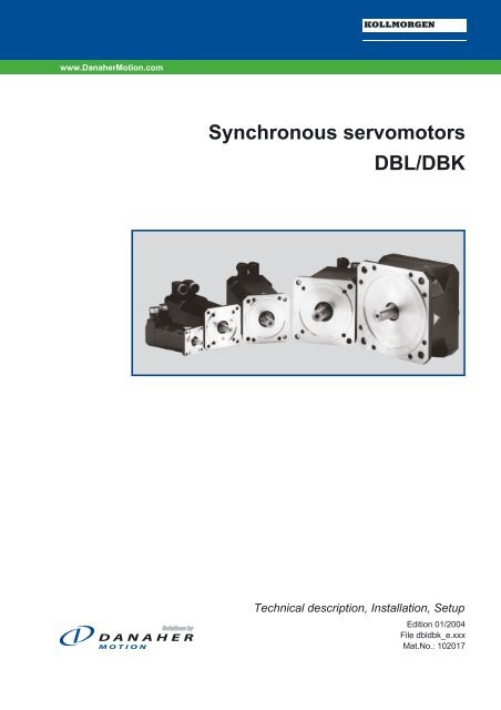
Synchronous servomotors DBL/DBK - BIBUS SK, sro
Synchronous servomotors DBL/DBK - BIBUS SK, sro
Synchronous servomotors DBL/DBK - BIBUS SK, sro

Create successful ePaper yourself
Turn your PDF publications into a flip-book with our unique Google optimized e-Paper software.
www.DanaherMotion.com<br />
<strong>Synchronous</strong> <strong>servomotors</strong><br />
<strong>DBL</strong>/<strong>DBK</strong><br />
Technical description, Installation, Setup<br />
Edition 01/2004<br />
File dbldbk_e.xxx<br />
Mat.No.: 102017
Choose your Motor:<br />
long<br />
short<br />
Type Flange Standstill torque Page<br />
<strong>DBL</strong>1 37 0,1..0,2<br />
<strong>DBL</strong>2 55 0,4..0,8<br />
<strong>DBL</strong>3 75 0,65..3<br />
<strong>DBL</strong>4 105 2,6..9,5<br />
<strong>DBL</strong>5 142 10,5..22<br />
<strong>DBL</strong>6 190 22..29<br />
<strong>DBL</strong>7 190 26..40<br />
<strong>DBL</strong>8 240 40...115<br />
<strong>DBK</strong>4 105 1..1,6<br />
<strong>DBK</strong>5 142 2,1..4,3<br />
<strong>DBK</strong>6 190 3,5..7<br />
<strong>DBK</strong>7 190 6,5..19,5<br />
Already published editions<br />
Edition Comments<br />
04 / 2001 First edition<br />
05 / 2001 some minor corrections<br />
0 0,5 1 5 10 20 30 40 50 70 90 110 130 Nm<br />
07 / 2001 some minor corrections, model number description new, name plate new, dimension drawings optimized<br />
02 / 2002 some minor corrections, encoder dimensions added<br />
07 / 2002 new layout, resolver connection corrected<br />
03 / 2003 new model numbers, dimension drawings corrected<br />
01 / 2004 some minor corrections, Tolerance for technical data supplemented<br />
Technical changes to improve the performance of the equipment may be made without prior notice!<br />
Printed in the Federal Republic of Germany<br />
All rights reserved. No part of this work may be reproduced in any form (by printing, photocopying, microfilm or any other method) or<br />
stored, processed, copied or distributed by electronic means without the written permission of Kollmorgen Corporation.<br />
� 22<br />
� 26<br />
� 30<br />
� 34<br />
� 38<br />
� 42<br />
� 46<br />
� 50<br />
� 54<br />
� 58<br />
� 62<br />
� 66
Kollmorgen 01/2004 Contents<br />
Contents Page<br />
Contents . . . . . . . . . . . . . . . . . . . . . . . . . . . . . . . . . . . . . . . . . . . . . . . . . . . . 3<br />
Safety Notes . . . . . . . . . . . . . . . . . . . . . . . . . . . . . . . . . . . . . . . . . . . . . . . . . 4<br />
Important Notes. . . . . . . . . . . . . . . . . . . . . . . . . . . . . . . . . . . . . . . . . . . . . . . 5<br />
Manufacturer Declaration . . . . . . . . . . . . . . . . . . . . . . . . . . . . . . . . . . . . . . . . 6<br />
Contents<br />
I General<br />
I.1 About this manual ...................................................................................7<br />
I.2 Prescribed usage ...................................................................................7<br />
I.3 Design of the motors. ................................................................................8<br />
I.4 General technical data ...............................................................................8<br />
I.5 Standard features ...................................................................................9<br />
I.5.1 Style .......................................................................................9<br />
I.5.2 Shaft end, A-side. .............................................................................9<br />
I.5.3 Flange ......................................................................................9<br />
I.5.4 Protection class ...............................................................................9<br />
I.5.5 Protective device ..............................................................................9<br />
I.5.6 Insulation material class .......................................................................10<br />
I.5.7 Vibration class ...............................................................................10<br />
I.5.8 Connection method ...........................................................................10<br />
I.5.9 Feedback unit ...............................................................................10<br />
I.5.10 Holding brake ...............................................................................10<br />
I.6 Options ..........................................................................................11<br />
I.7 Selection criteria ...................................................................................11<br />
I.7.1 Model number description ......................................................................12<br />
I.7.2 Nameplate ..................................................................................12<br />
II Installation / Setup<br />
II.1 Important notes. ...................................................................................13<br />
II.2 Assembly / Wiring ..................................................................................14<br />
II.2.1 Connection of the motors ......................................................................16<br />
II.2.1.1 Wiring diagram for resolver motors ...........................................................17<br />
II.2.1.2 Wiring diagram for encoder motors ...........................................................18<br />
II.3 Setup ...........................................................................................19<br />
III Technical data<br />
III.1 Definitions ........................................................................................21<br />
III.2 <strong>DBL</strong>1. ...........................................................................................22<br />
III.3 <strong>DBL</strong>2. ...........................................................................................26<br />
III.4 <strong>DBL</strong>3. ...........................................................................................30<br />
III.5 <strong>DBL</strong>4. ...........................................................................................34<br />
III.6 <strong>DBL</strong>5. ...........................................................................................38<br />
III.7 <strong>DBL</strong>6. ...........................................................................................42<br />
III.8 <strong>DBL</strong>7. ...........................................................................................46<br />
III.9 <strong>DBL</strong>8. ...........................................................................................50<br />
III.10 <strong>DBK</strong>4 ...........................................................................................54<br />
III.11 <strong>DBK</strong>5 ...........................................................................................58<br />
III.12 <strong>DBK</strong>6 ...........................................................................................62<br />
III.13 <strong>DBK</strong>7 ...........................................................................................66<br />
IV Appendix<br />
IV.1 Delivery package, transport, storage, maintenance, disposal ................................................69<br />
IV.2 Removing faults ...................................................................................70<br />
IV.3 Index ............................................................................................71<br />
Servomotors <strong>DBL</strong>/<strong>DBK</strong> 3
Safety notes / Symbols 01/2004 Kollmorgen<br />
Safety Notes<br />
�<br />
�<br />
�<br />
�<br />
�<br />
�<br />
�<br />
�<br />
�<br />
Only properly qualified personnel are permitted to perform such tasks as<br />
transport, assembly, setup and maintenance. Properly qualified personnel<br />
are persons who are familiar with the transport, assembly, installation,<br />
setup and operation of motors, and who have the appropriate qualifications<br />
for their jobs. The qualified personnel must know and observe the following<br />
standards and regulations:<br />
IEC 364 resp. CENELEC HD 384 or DIN VDE 0100<br />
IEC-report 664 or DIN VDE 0110<br />
national regulations for safety and accident prevention or BGV A2<br />
Read the available documentation before assembly and setup. Incorrect<br />
handling of the motors can result in injury and damage to persons and<br />
machinery. Keep strictly to the technical data and the information on the<br />
connection requirements (nameplate and documentation).<br />
The manufacturer of the machine must generate a hazard analysis for the<br />
machine, and take appropriate measures to ensure that unforeseen<br />
movements cannot cause injury or damage to any person or property.<br />
It is vital that you ensure that the motor housing is safely earthed to the<br />
PE(protective earth) busbar in the switch cabinet. Electrical safety is<br />
impossible without a low-resistance earth connection.<br />
Do not unplug any connectors during operation. This creates the danger of<br />
death, severe injury, or extensive material damage.<br />
Power connections may be live even when the motor is not rotating. Never<br />
disconnect the power connections of the motor while the equipment is<br />
energised. This can cause flashovers with resulting injuries to persons and<br />
damage to the contacts.<br />
After disconnecting the servoamplifier from the supply voltage, wait at least<br />
five minutes before touching any components which are normally live (e.g.<br />
contacts, screw connections) or opening any connections.<br />
The capacitors in the servoamplifier can still carry a dangerous voltage up to<br />
five minutes after switching off the supply voltages. To be quite safe,<br />
measure the DC-link voltage and wait until the voltage has fallen below 40V.<br />
The surfaces of the motors can be very hot in operation, according to their<br />
protection category. The surface temperature can reach 100°C. Measure the<br />
temperature, and wait until the motor has cooled down below 40°C before<br />
touching it.<br />
Remove any fitted key (if present) from the shaft before letting the motor run<br />
independently, to avoid the dangerous results of the key being thrown out<br />
by centrifugal forces.<br />
Symbols used in this manual:<br />
Danger to personnel from electricity<br />
and its effects<br />
General warning<br />
general instruction<br />
mechanical hazard<br />
� see chapter (cross reference) � special emphasis<br />
Safety notes / Symbols<br />
4 Servomotors <strong>DBL</strong>/<strong>DBK</strong>
Kollmorgen 01/2004 Important notes<br />
Important Notes<br />
�<br />
�<br />
�<br />
�<br />
�<br />
�<br />
�<br />
Servomotors are precision equipment. The flange and shaft are especially<br />
vulnerable during storage and assembly — so avoid brute force. Precision<br />
requires delicacy. It is important to use the locking thread which is provided<br />
to tighten up couplings, gear wheels or pulley wheels and warm up the drive<br />
components, where possible. Blows or the use of force will lead to damage<br />
to the bearings and the shaft.<br />
Wherever possible, use only backlash-free, frictionally-locking collets or<br />
couplings, e.g. from the manufacturers Baumann & Cie, Gerwah, Jacob, KTR<br />
or Ringspann. Ensure correct alignment of the couplings. A displacement<br />
will cause unacceptable vibration and the destruction of the bearings and<br />
the coupling.<br />
For toothed belts, it is vital to observe the permissible radial forces. An<br />
excessive radial load on the shaft will significantly shorten the life of the<br />
motor.<br />
Avoid axial loads on the motor shaft, as far as possible. Axial loading<br />
significantly shortens the life of the motor.<br />
In all cases, do not create a mechanically constrained motor shaft mounting<br />
by using a rigid coupling with additional external bearings (e.g. in a<br />
gearbox).<br />
For mounting style V3 (shaft end upwards), make sure that no liquid can<br />
enter the upper bearing.<br />
Take note of the no. of motor poles (6-pole) and the no. of resolver poles<br />
(2-pole), and ensure that the correct setting is made in the servoamplifier<br />
which is used. An incorrect setting can lead to the destruction of the motor,<br />
especially with small motors. Important notes<br />
Servomotors <strong>DBL</strong>/<strong>DBK</strong> 5
Manufacturer Declaration 01/2004 Kollmorgen<br />
Manufacturer Declaration<br />
Manufacturer declaration<br />
According to the EG-Machine-guideline 98/37/EC, appendix II B<br />
We, the company<br />
Danaher Motion GmbH<br />
Wacholderstrasse 40-42<br />
40489 Düsseldorf<br />
declare, that the product<br />
Motor series <strong>DBL</strong>/<strong>DBK</strong><br />
(Types <strong>DBL</strong>1, <strong>DBL</strong>2, <strong>DBL</strong>3, <strong>DBL</strong>4, <strong>DBL</strong>5, <strong>DBL</strong>6, <strong>DBL</strong>7, <strong>DBL</strong>8, <strong>DBK</strong>4, <strong>DBK</strong>5, <strong>DBK</strong>6, <strong>DBK</strong>7)<br />
is intended exclusively, in its standard version, for installation in another machine and that its setup is forbidden<br />
until it has been established that the machine into which this product is to be installed conforms to the provisions<br />
of the EC Directive in its version 98/37/ECW<br />
e confirm that the above-mentioned product conforms to the following standards:<br />
73/23/EEC Low voltage directive<br />
VDE 0530 / DIN 57530 Provisions for rotating machinery<br />
DIN 42950 Design<br />
DIN 748 Cylindrical shaft ends<br />
DIN 42955 True running, coaxiality and concentricity<br />
DIN ISO 2373 Vibration class<br />
Issued by: Management<br />
Michael Schulte<br />
This Declaration does not contain any assurance of properties. The notes on safety and protection in the operating<br />
instructions must always be observed.<br />
6 Servomotors <strong>DBL</strong>/<strong>DBK</strong>
Kollmorgen 01/2004 General<br />
I General<br />
I.1 About this manual<br />
This manual describes the <strong>DBL</strong>/<strong>DBK</strong> series of synchronous <strong>servomotors</strong> (standard<br />
version). Among other things, you find information about:<br />
� General description, standard version of the motors Chapter I<br />
� Installation, Setup, Wiring Chapter II<br />
� Technical data, dimensions and characteristics Chapter III<br />
� Notes on Transport, Storage, Maintenance, Disposal Chapter IV<br />
This Manual is intended for the use of qualified staff with professional knowledge of<br />
electrical and mechanical engineering.<br />
The motors are operated in drive systems together with servoamplifiers SERVOSTAR ® . Please<br />
observe the entire system documentation, consisting of:<br />
— Installation and setup instructions for the servoamplifier<br />
— Installation and setup instructions for any expansion card which is connected<br />
— Operating manual for the Operator Software of the servoamplifier<br />
— Technical description of the <strong>DBL</strong>/<strong>DBK</strong> series of motors<br />
I.2 Prescribed usage<br />
The <strong>DBL</strong>/<strong>DBK</strong> series of synchronous <strong>servomotors</strong> is designed especially for drives for industrial<br />
robots, machine tools, textile and packing machinery and similar with high requirements for dynamics.<br />
The user is only permitted to operate the motors under the ambient conditions which are defined in<br />
this documentation.<br />
The <strong>DBL</strong>/<strong>DBK</strong> series of motors is exclusively intended to be driven by servoamplifiers from the<br />
SERVOSTAR series under speed and / or torque control.<br />
The motors are installed as components in electrical apparatus or machines and can only be commissioned<br />
and put into operation as integral components of such apparatus or machines.<br />
The motors must never be connected directly to the mains supply.<br />
The thermal contact which is integrated in the motor windings must be observed and evaluated.<br />
The conformity of the servo-system to the standards mentioned in the manufacturers<br />
declaration on page 6 is only guaranteed when the components (servoamplifier, motor, leads etc.)<br />
that are used have been supplied by us.<br />
Servomotors <strong>DBL</strong>/<strong>DBK</strong> 7
General 01/2004 Kollmorgen<br />
I.3 Design of the motors<br />
<strong>Synchronous</strong> <strong>servomotors</strong> in the <strong>DBL</strong>/<strong>DBK</strong> series are brushless DC motors for demanding servo<br />
applications. When combined with our digital servoamplifiers they are especially suited for positioning<br />
tasks in industrial robots, machine tools, transfer lines etc. With high requirements for dynamics<br />
and stability.<br />
The <strong>servomotors</strong> have permanent magnets in the rotor. The rare earth neodymium -iron-boron<br />
magnetic material is an important factor in making it possible to drive these motors in a highly<br />
dynamic fashion. A three-phase winding which is driven by the servoamplifier is integrated into the<br />
stator. The motor does not have any brushes since commutation is performed electronically by the<br />
servoamplifier.<br />
The temperature of the winding is monitored by temperature sensors in the stator windings and is<br />
signalled via an electrically isolated contact (normally closed, <strong>DBL</strong>1: PTC/3k�).<br />
A resolver is built into the motors as standard feedback element. The servoamplifiers in the<br />
SERVOSTAR series evaluate the resolver position and supply sinusoidal currents to the motors.<br />
The motors can be delivered with or without a built-in holding brake. Retrofitting of the brake is not<br />
possible.<br />
The motors are enamelled in matt black (RAL 9005). This finish is not resistant against solvents<br />
(e.g. trichlorethylene, nitro-thinners, or similar).<br />
I.4 General technical data<br />
Climate category 3K3 to EN 50178<br />
Ambient temperature 5...+40°C for site altitude up to 1000m amsl<br />
(at rated values) It is vital to consult our applications department for<br />
ambient temperatures above 40°C and encapsulated<br />
mounting of the motors.<br />
Permissible humidity 85% rel. humidity, no condensation<br />
(at rated values)<br />
Power derating 1%/Kinrange 40°C...50°C up to 1000m amsl<br />
(currents and torques) for site altitude above 1000m amsl and 40°C<br />
6% up to 2000m amsl<br />
17% up to 3000m amsl<br />
30% up to 4000m amsl<br />
55% up to 5000m amsl<br />
No derating for site altitudes above 1000m amsl<br />
with temperature reduction of 10K / 1000m<br />
Max. permissible flange temperature 65°C at rated values<br />
Ball-bearing life � 20.000 operating hours<br />
Technical data � III<br />
Storage data � IV.1<br />
8 Servomotors <strong>DBL</strong>/<strong>DBK</strong>
Kollmorgen 01/2004 General<br />
I.5 Standard features<br />
I.5.1 Style<br />
The basic style for the <strong>DBL</strong>/<strong>DBK</strong> synchronous motors is style IM B5 according to DIN42950. The<br />
permitted mounting positions may be read from the technical data of the motor series.<br />
I.5.2 Shaft end, A-side<br />
I.5.3 Flange<br />
Power transmission is made through the cylindrical shaft end A (fit k6) to DIN 748, with a locking<br />
thread (except <strong>DBL</strong>1/<strong>DBL</strong>2) but without a fitted-keyway.<br />
If the motors drive via pinions or toothed belts, then high radial forces will occur. The permissible<br />
values at the end of the shaft may be read from the diagrams in chapter III. The maximum values at<br />
rated speed you will find at the technical data. Power take-off from the middle of the free end of the<br />
shaft allows a 10% increase in FR.<br />
The curves are based on a bearing life of 20.000 operating hours.<br />
The axial force FA must not exceed FR/3.<br />
Double-coned collets have proved to be ideal zero-backlash coupling devices, combined, if<br />
required, with metal bellows couplings.<br />
Flange dimensions to IEC standard, fit j6, accuracy according to DIN 42955.<br />
Tolerance class: R<br />
I.5.4 Protection class<br />
Standard version IP65<br />
Standard shaft bushing IP64<br />
Shaft bushing with shaft-sealing ring IP65<br />
I.5.5 Protective device<br />
The standard version of each motor is fitted with a thermostat (electrically isolated, normally closed,<br />
<strong>DBL</strong>1: PTC/3k�). You will find the switching point at the technical data. The thermostat does not<br />
provide any protection against short, heavy overloading. Provided that our preassembled resolver<br />
cable is used, the thermostat contact is integrated into the monitoring system of the digital<br />
servoamplifier SERVOSTAR.<br />
The flange temperature must not exceed 65°C in rated operation. - E.4.929.4/09<br />
Servomotors <strong>DBL</strong>/<strong>DBK</strong> 9
General 01/2004 Kollmorgen<br />
I.5.6 Insulation material class<br />
The motors come up to insulation material class F according to DIN 57530.<br />
I.5.7 Vibration class<br />
The motors are made to vibration class N according to DIN ISO 2373.<br />
I.5.8 Connection method<br />
I.5.9 Feedback unit<br />
I.5.10 Holding brake<br />
Motor series Resolver Power<br />
<strong>DBL</strong>1 Cable Cable<br />
<strong>DBL</strong>2..<strong>DBL</strong>6, <strong>DBK</strong> Connector Connector<br />
<strong>DBL</strong>7, <strong>DBL</strong>8 Connector Terminal box<br />
The mating connectors are not part of the delivery package. We can supply preassembled resolver<br />
and power leads.<br />
In Chapter II.2.1 you will find notes on the cable materials.<br />
The motors are equipped with two-pole hollow-shaft resolvers as standard.<br />
As an option, the motors (except <strong>DBL</strong>1) are available with built in single- (ECN1313) or multiturn<br />
(EQN1325) EnDat-encoders (<strong>DBL</strong>2: ECN 1113 / EQN 1125).<br />
The motor length changes when an encoder is mounted. Retrofitting is not possible.<br />
The motors are optionally available with a holding brake (except <strong>DBL</strong>1).<br />
A permanent magnet brake (24V DC) is integrated into the G-motors. When this brake is de-energized<br />
it blocks the rotor. The holding brakes are designed as standstill brakes and are not<br />
suited for repeated operational braking. If the brake is released then the rotor can be moved without<br />
a remanent torque, the operation is free from backlash! The motor length increases when a holding<br />
brake is mounted.<br />
The holding brake can be controlled directly by SERVOSTAR-servoamplifier (no personal safety !),<br />
the winding is suppressed in the servoamplifier — additional circuitry is not required.<br />
If the holding brake is not controlled directly by the servoamplifier, an additional wiring (e.g. varistor)<br />
is required. Consult our applications department beforehand.<br />
A personal safe operation of the holding brake requires an additional contact (normally opened) in<br />
the braking circuit and an anti-surge-device (e.g. Varistor) for the brake.<br />
Wiring example for SERVOSTAR 600 - A.4.031.1/35<br />
SERVOSTAR 600<br />
10 Servomotors <strong>DBL</strong>/<strong>DBK</strong>
Kollmorgen 01/2004 General<br />
I.6 Options<br />
— Holding brake<br />
Built-in holding brake (� I.5.10).<br />
Motor length increases by the holding brake.<br />
— Radial shaft-sealing rings<br />
A radial shaft-sealing ring can be supplied at extra charge to seal against oil mist and oil<br />
spray. This increases the protection rating of the shaft bushing to IP65. The sealing ring is<br />
not suitable for dry running. When a holding brake is built in, the motor length increases by a<br />
sealing ring for approximately 10mm.<br />
— Vertical mounting sockets<br />
If fitted with angular sockets for feedback and power connectors, the motors are also<br />
available with vertical sockets.<br />
— Keyway<br />
The motors are available with keyway and key inserted according to DIN748<br />
The shaft is balanced with a short (half) key.<br />
— EnDat<br />
A high resolution EnDat-encoder is mounted instead of the resolver (� I.5.9).<br />
The motor length increases by the encoder.<br />
— 2nd Thermostat<br />
An additional thermostat can be applied to the motor winding. The connection takes place<br />
via the power connector resp. the terminal box.<br />
— Forced ventilation<br />
For some motors ventilation bonnets are available which cool the motor electrically.<br />
Connection takes place via a 6-pole angular socket<br />
With the ventilation bonnet mounted, the dimensions and nominal data of the motors vary.<br />
Please consult our applications department.<br />
All options can not be retrofitted.<br />
I.7 Selection criteria<br />
The three-phase <strong>servomotors</strong> are designed to operate with SERVOSTAR servoamplifiers.<br />
Together, both units form a closed speed or torque control loop.<br />
The most important selection criteria are:<br />
— Standstill torque M0 [Nm]<br />
— Rated speed nn [min -1 ]<br />
— Moment of inertia of motor and load J [kgcm²]<br />
— Effective torque (calculated) Mrms [Nm]<br />
When calculating the motors and servoamplifiers which are required, take account of the static load<br />
and the dynamic load (acceleration/braking). Collected formulae and examples of the calculations<br />
are available from our applications department.<br />
Servomotors <strong>DBL</strong>/<strong>DBK</strong> 11
General 01/2004 Kollmorgen<br />
I.7.1 Model number description<br />
Brushless servo motor<br />
<strong>DBL</strong> standard<br />
<strong>DBK</strong> short<br />
Flange size<br />
1 37mm<br />
2 55mm<br />
3 75mm<br />
4 105mm<br />
5 142mm<br />
6 190mm<br />
7 190mm<br />
8 240mm<br />
Rated speed*<br />
L 2000min -1<br />
N 3000min -1<br />
M 4500min -1<br />
H 6000min -1<br />
Z 8000min -1<br />
*atUN = 400V<br />
Torque<br />
M0 [Nm] * 100<br />
Holding brake<br />
0 without<br />
B with<br />
Feedback unit<br />
R2 Resolver, 2-pole<br />
R6 Resolver, 6-pole<br />
3S Encoder singleturn<br />
3M Encoder multiturn<br />
I.7.2 Nameplate<br />
Servomotor-Type<br />
<strong>DBL</strong> 3 H 00130 -0R2-000-S40(-275)<br />
Danaher Motion GmbH<br />
Wacholderstr. 40-42<br />
D-40489 Düsseldorf<br />
www.DanaherMotion.net<br />
Customer Support<br />
Europe Tel. +49 (0)203 / 99790<br />
Italy Tel. +39 (0)362 / 594260<br />
NA Tel. +1 (800) 777-3786<br />
Typ<br />
Mo Nm Isol.Kl. IP<br />
Io A Pn kW U/min @ V<br />
Standstill current<br />
Standstill torque<br />
Insulation material<br />
class<br />
Winding number<br />
Used for motor database,<br />
will not appear on nameplate<br />
Cooling<br />
0 without<br />
V Ventilation<br />
Protection class<br />
4 IP64<br />
5 IP65 with<br />
shaft seal<br />
Thermal protection<br />
S Contact at the<br />
feedb. connector<br />
P PTC at the<br />
feedb. connector<br />
Shaft<br />
0 smooth shaft<br />
K with keyway<br />
Connections<br />
Feedback / Power<br />
00 Connectors<br />
angled to B-side<br />
11 Connectors<br />
angled to A-side<br />
22 Connectors<br />
angled to side<br />
DD Connectors rotateable<br />
VV Connectors vertical<br />
LL Flying leads, 80cm<br />
1T Terminal box<br />
(with feedback connector)<br />
Protection<br />
class<br />
Rated power Rated velocity Mains supply<br />
Serial number<br />
12 Servomotors <strong>DBL</strong>/<strong>DBK</strong>
Kollmorgen 01/2004 Installation / Setup<br />
II Installation / Setup<br />
II.1 Important notes<br />
� Check that the servoamplifier and motor match each other. Compare the rated voltage and<br />
rated current of the unit. Carry out the wiring according to the wiring diagram in the Installation<br />
and Setup Instructions for the servoamplifier. The connections to the motor are shown<br />
on pages 17f. Notes on the connection methods can be found on page 16.<br />
� Ensure that there is proper earthing of the servoamplifier and the motor.<br />
� Route the power and control cables as separately as possible from one another (separation<br />
> 20 cm). This will improve the immunity of the system to electromagnetic interference.<br />
If a motor power cable is used which includes integral brake control leads, then these brake<br />
control leads must be shielded. The shielding must be connected at both ends (see under<br />
Installation Instructions for the servoamplifier).<br />
� Install all cables carrying a heavy current with an adequate cross-section, as per EN 60204.<br />
The recommended cross-section can be found in the Technical data.<br />
Caution!<br />
If a servoamplifier of the series SERVOSTAR 601 ..620 is used and the motor<br />
cable exceeds 25m, a boxed choke (type 3YL-20, manufactured by Kollmorgen)<br />
and motor leads with the following diameters must be used:<br />
Servo amplifier Choke box Max. diameter of the motor lead<br />
SERVOSTAR 601...606 3YL-20 4 x 1mm²<br />
SERVOSTAR 610 3YL-20 4 x 1,5mm²<br />
SERVOSTAR 620 3YL-20 4 x 2,5 mm²<br />
� Connect up all shielding via a wide surface-area contact (low impedance) and metallized<br />
connector housings or EMC-cable glands.<br />
� Check the compliance to the permitted radial and axial forces FR and FA.<br />
When you use a toothed belt drive, the minimal permitted diameter of the pinion e.g. follows<br />
from the equation: d<br />
M<br />
min � 0 �2.<br />
F R<br />
� Ensure that there is adequate heat transfer in the surroundings and the motor flange, so that<br />
the maximum permissible flange temperature is not exceeded in S1 operation.<br />
Caution!<br />
Never undo the electrical connections to the motor while it is energised. A dangerous<br />
voltage, resulting from residual charge, can be still present on the capacitors<br />
up to 5 minutes after switch-off of the mains supply.<br />
Measure the DC-link voltage and wait until it has fallen below 40V.<br />
Even when the motor is not rotating, control and power leads may be live.<br />
Servomotors <strong>DBL</strong>/<strong>DBK</strong> 13
Installation / Setup 01/2004 Kollmorgen<br />
II.2 Assembly / Wiring<br />
Only qualified staff with knowledge of mechanical engineering are permitted to assemble<br />
the motor.<br />
Only staff qualified and trained in electrical engineering are allowed to wire up the motor.<br />
The procedure is described as an example. A different method may be appropriate or necessary,<br />
depending on the application of the equipment.<br />
Warning!<br />
Protect the motor from unacceptable stresses.<br />
Take care, especially during transport and handling, that components are not bent and<br />
that insulation clearances are not altered.<br />
Always make sure that the motors are de-energized during assembly and wiring, i.e. No<br />
voltage may be switched on for any piece of equipment which is to be connected.<br />
Ensure that the switch cabinet remains turned off (barrier, warning signs etc.).<br />
The individual voltages will only be turned on again during setup<br />
Note!<br />
The ground symbol �, which you will find in the wiring diagrams, indicates that<br />
you must provide an electrical connection, with as large a surface area as possible, between<br />
the unit indicated and the mounting plate in the switch cabinet. This connection<br />
is to suppress HF interference and must not be confused with the PE (protective earth)<br />
symbol (protective measure to EN 60204).<br />
To wire up the motor, use the wiring diagrams in the Installation and Setup Instructions<br />
of the servoamplifier which is used.<br />
14 Servomotors <strong>DBL</strong>/<strong>DBK</strong>
Kollmorgen 01/2004 Installation / Setup<br />
The following notes should help you to carry out the assembly and wiring in an appropriate<br />
sequence, without overlooking anything.<br />
Site<br />
Ventilation<br />
Assembly<br />
Cable selection<br />
Earthing<br />
Shielding<br />
Wiring<br />
Check<br />
The site must be free of conductive and aggressive material.<br />
For V3-mounting (shaft end upwards), make sure that no liquids can<br />
enter the bearings. If an encapsulated assembly is required, please<br />
consult our applications department beforehand.<br />
Ensure an unhindered ventilation of the motors and observe the permissible<br />
ambient and flange temperatures.<br />
For ambient temperatures above 40°C please consult our applications<br />
department beforehand.<br />
During assembly, take care that the motor is not overstressed when it<br />
is fixed in place.<br />
Select cables according to EN 60204<br />
See the table in chapter II.1 when cable length exceeds 25m.<br />
Use correct earthing and EMC-shielding according to the Installation<br />
instructions for the servoamplifier which is used. Earth the mounting<br />
plate and motor casing. For connection methods see chapter II.2.1.<br />
— Route power cables as separately as possible from control cables<br />
— Connect up the resolver or encoder.<br />
— Connect the motor leads, install motor chokes close to the<br />
— servoamplifier, connect shields to shielding terminals or EMC<br />
— connectors at both ends<br />
— Connect the holding brake, if used, Connect shielding at both ends.<br />
Final check of the installed wiring, according to the wiring diagram<br />
which was used<br />
Servomotors <strong>DBL</strong>/<strong>DBK</strong> 15
Installation / Setup 01/2004 Kollmorgen<br />
II.2.1 Connection of the motors<br />
� Carry out the wiring in accordance with the valid standards and regulations.<br />
� Only use our preassembled shielded leads for the resolver and power connections.<br />
� Connect up the shielding according to the wiring diagrams in the Installation Instructions for<br />
the servoamplifier.<br />
� Incorrectly installed shielding inevitably leads to EMC interference.<br />
In the table below you find all leads supplied by us. Further information referring to chemical,<br />
mechanical and electrical qualities can be received from our applications department.<br />
Insulating material<br />
Sheathing - PUR (Polyurethane, identification 11Y)<br />
core insulation - PETP (Polyesteraphtalate, identification 12Y)<br />
Capacity<br />
Motor lead - less than 150 pF/m<br />
Resolver lead - less than 120 pF/m<br />
Technical Data<br />
— All leads are UL-listed. The UL-Style-number is printed on the sheathing.<br />
— All leads are suitable for trailing.<br />
— Technical data refer to mobile usage of leads.<br />
Life time: 1 Million bending cycles<br />
— The temperature range refers to the operation temperature.<br />
— Identification: N = numbered cores<br />
F = cores with colour code according to DIN 47100<br />
( ) = shielding<br />
Cores Identification Temperature range Cable diameter Bending radius Remarks<br />
[mm²]<br />
[°C]<br />
[mm]<br />
[mm]<br />
(4x1,0) N -30 / +80 10 100<br />
(4x1,5) N -30 / +80 10,5 105 Motor lead<br />
(4x2,5) N -30 / +80 12,6 125<br />
(4x1,0+(2x0,75)) F -30 / +80 10,5 100 Motor lead with<br />
(4x1,5+(2x0,75)) N -30 / +80 11,5 120 integral brake<br />
(4x2,5+(2x1)) F -30 / +80 14,2 145 control leads<br />
(4x2x0,25) F -30 / +80 7,7 70 Resolver lead<br />
(7x2x0,25) F -30 / +80 9,9 80 Encoder lead<br />
16 Servomotors <strong>DBL</strong>/<strong>DBK</strong>
Kollmorgen 01/2004 Installation / Setup<br />
II.2.1.1 Wiring diagram for resolver motors<br />
- A.4.043.1/01<br />
Servomotors <strong>DBL</strong>/<strong>DBK</strong> 17
Installation / Setup 01/2004 Kollmorgen<br />
II.2.1.2 Wiring diagram for encoder motors<br />
- A.4.043.1/02<br />
18 Servomotors <strong>DBL</strong>/<strong>DBK</strong>
Kollmorgen 01/2004 Installation / Setup<br />
II.3 Setup<br />
The procedure for setup is described as an example. A different method may be appropriate or necessary,<br />
depending on the application of the equipment.<br />
Only specialist personnel with extensive knowledge in the areas of electrical engineering / drive<br />
technology are allowed to commission the drive unit of servoamplifier and motor.<br />
Caution!<br />
Check that all live connection points (terminal boxes) are safe against accidental contact.<br />
Deadly voltages can occur, up to 900V.<br />
Never undo the electrical connections to the motor when it is live. The residual charge<br />
in the capacitors of the servoamplifier can produce dangerous voltages up to 5 minutes<br />
after the mains supply has been switched off.<br />
The surface temperature of the motor can reach 100°C in operation.<br />
Check (measure) the temperature of the motor. Wait until the motor has cooled down<br />
below 40°C before touching it.<br />
Make sure that, even if the drive starts to move unintentionally, no danger can result<br />
for personnel or machinery.<br />
� Check the assembly and orientation of the motor.<br />
� Check the drive components (clutch, gear unit, belt pulley) for the correct seating and setting<br />
(observe the permissible radial and axial forces).<br />
� Check the wiring and connections to the motor and the servoamplifier. Check that the<br />
earthing is correct.<br />
� Test the function of the holding brake, if used. (apply 24V, the brake must be released).<br />
� Check whether the rotor of the motor revolves freely (release the brake, if necessary). Listen<br />
out for grinding noises.<br />
� Check that all the required measures against accidental contact with live and moving parts<br />
have been carried out.<br />
� Carry out any further tests which are specifically required for your system.<br />
� Now commission the drive according to the setup instructions for the servo amplifier.<br />
� In multi-axis systems, individually commission each drive unit (servoamplifier and motor).<br />
Servomotors <strong>DBL</strong>/<strong>DBK</strong> 19
Installation / Setup 01/2004 Kollmorgen<br />
This page has been deliberately left blank.<br />
20 Servomotors <strong>DBL</strong>/<strong>DBK</strong>
Kollmorgen 01/2004 Technical data<br />
III Technical data<br />
III.1 Definitions<br />
Standstill torque M0 [Nm]<br />
The standstill torque can be maintained indefinitely at a speed n=0 min -1 and rated ambient conditions.<br />
Rated torque Mn [Nm]<br />
The rated torque is produced when the motor is drawing the rated current at the rated speed. The<br />
rated torque can be produced indefinitely at the rated speed in continuous operation (S1).<br />
Standstill current I0rms [A]<br />
The standstill current is the effective sinusoidal current which the motor draws during standstill to<br />
produce the standstill torque.<br />
Rated current Inrms [A]<br />
The rated current is the effective sinusoidal current which the motor draws at the rated speed in<br />
order to produce the rated torque.<br />
Peak current (pulse current) I0max [A]<br />
The peak current (effective sinusoidal value) is approximately equivalent to 4-times the rated current.<br />
The actual value is determined by the peak current of the servoamplifier which is used.<br />
Torque constant KTrms [Nm/A]<br />
The torque constant defines how much torque in Nm is produced by the motor with 1A r.m.s. current.<br />
The relationship is M=I x KT (uptoI=2xI0)<br />
Voltage constant KErms [mV/min -1 ]<br />
The voltage constant defines the induced motor EMF, as an effective sinusoidal value between two<br />
terminals, per 1000 rpm<br />
Rotor moment of inertia J [kgcm²]<br />
The constant J is a measure of the acceleration capability of the motor. For instance, at I0 the acceleration<br />
time tb from 0 to 3000 rpm is given as:<br />
m<br />
t s<br />
M s cm J<br />
2<br />
3000 �2�<br />
b [ ]� � � with M0 in Nm and J in kgcm²<br />
4 2<br />
�60<br />
10 �<br />
0<br />
Thermal time constant tth [min]<br />
The constant tth defines the time for the cold motor, under a load of I0, to heat up to an<br />
overtemperature of 0.63 x 10⁵ Kelvin. This temperature rise happens in a much shorter time when<br />
the motor is loaded with the rated current.<br />
Release delay time tBRH [ms] / Application delay time tBRL [ms] of the brake<br />
These constants define the response times of the holding brake when operated with the rated voltage<br />
from the servoamplifier.<br />
Servomotors <strong>DBL</strong>/<strong>DBK</strong> 21
Technical data 01/2004 Kollmorgen<br />
III.2 <strong>DBL</strong>1<br />
The data can have a tolerance of +/- 10%.<br />
Technical data<br />
Data<br />
Symbol<br />
[Unit]<br />
<strong>DBL</strong>1<br />
X00010<br />
<strong>DBL</strong>1<br />
X00020<br />
Electrical data<br />
Standstill torque M0 [Nm] 0,1 0,2<br />
Standstill current I0rms [A] 0,60 0,93<br />
Mains voltage UN [VAC] 230<br />
UN =<br />
230V<br />
UN =<br />
400V<br />
UN =<br />
480V<br />
Rated speed nn [min -1 ] 6000 6000<br />
Rated torque Mn [Nm] 0,09 0,18<br />
Rated current In [A] 0,59 0,89<br />
Rated power Pn [kW] 0,06 0,11<br />
Rated speed nn [min -1 ] — —<br />
Rated torque Mn [Nm] — —<br />
Rated current In [A] — —<br />
Rated power Pn [kW] — —<br />
Rated speed nn [min -1 ] — —<br />
Rated torque Mn [Nm] — —<br />
Rated current In [A] — —<br />
Rated power Pn [kW] — —<br />
Peak current I0max [A] 2,8 4,3<br />
Torque constant KTrms [Nm/A] 0,17 0,22<br />
Voltage constant KErms [mVmin] 10 13<br />
Winding resistance Ph-Ph R20 [�] 38,2 22<br />
Winding inductance Ph-Ph L [mH] 6,5 4,7<br />
Mechanical data<br />
Rotor moment of inertia J [kgcm²] 0,06 0,12<br />
Static friction torque MR [Nm] 0,01 0,01<br />
Thermal time constant tTH [min] 5 7<br />
Weight standard G [kg] 0,7 0,8<br />
Radial load permitted at<br />
shaft end @ 6000 min -1 FR [N] 60<br />
Axial load permitted at<br />
shaft end @ 6000 min -1 FA [N] 20<br />
Motor number 00647R 00670R<br />
Connections and leads<br />
<strong>DBL</strong>1<br />
<strong>DBL</strong>1<br />
Data<br />
X00010<br />
X00020<br />
Power connection cable<br />
Motor cable, shielded 4 x 1<br />
Resolver connection cable<br />
Resolver cable, shielded 4x2x0,25mm²<br />
22 Servomotors <strong>DBL</strong>/<strong>DBK</strong>
Kollmorgen 01/2004 Technical data<br />
Dimensions (drawing in principle)<br />
Pin assignment<br />
The motors of the <strong>DBL</strong>1 series are fitted with loose cables (length approx. 80cm). The cables are<br />
stripped, the power cores are additionally fitted with ferrules. The shielding braids are twisted to a<br />
cord each. The resolver leads are colour-coded according to IEC 757, the power leads (except PE)<br />
are numbered.<br />
Power Cable<br />
Lead Connection<br />
1 U2<br />
2 V2<br />
3 W2<br />
GNYE PE<br />
Resolver Cable<br />
Lead Connection<br />
Pin-No.<br />
Resolver connector<br />
(servoamplifier)<br />
WH - Reference 9<br />
BN + Reference 5<br />
GN - Cosine 7<br />
YE + Cosine 3<br />
GY + Sine 8<br />
PK - Sine 4<br />
BU Thermostat 2<br />
RD<br />
- A.4.043.4/12<br />
Thermostat 6<br />
Servomotors <strong>DBL</strong>/<strong>DBK</strong> 23
Technical data 01/2004 Kollmorgen<br />
Radial-/axial forces at the shaft end<br />
Performance curves<br />
<strong>DBL</strong>1X00010<br />
<strong>DBL</strong>1X00020 - A.4.043.3/12, 044.3/01, 42<br />
24 Servomotors <strong>DBL</strong>/<strong>DBK</strong>
Kollmorgen 01/2004 Technical data<br />
This page has been deliberately left blank.<br />
Servomotors <strong>DBL</strong>/<strong>DBK</strong> 25
Technical data 01/2004 Kollmorgen<br />
III.3 <strong>DBL</strong>2<br />
The data can have a tolerance of +/- 10%.<br />
Technical data<br />
Data<br />
Symbol<br />
[Unit]<br />
<strong>DBL</strong>2<br />
H00040<br />
<strong>DBL</strong>2<br />
H00060<br />
<strong>DBL</strong>2<br />
M00080<br />
<strong>DBL</strong>2<br />
H00080<br />
Electrical data<br />
Standstill torque M0 [Nm] 0,4 0,6 0,8 0,8<br />
Standstill current I0rms [A] 0,93 1,5 0,83 1,49<br />
Mains voltage UN [VAC] 230-480<br />
UN =<br />
230V<br />
UN =<br />
400V<br />
UN =<br />
480V<br />
Rated speed nn [min -1 ] 4500 4500 — 4500<br />
Rated torque Mn [Nm] 0,36 0,55 — 0,72<br />
Rated current In [A] 0,90 1,42 — 1,45<br />
Rated power Pn [kW] 0,17 0,26 — 0,34<br />
Rated speed nn [min -1 ] 6000 6000 4500 6000<br />
Rated torque Mn [Nm] 0,34 0,52 0,72 0,69<br />
Rated current In [A] 0,70 1,27 0,83 1,10<br />
Rated power Pn [kW] 0,21 0,33 0,34 0,43<br />
Rated speed nn [min -1 ] — — — —<br />
Rated torque Mn [Nm] — — — —<br />
Rated current In [A] — — — —<br />
Rated power Pn [kW] — — — —<br />
Peak current I0max [A] 4,3 6,8 3,8 6,8<br />
Torque constant KTrms [Nm/A] 0,43 0,41 0,96 0,54<br />
Voltage constant KErms [mVmin] 26 25 58 33<br />
Winding resistance Ph-Ph R20 [�] 26,5 14,8 47,7 14,7<br />
Winding inductance Ph-Ph L [mH] 20 13,2 43 13<br />
Mechanical data<br />
Rotor moment of inertia J [kgcm²] 0,08 0,11 0,13<br />
Static friction torque MR [Nm] 0,02 0,02 0,02<br />
Thermal time constant tTH [min] 15 20 22<br />
Weight standard G [kg] 1,1 1,25 1,5<br />
Radial load permitted at<br />
shaft end @ 3000 min -1 FR [N] 115<br />
Axial load permitted at<br />
shaft end @ 3000 min -1 FA [N] 40<br />
Motor number 00288R 00558R 00348R 00293R<br />
Brake data<br />
Data Symbol [Unit] Value<br />
Holding torque MBR [Nm] 1,2<br />
Operating voltage UBR [VDC] 24+15/-0%<br />
electrical power PBR [W] 8<br />
Moment of inertia JBR [kgcm²] 0,07<br />
Release delay time tBRH [ms] 15-20<br />
Application delay time tBRL [ms] 5-10<br />
Weight of the brake GBR [kg] 0,3<br />
Connections and leads<br />
<strong>DBL</strong>2 <strong>DBL</strong>2 <strong>DBL</strong>2<br />
Data<br />
H00040 H00060 M00080<br />
Power connection 4 + 4 poles, round, angular<br />
Motor cable, shielded 4 x 1<br />
Motor cable with control leads,<br />
shielded<br />
4x1+2x0,75<br />
Resolver connection 12 poles, round, angular<br />
Resolver cable, shielded 4x2x0,25mm²<br />
Encoder connection (Option) 17 poles, round, angular<br />
Encoder cable, shielded 7x2x0,25mm²<br />
<strong>DBL</strong>2<br />
H00080<br />
26 Servomotors <strong>DBL</strong>/<strong>DBK</strong>
Kollmorgen 01/2004 Technical data<br />
Dimensions (drawing in principle)<br />
Pin assignment<br />
Power connector Resolver connector Encoder connector (Option)<br />
Pin Connection Pin Connection Pin Connection<br />
1 U2 1 n.c. 1 B- (Cosine)<br />
� PE 2 Thermostat 2 0 V (power supply)<br />
3 W2 3 + Cosine 3 A- (Sine)<br />
4 V2 4 - Sine 4 UP (power supply)<br />
5 + Reference 5 DATA<br />
A Brake + 6 Thermostat 6 n.c.<br />
B Brake - 7 - Cosine 7 Thermostat<br />
C 2nd Thermostat (Option) 8 + Sine 8 CLOCK<br />
D 2nd Thermostat (Option) 9 - Reference 9 B+ (Cosine)<br />
10 n.c. 10 0 V (Sense)<br />
11 n.c. 11 A+ (Sine)<br />
12 n.c. 12 UP (Sense)<br />
13 DATA<br />
14 Thermostat<br />
15 CLOCK<br />
16 n.c.<br />
17 n.c.<br />
- A.4.043.4/01, 13<br />
Servomotors <strong>DBL</strong>/<strong>DBK</strong> 27
Technical data 01/2004 Kollmorgen<br />
Radial-/axial forces at the shaft end<br />
Performance curves<br />
<strong>DBL</strong>2H00040<br />
<strong>DBL</strong>2H00060<br />
<strong>DBL</strong>2M00080 - A.4.043.3/01, 044.3/02, 04, 43<br />
28 Servomotors <strong>DBL</strong>/<strong>DBK</strong>
Kollmorgen 01/2004 Technical data<br />
<strong>DBL</strong>2H00080 - A.4.044.3/03<br />
Servomotors <strong>DBL</strong>/<strong>DBK</strong> 29
Technical data 01/2004 Kollmorgen<br />
III.4 <strong>DBL</strong>3<br />
The data can have a tolerance of +/- 10%.<br />
Technical data<br />
Data<br />
Symbol<br />
[Unit]<br />
<strong>DBL</strong>3<br />
N00065<br />
Electrical data<br />
Standstill torque M0 [Nm] 0,65 0,65 1,3 1,3 1,9 2,5 3,0<br />
Standstill current I0rms [A] 0,67 1,08 1,0 1,75 1,5 3,0 2,1<br />
Mains voltage UN [VAC] 230-480<br />
UN =<br />
230V<br />
Rated speed nn [min -1 ] — 3000 — 3000 — 3000 —<br />
Rated torque Mn [Nm] — 0,6 — 1,2 — 2,2 —<br />
Rated current In [A] — 1,05 — 1,6 — 2,7 —<br />
Rated power Pn [kW] — 0,19 — 0,38 — 0,69 —<br />
Rated speed nn [min<br />
UN =<br />
400V<br />
-1 ] 3000 6000 3000 6000 3000 6000 3000<br />
Rated torque Mn [Nm] 0,60 0,48 1,20 1,1 1,6 1,80 2,6<br />
Rated current In [A] 0,65 0,95 0,95 1,5 1,32 2,40 1,90<br />
Rated power Pn [kW] 0,19 0,30 0,38 0,69 0,50 1,13 0,82<br />
UN =<br />
480V<br />
Rated speed nn [min -1 ] 3600 — 3600 — 3600 — 3600<br />
Rated torque Mn [Nm] 0,58 — 1,15 — 1,54 — 2,5<br />
Rated current In [A] 0,59 — 0,90 — 1,21 — 1,73<br />
Rated power Pn [kW] 0,22 — 0,43 — 0,58 — 0,94<br />
Peak current I0max [A] 3,0 5,0 4,5 7,5 6,9 13,9 9,5<br />
Torque constant KTrms [Nm/A] 0,98 0,60 1,28 0,74 1,27 0,83 1,46<br />
Voltage constant KErms[mVmin] 59 36,5 77,5 45 77 50 88<br />
Winding resistance Ph-Ph R20 [�] 79 30,3 35,5 13 21,3 5,1 11,5<br />
Winding inductance Ph-Ph L [mH] 82,8 31 61 22 40 11 25<br />
Mechanical data<br />
Rotor moment of inertia J [kgcm²] 0,5 0,8 1,0 1,4 1,7<br />
Static friction torque MR [Nm] 0,02 0,02 0,03 0,05 0,05<br />
Thermal time constant tTH [min] 25 30 32 32 35<br />
Weight standard G [kg] 1,9 2,3 2,5 3,3 4<br />
Radial load permitted at<br />
shaft end @ 3000 min -1 FR [N] 350<br />
Axial load permitted at<br />
shaft end @ 3000 min -1 FA [N] 110<br />
Motor number 00299R 00276R 00258R 00275R 00263R 00420R 00252R<br />
<strong>DBL</strong>3<br />
H00065<br />
Brake data<br />
Data Symbol [Unit] Value<br />
Holding torque MBR [Nm] 2,5<br />
Operating voltage UBR [VDC] 24+15/-0%<br />
electrical power PBR [W] 12<br />
Moment of inertia JBR [kgcm²] 0,38<br />
Release delay time tBRH [ms] 10-15<br />
Application delay time tBRL [ms] 10-15<br />
Weight of the brake GBR [kg] 0,4<br />
<strong>DBL</strong>3<br />
N00130<br />
<strong>DBL</strong>3<br />
H00130<br />
Connections and leads<br />
<strong>DBL</strong>3 <strong>DBL</strong>3 <strong>DBL</strong>3 <strong>DBL</strong>3 <strong>DBL</strong>3<br />
Data<br />
N00065 H00065 N00130 H00130 M00190<br />
Power connection 4 + 4 poles, round, angular<br />
Motor cable, shielded 4 x 1<br />
Motor cable with control<br />
leads, shielded<br />
4x1+2x0,75<br />
Resolver connection 12 poles, round, angular<br />
Resolver cable, shielded 4x2x0,25mm²<br />
Encoder connection (Option) 17 poles, round, angular<br />
Encoder cable, shielded 7x2x0,25mm²<br />
<strong>DBL</strong>3<br />
M00190<br />
<strong>DBL</strong>3<br />
H00250<br />
<strong>DBL</strong>3<br />
H00250<br />
<strong>DBL</strong>3<br />
N00300<br />
<strong>DBL</strong>3<br />
N00300<br />
30 Servomotors <strong>DBL</strong>/<strong>DBK</strong>
Kollmorgen 01/2004 Technical data<br />
Dimensions (drawing in principle)<br />
Pin assignment<br />
Power connector Resolver connector Encoder connector (Option)<br />
Pin Connection Pin Connection Pin Connection<br />
1 U2 1 n.c. 1 B- (Cosine)<br />
� PE 2 Thermostat 2 0 V (power supply)<br />
3 W2 3 + Cosine 3 A- (Sine)<br />
4 V2 4 - Sine 4 UP (power supply)<br />
5 + Reference 5 DATA<br />
A Brake + (Option) 6 Thermostat 6 n.c.<br />
B Brake - (Option) 7 - Cosine 7 Thermostat<br />
C 2nd Thermostat (Option) 8 + Sine 8 CLOCK<br />
D 2nd Thermostat (Option) 9 - Reference 9 B+ (Cosine)<br />
10 n.c. 10 0 V (Sense)<br />
11 n.c. 11 A+ (Sine)<br />
12 n.c. 12 UP (Sense)<br />
13 DATA<br />
14 Thermostat<br />
15 CLOCK<br />
16 n.c.<br />
17 n.c.<br />
- A.4.043.4/02, 13<br />
Servomotors <strong>DBL</strong>/<strong>DBK</strong> 31
Technical data 01/2004 Kollmorgen<br />
Radial-/axial forces at the shaft end<br />
Performance curves<br />
<strong>DBL</strong>3N00065<br />
<strong>DBL</strong>3H00065<br />
<strong>DBL</strong>3N00130 - A.4.043.3/02, 044.3/05, 09, 10<br />
32 Servomotors <strong>DBL</strong>/<strong>DBK</strong>
Kollmorgen 01/2004 Technical data<br />
<strong>DBL</strong>3H00130<br />
<strong>DBL</strong>3M00190<br />
<strong>DBL</strong>3H00250<br />
<strong>DBL</strong>3N00300 - A.4.044.3/06, 07, 08, 11<br />
Servomotors <strong>DBL</strong>/<strong>DBK</strong> 33
Technical data 01/2004 Kollmorgen<br />
III.5 <strong>DBL</strong>4<br />
The data can have a tolerance of +/- 10%.<br />
Technical data<br />
Data<br />
Symbol<br />
[Unit]<br />
<strong>DBL</strong>4<br />
N00260<br />
Electrical data<br />
Standstill torque M0 [Nm] 2,6 2,6 5,3 5,3 7,5 7,5 9,5<br />
Standstill current I0rms [A] 1,9 3,0 3,2 6,5 4,1 9,3 6,1<br />
Mains voltage UN [VAC] 230-480<br />
UN =<br />
230V<br />
Rated speed nn [min -1 ] — 3000 — 3000 — 3000 —<br />
Rated torque Mn [Nm] — 2,3 — 4,6 — 6,4 —<br />
Rated current In [A] — 2,8 — 6,0 — 8,4 —<br />
Rated power Pn [kW] — 0,72 — 1,45 — 2,01 —<br />
Rated speed nn [min<br />
UN =<br />
400V<br />
-1 ] 3000 — 3000 — 3000 — 3000<br />
Rated torque Mn [Nm] 2,3 — 4,6 — 6,5 — 8<br />
Rated current In [A] 1,76 — 2,77 — 3,7 — 5,6<br />
Rated power Pn [kW] 0,72 — 1,45 — 2,04 — 2,51<br />
UN =<br />
480V<br />
Rated speed nn [min -1 ] 3600 — 3600 — 3600 — 3600<br />
Rated torque Mn [Nm] 2,2 — 4,4 — 6,25 — 7,8<br />
Rated current In [A] 1,62 — 2,68 — 3,38 — 5,03<br />
Rated power Pn [kW] 0,83 — 1,66 — 2,36 — 2,94<br />
Peak current I0max [A] 8,6 13 15 30 19 42,6 27,5<br />
Torque constant KTrms [Nm/A] 1,36 0,86 1,65 0,81 1,85 0,81 1,55<br />
Voltage constant KErms[mVmin 82 52 100 49 112 49 94<br />
Winding resistance Ph-Ph R20 [�] 9,5 3,8 6,14 1,65 3,8 0,86 1,61<br />
Winding inductance Ph-Ph L [mH] 40 15 30 9,3 22,6 5,3 10<br />
Mechanical data<br />
Rotor moment of inertia J [kgcm²] 2,1 2,8 4,3 6,5<br />
Static friction torque MR [Nm] 0,10 0,12 0,15 0,20<br />
Thermal time constant tTH [min] 60 60 66 70 70<br />
Weight standard G [kg] 4,5 5,7 7,6 8,7<br />
Radial load permitted at<br />
shaft end @ 3000 min -1 FR [N] 580<br />
Axial load permitted at<br />
shaft end @ 3000 min -1 FA [N] 180<br />
Motor number 00301R 00285R 00253R 00284R 00254R 00609R 00470R<br />
<strong>DBL</strong>4<br />
H00260<br />
Brake data<br />
Data Symbol [Unit] Value<br />
Holding torque MBR [Nm] 5<br />
Operating voltage UBR [VDC] 24+15/-0%<br />
electrical power PBR [W] 16<br />
Moment of inertia JBR [kgcm²] 1,06<br />
Release delay time tBRH [ms] 10-30<br />
Application delay time tBRL [ms] 5-15<br />
Weight of the brake GBR [kg] 0,75<br />
<strong>DBL</strong>4<br />
N00530<br />
<strong>DBL</strong>4<br />
H00530<br />
Connections and leads<br />
<strong>DBL</strong>4 <strong>DBL</strong>4 <strong>DBL</strong>4 <strong>DBL</strong>4 <strong>DBL</strong>4<br />
Data<br />
N00260 H00260 N00530 H00530 N00750<br />
Power connection 4 + 4 poles, round, angular<br />
Motor cable, shielded 4 x 1,5<br />
Motor cable with control<br />
leads, shielded<br />
4x1+2x0,75<br />
Resolver connection 12 poles, round, angular<br />
Resolver cable, shielded 4x2x0,25mm²<br />
Encoder connection (Option) 17 poles, round, angular<br />
Encoder cable, shielded 7x2x0,25mm²<br />
<strong>DBL</strong>4<br />
N00750<br />
<strong>DBL</strong>4<br />
H00750<br />
<strong>DBL</strong>4<br />
H00750<br />
<strong>DBL</strong>4<br />
N00950<br />
<strong>DBL</strong>4<br />
N00950<br />
34 Servomotors <strong>DBL</strong>/<strong>DBK</strong>
Kollmorgen 01/2004 Technical data<br />
Dimensions (drawing in principle)<br />
Pin assignment<br />
Power connector Resolver connector Encoder connector (Option)<br />
Pin Connection Pin Connection Pin Connection<br />
1 U2 1 n.c. 1 B- (Cosine)<br />
� PE 2 Thermostat 2 0 V (power supply)<br />
3 W2 3 + Cosine 3 A- (Sine)<br />
4 V2 4 - Sine 4 UP (power supply)<br />
5 + Reference 5 DATA<br />
A Brake + (Option) 6 Thermostat 6 n.c.<br />
B Brake - (Option) 7 - Cosine 7 Thermostat<br />
C 2nd Thermostat (Option) 8 + Sine 8 CLOCK<br />
D 2nd Thermostat (Option) 9 - Reference 9 B+ (Cosine)<br />
10 n.c. 10 0 V (Sense)<br />
11 n.c. 11 A+ (Sine)<br />
12 n.c. 12 UP (Sense)<br />
13 DATA<br />
14 Thermostat<br />
15 CLOCK<br />
16 n.c.<br />
17 n.c.<br />
- A.4.043.4/03, 13<br />
Servomotors <strong>DBL</strong>/<strong>DBK</strong> 35
Technical data 01/2004 Kollmorgen<br />
Radial-/axial forces at the shaft end<br />
Performance curves<br />
<strong>DBL</strong>4N00260<br />
<strong>DBL</strong>4H00260<br />
<strong>DBL</strong>4N00530 - A.4.043.3/03, 044.3/12, 15, 16<br />
36 Servomotors <strong>DBL</strong>/<strong>DBK</strong>
Kollmorgen 01/2004 Technical data<br />
<strong>DBL</strong>4H00530<br />
<strong>DBL</strong>4N00750<br />
<strong>DBL</strong>4H00750<br />
<strong>DBL</strong>4N00950 - A.4.044.3/13, 14, 17, 18<br />
Servomotors <strong>DBL</strong>/<strong>DBK</strong> 37
Technical data 01/2004 Kollmorgen<br />
III.6 <strong>DBL</strong>5<br />
The data can have a tolerance of +/- 10%.<br />
Technical data<br />
Data<br />
Symbol<br />
[Unit]<br />
<strong>DBL</strong>5<br />
N01050<br />
Electrical data<br />
Standstill torque M0 [Nm] 10,5 10,5 13,5 13,5 17 17 22<br />
Standstill current I0rms [A] 6,5 14,1 8,7 18,6 10,4 20,0 13,7<br />
Mains voltage UN [VAC] 230-480<br />
UN =<br />
230V<br />
UN =<br />
400V<br />
UN =<br />
480V<br />
Rated speed nn [min -1 ] — 3000 — 3000 — 3000 —<br />
Rated torque Mn [Nm] — 8,5 — 10,7 — 14 —<br />
Rated current In [A] — 13 — 15,7 — 17,3 —<br />
Rated power Pn [kW] — 2,67 — 3,36 — 4,40 —<br />
Rated speed nn [min -1 ] 3000 — 3000 — 3000 — 3000<br />
Rated torque Mn [Nm] 8,5 — 10,7 — 14 — 17<br />
Rated current In [A] 5,7 — 7,3 — 9,1 — 11,3<br />
Rated power Pn [kW] 2,67 — 3,36 — 4,40 — 5,34<br />
Rated speed nn [min -1 ] 3600 — 3600 — 3600 — 3600<br />
Rated torque Mn [Nm] 8 — 10 — 13,4 — 16<br />
Rated current In [A] 5 — 6,45 — 8,17 — 10<br />
Rated power Pn [kW] 3,02 — 3,77 — 5,05 — 6,03<br />
Peak current I0max [A] 30 71 40 85 48 91 63<br />
Torque constant KTrms [Nm/A] 1,6 0,74 1,55 0,73 1,64 0,86 1,6<br />
Voltage constant KErms[mVmin 97 45 94 44 99 52 97<br />
Winding resistance Ph-Ph R20 [�] 2,25 0,52 1,71 0,38 1,25 0,36 0,94<br />
Winding inductance Ph-Ph L [mH] 19,8 4,5 16,5 3,1 12,6 3,3 9<br />
Mechanical data<br />
Rotor moment of inertia J [kgcm²] 8,1 9,1 11,3 13,1<br />
Static friction torque MR [Nm] 0,25 0,30 0,30 0,40<br />
Thermal time constant tTH [min] 50 55 60 75<br />
Weight standard G [kg] 9,8 11,2 14 17<br />
Radial load permitted at<br />
shaft end @ 3000 min -1 FR [N] 640<br />
Axial load permitted at<br />
shaft end @ 3000 min -1 FA [N] 200<br />
Motor number 00666R 00562R 00576R 00633R 00665R 00661R 00620R<br />
<strong>DBL</strong>5<br />
H01050<br />
Brake data<br />
Data Symbol [Unit] Value<br />
Holding torque MBR [Nm] 12<br />
Operating voltage UBR [VDC] 24+15/-0%<br />
electrical power PBR [W] 18<br />
Moment of inertia JBR [kgcm²] 3,6<br />
Release delay time tBRH [ms] 30-60<br />
Application delay time tBRL [ms] 10-20<br />
Weight of the brake GBR [kg] 1,5<br />
Connections and leads<br />
<strong>DBL</strong>5 <strong>DBL</strong>5 <strong>DBL</strong>5 <strong>DBL</strong>5 <strong>DBL</strong>5 <strong>DBL</strong>5 <strong>DBL</strong>5<br />
Data<br />
N01050 H01050 N01350 H01350 N01700 H01700 N02200<br />
Power connection 4 + 4 poles, round, angular<br />
Motor cable, shielded 4 x 1,5 4 x 2,5 4 x 1,5 4 x 2,5 4 x 1,5 4 x 2,5<br />
Motor cable with control 4 x 1,5 4 x 2,5 4 x 1,5 4 x 2,5 4 x 1,5 4 x 2,5<br />
leads, shielded<br />
+ 2 x 0,75 +2x1 + 2 x 0,75 +2x1 + 2 x 0,75 +2x1<br />
Resolver connection 12 poles, round, angular<br />
Resolver cable, shielded 4x2x0,25mm²<br />
Encoder connection (Option) 17 poles, round, angular<br />
Encoder cable, shielded 7x2x0,25mm²<br />
38 Servomotors <strong>DBL</strong>/<strong>DBK</strong><br />
<strong>DBL</strong>5<br />
N01350<br />
<strong>DBL</strong>5<br />
H01350<br />
<strong>DBL</strong>5<br />
N01700<br />
<strong>DBL</strong>5<br />
H01700<br />
<strong>DBL</strong>5<br />
N02200
Kollmorgen 01/2004 Technical data<br />
Dimensions (drawing in principle)<br />
Pin assignment<br />
Power connector Resolver connector Encoder connector (Option)<br />
Pin Connection Pin Connection Pin Connection<br />
1 U2 1 n.c. 1 B- (Cosine)<br />
� PE 2 Thermostat 2 0 V (power supply)<br />
3 W2 3 + Cosine 3 A- (Sine)<br />
4 V2 4 - Sine 4 UP (power supply)<br />
5 + Reference 5 DATA<br />
A Brake + (Option) 6 Thermostat 6 n.c.<br />
B Brake - (Option) 7 - Cosine 7 Thermostat<br />
C 2nd Thermostat (Option) 8 + Sine 8 CLOCK<br />
D 2nd Thermostat (Option) 9 - Reference 9 B+ (Cosine)<br />
10 n.c. 10 0 V (Sense)<br />
11 n.c. 11 A+ (Sine)<br />
12 n.c. 12 UP (Sense)<br />
13 DATA<br />
14 Thermostat<br />
15 CLOCK<br />
16 n.c.<br />
17 n.c.<br />
- A.4.043.4/04, 13<br />
Servomotors <strong>DBL</strong>/<strong>DBK</strong> 39
Technical data 01/2004 Kollmorgen<br />
Radial-/axial forces at the shaft end<br />
Performance curves<br />
<strong>DBL</strong>5N01050<br />
<strong>DBL</strong>5H01050<br />
<strong>DBL</strong>5N01350 - A.4.043.3/04, 044.3/19, 22, 23<br />
40 Servomotors <strong>DBL</strong>/<strong>DBK</strong>
Kollmorgen 01/2004 Technical data<br />
<strong>DBL</strong>5H01350<br />
<strong>DBL</strong>5N01700<br />
<strong>DBL</strong>5H01700<br />
<strong>DBL</strong>5N02200 - A.4.044.3/20, 21, 24, 25<br />
Servomotors <strong>DBL</strong>/<strong>DBK</strong> 41
Technical data 01/2004 Kollmorgen<br />
III.7 <strong>DBL</strong>6<br />
The data can have a tolerance of +/- 10%.<br />
Technical data<br />
Data<br />
Symbol<br />
[Unit]<br />
<strong>DBL</strong>6<br />
N02200<br />
<strong>DBL</strong>6<br />
N02900<br />
Electrical data<br />
Standstill torque M0 [Nm] 22 29<br />
Standstill current I0rms [A] 15,1 17,5<br />
Mains voltage UN [VAC] 230-480<br />
UN =<br />
230V<br />
UN =<br />
400V<br />
UN =<br />
480V<br />
Rated speed nn [min -1 ] — —<br />
Rated torque Mn [Nm] — —<br />
Rated current In [A] — —<br />
Rated power Pn [kW] — —<br />
Rated speed nn [min -1 ] 3000 3000<br />
Rated torque Mn [Nm] 16 20<br />
Rated current In [A] 12 13,5<br />
Rated power Pn [kW] 5,03 6,28<br />
Rated speed nn [min -1 ] 3600 3600<br />
Rated torque Mn [Nm] 14,8 18,4<br />
Rated current In [A] 10,1 11,2<br />
Rated power Pn [kW] 5,58 6,94<br />
Peak current I0max [A] 69,5 81<br />
Torque constant KTrms [Nm/A] 1,46 1,65<br />
Voltage constant KErms [mVmin] 88 100<br />
Winding resistance Ph-Ph R20 [�] 0,72 0,55<br />
Winding inductance Ph-Ph L [mH] 8,5 6,5<br />
Mechanical data<br />
Rotor moment of inertia J [kgcm²] 25,1 38,2<br />
Static friction torque MR [Nm] 0,40 0,40<br />
Thermal time constant tTH [min] 60 70<br />
Weight standard G [kg] 21,5 27<br />
Radial load permitted at<br />
shaft end @ 3000 min -1 FR [N] 680<br />
Axial load permitted at<br />
shaft end @ 3000 min -1 FA [N] 230<br />
Motor number 00332R 00407R<br />
Brake data<br />
Data Symbol [Unit] Value<br />
Holding torque MBR [Nm] 20<br />
Operating voltage UBR [VDC] 24+15/-0%<br />
electrical power PBR [W] 22<br />
Moment of inertia JBR [kgcm²] 9,5<br />
Release delay time tBRH [ms] 20-60<br />
Application delay time tBRL [ms] 10-35<br />
Weight of the brake GBR [kg] 2,75<br />
Connections and leads<br />
<strong>DBL</strong>6<br />
<strong>DBL</strong>6<br />
Data<br />
N02200<br />
N02900<br />
Power connection 4 + 4 poles, round, angular<br />
Motor cable, shielded 4 x 2,5<br />
Motor cable with control<br />
leads, shielded<br />
4x2,5+2x1<br />
Resolver connection 12 poles, round, angular<br />
Resolver cable, shielded 4x2x0,25mm²<br />
Encoder connection (Option) 17 poles, round, angular<br />
Encoder cable, shielded 7x2x0,25mm²<br />
42 Servomotors <strong>DBL</strong>/<strong>DBK</strong>
Kollmorgen 01/2004 Technical data<br />
Dimensions (drawing in principle)<br />
Pin assignment<br />
Power connector Resolver connector Encoder connector (Option)<br />
Pin Connection Pin Connection Pin Connection<br />
1 U2 1 n.c. 1 B- (Cosine)<br />
� PE 2 Thermostat 2 0 V (power supply)<br />
3 W2 3 + Cosine 3 A- (Sine)<br />
4 V2 4 - Sine 4 UP (power supply)<br />
5 + Reference 5 DATA<br />
A Brake + (Option) 6 Thermostat 6 n.c.<br />
B Brake - (Option) 7 - Cosine 7 Thermostat<br />
C 2nd Thermostat (Option) 8 + Sine 8 CLOCK<br />
D 2nd Thermostat (Option) 9 - Reference 9 B+ (Cosine)<br />
10 n.c. 10 0 V (Sense)<br />
11 n.c. 11 A+ (Sine)<br />
12 n.c. 12 UP (Sense)<br />
13 DATA<br />
14 Thermostat<br />
15 CLOCK<br />
16 n.c.<br />
17 n.c.<br />
- A.4.043.4/05, 13<br />
Servomotors <strong>DBL</strong>/<strong>DBK</strong> 43
Technical data 01/2004 Kollmorgen<br />
Radial-/axial forces at the shaft end<br />
Performance curves<br />
<strong>DBL</strong>6N02200<br />
<strong>DBL</strong>6N02900 - A.4.043.3/05, 044.3/26, 27<br />
44 Servomotors <strong>DBL</strong>/<strong>DBK</strong>
Kollmorgen 01/2004 Technical data<br />
This page has been deliberately left blank.<br />
Servomotors <strong>DBL</strong>/<strong>DBK</strong> 45
Technical data 01/2004 Kollmorgen<br />
III.8 <strong>DBL</strong>7<br />
The data can have a tolerance of +/- 10%.<br />
Technical data<br />
Data<br />
Symbol<br />
[Unit]<br />
<strong>DBL</strong>7<br />
N02600<br />
<strong>DBL</strong>7<br />
N03200<br />
<strong>DBL</strong>7<br />
N04000<br />
Electrical data<br />
Standstill torque M0 [Nm] 26 32 40<br />
Standstill current I0rms [A] 17,0 20,0 23,4<br />
Mains voltage UN [VAC] 230-480<br />
UN =<br />
230V<br />
UN =<br />
400V<br />
UN =<br />
480V<br />
Rated speed nn [min -1 ] — — —<br />
Rated torque Mn [Nm] — — —<br />
Rated current In [A] — — —<br />
Rated power Pn [kW] — — —<br />
Rated speed nn [min -1 ] 3000 3000 3000<br />
Rated torque Mn [Nm] 20 23 26<br />
Rated current In [A] 14,1 15,8 17<br />
Rated power<br />
Rated speed<br />
Pn [kW]<br />
nn [min<br />
6,28 7,23 8,17<br />
-1 ] 3600 3600 3600<br />
Rated torque Mn [Nm] 18,8 21 23,2<br />
Rated current In [A] 12,3 13,1 13,6<br />
Rated power Pn [kW] 7,09 7,92 8,75<br />
Peak current I0max [A] 76 89,8 94<br />
Torque constant KTrms [Nm/A] 1,53 1,6 1,71<br />
Voltage constant KErms [mVmin] 92,5 97 103,5<br />
Winding resistance Ph-Ph R20 [�] 0,46 0,36 0,3<br />
Winding inductance Ph-Ph L [mH] 4,5 3,6 2,9<br />
Mechanical data<br />
Rotor moment of inertia J [kgcm²] 97,4 114,1 139,4<br />
Static friction torque MR [Nm] 0,40 0,50 0,60<br />
Thermal time constant tTH [min] 60 67 60<br />
Weight standard G [kg] 28 32,5 40<br />
Radial load permitted at<br />
shaft end @ 3000 min -1 FR [N] 780<br />
Axial load permitted at<br />
shaft end @ 3000 min -1 FA [N] 360<br />
Motor number 00335R 00402R 00450R<br />
Brake data<br />
Data Symbol [Unit] Value<br />
Holding torque MBR [Nm] 20<br />
Operating voltage UBR [VDC] 24+15/-0%<br />
electrical power PBR [W] 22<br />
Moment of inertia JBR [kgcm²] 9,5<br />
Release delay time tBRH [ms] 20-60<br />
Application delay time tBRL [ms] 10-35<br />
Weight of the brake GBR [kg] 3,3<br />
Connections and leads<br />
<strong>DBL</strong>7<br />
<strong>DBL</strong>7<br />
<strong>DBL</strong>7<br />
Data<br />
N02600 N03200 N04000<br />
Power connection Terminal box<br />
Motor cable, shielded 4 x 2,5 4 x 4<br />
Motor cable with control<br />
leads, shielded<br />
4x2,5+2x1 –<br />
Control leads, shielded 4 x 1<br />
Resolver connection 12 poles, round<br />
Resolver cable, shielded 4x2x0,25mm²<br />
Encoder connection (Option) 17 poles, round<br />
Encoder cable, shielded 7x2x0,25mm²<br />
46 Servomotors <strong>DBL</strong>/<strong>DBK</strong>
Kollmorgen 01/2004 Technical data<br />
Dimensions (drawing in principle)<br />
Pin assignment<br />
Terminal box Resolver connector Encoder connector (Option)<br />
Kl. Connection Pin Connection Pin Connection<br />
U U2 1 n.c. 1 B- (Cosine)<br />
� PE 2 Thermostat 2 0 V (power supply)<br />
V V2 3 + Cosine 3 A- (Sine)<br />
W W2 4 - Sine 4 UP (power supply)<br />
5 + Reference 5 DATA<br />
(+) Brake + (Option) 6 Thermostat 6 n.c.<br />
(-) Brake - (Option) 7 - Cosine 7 Thermostat<br />
� 2nd Thermostat (Option) 8 + Sine 8 CLOCK<br />
� 2nd Thermostat (Option) 9 - Reference 9 B+ (Cosine)<br />
10 n.c. 10 0 V (Sense)<br />
11 n.c. 11 A+ (Sine)<br />
12 n.c. 12 UP (Sense)<br />
13 DATA<br />
14 Thermostat<br />
15 CLOCK<br />
16 n.c.<br />
17 n.c.<br />
- A.4.043.4/10, 14<br />
Servomotors <strong>DBL</strong>/<strong>DBK</strong> 47
Technical data 01/2004 Kollmorgen<br />
Radial-/axial forces at the shaft end<br />
Performance curves<br />
<strong>DBL</strong>7N02600<br />
<strong>DBL</strong>7N03200<br />
<strong>DBL</strong>7N04000 - A.4.043.3/06, 044.3/28, 29, 30<br />
48 Servomotors <strong>DBL</strong>/<strong>DBK</strong>
Kollmorgen 01/2004 Technical data<br />
This page has been deliberately left blank.<br />
Servomotors <strong>DBL</strong>/<strong>DBK</strong> 49
Technical data 01/2004 Kollmorgen<br />
III.9 <strong>DBL</strong>8<br />
The data can have a tolerance of +/- 10%.<br />
Technical data<br />
Data<br />
Symbol<br />
[Unit]<br />
<strong>DBL</strong>8<br />
N04000<br />
<strong>DBL</strong>8<br />
N06800<br />
<strong>DBL</strong>8<br />
L09300<br />
<strong>DBL</strong>8<br />
L11500<br />
Electrical data<br />
Standstill torque M0 [Nm] 40 68 93 115<br />
Standstill current I0rms [A] 23 37 34 43<br />
Mains voltage UN [VAC] 230-480<br />
UN =<br />
230V<br />
UN =<br />
400V<br />
UN =<br />
480V<br />
Rated speed nn [min -1 ] — — — —<br />
Rated torque Mn [Nm] — — — —<br />
Rated current In [A] — — — —<br />
Rated power Pn [kW] — — — —<br />
Rated speed nn [min -1 ] 3000 3000 2000 2000<br />
Rated torque Mn [Nm] 32 50 70 85<br />
Rated current In [A] 20 28,6 32 32,5<br />
Rated power Pn [kW] 10,1 15,7 14,7 17,8<br />
Rated speed nn [min -1 ] 3600 3600 — —<br />
Rated torque Mn [Nm] 30,4 45,6 — —<br />
Rated current In [A] 17,5 25 — —<br />
Rated power Pn [kW] 11,5 17,2 — —<br />
Peak current I0max [A] 80 140 118 146<br />
Torque constant KTrms [Nm/A] 1,74 1,85 2,71 2,71<br />
Voltage constant KErms [mVmin] 105 112 164 164<br />
Winding resistance Ph-Ph R20 [�] 0,35 0,12 0,16 0,11<br />
Winding inductance Ph-Ph L [mH] 7,5 3,4 4,4 3,9<br />
Mechanical data<br />
Rotor moment of inertia J [kgcm²] 71,1 113,6 153 190<br />
Static friction torque MR [Nm] 0,70 0,70 0,80 0,80<br />
Thermal time constant tTH [min] 65 65 79 90<br />
Weight standard G [kg] 43 54 74 93<br />
Radial load permitted at<br />
shaft end @ 2000 min -1 FR [N] 1800<br />
Axial load permitted at<br />
shaft end @ 2000 min -1 FA [N] 400<br />
Motor number 00690R 00531R 00672R 00668R<br />
Brake data<br />
Data Symbol [Unit] Value<br />
Holding torque MBR [Nm] 60<br />
Operating voltage UBR [VDC] 24+15/-0%<br />
electrical power PBR [W] 36<br />
Moment of inertia JBR [kgcm²] 57,5<br />
Release delay time tBRH [ms] 150<br />
Application delay time tBRL [ms] 40<br />
Weight of the brake GBR [kg] 5,4<br />
Connections and leads<br />
<strong>DBL</strong>8 <strong>DBL</strong>8 <strong>DBL</strong>8<br />
Data<br />
N04000 N06800 L09300<br />
Power connection Terminal box<br />
Motor cable, shielded 4 x 4 4 x 10<br />
Control leads, shielded 4 x 1<br />
Resolver connection 12 poles, round<br />
Resolver cable, shielded 4x2x0,25mm²<br />
Encoder connection (Option) 17 poles, round<br />
Encoder cable, shielded 7x2x0,25mm²<br />
<strong>DBL</strong>8<br />
L11500<br />
50 Servomotors <strong>DBL</strong>/<strong>DBK</strong>
Kollmorgen 01/2004 Technical data<br />
Dimensions (drawing in principle)<br />
Pin assignment<br />
Terminal box Resolver connector Encoder connector (Option)<br />
Kl. Connection Pin Connection Pin Connection<br />
U U2 1 n.c. 1 B- (Cosine)<br />
� PE 2 Thermostat 2 0 V (power supply)<br />
V V2 3 + Cosine 3 A- (Sine)<br />
W W2 4 - Sine 4 UP (power supply)<br />
5 + Reference 5 DATA<br />
(+) Brake + (Option) 6 Thermostat 6 n.c.<br />
(-) Brake - (Option) 7 - Cosine 7 Thermostat<br />
� 2nd Thermostat (Option) 8 + Sine 8 CLOCK<br />
� 2nd Thermostat (Option) 9 - Reference 9 B+ (Cosine)<br />
10 n.c. 10 0 V (Sense)<br />
11 n.c. 11 A+ (Sine)<br />
12 n.c. 12 UP (Sense)<br />
13 DATA<br />
14 Thermostat<br />
15 CLOCK<br />
16 n.c.<br />
17 n.c.<br />
- A.4.043.4/11, 14<br />
Servomotors <strong>DBL</strong>/<strong>DBK</strong> 51
Technical data 01/2004 Kollmorgen<br />
Radial-/axial forces at the shaft end<br />
Performance curves<br />
<strong>DBL</strong>8N04000<br />
<strong>DBL</strong>8N06800 - A.4.043.3/07, 044.3/33, 34<br />
52 Servomotors <strong>DBL</strong>/<strong>DBK</strong>
Kollmorgen 01/2004 Technical data<br />
<strong>DBL</strong>8L09300<br />
<strong>DBL</strong>8L11500 - A.4.044.3/31, 32<br />
Servomotors <strong>DBL</strong>/<strong>DBK</strong> 53
Technical data 01/2004 Kollmorgen<br />
III.10 <strong>DBK</strong>4<br />
The data can have a tolerance of +/- 10%.<br />
Technical data<br />
Data<br />
Symbol<br />
[Unit]<br />
<strong>DBK</strong>4<br />
N00100<br />
<strong>DBK</strong>4<br />
H00100<br />
<strong>DBK</strong>4<br />
N00160<br />
<strong>DBK</strong>4<br />
H00160<br />
Electrical data<br />
Standstill torque M0 [Nm] 1 1 1,6 1,6<br />
Standstill current I0rms [A] 1,1 1,9 1,1 1,9<br />
Mains voltage UN [VAC] 230-480<br />
UN =<br />
230V<br />
UN =<br />
400V<br />
UN =<br />
480V<br />
Rated speed nn [min -1 ] — 3000 — 3000<br />
Rated torque Mn [Nm] — 0,9 — 1,4<br />
Rated current In [A] — 1,85 — 1,7<br />
Rated power Pn [kW] — 0,28 — 0,44<br />
Rated speed nn [min -1 ] 3000 — 3000 —<br />
Rated torque Mn [Nm] 0,9 — 1,4 —<br />
Rated current In [A] 1,06 — 1 —<br />
Rated power Pn [kW] 0,28 — 0,44 —<br />
Rated speed nn [min -1 ] 3600 — 3600 —<br />
Rated torque Mn [Nm] 0,88 — 1,35 —<br />
Rated current In [A] 0,95 — 0,91 —<br />
Rated power Pn [kW] 0,33 — 0,5 —<br />
Peak current I0max [A] 5 8,7 4,9 7,1<br />
Torque constant KTrms [Nm/A] 0,93 0,53 1,49 0,84<br />
Voltage constant KErms [mVmin] 56 32 90 51<br />
Winding resistance Ph-Ph R20 [�] 38 13 25 7,6<br />
Winding inductance Ph-Ph L [mH] 70 24 68 18<br />
Mechanical data<br />
Rotor moment of inertia J [kgcm²] 0,79 1,28<br />
Static friction torque MR [Nm] 0,10 0,13<br />
Thermal time constant tTH [min] 45 50 55<br />
Weight standard G [kg] 3<br />
Radial load permitted at<br />
shaft end @ 3000 min -1 FR [N] 590<br />
Axial load permitted at<br />
shaft end @ 3000 min -1 FA [N] 180<br />
Motor number 00259R 00017R 00441R 00347R<br />
Brake data<br />
Data Symbol [Unit] Value<br />
Holding torque MBR [Nm] 2,5<br />
Operating voltage UBR [VDC] 24+15/-0%<br />
electrical power PBR [W] 12<br />
Moment of inertia JBR [kgcm²] 0,38<br />
Release delay time tBRH [ms] 10-15<br />
Application delay time tBRL [ms] 10-15<br />
Weight of the brake GBR [kg] 0,45<br />
Connections and leads<br />
<strong>DBK</strong>4 <strong>DBK</strong>4 <strong>DBK</strong>4<br />
Data<br />
N00100 H00100 N00160<br />
Power connection 4 + 4 poles, round, angular<br />
Motor cable, shielded 4 x 1<br />
Motor cable with control<br />
leads, shielded<br />
4x1+2x0,75<br />
Resolver connection 12 poles, round, angular<br />
Resolver cable, shielded 4x2x0,25mm²<br />
Encoder connection (Option) 17 poles, round, angular<br />
Encoder cable, shielded 7x2x0,25mm²<br />
<strong>DBK</strong>4<br />
H00160<br />
54 Servomotors <strong>DBL</strong>/<strong>DBK</strong>
Kollmorgen 01/2004 Technical data<br />
Dimensions (drawing in principle)<br />
Pin assignment<br />
Power connector Resolver connector Encoder connector (Option)<br />
Pin Connection Pin Connection Pin Connection<br />
1 U2 1 n.c. 1 B- (Cosine)<br />
� PE 2 Thermostat 2 0 V (power supply)<br />
3 W2 3 + Cosine 3 A- (Sine)<br />
4 V2 4 - Sine 4 UP (power supply)<br />
5 + Reference 5 DATA<br />
A Brake + (Option) 6 Thermostat 6 n.c.<br />
B Brake - (Option) 7 - Cosine 7 Thermostat<br />
C 2nd Thermostat (Option) 8 + Sine 8 CLOCK<br />
D 2nd Thermostat (Option) 9 - Reference 9 B+ (Cosine)<br />
10 n.c. 10 0 V (Sense)<br />
11 n.c. 11 A+ (Sine)<br />
12 n.c. 12 UP (Sense)<br />
13 DATA<br />
14 Thermostat<br />
15 CLOCK<br />
16 n.c.<br />
17 n.c.<br />
- A.4.043.4/06, 13<br />
Servomotors <strong>DBL</strong>/<strong>DBK</strong> 55
Technical data 01/2004 Kollmorgen<br />
Radial-/axial forces at the shaft end<br />
Performance curves<br />
<strong>DBK</strong>4N00100<br />
<strong>DBK</strong>4H00100 - A.4.043.3/08, 044.3/35, 44<br />
56 Servomotors <strong>DBL</strong>/<strong>DBK</strong>
Kollmorgen 01/2004 Technical data<br />
<strong>DBK</strong>4N00160<br />
<strong>DBK</strong>4H00160 - A.4.044.3/45, 46<br />
Servomotors <strong>DBL</strong>/<strong>DBK</strong> 57
Technical data 01/2004 Kollmorgen<br />
III.11 <strong>DBK</strong>5<br />
The data can have a tolerance of +/- 10%.<br />
Technical data<br />
Data<br />
Symbol<br />
[Unit]<br />
<strong>DBK</strong>5<br />
N00210<br />
<strong>DBK</strong>5<br />
H00210<br />
<strong>DBK</strong>5<br />
N00430<br />
<strong>DBK</strong>5<br />
H00430<br />
Electrical data<br />
Standstill torque M0 [Nm] 2,1 2,1 4,3 4,3<br />
Standstill current I0rms [A] 1,5 4 2,9 5<br />
Mains voltage UN [VAC] 230-480<br />
UN =<br />
230V<br />
UN =<br />
400V<br />
UN =<br />
480V<br />
Rated speed nn [min -1 ] — 3000 — 3000<br />
Rated torque Mn [Nm] — 1,9 — 3,9<br />
Rated current In [A] — 3,94 — 4,8<br />
Rated power Pn [kW] — 0,60 — 1,23<br />
Rated speed nn [min -1 ] 3000 — 3000 —<br />
Rated torque Mn [Nm] 1,9 — 3,9 —<br />
Rated current In [A] 1,5 — 2,8 —<br />
Rated power Pn [kW] 0,60 — 1,23 —<br />
Rated speed nn [min -1 ] 3600 — 3600 —<br />
Rated torque Mn [Nm] 1,8 — 3,8 —<br />
Rated current In [A] 1,32 — 2,55 —<br />
Rated power Pn [kW] 0,68 — 1,43 —<br />
Peak current I0max [A] 7 14,6 13 22,5<br />
Torque constant KTrms [Nm/A] 1,36 0,52 1,49 0,87<br />
Voltage constant KErms [mVmin] 83 32 90 53<br />
Winding resistance Ph-Ph R20 [�] 22 3,1 7,1 2,2<br />
Winding inductance Ph-Ph L [mH] 60 10 32 10<br />
Mechanical data<br />
Rotor moment of inertia J [kgcm²] 4,13 5,78<br />
Static friction torque MR [Nm] 0,15 0,20<br />
Thermal time constant tTH [min] 33 34<br />
Weight standard G [kg] 3,9 6,8<br />
Radial load permitted at<br />
shaft end @ 3000 min -1 FR [N] 640<br />
Axial load permitted at<br />
shaft end @ 3000 min -1 FA [N] 200<br />
Motor number 00374R 00549R 00375R 00345R<br />
Brake data<br />
Data Symbol [Unit] Value<br />
Holding torque MBR [Nm] 5<br />
Operating voltage UBR [VDC] 24+15/-0%<br />
electrical power PBR [W] 16<br />
Moment of inertia JBR [kgcm²] 1,06<br />
Release delay time tBRH [ms] 10-30<br />
Application delay time tBRL [ms] 5-15<br />
Weight of the brake GBR [kg] 0,75<br />
Connections and leads<br />
<strong>DBK</strong>5 <strong>DBK</strong>5 <strong>DBK</strong>5<br />
Data<br />
N00210 H00210 N00430<br />
Power connection 4 + 4 poles, round, angular<br />
Motor cable, shielded 4 x 1<br />
Motor cable with control<br />
leads, shielded<br />
4x1+2x0,75<br />
Resolver connection 12 poles, round, angular<br />
Resolver cable, shielded 4x2x0,25mm²<br />
Encoder connection (Option) 17 poles, round, angular<br />
Encoder cable, shielded 7x2x0,25mm²<br />
<strong>DBK</strong>5<br />
H00430<br />
58 Servomotors <strong>DBL</strong>/<strong>DBK</strong>
Kollmorgen 01/2004 Technical data<br />
Dimensions (drawing in principle)<br />
Pin assignment<br />
Power connector Resolver connector Encoder connector (Option)<br />
Pin Connection Pin Connection Pin Connection<br />
1 U2 1 n.c. 1 B- (Cosine)<br />
� PE 2 Thermostat 2 0 V (power supply)<br />
3 W2 3 + Cosine 3 A- (Sine)<br />
4 V2 4 - Sine 4 UP (power supply)<br />
5 + Reference 5 DATA<br />
A Brake + (Option) 6 Thermostat 6 n.c.<br />
B Brake - (Option) 7 - Cosine 7 Thermostat<br />
C 2nd Thermostat (Option) 8 + Sine 8 CLOCK<br />
D 2nd Thermostat (Option) 9 - Reference 9 B+ (Cosine)<br />
10 n.c. 10 0 V (Sense)<br />
11 n.c. 11 A+ (Sine)<br />
12 n.c. 12 UP (Sense)<br />
13 DATA<br />
14 Thermostat<br />
15 CLOCK<br />
16 n.c.<br />
17 n.c.<br />
- A.4.043.4/07, 13<br />
Servomotors <strong>DBL</strong>/<strong>DBK</strong> 59
Technical data 01/2004 Kollmorgen<br />
Radial-/axial forces at the shaft end<br />
Performance curves<br />
<strong>DBK</strong>5N00210<br />
<strong>DBK</strong>5H00210<br />
<strong>DBK</strong>5N00430 - A.4.043.3/09, 044.3/36, 37, 47<br />
60 Servomotors <strong>DBL</strong>/<strong>DBK</strong>
Kollmorgen 01/2004 Technical data<br />
<strong>DBK</strong>5H00430 - A.4.044.3/48<br />
Servomotors <strong>DBL</strong>/<strong>DBK</strong> 61
Technical data 01/2004 Kollmorgen<br />
III.12 <strong>DBK</strong>6<br />
The data can have a tolerance of +/- 10%.<br />
Technical data<br />
Data<br />
Symbol<br />
[Unit]<br />
<strong>DBK</strong>6<br />
N00350<br />
<strong>DBK</strong>6<br />
N00700<br />
Electrical data<br />
Standstill torque M0 [Nm] 3,5 7<br />
Standstill current I0rms [A] 2,8 5<br />
Mains voltage UN [VAC] 230-480<br />
UN =<br />
230V<br />
UN =<br />
400V<br />
UN =<br />
480V<br />
Rated speed nn [min -1 ] — —<br />
Rated torque Mn [Nm] — —<br />
Rated current In [A] — —<br />
Rated power Pn [kW] — —<br />
Rated speed nn [min -1 ] 3000 3000<br />
Rated torque Mn [Nm] 3 6<br />
Rated current In [A] 2,7 4,6<br />
Rated power Pn [kW] 0,94 1,89<br />
Rated speed nn [min -1 ] 3600 3600<br />
Rated torque Mn [Nm] 2,9 5,7<br />
Rated current In [A] 2,3 4,1<br />
Rated power Pn [kW] 1,09 2,15<br />
Peak current I0max [A] 13 23<br />
Torque constant KTrms [Nm/A] 1,27 1,39<br />
Voltage constant KErms [mVmin] 77 84<br />
Winding resistance Ph-Ph R20 [�] 12 4,4<br />
Winding inductance Ph-Ph L [mH] 56 34<br />
Mechanical data<br />
Rotor moment of inertia J [kgcm²] 8 11,35<br />
Static friction torque MR [Nm] 0,30 0,30<br />
Thermal time constant tTH [min] 31 38<br />
Weight standard G [kg] 5,5 8,7<br />
Radial load permitted at<br />
shaft end @ 3000 min -1 FR [N] 650<br />
Axial load permitted at<br />
shaft end @ 3000 min -1 FA [N] 200<br />
Motor number 00476R 00356R<br />
Brake data<br />
Data Symbol [Unit] Value<br />
Holding torque MBR [Nm] 5<br />
Operating voltage UBR [VDC] 24+15/-0%<br />
electrical power PBR [W] 16<br />
Moment of inertia JBR [kgcm²] 1,06<br />
Release delay time tBRH [ms] 10-30<br />
Application delay time tBRL [ms] 5-15<br />
Weight of the brake GBR [kg] 0,75<br />
Connections and leads<br />
<strong>DBK</strong>6<br />
<strong>DBK</strong>6<br />
Data<br />
N00350<br />
N00700<br />
Power connection 4 + 4 poles, round, angular<br />
Motor cable, shielded 4 x 1<br />
Motor cable with control<br />
leads, shielded<br />
4x1+2x0,75<br />
Resolver connection 12 poles, round, angular<br />
Resolver cable, shielded 4x2x0,25mm²<br />
Encoder connection (Option) 17 poles, round, angular<br />
Encoder cable, shielded 7x2x0,25mm²<br />
62 Servomotors <strong>DBL</strong>/<strong>DBK</strong>
Kollmorgen 01/2004 Technical data<br />
Dimensions (drawing in principle)<br />
Pin assignment<br />
Power connector Resolver connector Encoder connector (Option)<br />
Pin Connection Pin Connection Pin Connection<br />
1 U2 1 n.c. 1 B- (Cosine)<br />
� PE 2 Thermostat 2 0 V (power supply)<br />
3 W2 3 + Cosine 3 A- (Sine)<br />
4 V2 4 - Sine 4 UP (power supply)<br />
5 + Reference 5 DATA<br />
A Brake + (Option) 6 Thermostat 6 n.c.<br />
B Brake - (Option) 7 - Cosine 7 Thermostat<br />
C 2nd Thermostat (Option) 8 + Sine 8 CLOCK<br />
D 2nd Thermostat (Option) 9 - Reference 9 B+ (Cosine)<br />
10 n.c. 10 0 V (Sense)<br />
11 n.c. 11 A+ (Sine)<br />
12 n.c. 12 UP (Sense)<br />
13 DATA<br />
14 Thermostat<br />
15 CLOCK<br />
16 n.c.<br />
17 n.c.<br />
- A.4.043.4/08, 13<br />
Servomotors <strong>DBL</strong>/<strong>DBK</strong> 63
Technical data 01/2004 Kollmorgen<br />
Radial-/axial forces at the shaft end<br />
Performance curves<br />
<strong>DBK</strong>6N00350<br />
<strong>DBK</strong>6N00700 - A.4.043.3/10, 044.3/38, 39<br />
64 Servomotors <strong>DBL</strong>/<strong>DBK</strong>
Kollmorgen 01/2004 Technical data<br />
This page has been deliberately left blank.<br />
Servomotors <strong>DBL</strong>/<strong>DBK</strong> 65
Technical data 01/2004 Kollmorgen<br />
III.13 <strong>DBK</strong>7<br />
The data can have a tolerance of +/- 10%.<br />
Technical data<br />
Data<br />
Symbol<br />
[Unit]<br />
<strong>DBK</strong>7<br />
N00650<br />
<strong>DBK</strong>7<br />
N01200<br />
<strong>DBK</strong>7<br />
N01950<br />
Electrical data<br />
Standstill torque M0 [Nm] 6,5 12 19,5<br />
Standstill current I0rms [A] 4,5 7,5 11,8<br />
Mains voltage UN [VAC] 230-480<br />
UN =<br />
230V<br />
UN =<br />
400V<br />
UN =<br />
480V<br />
Rated speed nn [min -1 ] — — —<br />
Rated torque Mn [Nm] — — —<br />
Rated current In [A] — — —<br />
Rated power Pn [kW] — — —<br />
Rated speed nn [min -1 ] 3000 3000 3000<br />
Rated torque Mn [Nm] 5 10 15<br />
Rated current In [A] 3,8 6,8 10<br />
Rated power Pn [kW] 1,57 3,14 4,71<br />
Rated speed nn [min -1 ] 3600 3600 3600<br />
Rated torque Mn [Nm] 4,7 9,6 14<br />
Rated current In [A] 3,3 5,96 8,48<br />
Rated power Pn [kW] 1,77 3,62 5,28<br />
Peak current I0max [A] 21 34,5 55<br />
Torque constant KTrms [Nm/A] 1,43 1,61 1,65<br />
Voltage constant KErms [mVmin] 87 98 100<br />
Winding resistance Ph-Ph R20 [�] 4,15 1,65 0,9<br />
Winding inductance Ph-Ph L [mH] 22 11,5 7<br />
Mechanical data<br />
Rotor moment of inertia J [kgcm²] 32,36 53,11 69,16<br />
Static friction torque MR [Nm] 0,35 0,40 0,50<br />
Thermal time constant tTH [min] 35 42 52<br />
Weight standard G [kg] 10 14,5 19<br />
Radial load permitted at<br />
shaft end @ 3000 min -1 FR [N] 690<br />
Axial load permitted at<br />
shaft end @ 3000 min -1 FA [N] 230<br />
Motor number 00377R 00378R 00379R<br />
Brake data<br />
Data Symbol [Unit] Value<br />
Holding torque MBR [Nm] 12<br />
Operating voltage UBR [VDC] 24+15/-0%<br />
electrical power PBR [W] 18<br />
Moment of inertia JBR [kgcm²] 3,6<br />
Release delay time tBRH [ms] 30-60<br />
Application delay time tBRL [ms] 10-20<br />
Weight of the brake GBR [kg] 1,5<br />
Connections and leads<br />
<strong>DBK</strong>7<br />
<strong>DBK</strong>7<br />
Data<br />
N00650<br />
N01200<br />
Power connection 4 + 4 poles, round, angular<br />
Motor cable, shielded 4 x 1,5<br />
Motor cable with control<br />
leads, shielded<br />
4x1,5+2x0,75<br />
Resolver connection 12 poles, round, angular<br />
Resolver cable, shielded 4x2x0,25mm²<br />
Encoder connection (Option) 17 poles, round, angular<br />
Encoder cable, shielded 7x2x0,25mm²<br />
<strong>DBK</strong>7<br />
N01950<br />
66 Servomotors <strong>DBL</strong>/<strong>DBK</strong>
Kollmorgen 01/2004 Technical data<br />
Dimensions (drawing in principle)<br />
Pin assignment<br />
Power connector Resolver connector Encoder connector (Option)<br />
Pin Connection Pin Connection Pin Connection<br />
1 U2 1 n.c. 1 B- (Cosine)<br />
� PE 2 Thermostat 2 0 V (power supply)<br />
3 W2 3 + Cosine 3 A- (Sine)<br />
4 V2 4 - Sine 4 UP (power supply)<br />
5 + Reference 5 DATA<br />
A Brake + (Option) 6 Thermostat 6 n.c.<br />
B Brake - (Option) 7 - Cosine 7 Thermostat<br />
C 2nd Thermostat (Option) 8 + Sine 8 CLOCK<br />
D 2nd Thermostat (Option) 9 - Reference 9 B+ (Cosine)<br />
10 n.c. 10 0 V (Sense)<br />
11 n.c. 11 A+ (Sine)<br />
12 n.c. 12 UP (Sense)<br />
13 DATA<br />
14 Thermostat<br />
15 CLOCK<br />
16 n.c.<br />
17 n.c.<br />
- A.4.043.4/09, 13<br />
Servomotors <strong>DBL</strong>/<strong>DBK</strong> 67
Technical data 01/2004 Kollmorgen<br />
Radial-/axial forces at the shaft end<br />
Performance curves<br />
<strong>DBK</strong>7N00650<br />
<strong>DBK</strong>7N01200<br />
<strong>DBK</strong>7N01950 - A.4.043.3/11, 044.3/40, 41, 49<br />
68 Servomotors <strong>DBL</strong>/<strong>DBK</strong>
Kollmorgen 01/2004 Appendix<br />
IV Appendix<br />
IV.1 Delivery package, transport, storage, maintenance, disposal<br />
Delivery package: — Motor from the <strong>DBL</strong>/<strong>DBK</strong> series<br />
— Technical description (documentation), 1 copy per delivery<br />
— Motor package leaflet (short info)<br />
Transport: — Climate category 2K3 to EN 50178<br />
— Transport temperature—25...+70°C, max. 20K/hr change<br />
— Transport humidity rel. humidity 5% - 95% , no condensation<br />
— only by qualified personnel<br />
— only in the manufacturer’s original recyclable packaging<br />
— avoid shocks<br />
— if the packaging is damaged, check the motor for visible damage.<br />
— Inform the carrier and, if appropriate, the manufacturer.<br />
Packaging:<br />
Motor type Carton Pallet or skeleton box Max.stacking height<br />
<strong>DBL</strong>1 X 10<br />
<strong>DBL</strong>2 X 10<br />
<strong>DBL</strong>3 X 6<br />
<strong>DBL</strong>4 X 6<br />
<strong>DBL</strong>5 X 5<br />
<strong>DBL</strong>6 X 1<br />
<strong>DBL</strong>7 X 1<br />
<strong>DBL</strong>8 X 1<br />
<strong>DBK</strong>4 X 6<br />
<strong>DBK</strong>5 X 5<br />
<strong>DBK</strong>6 X 1<br />
<strong>DBK</strong>7 X 1<br />
Storage: — Climate category 1K4 to EN 50178<br />
— Storage temperature —25...+55°C, max. variation 20K/hr.<br />
— Humidity rel. humidity 5% - 95%, no condensation<br />
— only in the manufacturer’s original recyclable packaging<br />
— max. stacking height see table under Packaging<br />
— Storage time unlimited<br />
Maintenance: — Only by qualified personnel<br />
— The ball bearings have a grease packing which is adequate for<br />
— 20,000 hours of operation under normal conditions. The bearings<br />
— should be replaced after 20,000 hours of operation under rated conditions<br />
— Check the motor for bearing noise every 2500 operating hours,<br />
— respectively each year. If any noises are heard, then the operation<br />
— of the motor must stop, the bearings must be replaced.<br />
— Opening the motor invalidates the warranty.<br />
Cleaning: — If the housing is dirty: clean with Isopropanol or similar.<br />
do not immerse or spray<br />
Disposal: — The disposal should be carried out by a certified disposal company.<br />
— Ask us for addresses.<br />
Servomotors <strong>DBL</strong>/<strong>DBK</strong> 69
Appendix 01/2004 Kollmorgen<br />
IV.2 Removing faults<br />
The following table is to be seen as a “First Aid” box. There can be a large number of different reasons<br />
for a fault, depending on the particular conditions in your system. The fault causes described<br />
below are mostly those which directly influence the motor. Peculiarities which show up in the control<br />
loop behaviour can usually be traced back to an error in the parameterization of the servoamplifier.<br />
The documentation for the servoamplifier and the setup software provides information on these<br />
matters.<br />
For multi-axis systems there may be further hidden reasons for faults.<br />
Our applications department can give you further help with your problems.<br />
Fault Possible cause<br />
Measures to remove the cause of the<br />
fault<br />
— Servo-amplifier not enabled<br />
— Supply ENABLE signal<br />
Motor doesn’t<br />
rotate<br />
—<br />
—<br />
—<br />
Break in setpoint lead<br />
Motor phases in wrong sequence<br />
Brake not released<br />
—<br />
—<br />
—<br />
Check setpoint lead<br />
Correct the phase sequence<br />
Check brake controls<br />
— Drive is mechanically blocked<br />
— Check mechanism<br />
Motor runs away — Motor phases in wrong sequence — Correct the phase sequence<br />
Motor oscillates<br />
—<br />
—<br />
Break in the shielding of the resolver cable<br />
amplifier gain to high<br />
—<br />
—<br />
Replace resolver cable<br />
use motor default values<br />
Error message:<br />
brake<br />
—<br />
—<br />
Short-circuit in the supply voltage lead to<br />
the motor holding brake<br />
Faulty motor holding brake<br />
—<br />
—<br />
Remove the short-circuit<br />
Replace motor<br />
Error message: — Motor cable has short-circuit or earth short — Replace cable<br />
output stage fault — Motor has short-circuit or earth short — Replace motor<br />
— Resolver connector is not properly plugged — Check connector<br />
Error message: in<br />
resolver<br />
— Break in resolver cable, cable crushed or<br />
similar<br />
— Check cables<br />
— Motor thermostat has switched<br />
— Wait until the motor has cooled<br />
Error message:<br />
motor temperature<br />
— Loose resolver connector or break in —<br />
down. Then investigate why the<br />
motor becomes so hot.<br />
Check connector, replace resolver<br />
resolver cable<br />
cable if necessary<br />
— Required holding torque too high<br />
— Check the dimensioning<br />
Brake does not<br />
grip<br />
—<br />
—<br />
Brake faulty<br />
Motor shaft axially overloaded<br />
—<br />
—<br />
Replace motor<br />
Check the axial load, reduce it.<br />
Replace motor, since the bearings<br />
have been damaged<br />
70 Servomotors <strong>DBL</strong>/<strong>DBK</strong>
Kollmorgen 01/2004 Appendix<br />
IV.3 Index<br />
Text Page Text Page<br />
A Ambient temperature . . . . . . . . . . . . . . 8<br />
Assembly. . . . . . . . . . . . . . . . . . . . 15<br />
Axial force . . . . . . . . . . . . . . . . . . . . 9<br />
B Break response times . . . . . . . . . . . . . 21<br />
C Connection method . . . . . . . . . . . . . . 10<br />
Contents . . . . . . . . . . . . . . . . . . . . . 3<br />
Coupling . . . . . . . . . . . . . . . . . . . . . 9<br />
D <strong>DBK</strong>4 . . . . . . . . . . . . . . . . . . . . . . 54<br />
<strong>DBK</strong>5 . . . . . . . . . . . . . . . . . . . . . . 58<br />
<strong>DBK</strong>6 . . . . . . . . . . . . . . . . . . . . . . 62<br />
<strong>DBK</strong>7 . . . . . . . . . . . . . . . . . . . . . . 66<br />
<strong>DBL</strong>1 . . . . . . . . . . . . . . . . . . . . . . 22<br />
<strong>DBL</strong>2 . . . . . . . . . . . . . . . . . . . . . . 26<br />
<strong>DBL</strong>3 . . . . . . . . . . . . . . . . . . . . . . 30<br />
<strong>DBL</strong>4 . . . . . . . . . . . . . . . . . . . . . . 34<br />
<strong>DBL</strong>5 . . . . . . . . . . . . . . . . . . . . . . 38<br />
<strong>DBL</strong>6 . . . . . . . . . . . . . . . . . . . . . . 42<br />
<strong>DBL</strong>7 . . . . . . . . . . . . . . . . . . . . . . 46<br />
<strong>DBL</strong>8 . . . . . . . . . . . . . . . . . . . . . . 50<br />
Delivery package. . . . . . . . . . . . . . . . 69<br />
Disposal . . . . . . . . . . . . . . . . . . . . 69<br />
E Earthing . . . . . . . . . . . . . . . . . . . . 15<br />
Encoder . . . . . . . . . . . . . . . . . . . . 10<br />
F Feedback unit . . . . . . . . . . . . . . . . . 10<br />
Flange temperature . . . . . . . . . . . . . . . 8<br />
G Ground symbol . . . . . . . . . . . . . . . . . 14<br />
H Holding brake . . . . . . . . . . . . . . . . . 10<br />
I Insulation material class . . . . . . . . . . . . 10<br />
M Maintenance . . . . . . . . . . . . . . . . . . 69<br />
Manufacturer declaration . . . . . . . . . . . . 6<br />
Model number . . . . . . . . . . . . . . . . . 12<br />
Motor lead . . . . . . . . . . . . . . . . . . . 16<br />
N Nameplate . . . . . . . . . . . . . . . . . . . 12<br />
O Options . . . . . . . . . . . . . . . . . . . . . 11<br />
P Peak current . . . . . . . . . . . . . . . . . . 21<br />
Power derating . . . . . . . . . . . . . . . . . 8<br />
Protection class . . . . . . . . . . . . . . . . . 9<br />
Protective device . . . . . . . . . . . . . . . . 9<br />
R Radial force . . . . . . . . . . . . . . . . . . . 9<br />
Rated current. . . . . . . . . . . . . . . . . . 21<br />
Rated torque . . . . . . . . . . . . . . . . . . 21<br />
Resolver . . . . . . . . . . . . . . . . . . . . 10<br />
Resolver lead . . . . . . . . . . . . . . . . . 16<br />
Rotor moment of inertia . . . . . . . . . . . . 21<br />
S Safety notes . . . . . . . . . . . . . . . . . . . 4<br />
Servo amplifier . . . . . . . . . . . . . . . . . 8<br />
Setup . . . . . . . . . . . . . . . . . . . . . . 19<br />
Shielding . . . . . . . . . . . . . . . . . . . . 15<br />
Site . . . . . . . . . . . . . . . . . . . . . . . 15<br />
Standstill current . . . . . . . . . . . . . . . . 21<br />
Standstill torque . . . . . . . . . . . . . . . . 21<br />
Storage. . . . . . . . . . . . . . . . . . . . . 69<br />
Storage humidity . . . . . . . . . . . . . . . . 69<br />
Storage temperature . . . . . . . . . . . . . . 69<br />
Storage time . . . . . . . . . . . . . . . . . . 69<br />
Style . . . . . . . . . . . . . . . . . . . . . . . 9<br />
T Thermal time constant . . . . . . . . . . . . . 21<br />
Thermostat . . . . . . . . . . . . . . . . . . . 9<br />
Torque constant . . . . . . . . . . . . . . . . 21<br />
Transport . . . . . . . . . . . . . . . . . . . . 69<br />
V Ventilation . . . . . . . . . . . . . . . . . . . 15<br />
Vibration class . . . . . . . . . . . . . . . . . 10<br />
Voltage constant . . . . . . . . . . . . . . . . 21<br />
W Wiring . . . . . . . . . . . . . . . . . . . . . 15<br />
Servomotors <strong>DBL</strong>/<strong>DBK</strong> 71
www.DanaherMotion.com<br />
Sales and Service<br />
We are committed to quality customer service. In order to serve in the most effective way,<br />
please contact your local sales representative for assistance.<br />
If you are unaware of your local sales representative, please contact us.<br />
Europe<br />
Visit the European Danaher Motion web site at www.DanaherMotion.net for Setup Software upgrades,<br />
application notes, technical publications and the most recent version of our product manuals.<br />
Danaher Motion Customer Support - Europe<br />
Internet www.DanaherMotion.net<br />
E-Mail virtapp@danaher-motion.net<br />
Phone: +49(0)203 - 99 79 - 0<br />
Fax: +49(0)203 - 99 79 - 155<br />
North America<br />
Visit the North American Danaher Motion web site at www.DanaherMotion.com for Setup Software<br />
upgrades, application notes, technical publications and the most recent version of our product manuals.<br />
Danaher Motion Customer Support North America<br />
Internet www.DanaherMotion.com<br />
E-Mail customer.support@danahermotion.com<br />
Phone: (815) 226 - 2222<br />
Fax: (815) 226 - 3148