INT'L Shortcut Cartridge Catalogue - Bibus SK, s.r.o.
INT'L Shortcut Cartridge Catalogue - Bibus SK, s.r.o.
INT'L Shortcut Cartridge Catalogue - Bibus SK, s.r.o.

Create successful ePaper yourself
Turn your PDF publications into a flip-book with our unique Google optimized e-Paper software.
Over 35 New Products in this <strong>Catalogue</strong><br />
Relief <strong>Cartridge</strong> Valves<br />
Page 7: The RDDA-3** (series 1) and RDFA-3** (series 2) are<br />
non-adjustable direct-acting relief cartridges. They are<br />
normally closed, pressure-limiting valves used to protect<br />
hydraulic components from pressure transients. When the<br />
pressure at the inlet (port 1) reaches the valve setting, the<br />
valve starts to open to tank (port 2), throttling the flow to<br />
limit the pressure rise. These valves are smooth and quiet,<br />
with essentially zero leakage, dirt tolerant, immune to<br />
silting, and are very fast.<br />
Page 8: The RDDT-Q** (series 1) and RDFT-Q** (series 2)<br />
are direct-acting relief cartridges. They are normally<br />
closed, pressure-limiting valves used to protect hydraulic<br />
components from pressure transients. When the pressure<br />
at the inlet (port 1) reaches the valve setting, the valve<br />
starts to open to tank (port 2), throttling the flow to limit<br />
the pressure rise. These valves are smooth and quiet, with<br />
essentially zero leakage, dirt tolerant, immune to silting,<br />
and are very fast. These CE marked valves are safety<br />
valves that meet the requirements of the European<br />
Directive for Pressurized Devices (PED) 97/23/EC.<br />
Page 12: RP*S are pilot-operated, balanced-poppet relief<br />
cartridges and are normally closed pressure regulating<br />
valves. When the pressure at the inlet (port 1) reaches the<br />
valve setting, the valve starts to open to tank (port 2),<br />
throttling flow to regulate the pressure. These valves are<br />
accurate, smooth, quiet, fast, and have low pressure rise<br />
vs. flow.<br />
Page 11: The RPET, RPGT, RPIT, and RPKT are series 1, 2,<br />
3, and 4 pilot operated soft relief valves which control the<br />
rate of pressure rise in a system as well as maximum<br />
pressure. These valves provide excellent pressure<br />
protection and reduced system shock.<br />
Page 12: The RQCB is a series 0 kick-down, relief valve which<br />
works like a circuit breaker in an electrical system. When<br />
the pressure setting is reached, the valve kicks wide open,<br />
passing flow at low pressure. It stays open until flow to<br />
the valve stops.<br />
Page 15: The RBAN-X** is an electro-proportional, direct<br />
acting pilot relief valve which fits into the Sun T-8A<br />
cavity. This valve has an inverse operation, meaning the<br />
valve is at a maximum setting with no signal to the<br />
solenoid coil. The setting decreases as the signal<br />
increases.<br />
Page 17: The RP*S-8** are seated-style, normally closed<br />
modulating valves with a T-8A cavity. When used with<br />
RBAP proportional relief fitted into this cavity, the RPES<br />
becomes a series 1 proportional relief with low main stage<br />
leakage.<br />
Page 19: RV*S-*** are vented, pilot operated, relief valves<br />
with a seated style main stage. When compared to a<br />
standard spool-type vented relief, this valve provides<br />
lower leakage, and faster response resulting in reduced<br />
overshoot and improved pressure control.<br />
Int’l <strong>Shortcut</strong> <strong>Catalogue</strong> #999-901-312 1<br />
Page 20: The RV*T is a vented, pilot operated, soft relief valve<br />
which controls the rate of pressure rise in a system as well<br />
as the maximum pressure. By providing a smoother,<br />
controlled pressure loading in the non-vented condition,<br />
this valve minimizes shock in systems.<br />
Sequence <strong>Cartridge</strong> Valves<br />
Page 28: The SQBB is a series 0 kick-down sequence valve<br />
used to sequence a function in a system when pressure on<br />
the inlet reaches the valve setting. The valve goes wide<br />
open and stays open until flow to the valve stops.<br />
Reducing/Relieving <strong>Cartridge</strong> Valves<br />
Page 42: The PS*T-*** is a direct acting, pressure reducing/<br />
relieving valve mainstage piloted from port 4. This valve<br />
incorporates a damped construction for stable operation<br />
allowing the use of high reduced pressure.<br />
Counterbalance <strong>Cartridge</strong> Valves<br />
Sun has added a number of fixed setting valves to its<br />
counterbalance line of products: CBB*-X**, (Semirestrictive,<br />
40 L/min.), CBA*-X (Restrictive, 10 L/min.),<br />
CBB*-X (Restrictive, 20 L/min.) and CBC*-X (Standard,<br />
60 L/min.). Fixed-setting, 3-port, T-11A cavity,<br />
counterbalance valves with pilot assist function similar to<br />
the adjustable versions except the fixed setting is pre-set<br />
to a nominal value. These fixed-setting valves are meant<br />
to control an overrunning load. The check valve allows<br />
free flow from the directional valve (port 2) to the load<br />
(port 1), while a direct-acting, pilot-assisted relief valve<br />
controls flow from port 1 to port 2. Pilot assist at port 3<br />
lowers the effective setting of the relief valve at a rate<br />
determined by the pilot ratio. See page 72. Also review<br />
these products at www.sunhydraulics.com. Products:<br />
Counterbalance: Click View All Counterbalance Valves.<br />
Load Control: Load Reactive <strong>Cartridge</strong> Valves<br />
Page 64: MB*A-L** (3:1 pilot ratio), MB*B-L** (1.5:1 pilot<br />
ratio), MB*G-L** (4.5:1 pilot ratio) are load reactive,<br />
non-vented load control valves. This valve is functionally<br />
a 3 port counterbalance valve. It seats as a poppet valve<br />
and modulates as a spool valve.<br />
Page 65: MB*A-X** (3:1 pilot ratio), MB*B-X** (1.5:1 pilot<br />
ratio), MB*G-X** (4.5:1 pilot ratio) are load reactive,<br />
non-vented, fixed setting, load control valves. This valve<br />
is functionally a 3 port counterbalance valve. It seats as a<br />
poppet valve and modulates as a spool valve.<br />
Page 66: MW*A-L** (3:1 pilot ratio), MW*B-L** (1.5:1<br />
pilot ratio), MW*G-L** (4.5:1 pilot ratio) are load<br />
reactive, vented, load control valves. This valve is<br />
functionally a 4 port counterbalance valve. It seats as a<br />
poppet valve and modulates as a spool valve.
Over 35 New Products in this <strong>Catalogue</strong><br />
Load Control: Load Reactive <strong>Cartridge</strong> Valves<br />
(Continued)<br />
Page 67: MW*A-X** (3:1 pilot ratio), MW*B-X** (1.5:1<br />
pilot ratio), MW*G-X** (4.5:1 pilot ratio) are load<br />
reactive, vented, load control valves. This valve is<br />
functionally a 4 port counterbalance valve. It seats as a<br />
poppet valve and modulates as a spool valve.<br />
Load Control: Balanced <strong>Cartridge</strong> Valves<br />
Page 70: The MB*M-X** is a balanced, non-vented, nonrelieving<br />
load control valve. This valve displays<br />
characteristics of a pressure compensating flow control<br />
valve. Performance is best in the meter-out mode with<br />
port 1 being the load and port 2 being tank.<br />
Page 71: The MW*M-X** is a vented, balanced non-relieving,<br />
load control valves that combines a balanced modulating<br />
element with a reverse flow check. This valve displays<br />
characteristics of a pressure compensating flow control<br />
valve. Performance is best in the meter-out mode with<br />
port 1 being the load and port 2 being tank.<br />
Check <strong>Cartridge</strong> Valves<br />
Page 74: CXAA-XB* is a free flow, nose-to-side, check valve<br />
which fits into T-8A cavity.<br />
Logic Element <strong>Cartridge</strong> Valves<br />
Page 110: LO*C-ZD* is a balanced poppet, pilot-to-close,<br />
spring biased closed, logic element with position<br />
indicating switch.<br />
Page 111: LO*O-ZD* is a balanced poppet, pilot-to-close,<br />
spring biased open, logic element with position indicating<br />
switch.<br />
Page 116: The LH*A-X** is a bypass/restrictive, priority<br />
modulating element.<br />
Solenoid Operated <strong>Cartridge</strong> Valves<br />
Page 132: The DTDA-S** is a 2-position, 2-way direct<br />
operating poppet-type directional solenoid valve with soft<br />
shift armature.<br />
Page 133: The DAAL-S** is a 2-position, 2-way, spool-type<br />
pilot solenoid valve with soft shift armature.<br />
Page 134: The DLDA-S** is a 2-position, 2-way spool-type<br />
directional solenoid valve with soft shift armature.<br />
Page 135: The DWDA-X** is a 2-position, 3-way poppet-type<br />
directional solenoid valve.<br />
Page 136: The DBAL-S** is a 2-position, 3-way, spool-type<br />
pilot solenoid valve with soft shift armature.<br />
Page 137: The DMDA-S** is a 2-position, 3-way spool-type<br />
directional solenoid valve with soft shift armature.<br />
Page 138: The DNDA-S** is a 2-position, 4-way spool-type<br />
directional solenoid valve with soft shift armature.<br />
Page 139: The DNDC-X** is a direct acting, solenoid-operated,<br />
4-way, 3-position spool valve that is spring centred to the<br />
neutral position.<br />
Pilot Control <strong>Cartridge</strong> Valves<br />
Page 146: DAAL-X** is a 2-way, solenoid operated,<br />
directional spool-type, pilot valve.<br />
Page 146: DAAL-S** is a 2-position, 2-way, spool-type pilot<br />
solenoid valve with soft shift armature.<br />
Page 150: The DBAL-X** is a 3-way, 2-position, solenoid<br />
operated, directional spool-type, pilot valve.<br />
Page 150: DBAL-S** is a 3-way, 2-position, solenoid operated,<br />
directional spool-type pilot valve with soft shift armature.<br />
Corrosion Resistant <strong>Cartridge</strong> Valves<br />
Sun is continually adding to its line of corrosion resistant<br />
valves. These valve have stainless steel and titanium<br />
external components with heat treated internal<br />
components in carbon and alloy steels. These valves are<br />
recommended for marine, oil and gas industries and for<br />
use in stationary aero-drives. All external components are<br />
qualified by a 1,000 hour salt spray test to ASTM B117-<br />
03. In all cases, the internal working components remain<br />
the same as the standard Sun valve. Where the cartridge<br />
product is offered in corrosion resistant materials, you<br />
will see a note in the bottom right corner of the page. Visit<br />
www.sunhydraulics.com for complete information on<br />
our Corrosion Resistant <strong>Cartridge</strong>s. Products:<br />
<strong>Cartridge</strong>s: Corrosion Resistant: View All Corrosion<br />
Resistant <strong>Cartridge</strong>s for complete information about<br />
these cartridges.<br />
Weatherized Coils and Weatherized Coil Kits<br />
Page 190, 191: Sun’s new weatherized coils and kits are<br />
designed for Sun’s full flow solenoid operated and<br />
electro-proportional cartridge valves. They are protection<br />
against high-pressure wash-downs or marine<br />
environments for Sun’s electrically-actuated cartridge<br />
valves. These coil kits are only available with the<br />
Metri-Pack Series 150-2M connector with a choice of<br />
four voltages.<br />
A weatherization kit is required in conjunction with a<br />
weatherized coil and a modified cavity (consult the Sun<br />
website to view cavity modification instructions for the<br />
use of each kit). The coil is not included in the kits and<br />
must be purchased separately. Weatherization kits are<br />
cartridge model code and cavity dependant. These kits<br />
are intended for new installations only and are not<br />
suitable for retrofitting existing equipment or for<br />
standard Sun bodies.<br />
Consult www.sunhydraulics.com for complete details on<br />
weatherized coils and weatherized coil kits. Go to<br />
Products: <strong>Cartridge</strong>s: Coils: View All Coils: Weatherized<br />
Coils. View individual Weatherized Coil Seal Kit page for<br />
detailed installation instructions.<br />
2 Int’l <strong>Shortcut</strong> <strong>Catalogue</strong> #999-901-312
Contents<br />
Model Codes printed in Red are Preferred Versions of Products shown in this catalogue and most readily available.<br />
Relief <strong>Cartridge</strong> Valves . . . . . . . . . . . . . . . . . . . . . . . . . . . . . . . . 5<br />
Sequence <strong>Cartridge</strong> Valves . . . . . . . . . . . . . . . . . . . . . . . . . . . . 25<br />
Reducing and Reducing/Relieving. . . . . . . . . . . . . . . . . . . . .<br />
<strong>Cartridge</strong> Valves<br />
33<br />
Pilot-to-Open Check <strong>Cartridge</strong> Valves . . . . . . . . . . . . . . . . . 47<br />
Counterbalance <strong>Cartridge</strong> Valves. . . . . . . . . . . . . . . . . . . . . . 51<br />
Load Control: Reactive <strong>Cartridge</strong> Valves . . . . . . . . . . . . . . 63<br />
Load Control: Balanced <strong>Cartridge</strong> Valves . . . . . . . . . . . . . 69<br />
Check <strong>Cartridge</strong> Valves . . . . . . . . . . . . . . . . . . . . . . . . . . . . . . . . 73<br />
Flow Control <strong>Cartridge</strong> Valves . . . . . . . . . . . . . . . . . . . . . . . . . 79<br />
Flow Divider / Combiner <strong>Cartridge</strong> Valves . . . . . . . . . . . . . 93<br />
Logic Elements . . . . . . . . . . . . . . . . . . . . . . . . . . . . . . . . . . . . . . . . 99<br />
Directional <strong>Cartridge</strong> Valves . . . . . . . . . . . . . . . . . . . . . . . . . . . 117<br />
Solenoid Operated <strong>Cartridge</strong> Valves. . . . . . . . . . . . . . . . . . . 131<br />
Pilot Control <strong>Cartridge</strong> Valves . . . . . . . . . . . . . . . . . . . . . . . . . 141<br />
Int’l <strong>Shortcut</strong> <strong>Catalogue</strong> #999-901-312 3<br />
Shuttle <strong>Cartridge</strong> Valves. . . . . . . . . . . . . . . . . . . . . . . . . . . . . . . 155<br />
Circuit Savers. . . . . . . . . . . . . . . . . . . . . . . . . . . . . . . . . . . . . . . . . . 163<br />
Hybrid Relief <strong>Cartridge</strong> Valves . . . . . . . . . . . . . . . . . . . . . . . . 171<br />
General Information . . . . . . . . . . . . . . . . . . . . . . . . . . . . . . . . . . . 177<br />
<strong>Cartridge</strong> Control Options . . . . . . . . . . . . . . . . . . . . . . . . . . . . . . . . . 178<br />
<strong>Cartridge</strong> Control Kits . . . . . . . . . . . . . . . . . . . . . . . . . . . . . . . . . . . . 179<br />
Cavity Plugs . . . . . . . . . . . . . . . . . . . . . . . . . . . . . . . . . . . . . . . . . . . . 183<br />
Sun Coil Options for Solenoids (Metal Housing, Round) . . . . . . . . . 187<br />
Sun Coil Options with Embedded Electronic. . . . . . . . . . . . . . . . . . . 188<br />
Proportional Amplifiers<br />
Sun Weatherized Coils and Coil Kits . . . . . . . . . . . . . . . . . . . . . . . . . 190<br />
Sun Coil 790-***** Part Numbering System . . . . . . . . . . . . . . . . . . 191<br />
Orifice Pressure Drop Data. . . . . . . . . . . . . . . . . . . . . . . . . . . . . . . . . 192<br />
Sun Model Code System . . . . . . . . . . . . . . . . . . . . . . . . . . . . . . 193<br />
Sun Model Code Index. . . . . . . . . . . . . . . . . . . . . . . . . . . . . . . . . 194<br />
Warranty . . . . . . . . . . . . . . . . . . . . . . . . . . . . . . . . . . . . . . . . . . . . . . . 199<br />
International Distribution . . . . . . . . . . . . . . . . . . . . . . . . . . . . . . 200
Specifications, descriptions and illustrative material contained herein were accurate as known at the<br />
time this publication was approved for printing.<br />
Sun Hydraulics reserves the right to discontinue models at any time, or change prices, specifications<br />
or designs without notice or incurring obligation.<br />
All rights reserved. This book, or any part thereof, may not be reproduced or transmitted in any form<br />
or by any means, electronic or mechanical, including photocopying, recording,<br />
or information storage and retrieval systems, for any purpose<br />
without the express written permission of Sun Hydraulics Corporation,<br />
1500 West University Parkway, Sarasota, Florida, 34243, USA.<br />
Copyright © 2009 Sun Hydraulics Corporation<br />
Sarasota, FL 34243 USA<br />
Printed in the United States of America<br />
4 Int’l <strong>Shortcut</strong> <strong>Catalogue</strong> #999-901-312
2 1<br />
2<br />
2<br />
2<br />
1<br />
1<br />
1<br />
2 1<br />
2 1<br />
2 1<br />
2<br />
Air Pilot<br />
1<br />
2 1<br />
2 1<br />
2<br />
2<br />
T-8A<br />
Cav<br />
T-8A<br />
Cav<br />
1<br />
1<br />
3<br />
2 1<br />
3<br />
2 1<br />
3<br />
2 1<br />
2<br />
4<br />
3<br />
2 1<br />
3<br />
4 T-8A<br />
Cav<br />
2<br />
3<br />
1<br />
1<br />
Int’l <strong>Shortcut</strong> <strong>Catalogue</strong> #999-901-312 5<br />
Relief <strong>Cartridge</strong> Valves<br />
<strong>Cartridge</strong> Type Page<br />
Pilot Operated, Balanced Piston 6<br />
Direct Acting and Direct Acting, Non-Adjustable 7<br />
Direct Acting, CE Marked 8<br />
Direct Acting, Pilot Capacity 9<br />
Pilot Operated, Balanced Poppet 10<br />
Pilot Operated, Balanced Poppet, Soft 11<br />
Pilot Operated, Kick-down, Balanced Piston 12<br />
Pilot Operated, Balanced Piston, Air Controlled 13<br />
Electro-Proportional, Pilot Capacity 14<br />
Electro-Proportional, Pilot Capacity, High Pressure Setting<br />
with No Command, Inverse Function<br />
Pilot Operated, Balanced Piston, Main Stage<br />
with Integral T-8A Control Cavity<br />
Pilot Operated, Balanced Poppet, Main Stage<br />
with Integral T-8A Control Cavity<br />
Pilot Operated, Balanced Piston, Ventable 18<br />
Pilot Operated, Balanced Poppet, Ventable 19<br />
Pilot Operated, Balanced Poppet, Ventable, Soft 20<br />
Bypass Compensator with Relief Function,<br />
Normally Closed<br />
Pilot Operated, Balanced Piston, Ventable<br />
with External Drain<br />
Electro-Proportional, Pilot Operated,<br />
Balanced Piston, Ventable, Drain to Port 4,<br />
Main Stage with Integral T-8A Control Cavity<br />
15<br />
16<br />
17<br />
21<br />
22<br />
23
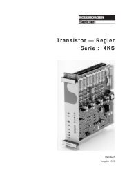
Relief Valves<br />
PILOT OPERATED, BALANCED PISTON<br />
Full Adjustment 5 Turns<br />
+ -<br />
b<br />
2<br />
Outlet<br />
Inlet<br />
1<br />
Performance Curves<br />
c<br />
a<br />
Locating<br />
Shoulder<br />
2 1<br />
<strong>Cartridge</strong> Dimensions<br />
Capacity<br />
Typical<br />
<strong>Cartridge</strong><br />
Model Code<br />
Cavity a b<br />
L<br />
c<br />
C K<br />
Installation<br />
Torque<br />
(Nm)<br />
45 L/min. RPCC – LAN T - 162A 31,0 19,1 53,6 55,1 60,7 35 - 40<br />
95 L/min. RPEC – LAN T - 10A 39,6 22,2 50,8 54,6 57,2 45 - 50<br />
200 L/min. RPGC – LAN T-3A 47,8 28,6 53,8 55,4 60,5 60 - 70<br />
380 L/min. RPIC – LAN T - 16A 62,0 31,8 62,0 62,7 68,3 200 - 215<br />
760 L/min. RPKC – LAN T-18A 79,5 41,3 71,4 74,7 77,7 465 - 500<br />
RPCC RPEC RPGC RPIC RPKC<br />
Typical Pressure Rise<br />
P = bar<br />
350<br />
300<br />
250<br />
200<br />
150<br />
100<br />
50<br />
P = bar<br />
350<br />
300<br />
250<br />
200<br />
150<br />
100<br />
50<br />
P = bar<br />
350<br />
300<br />
250<br />
200<br />
150<br />
100<br />
50<br />
0 25 50 75<br />
Flow = L/min.<br />
100<br />
0 50 100 150<br />
Flow = L/min.<br />
200<br />
0 100 200 300<br />
Flow = L/min.<br />
400<br />
0 200 400 600<br />
Flow = L/min.<br />
800<br />
0 400 800 1200<br />
Flow = L/min.<br />
■<br />
■<br />
Maximum operating pressure = 350 bar.<br />
Maximum valve leakage at 24 cSt = RPCC, RPEC: 30 cc/min. at 70 bar; RPGC: 50 cc/min. at 70 bar;<br />
RPIC: 65,5 cc/min. at 70 bar; RPKC: 80 cc/min. at 70 bar.<br />
■ Typical response time 10 ms.<br />
■ Factory pressure settings established at 15 L/min.<br />
■ Will accept maximum pressure at Port 2.<br />
■ Back pressure on the tank port (port 2) is directly additive at a 1:1 ratio to the valve setting.<br />
OPTION ORDERING INFORMATION<br />
RP ✱ C – ✱ ✱ ✱<br />
Nominal<br />
Capacity<br />
Control** Adjustment Range Seal Material<br />
C 45 L/min. L Standard Screw RPCC only: N Buna-N<br />
Adjustment A 5 - 210 bar<br />
E 95 L/min. Standard set at 70 bar V Viton<br />
C* Tamper Resistant B 5 - 105 bar<br />
G 200 L/min. Factory Set Standard set at 70 bar<br />
C 5 - 420 bar<br />
I 380 L/min. K Handknob Standard set at 70 bar<br />
with Lock Knob N 5 - 55 bar<br />
K 760 L/min. Standard set at 30 bar<br />
RPEC, Q 5 - 25 bar<br />
RPGC only: Standard set at 14 bar<br />
O Handknob with W 5 - 315 bar<br />
Panel Mount Standard set at 70 bar<br />
* Special setting required. RPEC, RPGC,<br />
Specify at time of order. RPIC, RPKC only:<br />
A 7 - 210 bar<br />
Standard set at 70 bar<br />
B 3,5 - 105 bar<br />
Standard set at 70 bar<br />
C 10,5 - 420 bar<br />
** See page 178 Standard set at 70 bar<br />
for information N 4 - 55 bar<br />
on Control Options Standard set at 28 bar<br />
Q 4 - 25 bar<br />
Customer specified Standard set at 14 bar<br />
special setting W 10,5 - 315 bar<br />
stamped on hex. Standard set at 70 bar<br />
Visit www.sunhydraulics.com for current list pricing and complete technical information on all Sun products.<br />
P = bar<br />
350<br />
300<br />
250<br />
200<br />
150<br />
100<br />
50<br />
6 Int’l <strong>Shortcut</strong> <strong>Catalogue</strong> #999-901-312<br />
P = bar<br />
350<br />
300<br />
250<br />
200<br />
150<br />
100<br />
50<br />
Consult the Sun website for<br />
our most recent and complete<br />
information on the full Corrosion<br />
Resistant line of products.<br />
1600
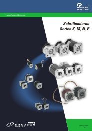
Relief Valves<br />
DIRECT ACTING AND DIRECT ACTING, NON-ADJUSTABLE<br />
Full Adjustment 5 Turns<br />
+ -<br />
L Control<br />
P = bar<br />
3 Control<br />
b<br />
2<br />
Outlet<br />
RDBA RDDA RDFA RDHA RDJA<br />
350<br />
300<br />
250<br />
200<br />
150<br />
100<br />
50<br />
Inlet<br />
1<br />
c<br />
a<br />
Performance Curves<br />
Locating<br />
Shoulder<br />
P = bar<br />
350<br />
300<br />
250<br />
200<br />
150<br />
100<br />
50<br />
Visit www.sunhydraulics.com for current list pricing and complete technical information on all Sun products.<br />
Int’l <strong>Shortcut</strong> <strong>Catalogue</strong> #999-901-312 7<br />
2<br />
RD*A<br />
1<br />
<strong>Cartridge</strong> Dimensions<br />
Capacity<br />
Typical<br />
<strong>Cartridge</strong><br />
Model Code<br />
Cavity a b<br />
L<br />
c<br />
C<br />
Installation<br />
Torque<br />
(Nm)<br />
45 L/min. RDBA – LAN T - 162A 31,0 19,1 53,6 56,4 35 - 40<br />
95 L/min. RDDA – LAN T - 10A 39,6 22,2 59,2 63,2 45 - 50<br />
200 L/min. RDFA – LAN T-3A 47,8 28,6 63,5 65,0 60 - 70<br />
380 L/min. RDHA – LAN T - 16A 62,0 31,8 82,6 84,1 200 - 215<br />
760 L/min. RDJA – LAN T - 18A 79,5 41,3 100,0 103,4 465 - 500<br />
P = bar<br />
Typical Pressure Rise<br />
350<br />
300<br />
250<br />
200<br />
150<br />
100<br />
50<br />
0 10 20 30 40 50<br />
0 25 50 75 100<br />
0 50 100 150 200<br />
0 100 200 300 400<br />
0 200 400 600 800<br />
Flow = L/min.<br />
Flow = L/min.<br />
Flow = L/min.<br />
Flow = L/min.<br />
Flow = L/min.<br />
■ Maximum operating pressure = 350 bar.<br />
■ Maximum valve leakage at reseat = 0,7 cc/min.<br />
■ Typical response time 2 ms.<br />
■ Factory pressure settings established at 15 L/min.<br />
■ Will accept maximum pressure at Port 2.<br />
■ Back pressure on the tank port (port 2) is directly additive at a 1:1 ratio to the valve setting.<br />
■ The seals on the adjust screw are exposed to system pressure which means this valve can only be adjusted when<br />
the pressure is removed. The setting procedure is; check the setting, remove the pressure, adjust the valve, check the new setting.<br />
■ Reseat exceeds 90% of cracking pressure.<br />
■ Select a spring range where the desired relief setting is approximately mid-range between the minimum and maximum pressure<br />
to ensure maximum valve repeatability.<br />
OPTION ORDERING INFORMATION<br />
P = bar<br />
350<br />
300<br />
250<br />
200<br />
150<br />
100<br />
50<br />
RD ✱ A – ✱ ✱ ✱<br />
Nominal<br />
Capacity<br />
Control** Adjustment Range Seal Material<br />
B 45 L/min. L Standard Screw A 35 - 210 bar N Buna-N<br />
Adjustment Standard set at 70 bar<br />
D 95 L/min. B 20 - 105 bar V Viton<br />
C*Tamper Resistant Standard set at 70 bar<br />
F 200 L/min. Factory Set C 70 - 420 bar<br />
Standard set at 70 bar<br />
H 380 L/min. RDDA, RDFA only: D 14 - 55 bar<br />
3* Non-Adjustable Standard set at 28 bar<br />
J 760 L/min. E 10 - 28 bar<br />
* Special setting required. Standard set at 14 bar<br />
Specify at time of order.<br />
** See page 178<br />
S 3,5 - 14 bar<br />
Standard set at 7 bar<br />
W 55 - 315 bar<br />
Standard set at 70 bar<br />
U.S. Patent #4,742,846<br />
European Patent Pending<br />
for information<br />
on Control Options<br />
Customer specified<br />
special setting<br />
stamped on hex.<br />
RDDA-3, RDFA-3<br />
only available with<br />
A, C, D ranges.<br />
Consult the Sun website<br />
for our most recent and<br />
complete information<br />
on the full Corrosion<br />
Resistant line of products.<br />
P = bar<br />
350<br />
300<br />
250<br />
200<br />
150<br />
100<br />
50
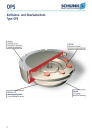
Relief Valves<br />
DIRECT ACTING, CE MARKED<br />
b<br />
Full Adjustment 5 Turns<br />
+ -<br />
2<br />
Outlet<br />
1<br />
Inlet<br />
Performance Curves<br />
c<br />
a<br />
Locating<br />
Shoulder<br />
Nominal<br />
Capacity<br />
RDDT RDFT<br />
Permissible Operating Range<br />
■ Maximum valve leakage at reseat = 0,7 cc/min.<br />
■ Reseat = > 90% of set pressure.<br />
■ Typical response time 2 ms.<br />
■ Standard settings for preset valves: 100, 140, 160, 210, 250, and 330 bar.<br />
■ Pressure setting from 100 bar up to 422 bar are approved and certified by TüV.<br />
■ Will accept maximum pressure at port 2; suitable for use in cross-port relief circuits.<br />
■ Back pressure on the tank port (port 2) is additive to the valve setting at a 1:1 ratio.<br />
RD ✱ T – ✱ ✱ ✱<br />
Control Adjustment Range Seal Material<br />
D 75 L/min. Q*Capped and RDDT: N Buna-N<br />
Lockwire A 100 - 210 bar<br />
V Viton<br />
F 79 L/min. * Special setting required.<br />
Specify at time of order.<br />
C 315 - 422 bar<br />
W 211 - 314 bar<br />
U.S. Patent #4,742,846<br />
2<br />
Capacity<br />
75 L/min.<br />
79 L/min.<br />
OPTION ORDERING INFORMATION<br />
1<br />
Typical<br />
<strong>Cartridge</strong><br />
Model Code<br />
The CE marked valve is a safety valve that meets the requirements of the European<br />
Directive for Pressurized Devices (PED) 97/23/EC.<br />
Each delivery contains a TüV approval, which is a certification of the excess<br />
operating pressure and the approved flow, an EC declaration of conformity, and an<br />
instructional manual. See Sun website for further information.<br />
RDFT:<br />
A 106 - 209 bar<br />
B 60 - 105 bar<br />
C 210 - 420 bar<br />
<strong>Cartridge</strong> Dimensions<br />
Cavity a b c<br />
Visit www.sunhydraulics.com for current list pricing and complete technical information on all Sun products.<br />
Installation<br />
Torque<br />
(Nm)<br />
RDDT – QAN T-10A 40,0 mm 22,2 mm 65,0 mm 45 - 50<br />
RDFT – QAN T - 3A 47,8 mm 28,6 mm 70,4 mm 60 - 70<br />
450<br />
450<br />
400<br />
350<br />
300<br />
250<br />
200<br />
150<br />
Permissible<br />
Range *<br />
400<br />
350<br />
300<br />
250<br />
200<br />
150<br />
100<br />
Permissible<br />
Range<br />
100<br />
0 20 40 60 80<br />
50<br />
0 20 40 60 80 100<br />
Flow = L/min.<br />
Flow = L/min.<br />
Maximum Approved Flow<br />
*Approved flow at 210 bar is 75 L/min.<br />
Maximum Approved Flow<br />
P = bar<br />
P = bar<br />
8 Int’l <strong>Shortcut</strong> <strong>Catalogue</strong> #999-901-312
Relief Valves<br />
DIRECT ACTING, PILOT CAPACITY<br />
Full Adjustment 5 Turns<br />
+ -<br />
b<br />
2<br />
Outlet<br />
Inlet<br />
Performance Curves<br />
1<br />
c<br />
a<br />
Locating<br />
Shoulder<br />
RBAC RBAA RBAE<br />
P = bar<br />
350<br />
300<br />
250<br />
200<br />
150<br />
100<br />
50<br />
Visit www.sunhydraulics.com for current list pricing and complete technical information on all Sun products.<br />
Int’l <strong>Shortcut</strong> <strong>Catalogue</strong> #999-901-312 9<br />
2<br />
1<br />
<strong>Cartridge</strong> Dimensions<br />
Capacity<br />
Typical<br />
<strong>Cartridge</strong><br />
Model Code<br />
Cavity a b<br />
L C<br />
c<br />
K O<br />
Installation<br />
Torque<br />
(Nm)<br />
1 L/min. RBAC – LAN T - 10A 39,6 22,2 50,8 54,6 57,2 58,0 45 - 50<br />
2 L/min. RBAA – LAN T - 3A 47,8 28,6 53,8 55,4 60,5 61,0 60 - 70<br />
10 L/min. RBAE – LAN T-8A 19,0 22,2 60,5 62,7 67,6 67,6 35 - 40<br />
0 0,32 0,64 0,96 1,28 1,6<br />
Flow = L/min.<br />
Typical Pressure Rise<br />
■ Maximum operating pressure = 350 bar.<br />
■ Maximum valve leakage at reseat at 24 cSt = RBAC, RBAA: 0,4 cc/min.; RBAE: 1 cc/min.<br />
■ Typical response time 2 ms.<br />
■ Back pressure on the tank port (port 2) is directly additive to the pressure setting<br />
at port 1 (inlet) at a 1:1 ratio to the valve setting.<br />
■ RBAE: Utilizes the Sun T-8A, 2 port cavity making it the ideal choice to use in conjunction with Sun’s<br />
main stage pilot or vent-to-operate cartridges. Separate pilot lines are eliminated and only one cavity<br />
needs to be machined to accommodate both the control and primary function. Note: All 2-position,<br />
2-way pilot stage control cartridges utilize the same cavity and are physically interchangeable.<br />
Functionality is the only consideration.<br />
OPTION ORDERING INFORMATION<br />
RB A ✱ – ✱ ✱ ✱<br />
Nominal<br />
Capacity<br />
Control** Adjustment Range Seal Material<br />
AC 1 L/min. L Standard Screw A 1,7 - 210 bar N Buna-N<br />
Adjustment Standard set at 70 bar<br />
V Viton<br />
AA 2 L/min. C*Tamper Resistant B 1,7 - 105 bar<br />
with Lock Knob Standard set at 70 bar<br />
AE 10 L/min. K Handknob C 1,7 - 420 bar<br />
Factory Set Standard set at 70 bar<br />
P = bar<br />
O Handknob with D 1,7 - 55 bar<br />
Panel Mount Standard set at 25 bar<br />
* Special setting required. E 1,7 - 25 bar<br />
Specify at time of order. Standard set at 14 bar<br />
** See page 178 W 1,7 - 315 bar<br />
for information Standard set at 70 bar<br />
on Control Options<br />
Customer specified special<br />
setting stamped on hex.<br />
350<br />
300<br />
250<br />
200<br />
150<br />
100<br />
50<br />
0 0,5 1,0 1,5 2,0 2,5<br />
Flow = L/min.<br />
P = bar<br />
400<br />
300<br />
200<br />
100<br />
0 2 4 6 8 10<br />
Flow = L/min.<br />
Consult the Sun website for<br />
our most recent and complete<br />
information on the full Corrosion<br />
Resistant line of products.
Relief Valves<br />
PILOT OPERATED, BALANCED POPPET<br />
Full Adjustment 5 Turns<br />
+ -<br />
b<br />
2<br />
Outlet<br />
Inlet 1<br />
Performance Curves<br />
P = bar<br />
2 1<br />
<strong>Cartridge</strong> Dimensions<br />
Capacity<br />
Typical<br />
<strong>Cartridge</strong><br />
Model Code<br />
Cavity a b<br />
L<br />
c<br />
C K<br />
Installation<br />
Torque<br />
(Nm)<br />
95 L/min. RPES – LAN T-10A 39,6 22,2 50,8 54,6 57,2 40 - 50<br />
200 L/min. RPGS – LAN T - 3A 47,8 28,6 53,8 55,4 60,5 60 - 70<br />
380 L/min. RPIS – LAN T-16A 62,0 31,8 62,0 62,7 68,3 200 - 215<br />
760 L/min. RPKS – LAN T - 18A 79,5 41,3 71,4 74,7 77,7 465 - 500<br />
RPES RPGS RPIS RPKS<br />
250<br />
200<br />
150<br />
100<br />
50<br />
0<br />
c<br />
a<br />
Locating<br />
Shoulder<br />
25 50 75<br />
Flow = L/min.<br />
95<br />
P = bar<br />
250<br />
200<br />
150<br />
100<br />
50<br />
0<br />
Typical Pressure Rise<br />
50 100 150<br />
Flow = L/min.<br />
■ Maximum operating pressure = 350 bar.<br />
■ Maximum valve leakage at reseat = RPES: 0,7 cc/min.; RPGS, RPIS, RPKS: 2,1 cc/min.<br />
■ Typical response time 2 ms.<br />
■ Factory pressure settings established at 15 L/min.<br />
■ Will accept maximum pressure at port 2; suitable for use in cross-port relief circuits.<br />
■ Back pressure on the tank port (port 2) is directly additive at a 1:1 ratio to the valve setting.<br />
OPTION ORDERING INFORMATION<br />
RP ✱ S – ✱ ✱ ✱<br />
Nominal<br />
Capacity<br />
Control** Adjustment Range Seal Material<br />
E 95 L/min. C* Tamper Resistant A 7 - 210 bar N Buna-N<br />
Factory Set Standard set at 70 bar<br />
G 200 L/min.<br />
K Handknob B 3,5 - 105 bar V Viton<br />
I 380 L/min. with Lock Knob Standard set at 70 bar<br />
K 760 L/ min. L Standard Screw C 10,5 - 420 bar<br />
Adjustment Standard set at 70 bar<br />
* Special setting required. N 4 - 55 bar<br />
Specify at time of order. Standard set at 30 bar<br />
Q 4 - 25 bar<br />
Standard set at 14 bar<br />
RPES, RPGS only:<br />
W 7 - 315 bar<br />
Standard set at 70 bar<br />
** See page 178 RPIS, RPKS only:<br />
for information W 10,5 - 315 bar<br />
on Control Options Standard set at 70 bar<br />
Customer specified special<br />
setting stamped on hex.<br />
200<br />
Visit www.sunhydraulics.com for current list pricing and complete technical information on all Sun products.<br />
P = bar<br />
250<br />
200<br />
150<br />
100<br />
50<br />
0<br />
100 200 300<br />
Flow = L/min.<br />
400<br />
P = bar<br />
250<br />
200<br />
150<br />
100<br />
50<br />
0 200 400 600<br />
Flow = L/min.<br />
10 Int’l <strong>Shortcut</strong> <strong>Catalogue</strong> #999-901-312<br />
800<br />
Consult the Sun website for<br />
our most recent and complete<br />
information on the full Corrosion<br />
Resistant line of products.
Relief Valves<br />
PILOT OPERATED, BALANCED POPPET, SOFT<br />
Full Adjustment 4.5 Turns<br />
+ -<br />
b<br />
2<br />
Outlet<br />
1<br />
Inlet<br />
c<br />
a<br />
Locating<br />
Shoulder<br />
2 1<br />
Simplified Symbol Complex Symbol<br />
Capacity<br />
Typical<br />
<strong>Cartridge</strong><br />
Model Code<br />
Performance Curves<br />
RPET RPGT RPIT RPKT<br />
P = bar<br />
P = bar<br />
400<br />
300<br />
200<br />
100<br />
400<br />
300<br />
200<br />
100<br />
0 25 50 75<br />
Flow = L/min.<br />
0 250 500<br />
Time/ms.<br />
750 1000<br />
■ Maximum operating pressure = 350 bar.<br />
■ Control pilot flow = 0,16 to 0,41 L/min.<br />
■ Pressure Ramp Up Time = RPET: 200 ms., RPGT: 300 ms., RPIT: 400 ms., RPIC: 500 ms.<br />
■ Factory pressure settings established at 15 L/min.<br />
■ Will accept maximum pressure at Port 2.<br />
■ When pressure at the inlet (port 1) exceeds the threshold setting, the valve opens to tank (port 2). The<br />
pilot section moves forward at a steady rate, increasing the setting by compressing the pilot spring.<br />
Maximum setting is achieved when the pilot section reaches a mechanical stop.<br />
Visit www.sunhydraulics.com for current list pricing and complete technical information on all Sun products.<br />
Int’l <strong>Shortcut</strong> <strong>Catalogue</strong> #999-901-312 11<br />
RP ✱ T – ✱ ✱ ✱<br />
Nominal<br />
Capacity<br />
Control** Adjustment Range Seal Material<br />
E 95 L/min. C*Tamper Resistant A 140 - 210 bar N Buna-N<br />
Factory Set Standard set at 140 bar<br />
G 200 L/min. V Viton<br />
L Standard Screw C 315 - 420 bar<br />
I 380 L/min. Adjustment Standard set at 315 bar<br />
K 760 L/min. * Special setting required. W 210-315 bar<br />
Specify at time of order. Standard set at 210 bar<br />
** See page 178<br />
for information<br />
on Control Options<br />
Patent: Customer specified special<br />
U.S. #6,039,070. setting stamped on hex.<br />
2<br />
1<br />
<strong>Cartridge</strong> Dimensions<br />
Cavity a b<br />
L<br />
c<br />
C<br />
Installation<br />
Torque<br />
(Nm)<br />
95 L/min. RPET - LAN T-10A 39,6 22,8 79,5 85,1 40 - 50<br />
200 L/min. RPGT - LAN T - 3A 47,8 28,6 85,9 88,1 60 - 70<br />
380 L/min. RPIT - LAN T-16A 61,7 31,8 86,9 89,2 200 - 215<br />
760 L/min. RPKT - LAN T - 18A 79,2 41,3 88,4 85,3 465 - 500<br />
100<br />
P = bar<br />
P = bar<br />
400<br />
300<br />
200<br />
100<br />
400<br />
300<br />
200<br />
100<br />
OPTION ORDERING INFORMATION<br />
0<br />
Pressure Differential vs. Flow<br />
50 100 150<br />
Flow = L/min.<br />
0 200 400 600 800<br />
Time/ms.<br />
200<br />
1000<br />
P = bar<br />
P = bar<br />
400<br />
300<br />
200<br />
100<br />
Time vs. Pressure<br />
400<br />
300<br />
200<br />
100<br />
0 100 200 300<br />
Flow = L/min.<br />
400<br />
0 250 500<br />
Time/ms.<br />
750 1000<br />
P = bar<br />
P = bar<br />
400<br />
300<br />
200<br />
100<br />
400<br />
300<br />
200<br />
100<br />
0 200 400 600<br />
Flow = L/min.<br />
800<br />
0 250 500<br />
Time/ms.<br />
750 1000
Relief Valves<br />
PILOT OPERATED, KICK-DOWN, BALANCED PISTON<br />
Full Adjustment 5 Turns<br />
+ -<br />
b<br />
2<br />
Outlet<br />
Inlet<br />
1<br />
c<br />
a<br />
Nominal<br />
Locating<br />
Shoulder<br />
P = bar<br />
2 1<br />
<strong>Cartridge</strong> Dimensions<br />
Capacity<br />
Typical<br />
<strong>Cartridge</strong><br />
Model Code<br />
Cavity a b<br />
L<br />
c<br />
C K<br />
Installation<br />
Torque<br />
(Nm)<br />
45 L/min. RQCB – LAN T - 162A 31,0 19,1 53,6 55,1 58,7 35 - 40<br />
95 L/min. RQEB – LAN T - 10A 39,6 22,2 50,8 54,6 57,2 45 - 50<br />
200 L/min. RQGB– LAN T-3A 47,8 28,6 53,8 55,4 60,5 60 - 70<br />
380 L/min. RQIB – LAN T - 16A 62,0 31,8 62,0 62,7 68,3 200 - 215<br />
760 L/min. RQKB – LAN T - 18A 79,5 41,3 71,4 74,7 77,7 465 - 500<br />
Performance Curves<br />
RQCB RQEB RQGB RQIB RQKB<br />
P = bar<br />
20<br />
15<br />
10<br />
5<br />
A,B,C,N,Q,W<br />
0 20 40 60<br />
Flow = L/min.<br />
Unloaded Pressure Drop<br />
20<br />
20<br />
15<br />
15<br />
10<br />
C & W<br />
10<br />
C & W<br />
5<br />
A<br />
B,N,Q<br />
5 A<br />
B,N,Q<br />
0 25 50 75 100<br />
0 50 100 150 200<br />
Flow = L/min.<br />
Flow = L/min.<br />
P = bar<br />
■ Maximum operating pressure = 350 bar.<br />
■ Maximum valve leakage at 24 cSt = RQCB, RQEB: 30 cc/min. at 70 bar;<br />
RQGB: 49,2 cc/min. at 70 bar; RQIB: 65,5 cc/min. at 70 bar; RQKB: 81,9 cc/min. at 70 bar.<br />
■ Typical response time 25 ms.<br />
■ Factory pressure settings established at kick down point.<br />
■ Flow through cartridge must cease to reset valve.<br />
■ Back pressure on the tank port (port 2) is directly additive to the valve setting at a 1:1 ratio.<br />
OPTION ORDERING INFORMATION<br />
RQ ✱ B – ✱ ✱ ✱<br />
Control** Adjustment Range Seal Material<br />
Capacity<br />
C 45 L/min. L Standard Screw RQCB only: N Buna-N<br />
Adjustment A 5 - 210 bar<br />
E 95 L/min. Standard set at 70 bar V Viton<br />
C* Tamper Resistant B 5 - 105 bar<br />
G 200 L/min. Factory Set Standard set at 70 bar<br />
C 5 - 420 bar<br />
I 380 L/min. K Handknob Standard set at 70 bar<br />
with Lock Knob N 5 - 55 bar<br />
K 760 L/min. Standard set at 25 bar<br />
* Special setting required. Q 5 - 25 bar<br />
Specify at time of order. Standard set at 14 bar<br />
W 5 - 315 bar<br />
Standard set at 70 bar<br />
RQEB, RQGB,<br />
RQIB, RQKB only:<br />
A 7 - 210 bar<br />
Standard set at 70 bar<br />
B 3,5 - 105 bar<br />
Standard set at 70 bar<br />
C 10,5 - 420 bar<br />
Standard set at 70 bar<br />
** See page 178 Q 4 - 25 bar<br />
for information Standard set at 14 bar<br />
on Control Options W 10,5 - 315 bar<br />
Standard set at 70 bar<br />
Customer specified RQEB, RQGB, only:<br />
special setting N 4 - 55 bar<br />
stamped on hex. Standard set at 25 bar<br />
0 100 200 300 400<br />
Flow = L/min.<br />
Visit www.sunhydraulics.com for current list pricing and complete technical information on all Sun products.<br />
P = bar<br />
20<br />
15<br />
10<br />
5<br />
A<br />
C & W<br />
B,N,Q<br />
0 200 400 600 800<br />
Flow = L/min.<br />
12 Int’l <strong>Shortcut</strong> <strong>Catalogue</strong> #999-901-312<br />
P = bar<br />
20<br />
15<br />
10<br />
5<br />
C & W<br />
A<br />
B,N,Q<br />
Consult the Sun website for<br />
our most recent and complete<br />
information on the full Corrosion<br />
Resistant line of products.
Relief Valves<br />
PILOT OPERATED, BALANCED PISTON, AIR CONTROLLED<br />
b<br />
2<br />
Outlet<br />
Air Pilot Port<br />
Inlet<br />
Performance Curves<br />
1<br />
c<br />
a<br />
Locating<br />
Shoulder<br />
RPGD RPID RPKD<br />
P = bar<br />
200<br />
150<br />
100<br />
50<br />
Visit www.sunhydraulics.com for current list pricing and complete technical information on all Sun products.<br />
Int’l <strong>Shortcut</strong> <strong>Catalogue</strong> #999-901-312 13<br />
2<br />
Air Pilot<br />
1<br />
<strong>Cartridge</strong> Dimensions<br />
Capacity<br />
Typical<br />
<strong>Cartridge</strong><br />
Model Code<br />
Cavity a b<br />
A<br />
c<br />
B<br />
Installation<br />
Torque<br />
(Nm)<br />
200 L/min. RPGD – ABN T-3A 47,8 28,6 33,3 — 60 - 70<br />
380 L/min. RPID – BBN T - 16A 62,0 31,8 — 41,1 200 - 215<br />
760 L/min. RPKD – BBN T-18A 79,5 41,3 — 50,8 465 - 500<br />
0 50 100 150 200<br />
Flow = L/min.<br />
P = bar<br />
Typical Pressure Rise<br />
200<br />
150<br />
100<br />
50<br />
■ Pilot ratio, air to hydraulic = 20:1.<br />
■ Maximum air pressure = 10,5 bar.<br />
■ Maximum operating pressure = 140 bar.<br />
■ Maximum valve leakage at 24 cSt = RPGD: 50 cc/min. at 70 bar; RPID: 65 cc/min. at 70 bar;<br />
RPKD: 80 cc/min. at 70 bar.<br />
■ Typical response time 10 ms.<br />
■ Will accept maximum pressure at Port 2; suitable for use in cross-port relief circuits.<br />
OPTION ORDERING INFORMATION<br />
RP ✱ D – ✱ ✱ ✱<br />
Nominal<br />
Capacity<br />
Control Adjustment Range Seal Material<br />
RPGD only:<br />
RPGD only:<br />
G 200 L/min. A External<br />
1/4" NPTF<br />
B 3,5 - 105 bar N Buna-N<br />
I 380 L/min. Pilot Port at<br />
end of <strong>Cartridge</strong>*<br />
I 1 - 70 bar V Viton<br />
K 760 L/min. RPID, RPKD only:<br />
RPID, RPKD only:<br />
B External SAE-4<br />
B 3,5 - 105 bar<br />
Pilot Port at RPKD only:<br />
end of <strong>Cartridge</strong>* J 2 - 105 bar<br />
* Maximum air pilot pressure<br />
should not exceed 10 bar.<br />
0 100 200 300 400<br />
Flow = L/min.<br />
P = bar<br />
200<br />
150<br />
100<br />
50<br />
0 200 400 600 800<br />
Flow = L/min.
Relief Valves, Electro-Proportional<br />
ELECTRO-PROPORTIONAL, PILOT CAPACITY<br />
b<br />
2<br />
Outlet<br />
d<br />
Inlet 1<br />
Locating<br />
Shoulder<br />
Performance Curves<br />
2 1<br />
Capacity<br />
RBAP<br />
■ Maximum operating pressure = 350 bar.<br />
■ Maximum valve leakage at reseat = 25 cc/min.<br />
■ Hysteresis with dither
Relief Valves, Electro-Proportional<br />
ELECTRO-PROPORTIONAL, PILOT CAPACITY, HIGH PRESSURE SETTING<br />
WITH NO COMMAND, INVERSE FUNCTION<br />
b<br />
2<br />
Outlet<br />
Inlet<br />
Performance Curves<br />
d<br />
1<br />
c<br />
a<br />
Locating<br />
Shoulder<br />
2 1<br />
Capacity<br />
Typical<br />
<strong>Cartridge</strong><br />
Model Code<br />
■ Maximum operating pressure = 350 bar.<br />
■ Maximum valve leakage at reseat = 25 cc/min.<br />
■ Hysteresis with dither
Relief Valves, Electro-Proportional<br />
PILOT OPERATED, BALANCED PISTON, MAIN STAGE WITH INTEGRAL<br />
T-8A CONTROL CAVITY<br />
b<br />
2<br />
Outlet<br />
T-8A Cavity 2<br />
1<br />
Inlet 1<br />
Performance Curves<br />
c<br />
a<br />
Locating<br />
Shoulder<br />
T-8A<br />
Cav<br />
Capacity<br />
Typical<br />
<strong>Cartridge</strong><br />
Model Code<br />
The -8 control option allows a pilot control valve to be incorporated directly<br />
into the end of the relief cartridge via the T-8A cavity. These pilot control<br />
cartridges are sold separately and include electro-proportional, solenoid, air<br />
pilot, and hydraulic pilot operation. See Pilot Control <strong>Cartridge</strong>s on page 141.<br />
RPEC-8 RPGC-8 RPIC-8 RPKC-8<br />
P = bar<br />
P = bar<br />
400<br />
300<br />
200<br />
100<br />
0<br />
250<br />
200<br />
150<br />
100<br />
50<br />
0<br />
20 40 60 80<br />
Flow = L/min.<br />
20 40 60 80<br />
Command (%)<br />
Pressure vs. Flow with T-8A Pilot Stage Installed<br />
■ Maximum operating pressure = 350 bar.<br />
■ Control pilot flow = RPEC-8: 0,11 to 0,16 L/min.; RPGC-8: 0,16 to 0,25 L/min.;<br />
RPIC-8, RPKC-8: 0,25 to 0,33 L/min.<br />
■ Main stage leakage at 24 cSt = RPEC-8: 50 cc/min. at 70 bar; RPGC-8: 50 cc/min. at 70 bar;<br />
RPIC-8: 65 cc/min. at 70 bar; RPKC-8: 80 cc/min. at 70 bar.<br />
■ Will accept maximum pressure at Port 2; suitable for use in cross-port relief circuits.<br />
■ Back pressure on the tank port (port 2) is directly additive to the valve setting at a 1:1 ratio.<br />
■ With the -8 control option, the main stage valve should first be installed to the correct torque value.<br />
The T-8A pilot control valve should then be installed into the main stage valve to its required torque value.<br />
RP ✱ C – 8 ✱✱<br />
<strong>Cartridge</strong> Dimensions<br />
Cavity a b c<br />
Nominal<br />
Capacity<br />
Control<br />
Minimum Control<br />
Pressure<br />
Seal Material<br />
E 95 L/min. 8 T-8A Cavity in<br />
hex body for<br />
D 1,7 bar N Buna-N<br />
G 200 L/min. pilot operation W 7 bar V Viton<br />
I 380 L/min.<br />
Pilot valve to<br />
be ordered<br />
K 760 L/min.<br />
separately<br />
Visit www.sunhydraulics.com for current list pricing and complete technical information on all Sun products.<br />
Installation<br />
Torque<br />
(Nm)<br />
95 L/min. RPEC – 8WN T-10A 39,6 22,2 19,0 45 - 50<br />
200 L/min. RPGC – 8WN T - 3A 47,8 28,6 17,5 60 - 70<br />
380 L/min. RPIC – 8WN T-16A 62,0 31,8 24,6 200 - 215<br />
760 L/min. RPKC – 8WN T - 18A 79,5 41,3 30,2 465 - 500<br />
P = bar<br />
400<br />
300<br />
200<br />
100<br />
P = bar<br />
100 0 40 80 120 160 200 0 80 160 240 320 400 0 160 320 480 640 800<br />
Flow = L/min.<br />
Flow = L/min.<br />
Flow = L/min.<br />
Pressure vs. Command with T-8A Pilot Stage (RBAP-MAN) Installed<br />
P = bar<br />
250<br />
200<br />
150<br />
100<br />
50<br />
100 0 20 40 60 80<br />
Command (%)<br />
OPTION ORDERING INFORMATION<br />
P = bar<br />
400<br />
300<br />
200<br />
100<br />
250<br />
200<br />
150<br />
100<br />
50<br />
100 0 20 40 60 80<br />
Command (%)<br />
100<br />
P = bar<br />
P = bar<br />
400<br />
300<br />
200<br />
100<br />
250<br />
200<br />
150<br />
100<br />
50<br />
0<br />
20 40 60 80<br />
Command (%)<br />
16 Int’l <strong>Shortcut</strong> <strong>Catalogue</strong> #999-901-312<br />
100
Relief Valves, Electro-Proportional<br />
PILOT OPERATED, BALANCED POPPET, MAIN STAGE WITH INTEGRAL<br />
T-8A CONTROL CAVITY<br />
b<br />
2<br />
Outlet<br />
T-8A Cavity<br />
Inlet 1<br />
Performance Curves<br />
c<br />
a<br />
Locating<br />
Shoulder<br />
Capacity<br />
Typical<br />
<strong>Cartridge</strong><br />
Model Code<br />
RPES-8 RPGS-8 RPIS-8 RPKS-8<br />
P = bar<br />
P = bar<br />
250<br />
200<br />
150<br />
100<br />
50<br />
250<br />
200<br />
150<br />
100<br />
50<br />
0<br />
0<br />
25 50 75<br />
Flow = L/min.<br />
20 40 60 80<br />
Command (%)<br />
Visit www.sunhydraulics.com for current list pricing and complete technical information on all Sun products.<br />
Int’l <strong>Shortcut</strong> <strong>Catalogue</strong> #999-901-312 17<br />
2<br />
T-8A<br />
Cav<br />
1<br />
The -8 control option allows a pilot control valve to be incorporated directly<br />
into the end of the relief cartridge via the T-8A cavity. These pilot control<br />
cartridges are sold separately and include electro-proportional, solenoid, air<br />
pilot, and hydraulic pilot operation. See Pilot Control <strong>Cartridge</strong>s on page 141.<br />
Pressure Differential vs. Flow with T-8A Pilot Stage Installed<br />
■ Maximum operating pressure = 350 bar.<br />
■ Control pilot flow = RPES-8: 0,16 to 0,41 L/min.; RPGS-8: 0,16 to 0,25 L/min.;<br />
RPIS-8, RPKS-8: 0,25 to 0,33 L/min.<br />
■ Main stage leakage at 10% reseat = 0,7 cc/min.<br />
■ Typical response time 2 ms.<br />
■ Will accept maximum pressure at Port 2; suitable for use in cross-port relief circuits.<br />
■ Back pressure on the tank port (port 2) is directly additive to the valve setting at a 1:1 ratio.<br />
■ With the -8 control option, the main stage valve should first be installed to the correct torque value.<br />
The T-8A pilot control valve should then be installed into the main stage valve to its required torque value.<br />
RP ✱ S – 8 ✱✱<br />
<strong>Cartridge</strong> Dimensions<br />
Cavity a b c<br />
Nominal<br />
Capacity<br />
Control<br />
Minimum Control<br />
Pressure<br />
Seal Material<br />
E 95 L/min. 8 T-8A Cavity in<br />
hex body for<br />
B 3,5 bar N Buna-N<br />
G 200 L/min. pilot operation W 7 bar V Viton<br />
I<br />
K<br />
380 L/min.<br />
760 L/min.<br />
Pilot valve to<br />
be ordered<br />
separately<br />
RPES-8 only:<br />
D 1,7 bar<br />
Installation<br />
Torque<br />
(Nm)<br />
95 L/min. RPES – 8WN T - 10A 39,6 22,2 19,0 40 - 50<br />
200 L/min. RPGS – 8WN T - 3A 47,8 28,6 17,5 60 - 70<br />
380 L/min. RPIS – 8WN T - 16A 62,0 31,8 24,6 200 - 215<br />
760 L/min. RPKS – 8WN T - 18A 79,2 41,3 30,0 465 - 500<br />
P = bar<br />
Pressure vs. Command with T-8A Pilot Stage (RBAP-MAN) Installed<br />
P = bar<br />
250<br />
200<br />
150<br />
100<br />
50<br />
250<br />
200<br />
150<br />
100<br />
50<br />
0<br />
50 100 150<br />
Flow = L/min.<br />
100 0 20 40 60 80<br />
Command (%)<br />
OPTION ORDERING INFORMATION<br />
100<br />
200<br />
P = bar<br />
P = bar<br />
250<br />
200<br />
150<br />
100<br />
50<br />
250<br />
200<br />
150<br />
100<br />
50<br />
0<br />
100 200 300<br />
Flow = L/min.<br />
100 0 20 40 60 80<br />
Command (%)<br />
400<br />
100<br />
P = bar<br />
P = bar<br />
250<br />
200<br />
150<br />
100<br />
50<br />
250<br />
200<br />
150<br />
100<br />
50<br />
0 200 400 600<br />
Flow = L/min.<br />
0<br />
20 40 60 80<br />
Command (%)<br />
800<br />
100
Relief Valves<br />
PILOT OPERATED, BALANCED PISTON, VENTABLE<br />
2 1<br />
3<br />
<strong>Cartridge</strong> Dimensions<br />
Capacity<br />
Typical<br />
<strong>Cartridge</strong><br />
Model Code<br />
Cavity a b<br />
L C<br />
c<br />
K O<br />
Installation<br />
Torque<br />
(Nm)<br />
30 L/min. RVBA – LAN T - 163A 31,0 19,1 64,8 66,8 70,4 71,0 35 - 40<br />
60 L/min. RVCA – LAN T - 11A 35,1 22,2 63,5 67,3 70,0 70,0 45 - 50<br />
120 L/min. RVEA – LAN T-2A 34,8 28,6 71,4 73,2 77,7 — 60 - 70<br />
240 L/min. RVGA – LAN T - 17A 46,0 31,8 83,3 84,1 89,7 — 200 - 215<br />
480 L/min. RVIA – LAN T-19A 63,5 41,3 100,0 103,9 106,4 — 465 - 500<br />
Performance Curves<br />
RVBA RVCA RVEA RVGA RVIA<br />
P = bar<br />
Full Adjustment 5 Turns<br />
+ -<br />
b<br />
3<br />
Vent<br />
2<br />
Outlet<br />
350<br />
300<br />
250<br />
200<br />
150<br />
100<br />
50<br />
0<br />
Inlet 1<br />
c<br />
a<br />
10 20 30 40<br />
Flow = L/min.<br />
Locating<br />
Shoulder<br />
50<br />
P = bar<br />
350<br />
300<br />
250<br />
200<br />
150<br />
100<br />
50<br />
0 25 50 75 100<br />
Flow = L/min.<br />
P = bar<br />
350<br />
300<br />
250<br />
200<br />
150<br />
100<br />
50<br />
0<br />
50 100 150<br />
Flow = L/min.<br />
■ Maximum operating pressure = 350 bar.<br />
■ Maximum valve leakage at 24 cSt = RVBA, RVCA: 30 cc/min. at 70 bar; RVEA: 50 cc/min. at 70 bar;<br />
RVGA: 65 cc/min. at 70 bar; RVIA: 80 cc/min. at 70 bar.<br />
■ Typical response time 10 ms.<br />
■ Control pilot flow = RVBA, RVCA: 0,11 to 0,16 L/min.; RVEA: 0,16 to 0,25 L/min.; RVGA, RVIA: 0,25 to 0,33 L/min.<br />
■ Factory pressure setting established at 15 L/min.<br />
■ A remote pilot relief on port 3 (vent) will control the valve below its own setting.<br />
■ Will accept maximum pressure at port 2; suitable for use in cross-port relief circuits. If used in cross-port relief circuits, consider<br />
spool leakage.<br />
■ Back pressure on the tank port (port 2) is directly additive to the valve setting at a 1:1 ratio.<br />
OPTION ORDERING INFORMATION<br />
Typical Pressure Rise<br />
RV ✱ A – ✱ ✱ ✱<br />
Nominal<br />
Capacity<br />
Control** Adjustment Range Seal Material<br />
B 30 L/min. L Standard Screw RVBA only: N Buna-N<br />
Adjustment A 5 - 210 bar<br />
C 60 L/min. Standard set at 70 bar V Viton<br />
C*Tamper Resistant B 5 - 105 bar<br />
E 120 L/min. Factory Set Standard set at 70 bar<br />
C 5 - 420 bar<br />
Consult the Sun website for<br />
our most recent and complete<br />
G 240 L/min. K Handknob Standard set at 70 bar information on the full Corrosion<br />
with Lock Knob N 5 - 55 bar Resistant line of products.<br />
I 480 L/min. Standard set at 28 bar<br />
RVCA, RVEA only: Q 5 - 25 bar<br />
O Handknob with Standard set at 14 bar<br />
Panel Mount<br />
*Special setting required.<br />
W 5 - 315 bar<br />
Standard set at 70 bar<br />
Specify at time of order. RVCA, RVEA, RVGA,<br />
RVIA only:<br />
A 7 - 210 bar<br />
Standard set at 70 bar<br />
B 3,5 - 105 bar<br />
Standard set at 70 bar<br />
** See page 178 C 10 - 420 bar Adjustment Ranges (Continued)<br />
for information Standard set at 70 bar RVEA, RVIA only:<br />
on Control Options D 1,7 - 55 bar N 4 - 55 bar<br />
Standard set at 28 bar<br />
E 1,7 - 28 bar<br />
Standard set at 28 bar<br />
Customer specified<br />
special setting<br />
Standard set at 14 bar<br />
W 10 - 315 bar<br />
RVEA only:<br />
Q 4 - 28 bar<br />
stamped on hex. Standard set at 70 bar Standard set at 14 bar<br />
Visit www.sunhydraulics.com for current list pricing and complete technical information on all Sun products.<br />
200<br />
P = bar<br />
350<br />
300<br />
250<br />
200<br />
150<br />
100<br />
50<br />
0<br />
100 200 300<br />
Flow = L/min.<br />
200 400 600<br />
Flow = L/min.<br />
18 Int’l <strong>Shortcut</strong> <strong>Catalogue</strong> #999-901-312<br />
400<br />
P = bar<br />
350<br />
300<br />
250<br />
200<br />
150<br />
100<br />
50<br />
0<br />
800
Relief Valves<br />
PILOT OPERATED, BALANCED POPPET, VENTABLE<br />
Full Adjustment 5 Turns<br />
+ -<br />
b<br />
3<br />
Vent<br />
2<br />
Outlet<br />
Inlet 1<br />
Performance Curves<br />
RVCS<br />
P = bar<br />
P = bar<br />
350<br />
300<br />
250<br />
200<br />
150<br />
100<br />
50<br />
20<br />
15<br />
10<br />
5<br />
0<br />
0<br />
c<br />
a<br />
Locating<br />
Shoulder<br />
20 40 60 80<br />
Flow = L/min.<br />
A,C,W<br />
B,Q,N<br />
20 40 60<br />
Flow = L/min.<br />
2 1<br />
■ Maximum operating pressure = 350 bar.<br />
■ Maximum valve leakage at 90% reseat = RVCS: 2 cc/min at 70 bar.; RVES, RVGS, RVIS: 0,7 cc/min at 70 bar.<br />
■ Typical response 2 ms.<br />
■ Control pilot flow = RVCS: 0,11 to 0,16 L/min.; RVES, RVIS, RVGS: 0,25 to 0,33 L/min.<br />
■ Factory pressure setting established at 15 L/min.<br />
■ Will accept maximum pressure at port 2; suitable for use in cross-port relief circuits.<br />
■ A remote pilot relief on port 3 (vent) will control the valve below its own setting.<br />
■ Back pressure on the tank port (port 2) is directly additive to the valve setting at a 1:1 ratio.<br />
Visit www.sunhydraulics.com for current list pricing and complete technical information on all Sun products.<br />
Int’l <strong>Shortcut</strong> <strong>Catalogue</strong> #999-901-312 19<br />
3<br />
<strong>Cartridge</strong> Dimensions<br />
Capacity<br />
Typical<br />
<strong>Cartridge</strong><br />
Model Code<br />
Cavity a b<br />
L<br />
c<br />
C K<br />
Installation<br />
Torque<br />
(Nm)<br />
60 L/min. RVCS – LAN T-11A 34,8 22,2 63,2 67,3 70,0 45 - 50<br />
95 L/min. RVES – LAN T - 2A 34,8 28,6 71,4 73,2 77,7 60 - 70<br />
200 L/min. RVGS – LAN T-17A 46,0 31,8 83,3 84,1 89,7 200 - 215<br />
480 L/min. RVIS – LAN T - 19A 63,5 41,3 99,8 103,1 106,4 465 - 500<br />
RVES<br />
OPTION ORDERING INFORMATION<br />
100<br />
80<br />
P = bar<br />
P = bar<br />
350<br />
350<br />
300 300<br />
250<br />
250<br />
200<br />
200<br />
150<br />
150<br />
100<br />
100<br />
50<br />
50<br />
20<br />
15<br />
0<br />
50 100 150<br />
Flow = L/min.<br />
RVGS<br />
Typical Pressure Rise<br />
100 200 300<br />
Flow = L/min.<br />
RV ✱ S – ✱ ✱ ✱<br />
Nominal<br />
Capacity<br />
Control** Adjustment Range Seal Material<br />
C 60 L/min. C*Tamper Resistant A 7 - 210 bar N Buna-N<br />
Factory Set Standard set at 70 bar<br />
E 95 L/min. V Viton<br />
K Handknob B 3,5 - 105 bar<br />
G 200 L/min. with Lock Knob Standard set at 70 bar<br />
I 480 L/min. L Standard Screw C 10,5 - 420 bar<br />
Adjustment Standard set at 70 bar<br />
200<br />
10<br />
5<br />
B,N,Q<br />
C,W<br />
10<br />
5<br />
0 25 50 75 100 125 150<br />
0 80 160 240<br />
Flow = L/min. Flow = L/min.<br />
A<br />
C,W,A<br />
B,Q,N<br />
P = bar<br />
Vented Pressure<br />
* Special setting required. N 4 - 55 bar<br />
Specify at time of order. Standard set at 25 bar<br />
** See page 178 Q 4 - 25 bar<br />
for information Standard set at 14 bar<br />
on Control Options<br />
W 10,5 - 315 bar<br />
Customer specified special Standard set at 70 bar<br />
setting stamped on hex.<br />
P = bar<br />
0<br />
20<br />
15<br />
RVIS<br />
400<br />
320<br />
P = bar<br />
P = bar<br />
350<br />
300<br />
250<br />
200<br />
150<br />
100<br />
50<br />
20<br />
15<br />
10<br />
5<br />
0<br />
0<br />
100 200 300 400<br />
Flow = L/min.<br />
A B<br />
Q & N<br />
C & W<br />
100 200 300 400<br />
Flow = L/min.<br />
500<br />
500
Relief Valves<br />
PILOT OPERATED, BALANCED POPPET, VENTABLE, SOFT<br />
Full Adjustment 4.5 Turns<br />
+ -<br />
b<br />
2<br />
Outlet<br />
1<br />
Inlet<br />
Performance Curves<br />
c<br />
a<br />
Locating<br />
Shoulder<br />
2 1<br />
Capacity<br />
3<br />
Simplified Symbol Complex Symbol<br />
Typical<br />
<strong>Cartridge</strong><br />
Model Code<br />
RVET RVGT RVIT<br />
P = bar<br />
P = bar<br />
300<br />
200<br />
100<br />
0<br />
20<br />
15<br />
10<br />
5<br />
0<br />
3<br />
2<br />
<strong>Cartridge</strong> Dimensions<br />
Cavity a b<br />
L<br />
c<br />
C<br />
Installation<br />
Torque<br />
(Nm)<br />
120 L/min. RVET – LAN T-2A 35,1 28,6 110,2 113,5 60 - 70<br />
240 L/min. RVGT – LAN T - 17A 46,0 31,8 114,3 116,8 200 - 215<br />
480 L/min. RVIT – LAN T-19A 63,5 35,1 115,6 120,1 465 - 500<br />
25 50 75 100 125<br />
Flow = L/min.<br />
A,W,C<br />
B<br />
25 50 75 100<br />
Flow = L/min.<br />
125<br />
P = bar<br />
300<br />
200<br />
100<br />
0<br />
■ Maximum operating pressure = 350 bar.<br />
■ Control pilot flow = RVET: 0,16 to 0,41 L/min.; RVGT, RVIT: 0,25 to 0,33 L/min.<br />
■ Pressure ramp up time = RVET: 300 ms.; RVGT: 400 ms.; RVIT: 500 ms.<br />
■ Typical response time 2 ms.<br />
■ Factory pressure setting established at 15 L/min.<br />
■ Will accept maximum pressure at port 2; suitable for use in cross-port relief circuits.<br />
■ A remote pilot relief on port 3 (vent) will control the valve below its own setting.<br />
OPTION ORDERING INFORMATION<br />
Pressure vs. Flow - A Spring Range Shown<br />
P = bar<br />
20<br />
15<br />
10<br />
5<br />
0<br />
RV ✱ T – ✱ ✱ ✱<br />
Nominal<br />
Capacity<br />
Control** Adjustment Range Seal Material<br />
E 120 L/min. C* Tamper Resistant A 35 - 210 bar N Buna-N<br />
Factory Set Standard set at 70 bar<br />
G 240 L/min. L Standard Screw B 35 - 105 bar<br />
V Viton<br />
Adjustment Standard set at 70 bar<br />
I 480 L/min. * Special setting required. C 70 - 420 bar<br />
Specify at time of order. Standard set at 70 bar<br />
** See page 178 W 70 - 315 bar<br />
for information<br />
on Control Options<br />
Customer specified special<br />
setting stamped on hex.<br />
Standard set at 70 bar<br />
Visit www.sunhydraulics.com for current list pricing and complete technical information on all Sun products.<br />
1<br />
P = bar<br />
300<br />
200<br />
100<br />
50 100 150 200 250<br />
0 100 200 300 400 500<br />
Flow = L/min.<br />
Flow = L/min.<br />
Vented Pressure vs. Flow<br />
A,B,C,W<br />
50 100 150<br />
Flow = L/min. 200<br />
250<br />
P = bar<br />
20<br />
15<br />
10<br />
5<br />
0<br />
A,B,C,W<br />
100 200 300 400<br />
Flow = L/min.<br />
20 Int’l <strong>Shortcut</strong> <strong>Catalogue</strong> #999-901-312<br />
500
Relief Valves<br />
Full Adjustment 5 Turns<br />
+ -<br />
b<br />
3<br />
Sense<br />
2<br />
Bypass<br />
Inlet<br />
1<br />
c<br />
a<br />
Locating<br />
Shoulder<br />
RVBB RVCB RVEB RVGB RVIB<br />
The X axis of the performance curves shown indicates the system pressure. The Y axis of the performance curves indicates the pressure differential<br />
that the valve creates across the control orifice. The curves represent various bypass flows (pump flow minus control flow). The capacities listed and<br />
performance of these valves are determined by the bypass flow. The control flow is not a factor.<br />
P = bar<br />
BYPASS COMPENSATOR WITH RELIEF FUNCTION, NORMALLY CLOSED<br />
Performance Curves<br />
20<br />
15<br />
10<br />
5<br />
0<br />
60 L/min.<br />
20 L/min.<br />
40 L/min.<br />
50 100 150 200<br />
Bypass Flow = bar<br />
P = bar<br />
20<br />
15<br />
10<br />
5<br />
0<br />
■ Maximum operating pressure = 350 bar.<br />
■ Maximum valve leakage at 24 cSt = RVBB, RVCB: 30 cc/min. at 70 bar; RVEB: 50 cc/min. at 70 bar;<br />
RVGB: 65 cc/min. at 70 bar; RVIB: 80 cc/min. at 70 bar.<br />
■ Typical response time 10 ms.<br />
■ Factory pressure setting established at 15 L/min.<br />
■ Back pressure on the tank port (port 2) is directly additive to the valve setting at a 1:1 ratio.<br />
■ Compensating pressure for all ranges is 8 bar.<br />
Visit www.sunhydraulics.com for current list pricing and complete technical information on all Sun products.<br />
Int’l <strong>Shortcut</strong> <strong>Catalogue</strong> #999-901-312 21<br />
2<br />
3<br />
1<br />
<strong>Cartridge</strong> Dimensions<br />
Capacity<br />
Typical<br />
<strong>Cartridge</strong><br />
Model Code<br />
Cavity a b<br />
L<br />
c<br />
C K<br />
Installation<br />
Torque<br />
(Nm)<br />
20 L/min. RVBB – LAN T - 163A 30,7 19,1 64,5 66,8 70,4 35 - 40<br />
40 L/min. RVCB – LAN T - 11A 35,1 22,2 63,5 65,3 69,3 45 - 50<br />
80 L/min. RVEB – LAN T-2A 35,1 28,6 71,4 73,2 77,7 60 - 70<br />
160 L/min. RVGB – LAN T - 17A 46,0 31,8 83,3 84,1 89,7 200 - 215<br />
320 L/min. RVIB – LAN T-19A 63,8 41,3 100,0 103,1 105,9 465 - 500<br />
120 L/min.<br />
40 L/min.<br />
80 L/min.<br />
50 100 150 200<br />
Bypass Flow = bar<br />
OPTION ORDERING INFORMATION<br />
Typical Compensator Differentials<br />
P = bar<br />
20<br />
15<br />
10<br />
5<br />
0<br />
240 L/min.<br />
80 L/min.<br />
160 L/min.<br />
50 100 150 200<br />
Bypass Flow = bar<br />
RV ✱ B – ✱ ✱ ✱<br />
Nominal<br />
Capacity<br />
Control** Adjustment Range Seal Material<br />
B 20 L/min. L Standard Screw RVBB only: N Buna-N<br />
Adjustment A 5 - 210 bar<br />
C 40 L/min. Standard set at 70 bar V Viton<br />
C*Tamper Resistant B 5 - 105 bar<br />
E 80 L/min. Factory Set Standard set at 70 bar Consult the Sun website for<br />
C 5 - 420 bar our most recent and complete<br />
G 160 L/min. K Handknob Standard set at 70 bar information on the full Corrosion<br />
with Lock Knob N 5 - 55 bar Resistant line of products.<br />
I 320 L/min. Standard set at 30 bar<br />
* Special setting required. Q 5 - 25 bar<br />
Specify at time of order. Standard set at 14 bar<br />
W 5 - 315 bar<br />
Standard set at 70 bar<br />
Adjustment Ranges (Continued)<br />
RVCB, RVEB, RVCB, RVGB, RVIB only:<br />
** See page 178 RVGB, RVIB only: B 3,5 - 105 bar<br />
for information A 7 - 210 bar Standard set at 70 bar<br />
on Control Options Standard set at 70 bar<br />
C 10,5 - 420 bar<br />
RVCB, bias pressure is 4 bar.<br />
Customer specified Standard set at 70 bar RVCB, RVEB only:<br />
special setting<br />
stamped on hex.<br />
D 2 - 55 bar<br />
Standard set at 30 bar<br />
W 7 - 315 bar<br />
Standard set at 70 bar<br />
P = bar<br />
20<br />
15<br />
10<br />
5<br />
0<br />
480 L/min.<br />
240 L/min.<br />
320 L/min.<br />
50 100 150 200<br />
Bypass Flow = bar<br />
P = bar<br />
20<br />
15<br />
10<br />
5<br />
0<br />
560 L/min.<br />
480 L/min.<br />
320 L/min. 380 L/min.<br />
50 100 150 200<br />
Bypass Flow = bar
Relief Valves<br />
PILOT OPERATED, BALANCED PISTON, VENTABLE WITH EXTERNAL DRAIN<br />
Full Adjustment 5 Turns<br />
+ -<br />
b<br />
4<br />
Drain<br />
3<br />
Vent<br />
2<br />
Outlet<br />
Inlet<br />
1<br />
P = bar<br />
P = bar<br />
350<br />
300<br />
250<br />
200<br />
150<br />
100<br />
50<br />
15<br />
10<br />
5<br />
4<br />
0 50 100 150 200<br />
Flow = L/min.<br />
0<br />
c<br />
a<br />
Locating<br />
Shoulder<br />
A<br />
B<br />
D & E<br />
C & W<br />
20 40 60<br />
Flow = L/min.<br />
2 1<br />
3<br />
<strong>Cartridge</strong> Dimensions<br />
Capacity<br />
Typical<br />
<strong>Cartridge</strong><br />
Model Code<br />
Cavity a b<br />
L<br />
c<br />
C K<br />
Installation<br />
Torque<br />
(Nm)<br />
60 L/min. RVCD – LAN T - 21A 35,1 22,2 78,5 82,6 84,8 45 - 50<br />
120 L/min. RVED – LAN T - 22A 35,1 28,6 87,4 89,0 93,7 60 - 70<br />
240 L/min. RVGD – LAN T - 23A 46,0 31,8 99,8 101,3 106,4 200 - 215<br />
480 L/min. RVID – LAN T - 24A 63,5 41,8 121,4 126,7 127,8 465 - 500<br />
Performance Curves<br />
RVCD RVED RVGD RVID<br />
80<br />
P = bar<br />
P = bar<br />
350<br />
300<br />
250<br />
200<br />
150<br />
100<br />
50<br />
15<br />
10<br />
5<br />
0<br />
A<br />
B<br />
C & W<br />
D & E<br />
40 80 120<br />
Flow = L/min.<br />
160<br />
P = bar<br />
100 200 300<br />
Flow = L/min.<br />
■ Maximum operating pressure = 350 bar.<br />
■ Maximum valve leakage at 24 cSt = RVCD: 30 cc/min. at 70 bar; RVED: 50 cc/min. at 70 bar;<br />
RVGD: 65 cc/min. at 70 bar; RVID: 80 cc/min. at 70 bar.<br />
■ Control pilot flow = RVCD: 0,11 to 0,16 L/min.; RVED: 0,16 to 0,25 L/min.; RVGD, RVID: 0,25 to 0,33 L/min.<br />
■ Typical response time 10 ms.<br />
■ Factory pressure setting established at 15 L/min.<br />
■ Pressure at port 4 is directly additive to the valve setting at a 1:1 ratio and should not exceed 350 bar.<br />
■ Will accept maximum pressure at port 2; suitable for use in cross-port relief circuits.<br />
OPTION ORDERING INFORMATION<br />
0 100 200 300 400<br />
Flow = L/min.<br />
Typical Pressure Rise<br />
P = bar<br />
RV ✱ D – ✱ ✱ ✱<br />
Nominal<br />
Capacity<br />
Control** Adjustment Range Seal Material<br />
C 60 L/min. L Standard Screw A 7 - 210 bar N Buna-N<br />
Adjustment Standard set at 70 bar<br />
E 120 L/min. C* Tamper Resistant B 3,5 - 105 bar<br />
V Viton<br />
Factory Set Standard set at 70 bar<br />
G 240 L/min. K Handknob C 10,5 - 420 bar<br />
with Lock Knob Standard set at 70 bar<br />
I 480 L/min. * Special setting required. D 1,7 - 55 bar<br />
Specify at time of order. Standard set at 30 bar<br />
** See page 178 E 1,7 - 28 bar<br />
for information Standard set at 14 bar<br />
on Control Options<br />
W 10,5 - 315 bar<br />
Customer specified special<br />
setting stamped on hex.<br />
Standard set at 70 bar<br />
Visit www.sunhydraulics.com for current list pricing and complete technical information on all Sun products.<br />
350<br />
300<br />
250<br />
200<br />
150<br />
100<br />
50<br />
Vented Pressure<br />
15<br />
10<br />
5<br />
0 200 400 600 800<br />
Flow = L/min.<br />
0<br />
A<br />
B<br />
D & E<br />
C & W<br />
400<br />
P = bar<br />
P = bar<br />
350<br />
300<br />
250<br />
200<br />
150<br />
100<br />
50<br />
15<br />
10<br />
5<br />
0 400 800 1200 1600<br />
Flow = L/min.<br />
200 400 600<br />
Flow = L/min.<br />
22 Int’l <strong>Shortcut</strong> <strong>Catalogue</strong> #999-901-312<br />
0<br />
A<br />
D & E<br />
C & W<br />
B<br />
800
Relief Valves, Electro-Proportional<br />
PILOT OPERATED, BALANCED PISTON, VENTABLE, DRAIN TO PORT 4,<br />
MAIN STAGE WITH INTEGRAL T-8A CONTROL CAVITY<br />
b<br />
4<br />
Drain<br />
3<br />
Vent<br />
2<br />
Outlet<br />
T-8A Cavity<br />
Inlet 1<br />
Performance Curves<br />
P = bar<br />
P = bar<br />
400<br />
300<br />
200<br />
100<br />
0<br />
c<br />
a<br />
Locating<br />
Shoulder<br />
20 40 60<br />
Flow = L/min.<br />
■ Maximum operating pressure = 350 bar.<br />
■ Main stage leakage at 24 cSt = RVCD-8: 30 cc/min. at 70 bar; RVED-8: 50 cc/min. at 70 bar;<br />
RVGD-8: 65 cc/min. at 70 bar; RVID-8: 80 cc/min. at 70 bar.<br />
■ Control pilot flow = RVCD-8: 0,11 to 0,16 L/min.; RVED-8: 0,16 to 0,25 L/min.; RVGD-8,<br />
RVID-8: 0,25 to 0,33 L/min.<br />
■ Typical response time 10 ms.<br />
■ Will accept maximum pressure at port 2; suitable for use in cross-port relief circuits.<br />
■ Pressure at port 4 is directly additive to the valve setting at a 1:1 ratio and should not exceed 350 bar.<br />
Visit www.sunhydraulics.com for current list pricing and complete technical information on all Sun products.<br />
Int’l <strong>Shortcut</strong> <strong>Catalogue</strong> #999-901-312 23<br />
RV ✱ D – 8 ✱✱<br />
Nominal<br />
Capacity<br />
Control<br />
Minimum Control<br />
Pressure<br />
Seal Material<br />
C 60 L/min. 8 T-8A Cavity in<br />
hex body for<br />
D 1,7 bar N Buna-N<br />
E 120 L/min. pilot operation W 7 bar V Viton<br />
G 240 L/min.<br />
I 480 L/min.<br />
3<br />
4 T-8A<br />
Cav<br />
2<br />
80<br />
Capacity<br />
1<br />
Typical<br />
<strong>Cartridge</strong><br />
Model Code<br />
The -8 control option allows a pilot control valve to be incorporated directly<br />
into the end of the relief cartridge via the T-8A cavity. These pilot control<br />
cartridges are sold separately and include electro-proportional, solenoid, air<br />
pilot, and hydraulic pilot operation. See Pilot Control <strong>Cartridge</strong>s on page 141.<br />
<strong>Cartridge</strong> Dimensions<br />
Cavity a b c<br />
Installation<br />
Torque<br />
(Nm)<br />
60 L/min. RVCD – 8WN T - 21A 35,1 22,2 45,2 45 - 50<br />
120 L/min. RVED – 8WN T - 22A 35,1 28,6 50,8 60 - 70<br />
240 L/min. RVGD – 8WN T - 23A 46,0 31,8 65,8 200 - 215<br />
480 L/min. RVID – 8WN T - 24A 63,5 41,3 80,3 465 - 500<br />
RVCD-8 RVED-8 RVGD-8 RVID-8<br />
15<br />
10<br />
5<br />
0<br />
W<br />
D<br />
20 40 60<br />
Flow = L/min.<br />
P = bar<br />
400<br />
300<br />
200<br />
100<br />
OPTION ORDERING INFORMATION<br />
0<br />
40 80 120<br />
Flow = L/min.<br />
160<br />
Pressure vs. Command with T-8A Pilot Stage (RBAP-MAN) Installed<br />
80<br />
P = bar<br />
15<br />
10<br />
5<br />
0<br />
W<br />
D<br />
40 80 120<br />
Flow = L/min.<br />
Pilot valve to<br />
be ordered<br />
separately<br />
Pressure vs. Flow<br />
160<br />
P = bar<br />
P = bar<br />
400<br />
300<br />
200<br />
100<br />
15<br />
10<br />
5<br />
0<br />
0<br />
80 160 240<br />
Flow = L/min.<br />
D<br />
W<br />
100 200 300<br />
Flow = L/min.<br />
320<br />
400<br />
P = bar<br />
P = bar<br />
400<br />
300<br />
200<br />
100<br />
15<br />
10<br />
5<br />
0<br />
0<br />
160 320 480<br />
Flow = L/min.<br />
D<br />
W<br />
200 400 600<br />
Flow = L/min.<br />
640<br />
800
Protection against pressure spikes. . .<br />
NEW SOFT SHIFT OPTION<br />
FOR SUN RELIEF CARTRIDGE VALVES<br />
Using these newly designed pressure relief valves, pressures can be ramped up and ramped down. These relief<br />
valves work purely mechanically, and protect hydraulic components against pressure spikes that could damage<br />
machinery. Soft shift relief valves are available as pure pressure relief valves and as ventable relief valves<br />
in different frame sizes. As cartridge valves they can be used in many different types of assemblies such as<br />
sandwich, line mount, gasket mount, and custom.<br />
Benefits of Sun’s Soft Relief<br />
Controlled rate of pressure rise means less<br />
dynamic stress for components.<br />
No pressure transients above setting.<br />
Limited rate of force change.<br />
Increases the life expectancy of hoses and<br />
other critical components in the circuit.<br />
Uses a normally open pilot section to maintain<br />
a minimum threshold setting.<br />
A minimum threshold setting allows the<br />
valve to begin controlling the rate of<br />
pressure rise immediately from the vent<br />
pressure setting.<br />
Incorporates a return spring to ensure<br />
a reliable reset.<br />
See catalogue pages 11 (RP*T) and 20 (RV*T) for<br />
detailed information on relief cartridges with soft<br />
shift options.<br />
Soft Shift option extended to Sun Solenoid Operated Directional Valves. . .<br />
Sun’s small pilot solenoid valves are used to unload larger main-stage elements remotely, or by directly integrating the pilot valve<br />
into the main-stage element. In this latter approach, unique to Sun, 12 different pilot valves (proportional, solenoid, hydraulic and<br />
pneumatic) can be integrated into a variety of main-stage elements.<br />
Most 2-position, 2-way screw-in cartridge pilot solenoid valves utilize a poppet style construction to satisfy low leakage<br />
requirements. Sun Hydraulics has adopted a different approach that utilizes a precision spool/sleeve design. Available in both<br />
2-position, 2- and 3-way pilot solenoid cartridges, this approach produces leakage characteristics equivalent to poppet style designs.<br />
Since control volumes in pilot circuits are typically small, the lower gain characteristics of spool valves produce a softer unload. To<br />
further extend the operating rate, Sun offers a soft shift option that adds an orifice in the valve’s armature to gain greater control of fluid<br />
displacement. Combining the benefits of a spool valve with the soft shift option extends shift times, which can reduce the hydraulic<br />
shock generated when unloading main-stage elements. Sun’s Soft Shift option is offered on all of its spool-type solenoid valves.<br />
You will find additional information about the DTDA-S, DAAL-S, DLDA-S, DBAL-S, DMDA-S, DNDA-S on pages 132 through 138<br />
in the Solenoid section of this catalogue.<br />
Consult the Sun website<br />
w w w. sunhydr aulic s.c o m<br />
for detailed and complete information on Sun soft shift options.<br />
Products: <strong>Cartridge</strong>s: Relief: View All Relief <strong>Cartridge</strong>s and Products: <strong>Cartridge</strong>s: Solenoids: View all Solenoid Operated <strong>Cartridge</strong>s.<br />
Products: <strong>Cartridge</strong>s: Solenoid Operated: View All Solenoid Operated <strong>Cartridge</strong>s<br />
24<br />
Int’l <strong>Shortcut</strong> <strong>Catalogue</strong> #999-901-312
2 1<br />
2<br />
2<br />
3<br />
2 1<br />
2 1<br />
3 T-8A<br />
Cav<br />
2<br />
3<br />
3<br />
3<br />
1<br />
3<br />
1<br />
1<br />
Sequence <strong>Cartridge</strong> Valves<br />
Int’l <strong>Shortcut</strong> <strong>Catalogue</strong> #999-901-312 25<br />
<strong>Cartridge</strong> Type Page<br />
Pilot Operated, Balanced Piston 26<br />
Direct Acting with Reverse Flow Check 27<br />
Kick-down, Pilot Operated, Balanced Piston 28<br />
Air Controlled, Pilot Operated, Balanced Piston 29<br />
Direct Acting without Reverse Flow Check 30<br />
Electro-Proportional, Pilot Operated,<br />
Balanced Piston, Main Stage with<br />
Integral T-8A Control Cavity<br />
31
Sequence Valves<br />
PILOT OPERATED, BALANCED PISTON<br />
Full Adjustment 5 Turns<br />
+ -<br />
b<br />
3<br />
Drain<br />
2<br />
Sequence<br />
Inlet<br />
1<br />
c<br />
a<br />
Locating<br />
Shoulder<br />
2 1<br />
<strong>Cartridge</strong> Dimensions<br />
Capacity<br />
Typical<br />
<strong>Cartridge</strong><br />
Model Code<br />
Cavity a b<br />
L<br />
c<br />
C K<br />
Installation<br />
Torque<br />
(Nm)<br />
30 L/min. RSBC – LAN T - 163A 31,0 19,1 64,8 66,8 70,4 35 - 40<br />
60 L/min. RSDC – LAN T - 11A 35,1 22,2 63,5 67,3 70,0 45 - 50<br />
120 L/min. RSFC – LAN T - 2A 35,1 28,6 71,4 73,2 77,7 60 - 70<br />
240 L/min. RSHC – LAN T - 17A 46,0 31,8 83,3 84,1 89,7 200 - 215<br />
480 L/min. RSJC – LAN T - 19A 63,5 41,3 100,0 103,9 106,4 465 - 500<br />
Performance Curves<br />
RSBC RSDC RSFC RSHC RSJC<br />
12<br />
10<br />
8<br />
6<br />
4<br />
2<br />
P = bar 14<br />
0<br />
10 20 30<br />
Flow = L/min.<br />
40<br />
■ Maximum operating pressure = .350 bar.<br />
■ Maximum valve leakage at 24 cSt = RSBC,<br />
RSDC: 30 cc/min. at 70 bar; RSFC: 50 cc/min. at 70 bar;<br />
RSHC: 65 cc/min. at 70 bar; RSJC: 80 cc/min. at 70 bar.<br />
■ Typical response time 10 ms.<br />
12<br />
10<br />
8<br />
6<br />
4<br />
2<br />
P = bar 14<br />
0<br />
20 40 60<br />
Flow = L/min.<br />
OPTION ORDERING INFORMATION<br />
80<br />
3<br />
Pressure Drop Fully Sequenced<br />
12<br />
10<br />
8<br />
6<br />
4<br />
2<br />
P = bar 14<br />
0<br />
40 80 120<br />
Flow = L/min.<br />
Pilot Flow after Valve Sequence for RS*C<br />
Flow = L/min.<br />
1.00<br />
0.75<br />
0.50<br />
0.25<br />
0 50 100 150 200 250 300 350<br />
P = bar<br />
■ Pressure at port 3 is directly additive to the valve setting at a 1:1 ratio<br />
and should not exceed 350 bar.<br />
■ Pilot flow continues to increase as the pressure at port 1 (inlet),<br />
relative to the pressure at port 3 (drain), rises above the valve setting.<br />
RS ✱ C – ✱ ✱ ✱<br />
Nominal<br />
Capacity<br />
Control** Adjustment Range Seal Material<br />
B 30 L/min. L Standard Screw RSBC only: N Buna-N<br />
Adjustment A 5 - 210 bar<br />
D 60 L/min. Standard set at 70 bar V Viton<br />
C*Tamper Resistant B 5 - 105 bar<br />
F 120 L/min. Factory Set Standard set at 70 bar Consult the Sun website for<br />
C 5 - 420 bar our most recent and complete<br />
H 240 L/min. K Handknob Standard set at 70 bar information on the full Corrosion<br />
with Lock Knob N 5 - 55 bar Resistant line of products.<br />
J 480 L/min. Standard set at 28 bar<br />
* Special setting required. Q 5 - 28 bar<br />
Specify at time of order. Standard set at 14 bar<br />
W 5 - 315 bar<br />
Standard set at 70 bar<br />
RSDC, RSFC, RSHC,<br />
RSJC only:<br />
A 7 - 210 bar<br />
Adjustment Ranges (Continued)<br />
** See page 178 Standard set at 70 bar RSDC, RSFC, RSHC only:<br />
for information B 3,5 - 105 bar N 4 - 55 bar<br />
on Control Options Standard set at 70 bar<br />
C 10 - 420 bar<br />
Standard set at 28 bar<br />
Customer specified<br />
special setting<br />
Standard set at 70 bar<br />
W 10 - 315 bar Q<br />
RSDC, RSFC, RSJC only:<br />
4 - 28 bar<br />
stamped on hex. Standard set at 70 bar Standard set at 14 bar<br />
Visit www.sunhydraulics.com for current list pricing and complete technical information on all Sun products.<br />
160<br />
12<br />
10<br />
8<br />
6<br />
4<br />
2<br />
P = bar 14<br />
0<br />
80 160 240<br />
Flow = L/min.<br />
26 Int’l <strong>Shortcut</strong> <strong>Catalogue</strong> #999-901-312<br />
320<br />
12<br />
10<br />
8<br />
6<br />
4<br />
2<br />
P = bar 14<br />
0<br />
160 320 480<br />
Flow = L/min.<br />
640
Sequence Valves<br />
DIRECT ACTING WITH REVERSE FLOW CHECK<br />
Full Adjustment 4 Turns<br />
b<br />
+<br />
3<br />
Drain Locating<br />
Shoulder<br />
2<br />
Sequence<br />
Inlet<br />
Performance Curves<br />
1<br />
-<br />
c<br />
a<br />
SCCA SCEA SCGA SCIA<br />
15<br />
10<br />
5<br />
P = bar 20<br />
0<br />
15 30 45<br />
Flow = L/min.<br />
Nominal<br />
Capacity<br />
Free Flow<br />
■ Maximum operating pressure = 350 bar.<br />
■ Maximum valve leakage at reseat = 0,7 cc/min.<br />
■ Reverse flow check cracking pressure = SCCA: 2,8 bar; SCEA: 1,7 bar; SCGA, SCIA: 1,5 bar.<br />
■ Typical response time 2 ms.<br />
■ Pressure at port 3 is directly additive to the valve setting at a 1:1 ratio and should not exceed 350 bar.<br />
■ Although this is a zero pilot flow valve, port 3 (drain) must be connected to maintain a pressure<br />
reference in the control chamber. If port 3 is blocked, reciprocating seal weepage will cause the valve<br />
to malfunction.<br />
Visit www.sunhydraulics.com for current list pricing and complete technical information on all Sun products.<br />
Int’l <strong>Shortcut</strong> <strong>Catalogue</strong> #999-901-312 27<br />
2<br />
Fully<br />
Sequenced<br />
3<br />
1<br />
<strong>Cartridge</strong> Dimensions<br />
Capacity<br />
Typical<br />
<strong>Cartridge</strong><br />
Model Code<br />
Cavity a b<br />
L<br />
c<br />
C<br />
Installation<br />
Torque<br />
(Nm)<br />
60 L/min. SCCA – LAN T - 11A 35,1 22,2 78,5 80,0 45 - 50<br />
120 L/min. SCEA – LAN T - 2A 35,1 28,6 88,1 89,7 60 - 70<br />
240 L/min. SCGA – LAN T - 17A 46,0 31,8 100,0 101,6 200 - 215<br />
480 L/min. SCIA – LAN T - 19A 63,5 41,3 122,9 128,5 465 - 500<br />
60<br />
P = bar<br />
20<br />
15<br />
10<br />
5<br />
OPTION ORDERING INFORMATION<br />
Free Flow to Pressure Drop Fully Sequenced<br />
0<br />
Free Flow<br />
Fully<br />
Sequenced<br />
30 60 90 120<br />
Flow = L/min.<br />
P = bar<br />
20<br />
15<br />
10<br />
5<br />
SC ✱ A – ✱ ✱ ✱<br />
60 120 180 240 0 120 240 360 480<br />
Flow = L/min.<br />
Flow = L/min.<br />
Control** Adjustment Range Seal Material<br />
C 60 L/min. L Standard Screw A 35 - 210 bar N Buna-N<br />
Adjustment Standard set at 70 bar<br />
E 120 L/min. C* Tamper Resistant B 20 - 105 bar V Viton<br />
Factory Set Standard set at 70 bar<br />
G 240 L/min. C 140 - 420 bar<br />
I 480 L/min.<br />
* Special setting required.<br />
Specify at time of order.<br />
Standard set at 140 bar<br />
D 14 - 55 bar<br />
Standard set at 28 bar<br />
W 55 - 315 bar<br />
Standard set at 70 bar<br />
** See page 178 SCCA only:<br />
for information E 7 - 28 bar<br />
on Control Options Standard set at 14 bar Consult the Sun website for<br />
our most recent and complete<br />
U.S. Patent #4,834,135<br />
Customer specified special<br />
setting stamped on hex.<br />
information on the full Corrosion<br />
Resistant line of products.<br />
0<br />
Free Flow<br />
20<br />
15<br />
10<br />
Fully<br />
Sequenced<br />
Fully<br />
5<br />
Sequenced Free Flow<br />
P = bar
Sequence Valves<br />
KICK-DOWN, PILOT OPERATED, BALANCED PISTON<br />
Full Adjustment 5 Turns<br />
+ -<br />
b<br />
3<br />
Drain Locating<br />
Shoulder<br />
2<br />
Sequence<br />
Inlet<br />
1<br />
Performance Curves<br />
c<br />
a<br />
3<br />
2 1<br />
<strong>Cartridge</strong> Dimensions<br />
Capacity<br />
Typical<br />
<strong>Cartridge</strong><br />
Model Code<br />
Cavity a b<br />
L<br />
c<br />
C K<br />
Installation<br />
Torque<br />
(Nm)<br />
30 L/min. SQBB – LAN T - 163A 31,0 19,1 64,8 67,8 70,0 35 - 40<br />
60 L/min. SQDB – LAN T - 11A 35,1 22,2 63,5 65,0 70,0 40 - 50<br />
120 L/min. SQFB – LAN T - 2A 35,1 28,6 71,4 73,2 77,7 60 - 70<br />
240 L/min. SQHB – LAN T - 17A 46,0 31,8 83,3 84,1 89,7 200 - 215<br />
480 L/min. SQJB – LAN T - 19A 63,5 41,3 100,0 103,9 106,4 465 - 500<br />
SQBB SQDB SQFB SQHB SQJB<br />
P = bar<br />
10<br />
8<br />
6<br />
4<br />
2<br />
0<br />
Pressure Drop After Opening<br />
10<br />
10<br />
20<br />
20<br />
A,B,C,N,Q,W<br />
8<br />
6<br />
4<br />
2<br />
C & W<br />
A<br />
B<br />
D & E<br />
8<br />
6<br />
4<br />
2 B<br />
C & W<br />
A<br />
D & E<br />
16<br />
12<br />
8<br />
4 B<br />
C & W<br />
A<br />
D & E<br />
16<br />
12<br />
8<br />
4 B<br />
C & W<br />
A<br />
D & E<br />
15<br />
30<br />
0 15 30 45 60<br />
0 30 60 90 120<br />
0 100 200 300 400<br />
0 200 400 600 800<br />
Flow = L/min.<br />
Flow = L/min.<br />
Flow = L/min.<br />
Flow = L/min.<br />
Flow = L/min.<br />
■ Maximum operating pressure = 350 bar.<br />
■ Maximum valve leakage at 24 cSt = SQBB, SQDB: = 30 cc/min. at 70 bar; SQFB: 50 cc/min. at 70 bar;<br />
SQHB: 65 cc/min. at 70 bar; SQJB: 80 cc/min. at 70 bar.<br />
■ Typical response time 25 ms.<br />
■ Pressure at port 3 is directly additive to the valve setting at a 1:1 ratio and should not exceed 350 bar.<br />
OPTION ORDERING INFORMATION<br />
P = bar<br />
P = bar<br />
SQ ✱ B – ✱ ✱ ✱<br />
Nominal<br />
Capacity<br />
Control** Adjustment Range Seal Material<br />
B 30 L/min. L Standard Screw SQBB only: N Buna-N<br />
Adjustment A 5 - 210 bar<br />
D 60 L/min. Standard set at 70 bar V Viton<br />
C* Tamper Resistant B 5 - 105 bar<br />
F 120 L/min. Factory Set Standard set at 70 bar<br />
C 5 - 420 bar<br />
H 240 L/min. K Handknob Standard set at 70 bar<br />
with Lock Knob N 5 - 55 bar<br />
J 480 L/min. Standard set at 28 bar<br />
* Special setting required. Q 5 - 28 bar<br />
Specify at time of order. Standard set at 14 bar<br />
W 5 - 315 bar<br />
Standard set at 70 bar<br />
SQDB, SQFB,<br />
SQHB, SQJB only:<br />
A 7 - 210 bar<br />
Standard set at 70 bar<br />
B 3,5 - 105 bar<br />
Standard set at 70 bar<br />
C 10,5 - 420 bar<br />
** See page 178 Standard set at 70 bar<br />
for information D 1,7 - 55 bar<br />
on Control Options Standard set at 28 bar<br />
E 1,7 - 28 bar Consult the Sun website for<br />
Customer specified Standard set at 14 bar our most recent and complete<br />
special setting W 10,5 - 315 bar information on the full Corrosion<br />
stamped on hex. Standard set at 70 bar Resistant line of products.<br />
Visit www.sunhydraulics.com for current list pricing and complete technical information on all Sun products.<br />
P = bar<br />
28 Int’l <strong>Shortcut</strong> <strong>Catalogue</strong> #999-901-312<br />
P = bar
Sequence Valves<br />
AIR CONTROLLED, PILOT OPERATED, BALANCED PISTON<br />
b<br />
3<br />
Drain<br />
2<br />
Sequence<br />
Air Pilot Port<br />
Inlet<br />
1<br />
Performance Curves<br />
c<br />
a<br />
Locating<br />
Shoulder<br />
2 1<br />
RSFE RSHE RSJE<br />
P = bar<br />
Flow = L/min.<br />
1.00<br />
0.75<br />
0.50<br />
0.25<br />
Visit www.sunhydraulics.com for current list pricing and complete technical information on all Sun products.<br />
Int’l <strong>Shortcut</strong> <strong>Catalogue</strong> #999-901-312 29<br />
3<br />
<strong>Cartridge</strong> Dimensions<br />
Capacity<br />
Typical<br />
<strong>Cartridge</strong><br />
Model Code<br />
Cavity a b<br />
A<br />
c<br />
B<br />
Installation<br />
Torque<br />
(Nm)<br />
120 L/min. RSFE – ABN T - 2A 35,1 28,6 50,8 - 60 - 70<br />
240 L/min. RSHE – BBN T - 17A 46,0 31,8 - 62,7 200 - 215<br />
480 L/min. RSJE – BBN T - 19A 63,5 41,3 - 79,2 465 - 500<br />
0 40 80 120 160<br />
Flow = L/min.<br />
0 50 100 150 200 250<br />
300 350<br />
Pressure Drop Fully Sequenced<br />
P = bar P = bar P = bar<br />
■ Pilot ratio, air to hydraulic = 20:1.<br />
■ Maximum operating pressure = 140 bar.<br />
■ Maximum air pressure = 10 bar.<br />
■ Maximum valve leakage at 24 cSt = RSFE: 50 cc/min. at 70 bar; RSHE: 65 cc/min. at 70 bar;<br />
RSJE: 80 cc/min. at 70 bar.<br />
■ Typical response time 10 ms.<br />
OPTION ORDERING INFORMATION<br />
28<br />
21<br />
14<br />
7<br />
P = bar<br />
RS ✱ E – ✱ B ✱<br />
Nominal<br />
Capacity<br />
Control Adjustment Range Seal Material<br />
F 120 L/min. Available for RSFE only B 3,5 - 105 bar N Buna-N<br />
H 240 L/min. A External 1/4" NPTF V Viton<br />
Pilot Port at<br />
J 480 L/min. end of <strong>Cartridge</strong><br />
RSHE, RSJE only<br />
B External SAE-4<br />
Pilot Port at<br />
end of <strong>Cartridge</strong><br />
Pilot Flow after Vavle Sequence<br />
Flow = L/min.<br />
28<br />
21<br />
14<br />
7<br />
0<br />
2.00<br />
1.50<br />
1.00<br />
0.50<br />
100 200 300<br />
Flow = L/min.<br />
0 50 100 150 200 250<br />
400<br />
300 350<br />
P = bar<br />
Flow = L/min.<br />
28<br />
21<br />
14<br />
7<br />
2.00<br />
1.50<br />
0<br />
1.00<br />
0.50<br />
200 400 600<br />
Flow = L/min.<br />
0 50 100 150 200 250<br />
800<br />
300 350
Sequence Valves<br />
DIRECT ACTING WITHOUT REVERSE FLOW CHECK<br />
Full Adjustment 4 Turns<br />
+ -<br />
b<br />
3<br />
Drain<br />
2<br />
Sequence<br />
Inlet<br />
1<br />
Performance Curves<br />
c<br />
a<br />
Locating<br />
Shoulder<br />
<strong>Cartridge</strong> Dimensions<br />
Capacity<br />
Typical<br />
<strong>Cartridge</strong><br />
Model Code<br />
Cavity a b<br />
L<br />
c<br />
C<br />
Installation<br />
Torque<br />
(Nm)<br />
60 L/min. SXCA – LAN T - 11A 35,1 22,2 78,5 80,3 45 - 50<br />
120 L/min. SXEA – LAN T - 2A 35,1 28,6 88,1 89,9 60 - 70<br />
SXCA SXEA<br />
Pressure Drop Fully Sequenced<br />
■ Maximum operating pressure = 350 bar.<br />
■ Maximum valve leakage at reseat = 0,7 cc/min. Reseat exceeds 85% of cracking pressure.<br />
■ Typical response time 2 ms.<br />
■ Pressure at port 3 is directly additive to the valve setting at a 1:1 ratio and should not exceed 350 bar.<br />
■ Although this is a zero pilot flow valve, port 3 (drain) must be connected to maintain a pressure<br />
reference in the control chamber. If port 3 is blocked, reciprocating seal weepage will cause the valve<br />
to malfunction.<br />
OPTION ORDERING INFORMATION<br />
2<br />
P = bar<br />
28<br />
21<br />
14<br />
7<br />
3<br />
1<br />
0 20 40 60<br />
Flow = L/min.<br />
SX ✱ A – ✱ ✱ ✱<br />
Nominal<br />
Capacity<br />
Control** Adjustment Range Seal Material<br />
C 60 L/min. L Standard Screw A 35 - 210 bar N Buna-N<br />
Adjustment Standard set at 70 bar<br />
E 120 L/min. V Viton<br />
C* Tamper Resistant B 20 - 105 bar<br />
Factory Set Standard set at 70 bar<br />
P = bar<br />
* Special setting required. C 140 - 420 bar<br />
Specify at time of order. Standard set at 140 bar<br />
D 14 - 55 bar<br />
Standard set at 28 bar<br />
W 55 - 315 bar<br />
Standard set at 70 bar<br />
** See page 178<br />
for information<br />
on Control Options Consult the Sun website for<br />
our most recent and complete<br />
U.S. Patent Customer specified special information on the full Corrosion<br />
#4,834,135. setting stamped on hex. Resistant line of products.<br />
Visit www.sunhydraulics.com for current list pricing and complete technical information on all Sun products.<br />
80<br />
60<br />
40<br />
20<br />
0<br />
40 80 120 160<br />
Flow = L/min.<br />
200<br />
30 Int’l <strong>Shortcut</strong> <strong>Catalogue</strong> #999-901-312
Sequence Valves, Electro-Proportional<br />
PILOT OPERATED, BALANCED PISTON, MAIN STAGE<br />
WITH INTEGRAL T-8A CONTROL CAVITY<br />
b<br />
3<br />
Drain<br />
2<br />
Sequence<br />
T-8A Cavity<br />
Inlet 1<br />
Performance Curves<br />
RSDC-8 RSFC-8 RSHC-8 RSJC-8<br />
P = bar<br />
P = bar<br />
400<br />
300<br />
200<br />
100<br />
200<br />
150<br />
100<br />
50<br />
0<br />
0<br />
c<br />
a<br />
Locating<br />
Shoulder<br />
20 40 60<br />
Flow = L/min.<br />
20 40 60 80<br />
Command (%)<br />
■ Maximum operating pressure = 350 bar.<br />
■ Main stage leakage at 24 cSt = RSDC-8: 30 cc/min. at 70 bar; RSFC-8: 50 cc/min. at 70 bar;<br />
RSHC-8: 65 cc/min. at 70 bar; RSJC-8: 80 cc/min. at 70 bar.<br />
■ Control pilot flow = RSDC-8: 0,11 to 0,16 L/min.; RSFC-8: 0,16 to 0,25 L/min.; RSHC-8, RSJC-8: 0,25 to 0,33 L/min.<br />
■ Will accept maximum pressure at Port 2; suitable for use in cross-port relief circuits. If used in cross-port relief<br />
circuits, consider spool leakage.<br />
■ Pressure at port 3 is directly additive at a 1:1 ratio to the valve setting and should not exceed 350 bar.<br />
■ With the -8 control option, the main stage valve should first be installed to the correct torque value. The<br />
T-8A pilot control valve should then be installed into the main stage valve to its required torque value.<br />
Visit www.sunhydraulics.com for current list pricing and complete technical information on all Sun products.<br />
Int’l <strong>Shortcut</strong> <strong>Catalogue</strong> #999-901-312 31<br />
RS ✱ C – 8 ✱✱<br />
Nominal<br />
Capacity<br />
Control Minimum Control<br />
Pressure<br />
Seal Material<br />
D 60 L/min. 8 T-8A Cavity in<br />
hex body for<br />
D 1,7 bar N Buna-N<br />
F 120 L/min. pilot operation W 7 bar V Viton<br />
H 240 L/min.<br />
J 480 L/min.<br />
3 T-8A<br />
Cav<br />
Capacity<br />
Typical<br />
<strong>Cartridge</strong><br />
Model Code<br />
<strong>Cartridge</strong> Dimensions<br />
Cavity a b c<br />
Installation<br />
Torque<br />
(Nm)<br />
60 L/min. RSDC – 8WN T-11A 35,1 22,2 30,2 45 - 50<br />
120 L/min. RSFC – 8WN T - 2A 35,1 28,6 35,1 60 - 70<br />
240 L/min. RSHC – 8WN T-17A 46,0 31,8 46,0 200 - 215<br />
480 L/min. RSJC – 8WN T - 19A 63,5 41,3 58,7 465 - 500<br />
80<br />
100<br />
P = bar<br />
P = bar<br />
400<br />
300<br />
200<br />
100<br />
OPTION ORDERING INFORMATION<br />
2<br />
200<br />
150<br />
100<br />
50<br />
0<br />
0<br />
1<br />
40 80 120<br />
Flow = L/min.<br />
160<br />
P = bar<br />
400<br />
300<br />
200<br />
100<br />
Pressure vs. Command<br />
20 40 60 80<br />
Command (%)<br />
100<br />
The -8 control option allows a pilot control valve to be incorporated directly<br />
into the end of the modulating element via the T-8A cavity. These pilot control<br />
cartridges are sold separately and include electro-proportional, solenoid, air<br />
pilot, and hydraulic pilot operation. See Pilot Control <strong>Cartridge</strong>s on page 141.<br />
Typical Pressure vs. Flow with T-8A Pilot Stage (RBAP-MAN) Installed<br />
Pilot valve to<br />
be ordered<br />
separately<br />
P = bar<br />
200<br />
150<br />
100<br />
50<br />
0<br />
0<br />
80 160 240<br />
Flow = L/min.<br />
20 40 60 80<br />
Command (%)<br />
320<br />
100<br />
P = bar<br />
P = bar<br />
400<br />
300<br />
200<br />
100<br />
200<br />
150<br />
100<br />
50<br />
0<br />
0<br />
160 320 480<br />
Flow = L/min.<br />
20 40 60 80<br />
Command (%)<br />
640<br />
100
Differentiation in Sun Manifold Design<br />
CUSTOM VALVE PACKAGES<br />
Sun Hydraulics manufactures custom engineered valve packages or “valvepaks” at all of its<br />
locations around the world. Valvepaks are comprised of standard screw-in cartridge valves housed in a<br />
custom manifold. Once a customer’s hydraulic circuit has been developed, it is incorporated into a single,<br />
custom manifold designed to fit into a defined location.<br />
Benefits to customers:<br />
Creative and innovative manifold design<br />
using solid modeling.<br />
Rapid response for prototypes.<br />
Utilizing Sun cartridges with our unique<br />
floating style cartridge construction.<br />
Compound angle drill for extremely<br />
compact designs.<br />
Construction plugs are eliminated<br />
or dramatically reduced.<br />
Larger and more efficient flow paths.<br />
Manifolds available in T-6061 (210 bar)<br />
aluminium and 65-45-12 high-strength<br />
(350 bar) SG iron.<br />
View our full range of cartridge and manifold products on the Sun website:<br />
www.sunhydraulics.com<br />
32<br />
Let Sun design your manifold.<br />
Classic Three-Axis Straight Hole Drilling<br />
125 cubic inches (5 x 5 x 5)<br />
2,048 cubic centimetres (12,7 x 12,7 x 12,7)<br />
17 construction plugs.<br />
Sun’s Five-Axis Compound Angle Drilling<br />
64 cubic inches (4 x 4 x 4)<br />
1,049 cubic centimetres (10,2 x 10,2 x 10,2)<br />
0 construction plugs.<br />
Products: Manifolds: Manifold Selector<br />
Products: Product Selector<br />
Or select your cartridge first, then select a matching manifold from menu at the top of cartridge page<br />
Int’l <strong>Shortcut</strong> <strong>Catalogue</strong> #999-901-312
3<br />
2 1<br />
2 1<br />
3<br />
2<br />
3<br />
2<br />
3<br />
T-8A<br />
Cav<br />
Air Pilot<br />
3<br />
1<br />
2 1<br />
3<br />
2<br />
Air Pilot<br />
1<br />
1<br />
3<br />
2 1<br />
3<br />
2<br />
1<br />
2<br />
2<br />
1<br />
2 3<br />
1<br />
2 3<br />
T-8A<br />
Cav<br />
T-8A<br />
Cav<br />
4<br />
4<br />
1<br />
4<br />
3<br />
2<br />
3<br />
1<br />
3<br />
4<br />
1<br />
Reducing and Reducing/Relieving<br />
<strong>Cartridge</strong> Valves<br />
Int’l <strong>Shortcut</strong> <strong>Catalogue</strong> #999-901-312 33<br />
<strong>Cartridge</strong> Type Page<br />
Pilot Operated Reducing 34<br />
Pilot Operated Reducing, Air Controlled 35<br />
Pilot Operated Reducing, Main Stage<br />
with Integral T-8A Control Cavity<br />
Pilot Operated Reducing/Relieving 37<br />
Pilot Operated, Reducing/Relieving, Air Controlled 38<br />
Direct Acting Reducing/Relieving 39<br />
Pilot Operated Reducing/Relieving,<br />
Externally Drained to Port 4<br />
Pilot Operated Reducing/Relieving, Ventable 41<br />
Direct Acting Reducing/Relieving, Main Stage,<br />
Piloted from Port 4<br />
Electro-Proportional, Direct Acting Reducing/Relieving,<br />
Open Transition, Improved Dynamic Response<br />
Electro-Proportional, Direct Acting Reducing/Relieving,<br />
Low Leakage<br />
Pilot Operated Reducing/Relieving, Main Stage,<br />
with Integral T-8A Control Cavity<br />
Pilot Operated Reducing/Relieving, Main Stage,<br />
with Integral T-8A Control Cavity, Drain to Port 4,<br />
Externally Drained<br />
36<br />
40<br />
42<br />
43<br />
44<br />
45<br />
46
Reducing Valves<br />
PILOT OPERATED<br />
P<br />
Full Adjustment 5 Turns<br />
+ -<br />
b<br />
3<br />
Drain<br />
2<br />
Inlet<br />
c<br />
a<br />
1<br />
Reduced Pressure<br />
Performance Curves<br />
Locating<br />
Shoulder<br />
3<br />
2 1<br />
<strong>Cartridge</strong> Dimensions<br />
Capacity<br />
Typical<br />
<strong>Cartridge</strong><br />
Model Code<br />
Cavity a b<br />
L<br />
c<br />
C K<br />
Installation<br />
Torque<br />
(Nm)<br />
20 L/min. PBBB – LAN T - 163A 31,0 19,1 65,0 67,0 70,0 35 - 40<br />
40 L/min. PBDB – LAN T - 11A 35,0 22,2 63,5 67,3 70,0 45 - 50<br />
80 L/min. PBFB – LAN T - 2A 35,0 28,6 71,4 73,2 77,7 60 - 70<br />
160 L/min. PBHB – LAN T - 17A 46,0 31,8 83,3 84,1 90,0 200 - 215<br />
320 L/min. PBJB – LAN T - 19A 63,8 41,3 100,1 103,9 106,4 465 - 500<br />
PBBB PBDB PBFB PBHB PBJB<br />
Regulated Pressure<br />
P = bar<br />
150<br />
100<br />
50<br />
0<br />
P = bar<br />
150<br />
100<br />
50<br />
P = bar<br />
150<br />
100<br />
50<br />
7,5 15 22,5 30<br />
0 15 30 45 60<br />
0 30 60 90 120<br />
0 60 120 180 240<br />
0 120 240 360 480<br />
Flow = L/min.<br />
Flow = L/min.<br />
Flow = L/min.<br />
Flow = L/min.<br />
Flow = L/min.<br />
■<br />
■<br />
Maximum operating pressure = 350 bar.<br />
Control pilot flow = PBBB, PBDB: 0,11 to 0,16 L/min.; PBFB: 0,16 to 0,25 L/min.; PBHB, PBJB: 0,25 to 0,33 L/min.<br />
■ Factory pressure setting established at blocked control port (deadhead).<br />
■ Pressure at port 3 is directly additive to the valve setting at a 1:1 ratio and should not exceed 350 bar.<br />
OPTION ORDERING INFORMATION<br />
PB ✱ B – ✱ ✱ ✱<br />
Nominal<br />
Capacity<br />
Control** Adjustment Range Seal Material<br />
B<br />
D<br />
F<br />
H<br />
J<br />
20 L/min.<br />
40 L/min.<br />
80 L/min.<br />
160 L/min.<br />
320 L/min.<br />
L Standard Screw<br />
Adjustment<br />
C* Tamper Resistant<br />
Factory Set<br />
K Handknob with<br />
Lock Knob<br />
* Special setting required.<br />
Specify at time of order.<br />
PBBB only:<br />
A 5 - 210 bar<br />
Max. Pressure<br />
Differential 210 bar<br />
B 5 - 105 bar<br />
Max. Pressure<br />
Differential 210 bar<br />
N 5 - 55 bar<br />
Max. Pressure<br />
Differential 210 bar<br />
Q 5 - 25 bar<br />
Max. Pressure<br />
Differential 140 bar<br />
W 5 - 315 bar<br />
Max. Inlet<br />
Pressure 350 bar<br />
PBDB, PBFB,<br />
PBHB, PBJB only:<br />
N Buna-N<br />
V Viton<br />
** See page 178<br />
for information<br />
on Control Options<br />
Customer specified<br />
special setting<br />
stamped on hex.<br />
A 7 - 210 bar<br />
Max. Pressure<br />
Differential 210 bar<br />
B 3,5 - 105 bar<br />
Max. Pressure<br />
Differential 210 bar<br />
N 4 - 55 bar<br />
Max. Pressure<br />
Differential 140 bar<br />
Q 4 - 25 bar<br />
Max. Pressure<br />
Differential 140 bar<br />
W 10,5 - 315 bar<br />
Max. Inlet<br />
Pressure 350 bar<br />
Adjustment Ranges are<br />
all standard set at 14 bar.<br />
Consult the Sun website for<br />
our most recent and complete<br />
information on the full Corrosion<br />
Resistant line of products.<br />
Visit www.sunhydraulics.com for current list pricing and complete technical information on all Sun products.<br />
P = bar<br />
200<br />
150<br />
100<br />
50<br />
34 Int’l <strong>Shortcut</strong> <strong>Catalogue</strong> #999-901-312<br />
P = bar<br />
150<br />
100<br />
50
Reducing Valves<br />
PILOT OPERATED, AIR CONTROLLED<br />
b<br />
3<br />
Drain<br />
2<br />
Inlet<br />
Air Pilot Port<br />
1<br />
Reduced Pressure<br />
Performance Curves<br />
c<br />
a<br />
Nominal<br />
Capacity<br />
Locating<br />
Shoulder<br />
PBFC PBHC PBJC<br />
P = bar<br />
140<br />
120<br />
100<br />
80<br />
60<br />
40<br />
20<br />
Air Pilot<br />
Visit www.sunhydraulics.com for current list pricing and complete technical information on all Sun products.<br />
Int’l <strong>Shortcut</strong> <strong>Catalogue</strong> #999-901-312 35<br />
3<br />
2 1<br />
<strong>Cartridge</strong> Dimensions<br />
Capacity<br />
Typical<br />
<strong>Cartridge</strong><br />
Model Code<br />
Cavity a b<br />
A<br />
c<br />
B<br />
Installation<br />
Torque<br />
(Nm)<br />
80 L/min. PBFC – ABN T - 2A 35,0 28,6 51,1 - 60 - 70<br />
160 L/min. PBHC – BBN T - 17A 46,0 31,8 - 63,0 200 - 215<br />
320 L/min. PBJC – BBN T - 19A 63,8 41,3 - 79,0 465 - 500<br />
0 30 60 90<br />
Flow = L/min.<br />
Regulated Pressure<br />
■ Pilot ratio, air to hydraulic = 20:1.<br />
■ Maximum operating pressure 140 bar.<br />
■ Maximum air pressure = 10,5 bar.<br />
■ Control pilot flow = PBFC: 0,16 to 0,25 L/min.; PBHC, PBJC: 0,25 to 0,33 L/min.<br />
■ Maximum pressure differential, inlet to outlet should not exceed 210 bar.<br />
■ The pressure at port 3 determines the minimum valve setting and should not exceed 70 bar.<br />
OPTION ORDERING INFORMATION<br />
120<br />
P = bar<br />
PB ✱ C – ✱ ✱ ✱<br />
Control Adjustment Range Seal Material<br />
F 80 L/min. Available in PBFC only: B 3,5 - 105 bar N Buna-N<br />
H 160 L/min. A External 1/4" NPTF V Viton<br />
Pilot Port at<br />
J 320 L/min. end of <strong>Cartridge</strong><br />
PBHC, PBJC only:<br />
B External SAE-4<br />
Pilot Port at<br />
end of <strong>Cartridge</strong><br />
140<br />
120<br />
100<br />
80<br />
60<br />
40<br />
20<br />
P = bar<br />
140<br />
120<br />
100<br />
80<br />
60<br />
40<br />
20<br />
0 60 120 180 240 0 120 240 360 480<br />
Flow = L/min.<br />
Flow = L/min.
Reducing Valves, Electro-Proportional<br />
PILOT OPERATED, MAIN STAGE WITH INTEGRAL<br />
T-8A CONTROL CAVITY<br />
b<br />
3<br />
Drain<br />
2<br />
Inlet<br />
T-8A Cavity<br />
1<br />
Reduced Pressure<br />
Performance Curves<br />
P = bar<br />
Capacity<br />
Typical<br />
<strong>Cartridge</strong><br />
Model Code<br />
PBDB-8 PBFB-8 PBHB-8 PBJB-8<br />
150<br />
100<br />
50<br />
0<br />
c<br />
a<br />
Locating<br />
Shoulder<br />
3<br />
2<br />
15 30 45<br />
Flow = L/min.<br />
T-8A<br />
Cav<br />
■ Maximum operating pressure = 350 bar.<br />
■ Control pilot flow = PBDB-8: 0,11 to 0,16 L/min.; PBFB-8: 0,16 to 0,25 L/min.; PBHB-8,<br />
PBJB-8: 0,25 to 0,33 L/min.<br />
■ Pilot operated valves exhibit very low dead band transition between reducing and relieving modes.<br />
■ Pressure at port 3 is directly additive to the valve setting at a 1:1 ratio and should not exceed 350 bar.<br />
■ With the -8 control option, the main stage valve should first be installed to the correct torque value.<br />
The T-8A pilot control valve should then be installed into the main stage valve to its required<br />
torque value.<br />
OPTION ORDERING INFORMATION<br />
PB ✱ B – 8 ✱✱<br />
Nominal<br />
Capacity<br />
Control<br />
Minimum Control<br />
Pressure<br />
Seal Material<br />
D 40 L/min. 8 T-8A Cavity in D 1,7 bar N Buna-N<br />
hex body for Max. Pressure<br />
F 80 L/min. pilot operation Differential 140 bar V Viton<br />
H 160 L/min. Pilot valve to W 7 bar<br />
be ordered Max. Inlet<br />
J 320 L/min. separately Pressure 350 bar<br />
1<br />
The -8 control option allows a pilot control valve to be incorporated directly<br />
into the end of the modulating element via the T-8A cavity. These pilot control<br />
cartridges are sold separately and include electro-proportional, solenoid, air<br />
pilot, and hydraulic pilot operation. See Pilot Control <strong>Cartridge</strong>s on page 141.<br />
<strong>Cartridge</strong> Dimensions<br />
Cavity a b c<br />
Visit www.sunhydraulics.com for current list pricing and complete technical information on all Sun products.<br />
Installation<br />
Torque<br />
(Nm)<br />
40 L/min. PBDB – 8WN T-11A 35,1 22,2 30,2 45 - 50<br />
80 L/min. PBFB – 8WN T - 2A 35,1 28,6 35,1 60 - 70<br />
160 L/min. PBHB – 8WN T-17A 46,0 31,8 46,0 200 - 215<br />
320 L/min. PBJB – 8WN T - 19A 63,5 41,3 58,7 465 - 500<br />
60<br />
P = bar<br />
150<br />
100<br />
50<br />
0<br />
Regulated Pressure with T-8A Pilot Stage Installed<br />
30 60 90<br />
Flow = L/min.<br />
120<br />
P = bar<br />
150<br />
100<br />
50<br />
0<br />
60 120 180<br />
Flow = L/min.<br />
240<br />
P = bar<br />
150<br />
100<br />
50<br />
120 240 360<br />
Flow = L/min.<br />
36 Int’l <strong>Shortcut</strong> <strong>Catalogue</strong> #999-901-312<br />
0<br />
480
Reducing/Relieving Valves<br />
PILOT OPERATED<br />
Full Adjustment 5 Turns<br />
+ -<br />
b<br />
3<br />
Tank<br />
2<br />
Inlet<br />
c<br />
a<br />
1<br />
Reduced Pressure<br />
Performance Curves<br />
P = bar<br />
Locating<br />
Shoulder<br />
PPDB PPFB PPHB PPJB<br />
Visit www.sunhydraulics.com for current list pricing and complete technical information on all Sun products.<br />
Int’l <strong>Shortcut</strong> <strong>Catalogue</strong> #999-901-312 37<br />
3<br />
2<br />
<strong>Cartridge</strong> Dimensions<br />
Capacity<br />
Typical<br />
<strong>Cartridge</strong><br />
Model Code<br />
Cavity a b<br />
L<br />
c<br />
C K<br />
Installation<br />
Torque<br />
(Nm)<br />
40 L/min. PPDB – LAN T - 11A 35,0 22,2 63,5 67,3 70,0 45 - 50<br />
80 L/min. PPFB – LAN T - 2A 35,0 28,6 71,4 73,2 77,7 60 - 70<br />
160 L/min. PPHB – LAN T - 17A 46,0 31,8 83,3 84,1 90,0 200 - 215<br />
320 L/min. PPJB – LAN T - 19A 63,5 41,3 100,1 103,9 106,4 465 - 500<br />
Relieving Reducing<br />
Relieving Reducing<br />
140<br />
140<br />
120<br />
120<br />
100<br />
100<br />
80<br />
80<br />
60<br />
60<br />
40<br />
40<br />
20<br />
20<br />
0<br />
-40 -20 0 20 40 60<br />
0<br />
-80 -40 0 40 80 120<br />
Flow = L/min.<br />
Flow = L/min.<br />
P = bar<br />
Regulated Pressure<br />
■ Maximum operating pressure = 350 bar.<br />
1<br />
■ Control pilot flow = PPDB: 0,11 to 0,16 L/min.; PPFB: 0,16 to 0,25 L/min.;<br />
PPHB, PPJB: 0,25 to 0,33 L/min.<br />
■ Factory pressure setting established at blocked control port (deadhead).<br />
■ Pressure at port 3 is directly additive to the valve setting at a 1:1 ratio and should not exceed 210 bar.<br />
■ Maximum pressure at port 3 should be limited to 210 bar.<br />
OPTION ORDERING INFORMATION<br />
PP ✱ B – ✱ ✱ ✱<br />
Nominal<br />
Capacity<br />
Control** Adjustment Range Seal Material<br />
D 40 L/min. L Standard Screw<br />
Adjustment<br />
A 7 - 210 bar<br />
Max. Pressure<br />
N Buna-N<br />
Differential 210 bar V Viton<br />
F 80 L/min. C* Tamper Resistant<br />
Factory Set B 3,5 - 105 bar<br />
Max. Pressure<br />
H 160 L/min. K Handknob<br />
with Lock Knob<br />
Differential 210 bar<br />
N 4 - 55 bar<br />
J 320 L/min. * Special setting is required. Max. Pressure<br />
Specify at time of order. Differential 140 bar<br />
Q 4 - 25 bar<br />
Max. Pressure<br />
Differential 140 bar<br />
W 10,5 - 315 bar<br />
** See page 178 Max. Inlet<br />
for information Pressure 350 bar<br />
on Control Options<br />
Adjustment Ranges are<br />
Customer specified all standard set at 14 bar.<br />
special setting<br />
stamped on hex.<br />
P = bar<br />
Relieving Reducing<br />
Relieving Reducing<br />
140<br />
140<br />
120<br />
120<br />
100<br />
100<br />
80<br />
80<br />
60<br />
60<br />
40<br />
40<br />
20<br />
20<br />
0<br />
-160 -80 0 80 160 240<br />
0<br />
-320 -160 0 160 320 480<br />
Flow = L/min.<br />
Flow = L/min.<br />
P = bar<br />
Consult the Sun website for<br />
our most recent and complete<br />
information on the full Corrosion<br />
Resistant line of products.
Reducing/Relieving Valves<br />
PILOT OPERATED, AIR CONTROLLED<br />
b<br />
3<br />
Tank<br />
2<br />
Inlet<br />
Air Pilot Port<br />
1<br />
Reduced Pressure<br />
Performance Curves<br />
c<br />
a<br />
Locating<br />
Shoulder<br />
3<br />
Air Pilot<br />
2 1<br />
<strong>Cartridge</strong> Dimensions<br />
Capacity<br />
Typical<br />
<strong>Cartridge</strong><br />
Model Code<br />
Cavity a b<br />
A<br />
c<br />
B<br />
Installation<br />
Torque<br />
(Nm)<br />
80 L/min. PPFC – ABN T - 2A 35,0 28,6 50,8 - 60 - 70<br />
160 L/min. PPHC – BBN T - 17A 46,0 31,8 - 63,0 200 - 215<br />
320 L/min. PPJC – BBN T - 19A 63,8 41,3 - 79,0 465 - 500<br />
PPFC PPHC PPJC<br />
P = bar<br />
140<br />
120<br />
100<br />
80<br />
60<br />
40<br />
P = bar<br />
Regulated Pressure<br />
Relieving Reducing<br />
Reducing<br />
140<br />
120<br />
100<br />
80<br />
60<br />
40<br />
20<br />
20<br />
20<br />
0<br />
-80 -40 0 40 80 120<br />
0<br />
-160 -80 0 80 160 240<br />
0<br />
-320 -160 0 160 320 480<br />
Flow = L/min.<br />
Flow = L/min.<br />
Flow = L/min.<br />
■ Pilot ratio, air to hydraulic = 20:1.<br />
■ Maximum operating pressure = 140 bar.<br />
■ Maximum air pressure = 10,5 bar.<br />
■ Control pilot flow = PPFC: 0,16 to 0,25 L/min.; PPHC, PPJC: 0,25 to 0,33 L/min.<br />
■ Maximum pressure differential, inlet to outlet should not exceed 210 bar.<br />
■ The pressure at port 3 determines the minimum valve setting and should not exceed 70 bar.<br />
OPTION ORDERING INFORMATION<br />
PP ✱ C – ✱ ✱ ✱<br />
Nominal<br />
Capacity<br />
Control Adjustment Range Seal Material<br />
F 80 L/min. Available in PPFC only B 3,5 - 105 bar N Buna-N<br />
H 160 L/min. A External 1/4" NPTF V Viton<br />
Pilot Port at<br />
J 320 L/min. end of <strong>Cartridge</strong><br />
PPHC, PPJC only<br />
B External SAE-4<br />
Pilot Port at<br />
end of <strong>Cartridge</strong><br />
Relieving Relieving Reducing<br />
Visit www.sunhydraulics.com for current list pricing and complete technical information on all Sun products.<br />
P = bar<br />
140<br />
120<br />
100<br />
80<br />
60<br />
40<br />
38 Int’l <strong>Shortcut</strong> <strong>Catalogue</strong> #999-901-312
Reducing/Relieving Valves<br />
DIRECT ACTING<br />
Full Adjustment 5 Turns<br />
+ -<br />
b<br />
3<br />
Tank<br />
2<br />
Inlet<br />
c<br />
a<br />
1<br />
Reduced Pressure<br />
Performance Curves<br />
Locating<br />
Shoulder<br />
PRDB PRFB PRHB PRJB<br />
P = bar<br />
300<br />
250<br />
200<br />
150<br />
100<br />
Relieving<br />
50<br />
50<br />
50<br />
50<br />
0<br />
-40 -20 0 20 40 60<br />
0<br />
-80 -40 0 40 80 120<br />
0<br />
-160 -80 0 80 160 240<br />
0<br />
-320 -160 0 160 320 480<br />
Flow = L/min.<br />
Flow = L/min.<br />
Flow = L/min.<br />
Flow = L/min.<br />
■ Maximum operating pressure = 350 bar.<br />
■ Maximum leakage at 24 cSt = PRDB: 30 cc/min.; PRFB: 50 cc/min.; PRHB: 65 cc/min.; PRJB: 80 cc/min.<br />
Leakage specified is out of port 3 with a supply pressure of 140 bar and the valve set at mid-range. This leakage<br />
is directly proportional to pressure differential and inversely proportional to viscosity expressed in centistokes.<br />
■ Factory pressure setting established at blocked control port (deadhead).<br />
■ Pressure at port 3 is directly additive to the valve setting at a 1:1 ratio and should not exceed 210 bar.<br />
Visit www.sunhydraulics.com for current list pricing and complete technical information on all Sun products.<br />
Int’l <strong>Shortcut</strong> <strong>Catalogue</strong> #999-901-312 39<br />
3<br />
2<br />
Reducing<br />
1<br />
<strong>Cartridge</strong> Dimensions<br />
Capacity<br />
Typical<br />
<strong>Cartridge</strong><br />
Model Code<br />
Cavity a b<br />
L<br />
c<br />
C K<br />
Installation<br />
Torque<br />
(Nm)<br />
40 L/min. PRDB – LAN T - 11A 35,0 22,2 78,5 80,3 84,8 45 - 50<br />
80 L/min. PRFB – LAN T - 2A 35,0 28,6 88,1 90,0 94,0 60 - 70<br />
160 L/min. PRHB – LAN T - 17A 46,0 31,8 100,1 101,6 106,4 200 - 215<br />
320 L/min. PRJB – LAN T - 19A 63,5 41,3 123,8 127,8 130,2 465 - 500<br />
P = bar<br />
300<br />
250<br />
200<br />
150<br />
100<br />
Relieving<br />
OPTION ORDERING INFORMATION<br />
Regulated Pressure<br />
Reducing<br />
P = bar<br />
300<br />
250<br />
200<br />
150<br />
100<br />
Relieving<br />
Reducing<br />
PR ✱ B – ✱ ✱ ✱<br />
P = bar<br />
300<br />
250<br />
200<br />
150<br />
100<br />
Relieving<br />
Reducing<br />
Nominal<br />
Capacity<br />
Control** Adjustment Range Seal Material<br />
D 40 L/min. L Standard Screw PRDB only: N Buna-N<br />
Adjustment A 35 - 210 bar<br />
F 80 L/min. Standard set at 50 bar V Viton<br />
C*Tamper Resistant B 3,5 - 105 bar<br />
H 160 L/min. Factory Set Standard set at 14 bar<br />
D 1,7 - 55 bar<br />
J 320 L/min. K Handknob Standard set at 14 bar<br />
with Lock Knob E 1,7 - 28 bar<br />
Standard set at 14 bar<br />
* Special setting required. S 1,7 - 14 bar<br />
Specify at time of order. Standard set at 14 bar<br />
W 50 - 315 bar<br />
Standard set at 70 bar<br />
PRFB, PRHB, PRJB only:<br />
A 50 - 210 bar<br />
Standard set at 70 bar<br />
B 20 - 105 bar<br />
Standard set at 35 bar<br />
D 14 - 55 bar<br />
Standard set at 28 bar<br />
E 7 - 28 bar<br />
** See page 178 Standard set at 14 bar<br />
for information S 3,5 - 14 bar<br />
on Control Options Standard set at 7 bar<br />
Consult the Sun website for<br />
Customer specified<br />
special setting<br />
stamped on hex.<br />
PRJB only:<br />
W 76 - 315 bar<br />
Standard set at 76 bar<br />
our most recent and complete<br />
information on the full Corrosion<br />
Resistant line of products.
Reducing/Relieving Valves<br />
PILOT OPERATED, EXTERNALLY DRAINED TO PORT 4<br />
Full Adjustment 5 Turns<br />
b<br />
4<br />
Drain<br />
3<br />
Tank<br />
2<br />
Inlet<br />
+<br />
1<br />
Reduced Pressure<br />
-<br />
c<br />
a<br />
Locating<br />
Shoulder<br />
3<br />
2 1<br />
<strong>Cartridge</strong> Dimensions<br />
Capacity<br />
Typical<br />
<strong>Cartridge</strong><br />
Model Code<br />
Cavity a b<br />
L<br />
c<br />
C K<br />
Installation<br />
Torque<br />
(Nm)<br />
40 L/min. PVDA – LAN T - 21A 35,0 22,2 78,5 82,6 84,8 45 - 50<br />
80 L/min. PVFA – LAN T - 22A 35,0 28,6 87,9 90,0 94,0 60 - 70<br />
160 L/min. PVHA – LAN T - 23A 46,2 31,8 100,1 101,1 105,9 200 - 215<br />
320 L/min. PVJA – LAN T - 24A 63,5 41,3 121,5 125,0 128,0 465 - 500<br />
Performance Curves<br />
PVDA PVFA PVHA PVJA<br />
P = bar<br />
P = bar<br />
■ Maximum operating pressure = 350 bar.<br />
4<br />
Regulated Pressure<br />
Relieving Reducing<br />
Relieving Reducing<br />
Relieving Reducing<br />
Relieving Reducing<br />
140<br />
140<br />
140<br />
140<br />
120<br />
120<br />
120<br />
120<br />
100<br />
100<br />
100<br />
100<br />
80<br />
80<br />
80<br />
80<br />
60<br />
60<br />
60<br />
60<br />
40<br />
20<br />
40<br />
20<br />
40<br />
20<br />
40<br />
20<br />
0<br />
-40 -20 0 20 40 60<br />
0<br />
-80 -40 0 40 80 120<br />
0<br />
-160 -80 0 80 160 240<br />
0<br />
-320 -160 0 160 320 480<br />
Flow = L/min.<br />
Flow = L/min.<br />
Flow = L/min.<br />
Flow = L/min.<br />
■ Control pilot flow = PVDA: 0,11 to 0,16 L/min.; PVFA: 0,16 to 0,25 L/min.; PVHA, PVJA: 0,25 to 0,33 L/min.<br />
■ Factory pressure settings established at blocked control port (deadhead).<br />
■ Maximum pressure at port 3 should be limited to 210 bar.<br />
■ Pilot operated valves exhibit very low dead band transition between reducing and relieving modes.<br />
■ Pressure on the drain (port 4) is directly additive to the valve setting at a 1:1 ratio and should not exceed 350 bar.<br />
OPTION ORDERING INFORMATION<br />
PV ✱ A – ✱ ✱ ✱<br />
Nominal<br />
Capacity<br />
Control** Adjustment Range Seal Material<br />
D 40 L/min. L Standard Screw A 7 - 210 bar N Buna-N<br />
Adjustment Max. Pressure<br />
F 80 L/min. Differential 210 bar V Viton<br />
H 160 L/min.<br />
C* Tamper Resistant<br />
Factory Set B 3,5 - 105 bar<br />
Max. Pressure<br />
J 320 L/min. K Handknob<br />
with Lock Knob<br />
Differential 210 bar<br />
D 1,7 - 55 bar<br />
* Special setting is required. Max. Pressure<br />
Specify at time of order. Differential 140 bar<br />
P = bar<br />
E 1,7 - 28 bar<br />
Max. Pressure<br />
Differential 140 bar<br />
** See page 178<br />
for information W 10,5 - 315 bar<br />
on Control Options Max. Inlet Pressure<br />
350 bar<br />
Customer specified<br />
special setting Adjustment Ranges are<br />
stamped on hex. all standard set at 14 bar.<br />
Visit www.sunhydraulics.com for current list pricing and complete technical information on all Sun products.<br />
P = bar<br />
40 Int’l <strong>Shortcut</strong> <strong>Catalogue</strong> #999-901-312
Reducing/Relieving Valves<br />
PILOT OPERATED, VENTABLE<br />
Full Adjustment 5 Turns<br />
+ -<br />
b<br />
4<br />
Vent<br />
3<br />
Tank<br />
2<br />
Inlet<br />
c<br />
a<br />
1<br />
Reduced Pressure<br />
Locating<br />
Shoulder<br />
Performance Curves<br />
PVDB PVFB PVHB PVJB<br />
P = bar<br />
140<br />
120<br />
100<br />
80<br />
60<br />
40<br />
Visit www.sunhydraulics.com for current list pricing and complete technical information on all Sun products.<br />
Int’l <strong>Shortcut</strong> <strong>Catalogue</strong> #999-901-312 41<br />
3<br />
2<br />
4<br />
1<br />
<strong>Cartridge</strong> Dimensions<br />
Capacity<br />
Typical<br />
<strong>Cartridge</strong><br />
Model Code<br />
Cavity a b<br />
L<br />
c<br />
C K<br />
Installation<br />
Torque<br />
(Nm)<br />
40 L/min. PVDB – LAN T-21A 35,0 22,2 78,5 82,6 84,8 45 - 50<br />
80 L/min. PVFB – LAN T - 22A 35,0 28,6 87,9 90,0 94,0 60 - 70<br />
160 L/min. PVHB – LAN T-23A 46,2 31,8 100,0 101,1 105,9 200 - 215<br />
320 L/min. PVJB – LAN T - 24A 63,5 41,3 121,5 125,0 128,0 465 - 500<br />
Relieving Reducing<br />
Reducing<br />
140<br />
120<br />
100<br />
80<br />
60<br />
40<br />
P = bar<br />
Regulated Pressure<br />
20<br />
20<br />
20<br />
20<br />
0<br />
-40 -20 0 20 40 60<br />
0<br />
-80 -40 0 40 80 120<br />
0<br />
-160 -80 0 80 160 240<br />
0<br />
-320 -160 0 160 320 480<br />
Flow = L/min.<br />
Flow = L/min.<br />
Flow = L/min.<br />
Flow = L/min.<br />
■ Maximum operating pressure = 350 bar.<br />
■ Control pilot flow = PVDB: 0,11 to 0,16 L/min.; PVFB: 0,16 to 0,25 L/min.;<br />
PVHB, PVJB: 0,25 to 0,33 L/min.<br />
■ Factory pressure setting established at blocked control port (deadhead).<br />
■ Pilot operated valves exhibit very low dead band transition between reducing and relieving modes.<br />
■ Pressure at port 3 is directly additive to the valve setting at a 1:1 ratio and should not exceed 210 bar.<br />
■ By controlling the pressure at the vent (port 4), the effective setting of the valve can be controlled below<br />
the nominal valve setting.<br />
OPTION ORDERING INFORMATION<br />
Relieving Reducing<br />
PV ✱ B – ✱ ✱ ✱<br />
Nominal<br />
Capacity<br />
Control** Adjustment Range Seal Material<br />
D 40 L/min. L Standard Screw A 7 - 210 bar N Buna-N<br />
Adjustment Max. Pressure<br />
F 80 L/min. Differential 210 bar V Viton<br />
H 160 L/min.<br />
C*Tamper Resistant<br />
Factory Set B 3,5 - 105 bar<br />
Max. Pressure<br />
J 320 L/min. K Handknob<br />
with Lock Knob<br />
Differential 210 bar<br />
D 1,7 - 55 bar<br />
* Special setting is required. Max. Pressure<br />
Specify at time of order. Differential 140 bar<br />
E 1,7 - 28 bar<br />
Max. Pressure<br />
Differential 140 bar<br />
** See page 178<br />
for information W 10,5 - 315 bar<br />
on Control Options Max. Inlet Pressure<br />
350 bar<br />
Customer specified<br />
special setting Adjustment Ranges are<br />
stamped on hex. all standard set at 14 bar.<br />
P = bar<br />
140<br />
120<br />
100<br />
80<br />
60<br />
40<br />
Relieving Relieving Reducing<br />
140<br />
120<br />
100<br />
80<br />
60<br />
40<br />
P = bar
Reducing/Relieving Valves<br />
DIRECT ACTING, MAIN STAGE, PILOTED FROM PORT 4<br />
b<br />
4<br />
Drain<br />
3<br />
Tank<br />
2<br />
Inlet<br />
1<br />
Reduced Pressure<br />
c<br />
a<br />
Locating<br />
Shoulder<br />
Performance Curves<br />
PSDT PSFT PSHT PSJT<br />
P = bar<br />
P = bar<br />
300<br />
200<br />
100<br />
0<br />
0<br />
40<br />
30<br />
20<br />
10<br />
Flow 2 to 1<br />
and 1 to 2<br />
Reduced Pressure vs. Pilot Pressure<br />
■ Maximum operating pressure = 350 bar.<br />
■ Maximum valve leakage at 24 cSt = PSDT: 41 cc/min. at 70 bar; PSFT: 50 cc/min. at 70 bar;<br />
PSHT: 65 cc/min. at 70 bar; PSJT: 80 cc/min. at 70 bar. Leakage specified is out of port 3<br />
with a supply pressure of 140 bar and the valve set at mid-range. This leakage is directly<br />
proportional to pressure differential and inversely proportional to viscosity expressed in centistokes.<br />
■ The valve is biased to the relieving mode with a 7 bar spring. Pressure at port 4 is directly added to the<br />
setting of the valve once this threshold is exceeded. For example, 70 bar at port 4 will result in a setting<br />
of 63 bar at port 1.<br />
■ Maximum pressure at port 3 should be limited to 210 bar.<br />
■ Pressure on the drain (port 4) is directly additive to the valve setting at a 1:1 ratio and should not<br />
exceed 350 bar.<br />
PS ✱ T – X F ✱<br />
Nominal<br />
Capacity<br />
Control Bias Pressure Seal Material<br />
D 40 L/min. X Not Adjustable F 7 bar N Buna-N<br />
F 80 L/min. V Viton<br />
H 160 L/min.<br />
J 320 L/min.<br />
Flow 1 to 3<br />
1<br />
100 200 400<br />
Pilot Pressure (bar)<br />
0 10 20 30 40<br />
Flow = L/min.<br />
Capacity<br />
4<br />
3<br />
2<br />
Typical<br />
<strong>Cartridge</strong><br />
Model Code<br />
<strong>Cartridge</strong> Dimensions<br />
Cavity a b c<br />
Visit www.sunhydraulics.com for current list pricing and complete technical information on all Sun products.<br />
Installation<br />
Torque<br />
(Nm)<br />
40 L/min. PSDT – XFN T - 21A 35,1 22,2 60,7 45 - 50<br />
80 L/min. PSFT – XFN T - 22A 34,8 28,6 70,3 60 - 70<br />
160 L/min. PSHT – XFN T - 23A 46,0 31,8 82,0 200 - 215<br />
320 L/min. PSJT – XFN T - 24A 63,5 41,0 104,0 475 - 510<br />
P = bar<br />
P = bar<br />
300<br />
200<br />
100<br />
0<br />
0<br />
Flow 1 to 3<br />
OPTION ORDERING INFORMATION<br />
40<br />
30<br />
20<br />
10<br />
Flow 2 to 1<br />
P = bar<br />
P = bar<br />
300<br />
200<br />
100<br />
0<br />
0<br />
100 200 400<br />
Pilot Pressure (bar)<br />
0 100 200 400<br />
Pilot Pressure (bar)<br />
0 100 200 400<br />
Pilot Pressure (bar)<br />
Pressure Differential vs. Flow<br />
0 30 60 90 120<br />
Flow = L/min.<br />
40<br />
30<br />
20<br />
10<br />
Flow 1 to 3<br />
Flow 2 to 1<br />
0 50 100 150 200 250<br />
Flow = L/min.<br />
P = bar<br />
P = bar<br />
300<br />
200<br />
100<br />
40<br />
30<br />
20<br />
10<br />
Flow 1 to 3<br />
Flow 2 to 1<br />
0 100 200 300 400<br />
Flow = L/min.<br />
42 Int’l <strong>Shortcut</strong> <strong>Catalogue</strong> #999-901-312
Reducing/Relieving Valves, Electro-Proportional<br />
DIRECT ACTING, OPEN TRANSITION, IMPROVED DYNAMIC RESPONSE<br />
b<br />
3<br />
Tank<br />
2<br />
Inlet<br />
d<br />
a<br />
1<br />
Reduced Pressure<br />
Performance Curves<br />
c<br />
Locating<br />
Shoulder<br />
Capacity<br />
Typical<br />
<strong>Cartridge</strong><br />
Model Code<br />
Visit www.sunhydraulics.com for current list pricing and complete technical information on all Sun products.<br />
Int’l <strong>Shortcut</strong> <strong>Catalogue</strong> #999-901-312 43<br />
PRDL<br />
■ Maximum operating pressure = 350 bar.<br />
■ Maximum valve leakage at 24 cSt = 0,33 cc/min.<br />
■ Hysteresis with dither =
Reducing and Reducing/Relieving Valves, Electro-Proportional<br />
DIRECT ACTING, LOW LEAKAGE<br />
b<br />
3<br />
Tank<br />
2<br />
Inlet<br />
d<br />
a<br />
1<br />
Reduced Pressure<br />
Performance Curves<br />
c<br />
Locating<br />
Shoulder<br />
Capacity<br />
Typical<br />
<strong>Cartridge</strong><br />
Model Code<br />
0<br />
-30 -20 -10 0 10 20<br />
Flow = L/min.<br />
30<br />
0 20 40 60 80<br />
Command (volts)<br />
100<br />
■ Maximum operating pressure = 350 bar.<br />
■ Maximum valve leakage at 24 cSt = 41 cc/min. Leakage specified is out of port 3 with a supply pressure of 140 bar and the<br />
valve set at mid-range. This leakage is directly proportional to pressure differential and inversely proportional to viscosity<br />
expressed in centistokes.<br />
■ The transition from reducing to relieving is closed. The result is very low leakage. However, there is a transitional step<br />
increase in pressure between reducing and relieving modes. The step equals about 5% of the high end of the adjustment range,<br />
independent of the valve setting.<br />
■ Hysteresis with dither =
Reducing/Relieving Valves, Electro-Proportional<br />
PILOT OPERATED, MAIN STAGE WITH INTEGRAL T-8A CONTROL CAVITY<br />
b<br />
3<br />
Tank<br />
2<br />
Inlet<br />
T-8A Cavity<br />
1<br />
Reduced Pressure<br />
Performance Curves<br />
P = bar<br />
c<br />
a<br />
Locating<br />
Shoulder<br />
Capacity<br />
Typical<br />
<strong>Cartridge</strong><br />
Model Code<br />
PPDB-8 PPFB-8 PPHB-8 PPJB-8<br />
400<br />
300<br />
200<br />
100<br />
Visit www.sunhydraulics.com for current list pricing and complete technical information on all Sun products.<br />
Int’l <strong>Shortcut</strong> <strong>Catalogue</strong> #999-901-312 45<br />
2<br />
T-8A<br />
Cav<br />
3<br />
1<br />
The -8 control option allows a pilot control valve to be incorporated directly<br />
into the end of the modulating element via the T-8A cavity. These pilot control<br />
cartridges are sold separately and include electro-proportional, solenoid, air<br />
pilot, and hydraulic pilot operation. See Pilot Control <strong>Cartridge</strong>s on page 141.<br />
Regulated Pressure with T-8A Pilot Stage Installed<br />
■ Maximum operating pressure = 350 bar.<br />
■ Control pilot flow = PPDB-8: 0,11 to 0,16 L/min.; PPFB-8: 0,16 to 0,25 L/min.; PPHB-8, PPJB-8: 0,25 to 0,33 L/min.<br />
■ Maximum pressure at port 3 should be limited to 210 bar.<br />
■ Pressure at port 3 is directly additive to the valve setting at a 1:1 ratio and should not exceed 210 bar.<br />
■ With the -8 control option, the main stage valve should first be installed to the correct torque value. The<br />
T-8A pilot control valve should then be installed into the main stage valve to its required torque value.<br />
PP ✱ B – 8 ✱✱<br />
<strong>Cartridge</strong> Dimensions<br />
Cavity a b c<br />
Nominal<br />
Capacity<br />
Control<br />
Minimum Control<br />
Pressure<br />
Seal Material<br />
D 40 L/min. 8 T-8A Cavity in D 1,7 bar N Buna-N<br />
hex body for Max. Pressure<br />
F 80 L/min. pilot operation Differential 140 bar V Viton<br />
H<br />
J<br />
160 L/min.<br />
320 L/min.<br />
Pilot valve to<br />
be ordered<br />
separately<br />
W 7 bar<br />
Max. Inlet<br />
Pressure 350 bar<br />
Installation<br />
Torque<br />
(Nm)<br />
40 L/min. PPDB – 8WN T - 11A 35,1 22,2 30,2 45 - 50<br />
80 L/min. PPFB – 8WN T - 2A 35,1 28,6 35,1 60 - 70<br />
160 L/min. PPHB – 8WN T - 17A 46,0 31,8 46,0 200 - 215<br />
320 L/min. PPJB – 8WN T - 19A 63,5 41,3 58,7 465 - 500<br />
Relieving Reducing<br />
Relieving Reducing<br />
Relieving Reducing<br />
Relieving Reducing<br />
400<br />
400<br />
400<br />
300<br />
300<br />
300<br />
200<br />
200<br />
200<br />
100<br />
100<br />
100<br />
P = bar<br />
P = bar<br />
0<br />
-60 -40 -20 0 20 40 60<br />
0<br />
-120 -80 -40 0 40 80 120<br />
0<br />
-240 -160 -80 0 80 160 240<br />
0<br />
-480 -320 -160 0 160 320 480<br />
Flow = L/min.<br />
Flow = L/min.<br />
Flow = L/min.<br />
Flow = L/min.<br />
OPTION ORDERING INFORMATION<br />
P = bar
Reducing/Relieving Valves, Electro-Proportional<br />
PILOT OPERATED, MAIN STAGE WITH INTEGRAL T-8A CONTROL CAVITY,<br />
DRAIN TO PORT 4, EXTERNALLY DRAINED<br />
b<br />
4<br />
Drain<br />
3<br />
Tank<br />
2<br />
Inlet<br />
T-8A Cavity<br />
1<br />
Reduced Pressure<br />
c<br />
a<br />
Locating<br />
Shoulder<br />
2<br />
Capacity<br />
T-8A<br />
Cav<br />
Typical<br />
<strong>Cartridge</strong><br />
Model Code<br />
Performance Curves<br />
PVDA-8 PVFA-8 PVHA-8 PVJA-8<br />
P = bar<br />
400<br />
300<br />
200<br />
100<br />
3<br />
4<br />
1<br />
The -8 control option allows a pilot control valve to be incorporated directly<br />
into the end of the modulating element via the T-8A cavity. These pilot control<br />
cartridges are sold separately and include electro-proportional, solenoid, air<br />
pilot, and hydraulic pilot operation. See Pilot Control <strong>Cartridge</strong>s on page 141.<br />
Regulated Pressure with T-8A Pilot Stage Installed<br />
■ Maximum operating pressure = 350 bar.<br />
■ Control pilot flow = PVDA-8: 0,11 to 0,16 L/min.; PVFA-8: 0,16 to 0,25 L/min.; PVHA-8, PVJA-8: 0,25 to 0,33 L/min.<br />
■ Maximum pressure at port 3 should be limited to 210 bar.<br />
■ Pilot operated valves exhibit very low dead band transition between reducing and relieving modes.<br />
■ Pressure on the drain (port 4) is directly additive to the valve setting at a 1:1 ratio and should not exceed 350 bar.<br />
■ With the -8 control option, the main stage valve should first be installed to the correct torque value.<br />
The T-8A pilot control valve should then be installed into the main stage valve to its required torque value.<br />
PV ✱ A – 8 ✱✱<br />
<strong>Cartridge</strong> Dimensions<br />
Cavity a b c<br />
Nominal<br />
Capacity<br />
Control<br />
Minimum Control<br />
Pressure<br />
Seal Material<br />
D 40 L/min. 8 T-8A Cavity in D 1,7 bar N Buna-N<br />
hex body for Max. Pressure<br />
F 80 L/min. pilot operation Differential 140 bar V Viton<br />
H<br />
J<br />
160 L/min.<br />
320 L/min.<br />
Pilot valve to<br />
be ordered<br />
separately<br />
W 7 bar<br />
Max. Inlet<br />
Pressure 350 bar<br />
Visit www.sunhydraulics.com for current list pricing and complete technical information on all Sun products.<br />
Installation<br />
Torque<br />
(Nm)<br />
40 L/min. PVDA – 8WN T - 21A 35,1 22,2 45,2 45 - 50<br />
80 L/min. PVFA – 8WN T - 22A 35,1 28,6 50,8 60 - 70<br />
160 L/min. PVHA – 8WN T - 23A 46,0 31,8 65,8 200 - 215<br />
320 L/min. PVJA – 8WN T - 24A 63,5 41,3 80,3 465 - 500<br />
Relieving Reducing<br />
Relieving Reducing<br />
Relieving Reducing<br />
Relieving Reducing<br />
400<br />
400<br />
400<br />
300<br />
300<br />
300<br />
200<br />
200<br />
200<br />
100<br />
100<br />
100<br />
P = bar<br />
P = bar<br />
0<br />
-60 -40 -20 0 20 40 60<br />
0<br />
-120 -80 -40 0 40 80 120<br />
0<br />
-240 -160 -80 0 80 160 240<br />
0<br />
-480 -320 -160 0 160 320 480<br />
Flow = L/min.<br />
Flow = L/min.<br />
Flow = L/min.<br />
Flow = L/min.<br />
OPTION ORDERING INFORMATION<br />
P = bar<br />
46 Int’l <strong>Shortcut</strong> <strong>Catalogue</strong> #999-901-312
2<br />
1<br />
3<br />
2<br />
1<br />
2<br />
1<br />
2 3<br />
3<br />
4<br />
3<br />
Ext.<br />
1<br />
Int’l <strong>Shortcut</strong> <strong>Catalogue</strong> #999-901-312 47<br />
Pilot-to-Open Check<br />
<strong>Cartridge</strong> Valves<br />
<strong>Cartridge</strong> Type Page<br />
Non-Vented, Standard Pilot<br />
and Sealed Pilot, Steel Seat<br />
Atmospherically Referenced,<br />
Vented, Sealed Pilot, Steel Seat<br />
48<br />
49<br />
Vented, Sealed Pilot, Steel Seat 50
Pilot-to-Open Check Valves<br />
NON-VENTED, STANDARD PILOT (CK*B), SEALED PILOT (CK*D), STEEL SEAT<br />
Full Adjustment 5 Turns<br />
+ -<br />
3<br />
Pilot<br />
L Control<br />
X Control<br />
b<br />
2<br />
Valve<br />
Load<br />
Performance Curves<br />
CKB* CKC* CKE* CKG* CKI*<br />
P = bar<br />
30<br />
20<br />
10<br />
Nominal<br />
Capacity<br />
1<br />
Piloted Open<br />
c<br />
a<br />
Locating<br />
Shoulder<br />
Free<br />
Flow<br />
0 10 20 30 40<br />
Flow = L/min.<br />
P = bar<br />
30<br />
20<br />
10<br />
■ Pilot Ratio = 3:1.<br />
X, L Controls B, E, P Controls<br />
<strong>Cartridge</strong> Dimensions<br />
Capacity<br />
Typical<br />
<strong>Cartridge</strong><br />
Model Code<br />
Cavity a b<br />
c<br />
X,B,E,P L<br />
Installation<br />
Torque<br />
(Nm)<br />
30 L/min. CKBB – XCN T - 163A 31,0 19,1 31,8 42,5 35 - 40<br />
60 L/min. CKCB – XCN T - 11A 35,1 22,2 30,2 63,5 45 - 50<br />
XCN<br />
120 L/min. CKEB – XCN T-2A 35,1 28,6 35,1 71,4 60 - 70<br />
240 L/min. CKGB – XCN T - 17A 46,0 31,8 46,0 83,3 200 - 215<br />
480 L/min. CKIB – XCN T - 19A 63,5 41,3 58,7 100,1 465 - 500<br />
XEN<br />
Full Pilot<br />
0 20 40 60 80<br />
Flow = L/min.<br />
Typical Pressure Drop<br />
■ Maximum operating pressure = 350 bar.<br />
■ Maximum valve leakage at 24 cSt = 0,07 cc/min.<br />
■ CKBB, CKBD available only with 2 bar or 5 bar check valve cracking pressures.<br />
■ CK*B has standard unsealed pilot to allow air trapped in the pilot line to be purged from the circuit.<br />
■ CK*D has sealed pilot for use in circuits where cross-port leakage is undesirable.<br />
OPTION ORDERING INFORMATION<br />
2<br />
1<br />
CK ✱✱ – ✱✱✱<br />
Version Control** Cracking Pressure Seal Material<br />
B 30 L/min. B Bleed through Pilot Available for all A 0,3 bar N Buna-N<br />
CK*B, CK*D<br />
C 60 L/min. D Sealed Pilot X Standard Pilot B 1,0 bar V Viton<br />
E 120 L/min. L Manual Load C* 2,0 bar<br />
Release<br />
G 240 L/min. D 3,5 bar<br />
E External SAE-4<br />
I 480 L/min. Pilot, Port 3 blocked E* 5,0 bar<br />
3<br />
P = bar<br />
30<br />
20<br />
10<br />
XCN<br />
XEN<br />
Ext.<br />
2 3<br />
1<br />
0 30 60 90 120<br />
Flow = L/min.<br />
P External 1/4" NPTF F 7,0 bar<br />
Pilot, Port 3 blocked<br />
* CKBB, CKBD available<br />
CKCB, CKEB, with C and E cracking<br />
CKGB, CKCD only: pressures only.<br />
B External 1/4" BSPP<br />
Pilot Port 3 blocked<br />
** See page 178<br />
for information<br />
on Control Options<br />
Full Pilot<br />
Visit www.sunhydraulics.com for current list pricing and complete technical information on all Sun products.<br />
P = bar<br />
30<br />
20<br />
10<br />
XCN<br />
XEN<br />
Full Pilot<br />
0 80 160 240 320<br />
Flow = L/min.<br />
48 Int’l <strong>Shortcut</strong> <strong>Catalogue</strong> #999-901-312<br />
P = bar<br />
30<br />
20<br />
10<br />
XCN<br />
XEN<br />
Full Pilot<br />
0 160 320 480 640<br />
Flow = L/min.<br />
Consult the Sun website<br />
for our most recent and<br />
complete information<br />
on the full Corrosion<br />
Resistant line of products.
Pilot-to-Open Check Valves<br />
ATMOSPHERICALLY REFERENCED, VENTED, SEALED PILOT, STEEL SEAT<br />
L Control<br />
X Control<br />
S Control<br />
b<br />
3<br />
Pilot<br />
2<br />
Valve<br />
Atmospheric Reference<br />
Load 1<br />
Performance Curves<br />
CKCV CKEV CKGV CKIV<br />
P = bar<br />
0<br />
c<br />
a<br />
Locating<br />
Shoulder<br />
20 40 60<br />
Flow = L/min.<br />
■ Pilot Ratio = 3:1.<br />
Visit www.sunhydraulics.com for current list pricing and complete technical information on all Sun products.<br />
Int’l <strong>Shortcut</strong> <strong>Catalogue</strong> #999-901-312 49<br />
2<br />
1<br />
<strong>Cartridge</strong> Dimensions<br />
Capacity<br />
Typical<br />
<strong>Cartridge</strong><br />
Model Code<br />
Cavity a b<br />
X<br />
c<br />
L S<br />
Installation<br />
Torque<br />
(Nm)<br />
60 L/min. CKCV – SCN T-11A 35,1 22,2 51,0 56,9 42,7 40 - 50<br />
120 L/min. CKEV – SCN T - 2A 35,1 28,6 59,0 65,0 50,8 60 - 70<br />
240 L/min. CKGV – SCN T-17A 46,0 31,8 71,0 76,7 62,7 200 - 215<br />
480 L/min. CKIV – SCN T - 19A 63,5 41,3 84,0 95,8 — 465 - 500<br />
80<br />
0<br />
Typical Pressure Drop<br />
■ Maximum operating pressure = 350 bar.<br />
■ Maximum valve leakage at 24 cSt = 0,07 cc/min.<br />
■ Approximately 0,07 cc of fluid will pass from the pilot area to the vented spring chamber every<br />
4000 cycles.<br />
■ For models with manual load release control option, turn load release clockwise to release load.<br />
■ Atmospherically referenced pilot-to-open check valves are considered problem solvers for existing<br />
circuits using non-vented valves. However, the atmospherically referenced valve will eventually leak<br />
externally or allow moisture into the spring chamber. Four-port vented pilot-to-open check cartridges<br />
are recommended for new applications.<br />
CK ✱ V – ✱ ✱ ✱<br />
Nominal<br />
Capacity<br />
Control** Cracking Pressure Seal Material<br />
C 60 L/min. L Manual Load<br />
Release, External<br />
A 0,3 bar N Buna-N<br />
E 120 L/min. Vent B 1,0 bar V Viton<br />
G 240 L/min. S External SAE-4 C 2,0 bar<br />
Vent Port<br />
I 480 L/min. D 3,5 bar<br />
X Standard Pilot<br />
Atmospheric Vent E 5,0 bar<br />
3<br />
bar<br />
bar<br />
bar<br />
=<br />
=<br />
=<br />
P<br />
P<br />
P<br />
30<br />
30<br />
30<br />
20<br />
10 XEN<br />
Full Pilot<br />
XCN<br />
20<br />
10 XEN<br />
Full Pilot<br />
XCN<br />
20<br />
10 XEN<br />
Full Pilot<br />
XCN<br />
OPTION ORDERING INFORMATION<br />
30 60 90 120<br />
0 80 160 240 320 0 160 320 480<br />
Flow = L/min. Flow = L/min. Flow = L/min.<br />
** See page 178<br />
for information<br />
on Control Options<br />
F 7,0 bar<br />
30<br />
20<br />
10<br />
XCN<br />
XEN<br />
Full Pilot<br />
640
Pilot-to-Open Check Valves<br />
VENTED, SEALED PILOT, STEEL SEAT<br />
Full Adjustment 5 Turns<br />
L Control<br />
X Control<br />
+ -<br />
b<br />
4<br />
Vent<br />
3<br />
Pilot<br />
2<br />
Valve<br />
Load 1<br />
Performance Curves<br />
c<br />
a<br />
Locating<br />
Shoulder<br />
2<br />
1<br />
CVCV CVEV CVGV CVIV<br />
P = bar<br />
0<br />
20 40 60<br />
Flow = L/min.<br />
■ Pilot Ratio = 3:1.<br />
<strong>Cartridge</strong> Dimensions<br />
Capacity<br />
Typical<br />
<strong>Cartridge</strong><br />
Model Code<br />
Cavity a b<br />
X<br />
c<br />
L<br />
Installation<br />
Torque<br />
(Nm)<br />
60 L/min. CVCV – XCN T-21A 35,1 22,2 53,3 59,4 45 - 50<br />
120 L/min. CVEV – XCN T - 22A 35,1 28,6 59,4 65,0 60 - 70<br />
240 L/min. CVGV – XCN T-23A 46,0 31,8 71,4 77,0 200 - 215<br />
480 L/min. CVIV – XCN T - 24A 63,5 41,3 88,9 95,8 465 - 500<br />
80<br />
0<br />
Typical Pressure Drop<br />
■ Maximum operating pressure = 350 bar.<br />
■ Maximum valve leakage at 24 cSt = 0,07 cc/min.<br />
■ Port 4 (vent) should never be blocked as seal weepage will eventually cause valve to malfunction.<br />
■ Will accept pressure at port 4 (vent) up to 350 bar maximum but back pressure will increase<br />
by 1 + pilot ratio times back pressure.<br />
CV ✱ V – ✱ ✱ ✱<br />
Nominal<br />
Capacity<br />
Control** Adjustment Range Seal Material<br />
C 60 L/min. X Standard Pilot A 0,3 bar N Buna-N<br />
E 120 L/min. L Manual Load B 1,0 bar V Viton<br />
Release<br />
G 240 L/min. C 2,0 bar<br />
I 480 L/min. D 3,5 bar<br />
4<br />
3<br />
bar<br />
bar<br />
bar<br />
=<br />
=<br />
=<br />
P<br />
P<br />
P<br />
30<br />
30<br />
30<br />
20<br />
10 XEN<br />
XCN Full Pilot<br />
20<br />
10 XEN<br />
XCN<br />
Full Pilot<br />
20<br />
10 XEN<br />
Full Pilot<br />
XCN<br />
OPTION ORDERING INFORMATION<br />
30 60 90 120<br />
0 80 160 240 320 0 150 300 450<br />
Flow = L/min. Flow = L/min. Flow = L/min.<br />
** See page 178<br />
for information<br />
on Control Options<br />
E 5,0 bar<br />
F 7,0 bar<br />
Visit www.sunhydraulics.com for current list pricing and complete technical information on all Sun products.<br />
30<br />
20<br />
10<br />
Full Pilot<br />
50 Int’l <strong>Shortcut</strong> <strong>Catalogue</strong> #999-901-312<br />
XCN<br />
XEN<br />
600
2<br />
2<br />
2<br />
2<br />
2<br />
2<br />
2<br />
4<br />
2<br />
4<br />
2<br />
3<br />
3<br />
3<br />
3<br />
3<br />
3<br />
3<br />
3<br />
3<br />
Counterbalance <strong>Cartridge</strong> Valves<br />
1<br />
1<br />
1<br />
1<br />
1<br />
1<br />
1<br />
1<br />
1<br />
Int’l <strong>Shortcut</strong> <strong>Catalogue</strong> #999-901-312 51<br />
<strong>Cartridge</strong> Type Page<br />
Counterbalance Technical Information 52<br />
Non-Vented, Standard, 280 bar Maximum<br />
Setting, 3:1, 1.5:1, 2:1 Pilot Ratios<br />
Non-Vented, Standard, 350 bar<br />
Maximum Setting, 4.5:1, 10:1, 2.3:1<br />
Pilot Ratios<br />
Non-Vented, Semi-Restrictive, 280 bar<br />
Maximum Setting, 1.5:1, 3:1 Pilot Ratios<br />
Non-Vented, Semi-Restrictive,<br />
350 bar Maximum Setting, 4.5:1, 2.3:1<br />
Pilot Ratios<br />
Non-Vented, Restrictive, 280 bar<br />
Maximum Setting, 3:1, 2:1 Pilot Ratios<br />
Non-Vented, Restrictive, 350 bar<br />
Maximum Setting, 4.5:1 Pilot Ratio<br />
Vented, Atmospherically Referenced,<br />
3:1, 5:1, 1:1, 2:1 Pilot Ratios<br />
Vented, 280 bar Maximum Setting,<br />
3:1, 1:1 Pilot Ratios<br />
Vented, 420 bar Maximum Setting,<br />
5:1, 2:1 Pilot Ratios<br />
54<br />
55<br />
56<br />
57<br />
58<br />
59<br />
60<br />
61<br />
62
COUNTERBALANCE CARTRIDGE VALVE TECHNICAL INFORMATION<br />
Adjustment Range<br />
A, H: 70-280 bar – Standard Setting 210 bar<br />
B, I: 30-105 bar – Standard Setting 70 bar<br />
C, J: 140-350 bar – Standard Setting 210 bar<br />
D, K: 70-175 bar – Standard Setting 140 bar<br />
F: 70-175 bar – Standard Setting 140 bar<br />
G: 140-420 bar – Standard Setting 280 bar<br />
Cracking Pressure of Reverse Free Flow Check<br />
Valves with pressure range A, B, C, D have a .3 bar<br />
cracking pressure for the reverse free flow check.<br />
All others are 1.5 to 3 bar cracking pressure. In<br />
applications with loads that change quickly, higher<br />
cracking pressures are recommended.<br />
Influence of Back Pressure<br />
Pressure downstream of the counterbalance valve<br />
(port 2) is additive to the setting with the given factor<br />
(influence of back pressure). The setting is the load<br />
pressure (on port 1) that opens the valve with no pilot<br />
pressure (on port 3).<br />
In applications with proportional valves that throttle<br />
the return flow, Sun recommends using vented<br />
counterbalance valves (CW** or CA**). CW**<br />
counterbalance valves have a spring chamber drained<br />
to port 4. CA** valves have an atmospherically vented<br />
spring chamber. CA** valves can be used when some<br />
external leakage (drops) is acceptable. The spring<br />
chamber cannot corrode due to splash water.<br />
Stability<br />
Circuits with counterbalance valves can be unstable.<br />
In most cases the circuit will be more stable after<br />
replacing the counterbalance valve with a valve that<br />
has a lower pilot ratio or is restrictive or smaller. Pilot<br />
ratio 3:1 is very common and works in most cases.<br />
Notes (see numbers within table at right)<br />
(1) Fully restrictive valves have a very limited flow<br />
capacity as relief valves. Counterbalance restrictive<br />
valves can be used to limit the pressure due to thermal<br />
expansion.<br />
(2) These counterbalance valves have an internal<br />
bleed-off orifice between port 3 and 2 to reduce the<br />
effective pilot ratio. The pilot flow between port 3 and 2<br />
is about .6 L/min. at 70 bar pilot pressure.<br />
(3) These valves have no sealed pilot piston. The<br />
leakage from port 3 to port 2 is .93 L/min. at 70 bar<br />
pilot pressure.<br />
(4) These are valves with no sealed pilot piston.<br />
Leakage between port 3 and port 2 is between .03<br />
and .3 L/min. The high leakage occurs when the pilot<br />
pressure is half the load pressure or higher.<br />
CBCA and CBEA are available with sealed pilot piston<br />
(these would be custom numbered valves).<br />
All Model Codes shown in boldface type are in the<br />
counterbalance section of this catalogue. Consult<br />
www.sunhydraulics.com for our complete line of<br />
counterbalance cartridge products.<br />
Cavity Adapters<br />
T-17A to T-2A: XHOC-BXN<br />
T-17A to T-11A: XHOC-EXN<br />
T-19A to T-17A: XJOC-GXN<br />
T-23A to T-22A: XPOC-NXN<br />
T-24A to T-23A: XQOC-PXN<br />
Visit www.sunhydraulics.com for current list pricing and complete technical information on all Sun products.<br />
Int’l <strong>Shortcut</strong> <strong>Catalogue</strong> #999-901-312 52<br />
COUNTERBALANCE CARTRIDGE VALVES / NON-VENTED<br />
Fully Restricted Series 1<br />
Cavity T-11A<br />
Nominal Capacity 10 L/min.<br />
Restrictive (1) Series 1<br />
Cavity T-11A<br />
Nominal Capacity 20 L/min.<br />
Semi-restrictive Series 1<br />
Cavity T-11A<br />
Nominal Capacity 40 L/min.<br />
Standard Series 1<br />
COUNTERBALANCE CARTRIDGE VALVES / VENTED<br />
�<br />
�<br />
�<br />
�<br />
�<br />
�<br />
�<br />
�<br />
�<br />
�<br />
Cavity T-11A<br />
Nominal Capacity 60 L/min.<br />
Standard Series 1<br />
Cavity T-11A<br />
Nominal Capacity 60 L/min.<br />
Standard Series 1<br />
Cavity T-21A<br />
Nominal Capacity 60 L/min.<br />
Model Code Adjustment Range<br />
CBAB H; I; A; B<br />
CBAA H; I; A; B<br />
CBAG J; K; C; D<br />
Model Code Adjustment Range<br />
CBBY (2) H; I; A; B<br />
CBBA H; I; A; B<br />
CBBG J; K; C; D<br />
CBBH (3) J; K; C; D<br />
Model Code Adjustment Range<br />
CBBB H; I; A; B<br />
CBBL J; K; C; D<br />
CBBC H; I; A; B<br />
CBBD J; K; C; D<br />
Model Code Adjustment Range<br />
CBCB H; I; A; B<br />
CBCY (2) H; I; A; B<br />
CBCL J; K; C; D<br />
CBCA(3) H; I; A; B<br />
CBCG (3) J; K; C; D<br />
CBCH (4) J; K; C; D<br />
Model Code Adjustment Range<br />
CACK H; I<br />
CACL F; G<br />
CACA H; I<br />
CACG F; G<br />
Model Code Adjustment Range<br />
CWCK H; I<br />
CWCL F; G<br />
CWCA H; I<br />
CWCG F; G
Series 2 Series 3 Series 4<br />
Series 2 Series 3 Series 4<br />
T-2A T-17A T-19A<br />
20 L/min. 40 L/min. 80 L/min.<br />
Model Code Adjustment Range Model Code Adjustment Range Model Code Adjustment Range<br />
Visit www.sunhydraulics.com for current list pricing and complete technical information on all Sun products.<br />
53<br />
Pilot Ratio<br />
Max. Setting<br />
Depends on<br />
Pressure Range<br />
1.5:1 280 bar 2.5<br />
3:1 280 bar 4<br />
4.5:1 350 bar 5.5<br />
Pilot Ratio<br />
Max. Setting<br />
Depends on<br />
Pressure Range<br />
2:1 280 bar 3<br />
CBDA H; I; A; B CBFA H; I; A; B CBHA H; I; A; B 3:1 280 bar 4<br />
CBDG J; K; C; D CBFG J; K; C; D CBHG J; K; C; D 4.5:1 350 bar 5.5<br />
CBDH J; K; C; D CBFH J; K; C; D 10:1 350 bar 11<br />
Series 2 Series 3 Series 4<br />
T-2A T-2A<br />
80 L/min. 160 L/min.<br />
Model Code Adjustment Range Model Code Adjustment Range<br />
Pilot Ratio<br />
Max. Setting<br />
Depends on<br />
Pressure Range<br />
CBDB H; I; A; B CBFB H; I; A; B 1.5:1 280 bar 2.5<br />
CBDL I; J; K; B; C; D CBFL J; K; C; D 2.3:1 350 bar 3.3<br />
CBDC H; I; A; B CBFC H; I; A; B 3:1 280 bar 4<br />
CBDD J; C; K; D CBFD J; K; C; D 4.5:1 350 bar 5.5<br />
Series 2 Series 3 Series 4<br />
T-2A T-17A T-19A<br />
120 L/min. 240 L/min. 480 L/min.<br />
Model Code Adjustment Range Model Code Adjustment Range Model Code Adjustment Range<br />
Pilot Ratio<br />
Max. Setting<br />
Depends on<br />
Pressure Range<br />
CBEB H; I; A; B CBGB H; I; A; B CBIB H; I; A; B 1.5:1 280 bar 2.5<br />
CBEY (2) H; A; B CBGY (2) H; A; B; I CBIY (2) H; I; A; B 2:1 280 bar 3<br />
CBEL I; J; K; B; C; D CBGL J; K; C; D CBIL J; K; C; D 2.3:1 350 bar 3.3<br />
CBEA(3) H; I; A; B CBGA H; I; A; B CBIA H; I; A; B 3:1 280 bar 4<br />
CBEG (3) I; J; K; B; C; D CBGG J; K; C; D CBIG J; K; C; D 4.5:1 350 bar 5.5<br />
CBEH (4) I; J; K; B; C; D CBGH J; K; C; D CBIH J; K; C; D 10:1 350 bar 11<br />
Series 2 Series 3 Series 4<br />
T-2A T-17A T-19A<br />
120 L/min. 240 L/min. 480 L/min.<br />
Model Code Adjustment Range Model Code Adjustment Range Model Code Adjustment Range<br />
Pilot Ratio<br />
Max. Setting<br />
Depends on<br />
Pressure Range<br />
CAEK H; I CAGK H; I CAIK H; I 1:1 280 bar 0<br />
CAEL F; G CAGL F; G CAIL F; G 2:1 420 bar 0<br />
CAEA H; I CAGA H; I CAIA H; I 3:1 280 bar 0<br />
CAEG F; G CAGG F; G CAIG F; G 5:1 420 bar 0<br />
Series 1 Series 3 Series 4<br />
T-22A T-23A T-24A<br />
120 L/min. 240 L/min. 480 L/min.<br />
Model Code Adjustment Range Model Code Adjustment Range Model Code Adjustment Range<br />
Pilot Ratio<br />
Max. Setting<br />
Depends on<br />
Pressure Range<br />
CWEK H; I CWGK H; I CWIK H; I 1:1 280 bar 0<br />
CWEL F; G CWGL F; G CWIL F; G 2:1 420 bar 0<br />
CWEA H; I CWGA H; I CWIA H; I 3:1 280 bar 0<br />
CWEG F; G CWGG F; G CWIG F; G 5:1 420 bar 0<br />
Influence of<br />
Back Pressure<br />
Influence of<br />
Back Pressure<br />
Influence of<br />
Back Pressure<br />
Influence of<br />
Back Pressure<br />
Influence of<br />
Back Pressure<br />
Influence of<br />
Back Pressure<br />
Int’l <strong>Shortcut</strong> <strong>Catalogue</strong> #999-901-312
Counterbalance Valves<br />
NON-VENTED, STANDARD, 280 BAR MAXIMUM SETTING,<br />
3:1, 1.5:1, 2:1 PILOT RATIOS<br />
Turn screw clockwise to reduce<br />
setting and release load.<br />
Complete Adjustment 3 3/4 Turns<br />
b<br />
3<br />
Pilot<br />
2<br />
Outlet<br />
Inlet<br />
- +<br />
1<br />
c<br />
a<br />
Performance Curves<br />
Locating<br />
Shoulder<br />
2<br />
3<br />
1<br />
<strong>Cartridge</strong> Dimensions<br />
Capacity<br />
Typical<br />
<strong>Cartridge</strong><br />
Model Code<br />
Cavity a b<br />
L<br />
c<br />
C<br />
Installation<br />
Torque<br />
(Nm)<br />
60 L/min. CBCA – LHN T-11A 35,1 22,2 49,8 58,2 45 - 50<br />
120 L/min. CBEA – LHN T - 2A 35,1 28,6 60,5 63,5 60 - 70<br />
240 L/min. CBGA – LHN T-17A 46,0 31,8 69,9 84,1 200 - 215<br />
480 L/min. CBIA – LHN T - 19A 63,5 41,3 89,9 103,9 465 - 500<br />
CBC* CBE* CBG* CBI*<br />
P = bar<br />
30<br />
25<br />
20<br />
15<br />
10<br />
5<br />
0<br />
0<br />
15<br />
Free Flow<br />
30<br />
Piloted Open<br />
45 60<br />
Flow = L/min.<br />
P = bar<br />
30<br />
25<br />
Free Flow and Piloted Open Pressure Drop<br />
20<br />
15<br />
10<br />
5<br />
0<br />
Piloted Open<br />
0 30 60<br />
90<br />
Flow = L/min.<br />
P = bar<br />
■ Maximum recommended load pressure at maximum setting = 215 bar.<br />
■ Maximum setting = 280 bar.<br />
■ Maximum valve leakage at reseat = 0,4 cc/mm.<br />
■ Factory pressure setting established at 30 cc/min.<br />
■ Reseat exceeds 85% of set pressure when valve is standard set. Settings lower than the standard pressure<br />
may result in lower reseat percentage.<br />
■ Counterbalance valves should be set at least 1.3 times the maximum load induced pressure.<br />
■ Back pressure at port 2 adds to the effective relief setting at a ratio of 1 plus the pilot ratio times the<br />
back pressure.<br />
■ Two check valve cracking pressures are available. Use the 1,7 bar check unless actuator cavitation<br />
is a concern.<br />
OPTION ORDERING INFORMATION<br />
Free Flow<br />
CB ✱✱ – ✱✱✱<br />
120<br />
Flow = L/min.<br />
Nominal<br />
Capacity<br />
Version Control** Functional Setting Range Seal Material<br />
C 60 L/min. A 3:1 Pilot Ratio L Standard Screw H 70 - 280 bar N Buna-N<br />
Adjustment with 1,7 bar check<br />
E 120 L/min. B 1.5:1 Pilot Ratio Standard set at 210 bar V Viton<br />
(Sealed Pilot) C* Tamper Resistant<br />
G 240 L/min. Factory Set I 28 - 105 bar<br />
Y 2:1 Pilot Ratio with 1,7 bar check<br />
I 480 L/min. (Bleed through *Special setting required. Standard set at 70 bar<br />
Pilot) Specify at time of order.<br />
A 70 - 280 bar<br />
with 0,3 bar check<br />
** See page 178<br />
for information<br />
Standard set at 210 bar<br />
on Control Options<br />
Customer specified<br />
special setting<br />
stamped on hex.<br />
B 28 - 105 bar<br />
with 0,3 bar check<br />
Standard set at 70 bar<br />
Consult the Sun website<br />
for our most recent and<br />
complete information<br />
on the full Corrosion<br />
Resistant line of products.<br />
Visit www.sunhydraulics.com for current list pricing and complete technical information on all Sun products.<br />
30<br />
25<br />
20<br />
15<br />
10<br />
5<br />
0<br />
0<br />
Free Flow<br />
Piloted Open<br />
60 120 180 240<br />
P = bar<br />
30<br />
25<br />
20<br />
15<br />
10<br />
5<br />
0<br />
0<br />
Flow = L/min.<br />
54 Int’l <strong>Shortcut</strong> <strong>Catalogue</strong> #999-901-312<br />
120<br />
Piloted Open<br />
240<br />
Free Flow<br />
360<br />
480
Counterbalance Valves<br />
NON-VENTED, STANDARD, 350 BAR MAXIMUM SETTING,<br />
4.5:1, 10:1, 2.3:1 PILOT RATIOS<br />
Turn screw clockwise to reduce<br />
setting and release load.<br />
Complete Adjustment 3 3/4 Turns<br />
b<br />
3<br />
Pilot<br />
2<br />
Outlet<br />
Inlet<br />
- +<br />
Performance Curves<br />
1<br />
CBC* CBE* CBG* CBI*<br />
P = bar<br />
30<br />
25<br />
20<br />
15<br />
10<br />
5<br />
0<br />
0<br />
c<br />
a<br />
Locating<br />
Shoulder<br />
15<br />
Free Flow<br />
30<br />
Piloted Open<br />
45 60<br />
Flow = L/min.<br />
Visit www.sunhydraulics.com for current list pricing and complete technical information on all Sun products.<br />
Int’l <strong>Shortcut</strong> <strong>Catalogue</strong> #999-901-312 55<br />
<strong>Cartridge</strong> Dimensions<br />
Capacity<br />
Typical<br />
<strong>Cartridge</strong><br />
Model Code<br />
Cavity a b<br />
L<br />
c<br />
C<br />
Installation<br />
Torque<br />
(Nm)<br />
60 L/min. CBCG – LJN T-11A 35,1 22,2 50,0 58,2 45 - 50<br />
120 L/min. CBEG – LJN T - 2A 35,1 28,6 60,5 63,5 60 - 70<br />
240 L/min. CBGG– LJN T-17A 46,0 31,8 69,9 84,1 200 - 215<br />
480 L/min. CBIG – LJN T - 19A 63,5 41,3 89,9 103,9 465 - 500<br />
P = bar<br />
30<br />
25<br />
Free Flow and Piloted Open Pressure Drop<br />
20<br />
15<br />
10<br />
5<br />
0<br />
Piloted Open<br />
0 30 60<br />
90<br />
Flow = L/min.<br />
Free Flow<br />
■ Maximum recommended load pressure at maximum setting = 270 bar.<br />
■ Maximum setting = 350 bar.<br />
■ Maximum valve leakage at reseat = 0,4 cc/mm.<br />
■ Factory pressure setting established at 30 cc/min.<br />
■ Reseat exceeds 85% of set pressure when valve is standard set. Settings lower than the standard pressure<br />
may result in lower reseat percentage.<br />
■ Counterbalance valves should be set at least 1.3 times the maximum load induced pressure.<br />
■ Back pressure at port 2 adds to the effective relief setting at a ratio of 1 plus the pilot ratio times the<br />
back pressure.<br />
■ Two check valve cracking pressures are available. Use the 1,7 bar check unless actuator cavitation<br />
is a concern.<br />
OPTION ORDERING INFORMATION<br />
2<br />
3<br />
1<br />
CB ✱✱ – ✱✱✱<br />
120<br />
Nominal<br />
Capacity<br />
Version Control** Functional Setting Range Seal Material<br />
C 60 L/min. G 4.5:1 Pilot Ratio L Standard Screw J 140 - 350 bar N Buna-N<br />
Adjustment with 1,7 bar check<br />
E 120 L/min. H 10:1 Pilot Ratio Standard set at 210 bar V Viton<br />
G 240 L/min. L 2.3:1 Pilot Ratio<br />
C* Tamper Resistant<br />
Factory Set K 70 - 175 bar<br />
(Sealed Pilot) with 1,7 bar check<br />
I 480 L/min. * Special setting required.<br />
Specify at time of order.<br />
** See page 178<br />
Standard set at 140 bar<br />
C 140 - 350 bar<br />
with 0,3 bar check<br />
Standard set at 210 bar<br />
for information D 70 - 175 bar<br />
on Control Options<br />
Customer specified<br />
special setting<br />
stamped on hex.<br />
with 0,3 bar check<br />
Standard set at 140 bar<br />
Consult the Sun website<br />
for our most recent and<br />
complete information<br />
on the full Corrosion<br />
Resistant line of products.<br />
P = bar<br />
30<br />
25<br />
20<br />
15<br />
10<br />
5<br />
0<br />
0<br />
Free Flow<br />
Piloted Open<br />
60 120 180 240<br />
Flow = L/min.<br />
P = bar<br />
30<br />
25<br />
20<br />
15<br />
10<br />
5<br />
0<br />
0<br />
120<br />
Piloted Open<br />
240<br />
360<br />
Flow = L/min.<br />
Free Flow<br />
480
Counterbalance Valves<br />
NON-VENTED, SEMI-RESTRICTIVE, 280 BAR MAXIMUM SETTING,<br />
1.5:1, 3:1 PILOT RATIOS<br />
Turn screw clockwise to reduce<br />
setting and release load.<br />
Complete Adjustment 3 3/4 Turns<br />
b<br />
3<br />
Pilot<br />
2<br />
Outlet<br />
Inlet<br />
- +<br />
c<br />
a<br />
Performance Curves<br />
1<br />
Locating<br />
Shoulder<br />
<strong>Cartridge</strong> Dimensions<br />
Capacity<br />
Typical<br />
<strong>Cartridge</strong><br />
Model Code<br />
Cavity a b<br />
L<br />
c<br />
C<br />
Installation<br />
Torque<br />
(Nm)<br />
40 L/min. CBBC – LHN T-11A 35,1 22,2 50,0 58,2 45 - 50<br />
80 L/min. CBDC – LHN T - 2A 35,1 28,6 60,5 63,5 60 - 70<br />
160 L/min. CBFC – LHN T-17A 46,0 31,8 69,9 84,1 200 - 215<br />
CBB* CBD* CBF*<br />
P = bar<br />
30<br />
25<br />
20<br />
15<br />
10<br />
5<br />
Piloted Open<br />
0<br />
Free Flow<br />
0 15 30 45<br />
Free Flow and Piloted Open Pressure Drop<br />
60<br />
P = bar<br />
30<br />
25<br />
20<br />
Piloted Open<br />
15<br />
10<br />
5<br />
0<br />
0 30<br />
60<br />
Free Flow<br />
90 120<br />
Flow = L/min. Flow = L/min.<br />
Flow = L/min.<br />
■ Maximum recommended load pressure at maximum setting = 215 bar.<br />
■ Maximum setting = 280 bar.<br />
■ Maximum valve leakage at reseat = 0,4 cc/min.<br />
■ Factory pressure setting established at 30 cc/min.<br />
■ Reseat exceeds 85% of set pressure when the valve is standard set. Settings lower than the standard<br />
sets pressure may result in lower reseat percentages.<br />
■ Counterbalance valves should be set at least 1.3 times the maximum load induced pressure.<br />
■ Back pressure at port 2 adds to the effective relief setting at a ratio of 1 plus the pilot ratio times the<br />
back pressure.<br />
■ Two check valve cracking pressures are available. Use the 1,7 bar check unless actuator cavitation<br />
is a concern.<br />
OPTION ORDERING INFORMATION<br />
2<br />
3<br />
1<br />
CB ✱✱ – ✱✱✱<br />
Nominal<br />
Capacity<br />
Version Control** Functional Setting Range Seal Material<br />
B 40 L/min. C 3:1 Pilot Ratio L Standard Screw H 70 - 280 bar N Buna-N<br />
(Sealed Pilot) Adjustment with 1,7 bar check<br />
D 80 L/min. Standard set at 210 bar V Viton<br />
F 160 L/min.<br />
B 1.5:1 Pilot Ratio<br />
(Sealed Pilot)<br />
C* Tamper Resistant<br />
Factory Set I 28 - 105 bar<br />
with 1,7 bar check<br />
* Special setting required.<br />
Specify at time of order.<br />
Standard set at 70 bar<br />
** See page 178<br />
A 70 - 280 bar<br />
with 0,3 bar check<br />
Standard set at 210 bar<br />
for information<br />
on Control Options<br />
Customer specified<br />
special setting<br />
stamped on hex.<br />
B 28 - 105 bar<br />
with 0,3 bar check<br />
Standard set at 70 bar<br />
Consult the Sun website<br />
for our most recent and<br />
complete information<br />
on the full Corrosion<br />
Resistant line of products.<br />
Visit www.sunhydraulics.com for current list pricing and complete technical information on all Sun products.<br />
P = bar<br />
30<br />
25<br />
20<br />
15<br />
10<br />
5<br />
Piloted Open<br />
0<br />
Free Flow<br />
0 60 120 180 240<br />
56 Int’l <strong>Shortcut</strong> <strong>Catalogue</strong> #999-901-312
Counterbalance Valves<br />
NON-VENTED, SEMI-RESTRICTIVE, 350 BAR MAXIMUM SETTING,<br />
4.5:1, 2.3:1 PILOT RATIOS<br />
Turn screw clockwise to reduce<br />
setting and release load.<br />
Complete Adjustment 3 3/4 Turns<br />
b<br />
3<br />
Pilot<br />
2<br />
Outlet<br />
Inlet<br />
- +<br />
Performance Curves<br />
1<br />
c<br />
a<br />
Locating<br />
Shoulder<br />
CBB* CBD* CBF*<br />
P = bar<br />
30<br />
25<br />
20<br />
15<br />
10<br />
5<br />
Piloted Open<br />
Visit www.sunhydraulics.com for current list pricing and complete technical information on all Sun products.<br />
Int’l <strong>Shortcut</strong> <strong>Catalogue</strong> #999-901-312 57<br />
<strong>Cartridge</strong> Dimensions<br />
Capacity<br />
Typical<br />
<strong>Cartridge</strong><br />
Model Code<br />
Cavity a b<br />
L<br />
c<br />
C<br />
Installation<br />
Torque<br />
(Nm)<br />
40 L/min. CBBD – LJN T-11A 35,1 22,2 49,8 58,2 45 - 50<br />
80 L/min. CBDD – LJN T - 2A 35,1 28,6 60,5 63,5 60 - 70<br />
160 L/min. CBFD – LJN T-17A 46,0 31,8 69,9 84,1 200 - 215<br />
Free Flow<br />
Free Flow and Piloted Open Pressure Drop<br />
P = bar<br />
30<br />
25<br />
20<br />
15<br />
10<br />
5<br />
Piloted Open<br />
0<br />
0<br />
0<br />
0 15 30 45 60<br />
0 30 60 90 120<br />
0 60 120 180 240<br />
Flow = L/min. Flow = L/min.<br />
Flow = L/min.<br />
■ Maximum recommended load pressure at maximum setting = 270 bar.<br />
■ Maximum setting = 350 bar.<br />
■ Maximum valve leakage at reseat = 0,4 cc/min.<br />
■ Factory pressure setting established at 30 cc/min.<br />
■ Reseat exceeds 85% of set pressure when valve is standard set. Settings lower than the standard pressure<br />
may result in lower reseat percentage.<br />
■ Counterbalance valves should be set at least 1.3 times the maximum load induced pressure.<br />
■ Back pressure at port 2 adds to the effective relief setting at a ratio of 1 plus the pilot ratio times the<br />
back pressure.<br />
■ Two check valve cracking pressures are available. Use the 1,7 bar check unless actuator cavitation<br />
is a concern.<br />
OPTION ORDERING INFORMATION<br />
2<br />
3<br />
1<br />
CB ✱✱ – ✱✱✱<br />
Nominal<br />
Capacity<br />
Version Control** Functional Setting Range Seal Material<br />
B 40 L/min. D 4.5:1 Pilot Ratio L Standard Screw J 140 - 350 bar N Buna-N<br />
(Sealed Pilot) Adjustment with 1,7 bar check<br />
D 80 L/min. Standard set at 210 bar V Viton<br />
L 2.3:1 Pilot Ratio C* Tamper Resistant<br />
F 160 L/min. (Sealed Pilot) Factory Set K 70 - 175 bar<br />
with 1,7 bar check<br />
* Special setting required.<br />
Specify at time of order.<br />
Standard set at 140 bar<br />
C 140 - 350 bar<br />
with 0,3 bar check<br />
** See page 178<br />
for information<br />
Standard set at 210 bar<br />
on Control Options D 70 - 175 bar<br />
Consult the Sun website<br />
Customer specified<br />
with 0,3 bar check<br />
Standard set at 140 bar<br />
for our most recent and<br />
complete information<br />
special setting<br />
on the full Corrosion<br />
stamped on hex.<br />
Resistant line of products.<br />
Free Flow<br />
P = bar<br />
30<br />
25<br />
20<br />
15<br />
10<br />
5<br />
Piloted Open<br />
Free Flow
Counterbalance Valves<br />
NON-VENTED, RESTRICTIVE, 280 BAR MAXIMUM SETTING,<br />
3:1, 2:1 PILOT RATIOS<br />
Turn screw clockwise to reduce<br />
setting and release load.<br />
Complete Adjustment 3 3/4 Turns<br />
b<br />
3<br />
Pilot<br />
2<br />
Outlet<br />
Inlet<br />
- +<br />
2<br />
3<br />
1<br />
<strong>Cartridge</strong> Dimensions<br />
Capacity<br />
Typical<br />
<strong>Cartridge</strong><br />
Model Code<br />
Cavity a b<br />
L<br />
c<br />
C<br />
Installation<br />
Torque<br />
(Nm)<br />
15 L/min. CBBA – LHN T-11A 35,1 22,2 50,0 58,2 45 - 50<br />
30 L/min. CBDA – LHN T - 2A 35,1 28,6 60,5 63,5 60 - 70<br />
60 L/min. CBFA – LHN T-17A 46,0 31,8 69,9 84,1 200 - 215<br />
80 L/min. CBHA – LHN T - 19A 63,5 41,3 89,9 103,9 465 - 500<br />
CBB* CBD* CBF* CBH*<br />
P = bar<br />
30<br />
25<br />
20<br />
15<br />
10<br />
5<br />
0<br />
0<br />
c<br />
a<br />
Performance Curves<br />
1<br />
Locating<br />
Shoulder<br />
15<br />
Piloted Open<br />
30<br />
Free Flow<br />
45 60<br />
P = bar<br />
30<br />
25<br />
20<br />
15<br />
10<br />
5<br />
0<br />
0<br />
Free Flow and Piloted Open Pressure Drop<br />
30<br />
Piloted Open<br />
60<br />
Free Flow<br />
90 120<br />
■ Maximum recommended load pressure at maximum setting = 215 bar.<br />
■ Maximum setting = 280 bar.<br />
■ Maximum valve leakage at reseat = 0,4 cc/min.<br />
■ Factory pressure setting established at 30 cc/min.<br />
■ Reseat exceeds 85% of set pressure when valve is standard set. Settings lower than the standard pressure<br />
may result in lower reseat percentage.<br />
■ Counterbalance valves should be set at least 1.3 times the maximum load induced pressure.<br />
■ Back pressure at port 2 adds to the effective relief setting at a ratio of 1 plus the pilot ratio times the<br />
back pressure.<br />
■ Restrictive valves have no relief capacity other than as a thermal relief.<br />
■ Two check valve cracking pressures are available. Use the 1,7 bar check unless actuator cavitation<br />
is a concern.<br />
CB ✱✱ – ✱✱✱<br />
Nominal<br />
Capacity<br />
Version Control** Functional Setting Range Seal Material<br />
B 15 L/min. A 3:1 Pilot Ratio L Standard Screw H 70 - 280 bar N Buna-N<br />
(Sealed Pilot) Adjustment with 1,7 bar check<br />
D 30 L/min. Standard set at 210 bar V Viton<br />
F 60 L/min.<br />
CBBY only:<br />
C* Tamper Resistant<br />
Factory Set I 28 - 105 bar<br />
Y 2:1 Pilot Ratio with 1,7 bar check<br />
H 80 L/min. (Bleed through * Special setting required. Standard set at 70 bar<br />
Pilot) Specify at time of order.<br />
A 70 - 280 bar<br />
** See page 178 with 0,3 bar check<br />
for information Standard set at 210 bar<br />
on Control Options<br />
B 28 - 105 bar<br />
Consult the Sun website<br />
for our most recent and<br />
Customer specified<br />
special setting<br />
stamped on hex.<br />
with 0,3 bar check<br />
Standard set at 70 bar<br />
complete information<br />
on the full Corrosion<br />
Resistant line of products.<br />
P = bar<br />
Visit www.sunhydraulics.com for current list pricing and complete technical information on all Sun products.<br />
30<br />
25<br />
20<br />
15<br />
10<br />
5<br />
0<br />
0<br />
60<br />
Piloted Open<br />
120<br />
Free Flow<br />
180 240<br />
Flow = L/min. Flow = L/min. Flow = L/min. Flow = L/min.<br />
OPTION ORDERING INFORMATION<br />
P = bar<br />
30<br />
25<br />
20<br />
15<br />
10<br />
5<br />
0<br />
0<br />
Free Flow<br />
360 480<br />
58 Int’l <strong>Shortcut</strong> <strong>Catalogue</strong> #999-901-312<br />
120<br />
Piloted Open<br />
240
Counterbalance Valves<br />
NON-VENTED, RESTRICTIVE, 350 BAR MAXIMUM SETTING,<br />
4.5:1 PILOT RATIO<br />
Turn screw clockwise to reduce<br />
setting and release load.<br />
Complete Adjustment 3 3/4 Turns<br />
b<br />
3<br />
Pilot<br />
2<br />
Outlet<br />
Inlet<br />
- +<br />
Performance Curves<br />
1<br />
c<br />
a<br />
Locating<br />
Shoulder<br />
CBBG CBDG CBFG CBHG<br />
P = bar<br />
30<br />
25<br />
20<br />
15<br />
10<br />
5<br />
0<br />
0<br />
15<br />
Piloted Open<br />
30<br />
Visit www.sunhydraulics.com for current list pricing and complete technical information on all Sun products.<br />
Int’l <strong>Shortcut</strong> <strong>Catalogue</strong> #999-901-312 59<br />
2<br />
Free Flow<br />
45 60<br />
3<br />
1<br />
<strong>Cartridge</strong> Dimensions<br />
Capacity<br />
Typical<br />
<strong>Cartridge</strong><br />
Model Code<br />
Cavity a b<br />
L<br />
c<br />
C<br />
Installation<br />
Torque<br />
(Nm)<br />
15 L/min. CBBG – LJN T-11A 35,1 22,2 50,0 58,2 45 - 50<br />
30 L/min. CBDG – LJN T - 2A 35,1 28,6 60,5 63,5 60 - 70<br />
60 L/min. CBFG – LJN T-17A 46,0 31,8 69,9 84,1 200 - 215<br />
80 L/min. CBHG – LJN T - 19A 63,5 41,3 89,9 103,9 465 - 500<br />
P = bar<br />
30<br />
25<br />
20<br />
15<br />
10<br />
5<br />
0<br />
0<br />
Free Flow and Piloted Open Pressure Drop<br />
30<br />
60<br />
Free Flow<br />
90 120<br />
■ Maximum recommended load pressure at maximum setting = 270 bar.<br />
■ Maximum setting = 350 bar.<br />
P = bar<br />
■ Maximum valve leakage at reseat = 0,4 cc/min.<br />
■ Factory pressure setting established at 30 cc/min.<br />
■ Reseat exceeds 85% of set pressure when valve is standard set. Settings lower than the standard pressure<br />
may result in lower reseat percentage.<br />
■ Counterbalance valves should be set at least 1.3 times the maximum load induced pressure.<br />
■ Back pressure at port 2 adds to the effective relief setting at a ratio of 1 plus the pilot ratio times the<br />
back pressure.<br />
■ Restrictive valves have no relief capacity other than as a thermal relief.<br />
■ Two check valve cracking pressures are available. Use the 1,7 bar check unless actuator cavitation<br />
is a concern.<br />
CB ✱ G – ✱✱✱<br />
Nominal<br />
Capacity<br />
Version Control** Functional Setting Range Seal Material<br />
B 15 L/min. G 4.5:1 Pilot Ratio L Standard Screw J 140 - 350 bar N Buna-N<br />
(Sealed Pilot) Adjustment with 1,7 bar check<br />
D 30 L/min.<br />
C* Tamper Resistant<br />
Standard set at 210 bar V Viton<br />
F 60 L/min. Factory Set K 70 - 175 bar<br />
with 1,7 bar check<br />
H 80 L/min. * Special setting required.<br />
Specify at time of order.<br />
Standard set at 140 bar<br />
C 140 - 350 bar<br />
with 0,3 bar check<br />
** See page 178<br />
for information<br />
Standard set at 210 bar<br />
on Control Options<br />
Customer specified<br />
special setting<br />
stamped on hex.<br />
D 70 - 175 bar<br />
with 0,3 bar check<br />
Standard set at 140 bar<br />
Consult the Sun website<br />
for our most recent and<br />
complete information<br />
on the full Corrosion<br />
Resistant line of products.<br />
30<br />
25<br />
20<br />
15<br />
10<br />
5<br />
0<br />
0<br />
60<br />
120<br />
Free Flow<br />
180 240<br />
Flow = L/min. Flow = L/min. Flow = L/min. Flow = L/min.<br />
OPTION ORDERING INFORMATION<br />
Piloted Open<br />
Piloted Open<br />
P = bar<br />
30<br />
25<br />
20<br />
15<br />
10<br />
5<br />
0<br />
0<br />
120<br />
Piloted Open<br />
240<br />
Free Flow<br />
360 480
Counterbalance Valves<br />
VENTED, ATMOSPHERICALLY REFERENCED, 3:1, 5:1, 1:1, 2:1 PILOT RATIOS<br />
Turn screw clockwise to reduce<br />
setting and release load.<br />
Complete Adjustment 4 Turns<br />
- +<br />
b<br />
3<br />
Pilot<br />
2<br />
Outlet<br />
Inlet<br />
Performance Curves<br />
1<br />
c<br />
a<br />
Atm.<br />
Reference<br />
Locating<br />
Shoulder<br />
2<br />
<strong>Cartridge</strong> Dimensions<br />
Capacity<br />
Typical<br />
<strong>Cartridge</strong><br />
Model Code<br />
Cavity a b<br />
L<br />
c<br />
C<br />
Installation<br />
Torque<br />
(Nm)<br />
60 L/min. CACA – LHN T-11A 35,1 22,2 73,4 82,6 45 - 50<br />
120 L/min. CAEA – LHN T - 2A 35,1 28,6 83,6 89,9 60 - 70<br />
240 L/min. CAGA – LHN T-17A 46,0 31,8 95,0 100,8 200 - 215<br />
480 L/min. CAIA – LHN T - 19A 63,5 41,3 116,3 126,0 465 - 500<br />
CAC* CAE* CAG* CAI*<br />
P = bar<br />
20<br />
16<br />
12<br />
8<br />
4<br />
0<br />
0<br />
Free Flow<br />
Free Flow and Piloted Open Pressure Drop<br />
■ Maximum recommended load pressure at maximum setting = CA*A, CA*K: 215 bar, CA*G,<br />
CA*L: 320 bar.<br />
■ Maximum setting = CA*A, CA*K: 280 bar, CA*G, CA*L: 420 bar.<br />
■ Maximum valve leakage at reseat = 0,4 cc/min.<br />
■ Reverse flow check cracking pressure = CAC*: 2,8 bar, CAE*, CAG*: 1,7 bar, CAI*: 1,5 bar.<br />
■ Factory pressure setting established at 30 cc/min.<br />
■ Reseat exceeds 85% of set pressure when the valve is standard set. Settings lower than the standards<br />
set pressure may result in lower reseats percentages.<br />
■ Counterbalance valves should be set at least 1.3 times the maximum load induced pressure.<br />
■ Approximately 1 drop of fluid will pass from the pilot area to the vented spring chamber every<br />
4000 cycles.<br />
CA ✱✱ – ✱✱✱<br />
Nominal<br />
Capacity<br />
Version Control** Functional Setting Range Seal Material<br />
C 60 L/min. A 3:1 Pilot Ratio L Standard Screw<br />
Adjustment<br />
CA*A, CA*K, only: N Buna-N<br />
E 120 L/min. G 5:1 Pilot Ratio<br />
C* Tamper Resistant<br />
H 70 - 280 bar<br />
Standard set at 210 bar<br />
V Viton<br />
G 240 L/min. K 1:1 Pilot Ratio Factory Set<br />
I 28 - 105 bar<br />
I 480 L/min. L 2:1 Pilot Ratio * Special setting required.<br />
Specify at time of order.<br />
Standard set at 70 bar<br />
CA*G, CA*L only:<br />
Customer specified<br />
CA*A, CA*K, CA*G, CA*L: special setting<br />
Patent: U.S. #4,834,135 stamped on hex.<br />
P = bar<br />
20<br />
16<br />
12<br />
8<br />
3<br />
Free Flow<br />
1<br />
P = bar<br />
Piloted Open<br />
4<br />
0<br />
Piloted Open<br />
4<br />
0<br />
Piloted Open<br />
4<br />
0<br />
Piloted Open<br />
15 30 45 60<br />
0 30 60 90 120<br />
0 60 120 180 240<br />
0 120 240 360 480<br />
Flow = L/min. Flow = L/min. Flow = L/min. Flow = L/min.<br />
OPTION ORDERING INFORMATION<br />
F 70 - 175 bar<br />
Standard set at 140 bar<br />
** See page 178<br />
for information G 140 - 420 bar<br />
on Control Options Standard set at 280 bar<br />
Visit www.sunhydraulics.com for current list pricing and complete technical information on all Sun products.<br />
20<br />
16<br />
12<br />
8<br />
Free Flow<br />
P = bar<br />
20<br />
16<br />
12<br />
8<br />
Free Flow<br />
60 Int’l <strong>Shortcut</strong> <strong>Catalogue</strong> #999-901-312
Counterbalance Valves<br />
VENTED, 280 BAR MAXIMUM SETTING, 3:1, 1:1 PILOT RATIOS<br />
Turn screw clockwise to reduce<br />
setting and release load.<br />
Complete Adjustment 4 Turns<br />
- +<br />
b<br />
4<br />
Vent<br />
3<br />
Pilot<br />
2<br />
Outlet<br />
Inlet 1<br />
Performance Curves<br />
c<br />
a<br />
Locating<br />
Shoulder<br />
CWC* CWE* CWG* CWI*<br />
P = bar<br />
20<br />
16<br />
12<br />
8<br />
4<br />
0<br />
0<br />
Free Flow<br />
Visit www.sunhydraulics.com for current list pricing and complete technical information on all Sun products.<br />
Int’l <strong>Shortcut</strong> <strong>Catalogue</strong> #999-901-312 61<br />
4<br />
2<br />
<strong>Cartridge</strong> Dimensions<br />
Capacity<br />
Typical<br />
<strong>Cartridge</strong><br />
Model Code<br />
Cavity a b<br />
L<br />
c<br />
C<br />
Installation<br />
Torque<br />
(Nm)<br />
60 L/min. CWCA– LHN T-21A 34,9 22,2 74,0 82,6 40 - 50<br />
120 L/min. CWEA– LHN T - 22A 34,9 28,6 84,0 90,0 60 - 70<br />
240 L/min. CWGA– LHN T-23A 46,0 31,8 95,3 101,0 200 - 215<br />
480 L/min. CWIA – LHN T - 24A 63,5 41,3 117,0 126,0 465 - 500<br />
Free Flow and Piloted Open Pressure Drop<br />
■ Maximum recommended load pressure at maximum setting = 215 bar.<br />
■ Maximum setting = 280 bar.<br />
■ Maximum valve leakage at reseat = 0,4 cc/min.<br />
■ Reverse flow check cracking pressure = CWC*: 2,8 bar, CWE*, CWG*: 1,7 bar, CWI*: 1,5 bar.<br />
■ Factory pressure setting established at 30 cc/min.<br />
■ Reseat exceeds 85% of set pressure when the valve is standard set. Settings lower than the standards<br />
set pressure may result in lower reseats percentages.<br />
■ Counterbalance valves should be set at least 1.3 times the maximum load induced pressure.<br />
CW ✱✱ – ✱✱✱<br />
Nominal<br />
Capacity<br />
Version Control** Functional Setting Range Seal Material<br />
C 60 L/min. A 3:1 Pilot Ratio L Standard Screw H 70 - 280 bar N Buna-N<br />
Adjustment Standard set at 210 bar<br />
E 120 L/min. K 1:1 Pilot Ratio V Viton<br />
C* Tamper Resistant I 28 - 105 bar<br />
G 240 L/min. Factory Set Standard set at 70 bar<br />
I 480 L/min. * Special setting required.<br />
Specify at time of order.<br />
** See page 178<br />
for information<br />
on Control Options<br />
Customer specified<br />
CW*A, CW*K: special setting<br />
Patent: U.S. #4,834,135 stamped on hex.<br />
P = bar<br />
3<br />
20<br />
16<br />
12<br />
8<br />
Free Flow<br />
1<br />
P = bar<br />
20<br />
16<br />
12<br />
Piloted Open<br />
4<br />
0<br />
Piloted Open<br />
4<br />
0<br />
Piloted Open<br />
4<br />
0<br />
Piloted Open<br />
15 30 45 60<br />
0 30 60 90 120<br />
0 60 120 180 240<br />
0 120 240 360 480<br />
Flow = L/min. Flow = L/min. Flow = L/min. Flow = L/min.<br />
OPTION ORDERING INFORMATION<br />
8<br />
Free Flow<br />
P = bar<br />
20<br />
16<br />
12<br />
8<br />
Free Flow<br />
Consult the Sun website<br />
for our most recent and<br />
complete information<br />
on the full Corrosion<br />
Resistant line of products.
Counterbalance Valves<br />
VENTED, 420 BAR MAXIMUM SETTING, 5:1, 2:1 PILOT RATIOS<br />
Turn screw clockwise to reduce<br />
setting and release load.<br />
Complete Adjustment 4 Turns<br />
- +<br />
b<br />
4<br />
Vent<br />
3<br />
Pilot<br />
2<br />
Outlet<br />
Inlet 1<br />
Performance Curves<br />
P = bar<br />
c<br />
a<br />
Locating<br />
Shoulder<br />
4<br />
2<br />
<strong>Cartridge</strong> Dimensions<br />
Capacity<br />
Typical<br />
<strong>Cartridge</strong><br />
Model Code<br />
Cavity a b<br />
L<br />
c<br />
C<br />
Installation<br />
Torque<br />
(Nm)<br />
60 L/min. CWCG– LFN T-21A 35,0 22,2 74,0 82,6 40 - 50<br />
120 L/min. CWEG– LFN T - 22A 35,0 28,6 83,6 90,0 60 - 70<br />
240 L/min. CWGG– LFN T-23A 46,0 31,8 93,3 101,0 200 - 215<br />
480 L/min. CWIG – LFN T - 24A 63,5 41,3 117,0 126,0 465 - 500<br />
CWC* CWE* CWG* CWI*<br />
20<br />
16<br />
12<br />
8<br />
4<br />
0<br />
0<br />
Free Flow<br />
Free Flow and Piloted Open Pressure Drop<br />
■ Maximum recommended load pressure at maximum setting = 320 bar.<br />
■ Maximum setting = 420 bar.<br />
■ Maximum valve leakage at reseat = 0,4 cc/min.<br />
■ Reverse flow check cracking pressure = CWC*: 2,8 bar, CWE*, CWG*: 1,7 bar, CWI*: 1,5 bar.<br />
■ Factory pressure setting established at 30 cc/min.<br />
■ Reseat exceeds 85% of set pressure when the valve is standard set. Settings lower than the standards<br />
set pressure may result in lower reseats percentages.<br />
■ Counterbalance valves should be set at least 1.3 times the maximum load induced pressure.<br />
CW ✱✱ – ✱✱✱<br />
Nominal<br />
Capacity<br />
Version Control** Functional Setting Range Seal Material<br />
C 60 L/min. G 5:1 Pilot Ratio L Standard Screw F 70 - 175 bar N Buna-N<br />
Adjustment Standard set at 140 bar<br />
E 120 L/min. L 2:1 Pilot Ratio V Viton<br />
C* Tamper Resistant G 140 - 420 bar<br />
G 240 L/min. Factory Set Standard set at 280 bar<br />
I 480 L/min. * Special setting required.<br />
Specify at time of order.<br />
** See page 178<br />
for information<br />
on Control Options<br />
Customer specified<br />
CW*G, CW*L: special setting<br />
Patent: U.S. #4,834,135 stamped on hex.<br />
P = bar<br />
3<br />
20<br />
16<br />
12<br />
8<br />
Free Flow<br />
1<br />
P = bar<br />
Piloted Open<br />
4<br />
0<br />
Piloted Open<br />
4<br />
0<br />
Piloted Open<br />
4<br />
0<br />
Piloted Open<br />
15 30 45 60<br />
0 30 60 90 120<br />
0 60 120 180 240<br />
0 120 240 360 480<br />
Flow = L/min. Flow = L/min. Flow = L/min. Flow = L/min.<br />
OPTION ORDERING INFORMATION<br />
Visit www.sunhydraulics.com for current list pricing and complete technical information on all Sun products.<br />
20<br />
16<br />
12<br />
8<br />
Free Flow<br />
P = bar<br />
20<br />
16<br />
12<br />
8<br />
Free Flow<br />
Consult the Sun website<br />
for our most recent and<br />
complete information<br />
on the full Corrosion<br />
Resistant line of products.<br />
62 Int’l <strong>Shortcut</strong> <strong>Catalogue</strong> #999-901-312
2<br />
2<br />
4<br />
2<br />
4<br />
2<br />
3<br />
3<br />
3<br />
3<br />
1<br />
1<br />
1<br />
1<br />
Load Control:<br />
Load Reactive <strong>Cartridge</strong> Valves<br />
<strong>Cartridge</strong> Type Page<br />
Non-vented, 3:1, 1.5:1, 4.5:1<br />
Pilot Ratios<br />
Non-vented, Fixed Setting, 3:1, 1.5:1,<br />
4.5:1 Pilot Ratios<br />
Int’l <strong>Shortcut</strong> <strong>Catalogue</strong> #999-901-312 63<br />
64<br />
65<br />
Vented, 3:1, 1.5:1, 4.5:1 Pilot Ratios 66<br />
Vented, Fixed Setting, 3:1, 1.5:1, 4.5:1<br />
Pilot Ratios<br />
67
Load Control: Load Reactive Valves<br />
NON-VENTED, 3:1, 1.5:1, 4.5:1 PILOT RATIOS<br />
b<br />
3<br />
Pilot<br />
2<br />
Valve<br />
Load 1<br />
a<br />
Performance Curves<br />
c<br />
Locating<br />
Shoulder<br />
d Working<br />
Parts<br />
Clearance<br />
Capacity<br />
Typical<br />
<strong>Cartridge</strong><br />
Model Code<br />
MBE*-L MBG*-L MBI*-L<br />
P = bar<br />
20<br />
2<br />
Free Flow<br />
3<br />
1<br />
Free Flow and Piloted Open Pressure Drop<br />
■ Maximum recommended load pressure at maximum setting = 260 bar.<br />
■ Maximum setting = 350 bar.<br />
■ Factory pressure setting established at 30 cc/min.<br />
■ Maximum valve leakage at reseat = 0,3 cc/min.<br />
■ Reseat = >85% of set pressure.<br />
■ Reverse flow check cracking pressure = 2 bar.<br />
■ Load reactive load control valves should be set at least 1.3 times the maximum load induced pressure.<br />
■ Full clockwise lowest setting is 70 bar for the H range and 140 bar for the J range.<br />
■ Back pressure at port 2 adds to the effective relief setting at a ratio of 1 plus the pilot ratio times the<br />
back pressure.<br />
■ This valve is functionally a 3 port counterbalance valve. It seats as a poppet valve and modulates as a<br />
spool valve.<br />
M B✱ ✱ – L ✱✱<br />
Nominal<br />
Capacity<br />
Version Control<br />
Functional Setting<br />
Range<br />
Seal Material<br />
E 120 L/min. A 3:1 Pilot Ratio L Standard Screw H 70 - 280 bar N Buna-N<br />
Adjustment Standard set at 210 bar<br />
G 240 L/min. B 1.5:1 Pilot Ratio V Viton<br />
MBEA, MBEB, J 140 - 350 bar<br />
I 480 L/min. G 4.5:1 Pilot Ratio MBEG only:<br />
C* Tamper Resistant<br />
Factory Set<br />
Standard set at 210 bar<br />
* Special setting required.<br />
Specify at time of order.<br />
<strong>Cartridge</strong> Dimensions<br />
Cavity a b c d<br />
Customer specified<br />
special setting<br />
stamped on hex.<br />
Visit www.sunhydraulics.com for current list pricing and complete technical information on all Sun products.<br />
Installation<br />
Torque<br />
(Nm)<br />
120 L/min. MBEA – LHN T-2A 35,1 28,6 92,7 7,1 60 - 70<br />
240 L/min. MBGA– LHN T-17A 46,2 31,8 107,5 9,4 200 - 215<br />
480 L/min. MBIA – LHN T-19A 63,5 41,3 124,0 5,8 465 - 500<br />
Piloted Open<br />
0 25 50 75 100 125<br />
Flow = L/min.<br />
OPTION ORDERING INFORMATION<br />
30<br />
10<br />
P = bar<br />
30<br />
20<br />
10<br />
Free Flow<br />
Piloted Open<br />
0 40 80 120 160 200 240<br />
Flow = L/min.<br />
P = bar<br />
30<br />
20<br />
10<br />
Piloted Open<br />
Free Flow<br />
0 80 160 240 320 400 480<br />
Flow = L/min.<br />
64 Int’l <strong>Shortcut</strong> <strong>Catalogue</strong> #999-901-312
Load Control: Load Reactive Valves<br />
NON-VENTED, FIXED SETTING, 3:1, 1.5:1, 4.5:1 PILOT RATIOS<br />
b<br />
3<br />
Pilot<br />
2<br />
Valve<br />
Load 1<br />
a<br />
Performance Curves<br />
c<br />
Locating<br />
Shoulder<br />
d Working<br />
Parts<br />
Clearance<br />
Capacity<br />
Typical<br />
<strong>Cartridge</strong><br />
Model Code<br />
MBE*-X MBG*-X MBI*-X<br />
P = bar<br />
30<br />
20<br />
10<br />
Visit www.sunhydraulics.com for current list pricing and complete technical information on all Sun products.<br />
Int’l <strong>Shortcut</strong> <strong>Catalogue</strong> #999-901-312 65<br />
2<br />
Free Flow<br />
0 25 50<br />
3<br />
1<br />
Free Flow and Piloted Open Pressure Drop<br />
Flow = L/min.<br />
Flow = L/min.<br />
Flow = L/min.<br />
■ Factory pressure setting established at 30 cc/min.<br />
■ Maximum valve leakage at reseat = 0,3 cc/min.<br />
■ Reseat = >85% of set pressure.<br />
■ Reverse flow check cracking pressure = 2 bar.<br />
■ Load reactive load control valves should be set at least 1.3 times the maximum load induced pressure.<br />
■ Back pressure at port 2 adds to the effective relief setting at a ratio of 1 plus the pilot ratio times the back pressure.<br />
■ Fixed setting valves have much wider cracking pressure ranges than adjustable setting valves, which can be set to within<br />
+/- 3,5 bar. The valve-to-valve cracking pressure for fixed setting valves can be large either side of the mean pressure, as<br />
indicated in the range selected.<br />
• 210 bar fixed setting: +20/-35 bar<br />
280 bar fixed setting: +20/-60 bar<br />
350 bar fixed setting: +20/-70 bar<br />
■ This valve is functionally a 3 port counterbalance valve. It seats as a poppet valve and modulates as a spool valve.<br />
MB ✱✱ – X ✱✱<br />
<strong>Cartridge</strong> Dimensions<br />
Cavity a b c d<br />
Nominal<br />
Capacity<br />
Version Control Factory Set Seal Material<br />
E 120 L/min. A 3:1 Pilot Ratio X Fixed K 210 bar<br />
Max. Recommended<br />
N Buna-N<br />
G 240 L/min. B 1.5:1 Pilot Ratio Load Pressure 160 bar<br />
Highest Cracking<br />
V Viton<br />
I 480 L/min. G 4.5:1 Pilot Ratio Pressure 210 bar<br />
L 280 bar<br />
Max. Recommended<br />
Load Pressure 215 bar<br />
Highest Cracking<br />
Pressure 300 bar<br />
M 350 bar<br />
Max. Recommended<br />
Load Pressure 270 bar<br />
Highest Cracking<br />
Pressure 370 bar<br />
Installation<br />
Torque<br />
(Nm)<br />
120 L/min. MBEA – XLN T-2A 35,1 28,6 67,6 7,1 60 - 70<br />
240 L/min. MBGA– XLN T-17A 46,2 31,8 82,6 9,4 200 - 215<br />
480 L/min. MBIA – XLN T-19A 63,5 41,3 124,0 5,8 465 - 500<br />
Piloted Open<br />
75 100 125<br />
OPTION ORDERING INFORMATION<br />
P = bar<br />
30<br />
20<br />
10<br />
Free Flow<br />
Piloted Open<br />
0 40 80 120 160 200<br />
240<br />
P = bar<br />
30<br />
20<br />
10<br />
0<br />
Piloted Open<br />
Free Flow<br />
80 160 240 320 400<br />
480
Load Control: Load Reactive Valves<br />
VENTED, 3:1, 1.5:1, 4.5:1 PILOT RATIOS<br />
b<br />
4<br />
Vent<br />
3<br />
Pilot<br />
2<br />
Valve<br />
Load 1<br />
d<br />
a<br />
Performance Curves<br />
c<br />
Locating<br />
Shoulder<br />
Working<br />
Parts<br />
Clearance<br />
Capacity<br />
Typical<br />
<strong>Cartridge</strong><br />
Model Code<br />
MWE*-L MWG*-L MWI*-L<br />
P = bar<br />
20<br />
4<br />
2<br />
Free Flow<br />
3<br />
1<br />
Free Flow and Piloted Open Pressure Drop<br />
■ Maximum recommended load pressure at maximum setting = 260 bar.<br />
■ Maximum setting = 350 bar.<br />
■ Factory pressure setting established at 30 cc/min.<br />
■ Maximum valve leakage at reseat = 0,3 cc/min.<br />
■ Reseat = >85% of set pressure.<br />
■ Reverse flow check cracking pressure = 2 bar.<br />
■ Load reactive load control valves should be set at least 1.3 times the maximum load induced pressure.<br />
■ This valve is functionally a 4 port counterbalance valve. It seats as a poppet valve and modulates as a<br />
spool valve.<br />
■ Full clockwise lowest setting is 70 bar for H range and 140 bar for J range.<br />
M W ✱✱ – L ✱✱<br />
Nominal<br />
Capacity<br />
Version Control<br />
Functional Setting<br />
Range<br />
Seal Material<br />
E 120 L/min. A 3:1 Pilot Ratio L Standard Screw H 70 - 280 bar N Buna-N<br />
Adjustment Standard set at 210 bar<br />
G 240 L/min. B 1.5:1 Pilot Ratio V Viton<br />
MWEA only: J 140 - 350 bar<br />
I 480 L/min. G 4.5:1 Pilot Ratio C* Tamper Resistant<br />
Factory Set<br />
Standard set at 210 bar<br />
* Special setting required.<br />
Specify at time of order.<br />
<strong>Cartridge</strong> Dimensions<br />
Cavity a b c d<br />
Customer specified<br />
special setting<br />
stamped on hex.<br />
Visit www.sunhydraulics.com for current list pricing and complete technical information on all Sun products.<br />
Installation<br />
Torque<br />
(Nm)<br />
120 L/min. MWEA– LHN T-22A 35,1 28,6 92,7 7,1 60 - 70<br />
240 L/min. MWGA– LHN T-23A 46,2 31,8 107,5 9,4 200 - 215<br />
480 L/min. MWIA – LHN T-24A 63,5 41,3 124,0 5,8 465 - 500<br />
Piloted Open<br />
0 25 50 75 100 125<br />
Flow = L/min.<br />
OPTION ORDERING INFORMATION<br />
30<br />
10<br />
P = bar<br />
30<br />
20<br />
10<br />
Free Flow<br />
Piloted Open<br />
0 40 80 120 160 200 240<br />
Flow = L/min.<br />
P = bar<br />
30<br />
20<br />
10<br />
Piloted Open<br />
Free Flow<br />
0 80 160 240 320 400 480<br />
Flow = L/min.<br />
66 Int’l <strong>Shortcut</strong> <strong>Catalogue</strong> #999-901-312
Load Control: Load Reactive Valves<br />
VENTED, FIXED SETTING, 3:1, 1.5:1, 4.5:1 PILOT RATIOS<br />
b<br />
4<br />
Vent<br />
3<br />
Pilot<br />
2<br />
Valve<br />
Load 1<br />
d<br />
a<br />
Performance Curves<br />
c<br />
Locating<br />
Shoulder<br />
Working<br />
Parts<br />
Clearance<br />
Capacity<br />
Typical<br />
<strong>Cartridge</strong><br />
Model Code<br />
MWE*-X MWG*-X MWI*-X<br />
P = bar<br />
30<br />
20<br />
10<br />
Visit www.sunhydraulics.com for current list pricing and complete technical information on all Sun products.<br />
Int’l <strong>Shortcut</strong> <strong>Catalogue</strong> #999-901-312 67<br />
4<br />
2<br />
Free Flow<br />
0 25 50<br />
3<br />
1<br />
Free Flow and Piloted Open Pressure Drop<br />
Flow = L/min.<br />
Flow = L/min.<br />
Flow = L/min.<br />
■ Factory pressure setting established at 30 cc/min.<br />
■ Maximum valve leakage at reseat = 0,3 cc/min.<br />
■ Reseat = >85% of set pressure.<br />
■ Reverse flow check cracking pressure = 2 bar.<br />
■ Load reactive load control valves should be set at least 1.3 times the maximum load induced pressure.<br />
■ Back pressure at port 2 adds to the effective relief setting at a ratio of 1 plus the pilot ratio times the back pressure.<br />
■ Fixed setting valves have much wider cracking pressure ranges than adjustable setting valves, which can be set to within<br />
+/- 3,5 bar. The valve-to-valve cracking pressure for fixed setting valves can be large either side of the mean pressure, as<br />
indicated in the range selected.<br />
210 bar fixed setting: +20/-35 bar<br />
280 bar fixed setting: +20/-60 bar<br />
350 bar fixed setting: +20/-70 bar<br />
■ This valve is functionally a 4 port counterbalance valve. It seats as a poppet valve and modulates as a spool valve.<br />
M W ✱✱ – X ✱✱<br />
<strong>Cartridge</strong> Dimensions<br />
Cavity a b c d<br />
Nominal<br />
Capacity<br />
Version Control Factory Set Seal Material<br />
E 120 L/min. A 3:1 Pilot Ratio X Fixed K 210 bar<br />
Max. Recommended<br />
N Buna-N<br />
G 240 L/min. B 1.5:1 Pilot Ratio Load Pressure 160 bar<br />
Highest Cracking<br />
V Viton<br />
I 480 L/min. G 4.5:1 Pilot Ratio Pressure 210 bar<br />
L 280 bar<br />
Max. Recommended<br />
Load Pressure 215 bar<br />
Highest Cracking<br />
Pressure 300 bar<br />
M 350 bar<br />
Max. Recommended<br />
Load Pressure 270 bar<br />
Highest Cracking<br />
Pressure 370 bar<br />
Installation<br />
Torque<br />
(Nm)<br />
120 L/min. MWEA– XLN T-22A 35,1 28,6 67,6 7,1 60 - 70<br />
240 L/min. MWGA– XLN T-23A 46,2 31,8 82,6 9,4 200 - 215<br />
480 L/min. MWIA – XLN T-24A 63,5 41,3 114,3 5,8 465 - 500<br />
Piloted Open<br />
75 100 125<br />
OPTION ORDERING INFORMATION<br />
P = bar<br />
30<br />
20<br />
10<br />
Free Flow<br />
Piloted Open<br />
0 40 80 120 160 200<br />
240<br />
P = bar<br />
30<br />
20<br />
10<br />
0<br />
Piloted Open<br />
Free Flow<br />
80 160 240 320 400<br />
480
Load Control: Load Reactive Valves<br />
NOTES<br />
68 Int’l <strong>Shortcut</strong> <strong>Catalogue</strong> #999-901-312
2<br />
2<br />
3<br />
3<br />
4<br />
1<br />
1<br />
Load Control:<br />
Balanced <strong>Cartridge</strong> Valves<br />
<strong>Cartridge</strong> Type Page<br />
Non-vented, Non-relieving 70<br />
Vented, Non-relieving 71<br />
Int’l <strong>Shortcut</strong> <strong>Catalogue</strong> #999-901-312 69
Load Control: Balanced<br />
NON-VENTED, NON-RELIEVING<br />
b<br />
3<br />
Pilot<br />
2<br />
Valve<br />
Load 1<br />
c<br />
a<br />
Performance Curves<br />
P = bar<br />
Locating<br />
Shoulder<br />
d Working<br />
Parts<br />
Clearance<br />
P = bar<br />
2<br />
Capacity<br />
3<br />
Typical<br />
<strong>Cartridge</strong><br />
Model Code<br />
MBEM-X MBGM-X MBIM-X<br />
30<br />
20<br />
10<br />
Free Flow<br />
M B✱ M – X ✱✱<br />
Nominal<br />
Capacity<br />
Version Control Minimum Control Pressure Seal Material<br />
E 120 L/min. M Non-vented,<br />
Sealed Pilot<br />
X Not Adjustable E 5 bar N Buna-N<br />
G 240 L/min. G 10,5 bar V Viton<br />
I 480 L/min. I 20 bar<br />
1<br />
<strong>Cartridge</strong> Dimensions<br />
Cavity a b c d<br />
K 33 bar<br />
M 36,7 bar<br />
Available with MBEM-X,<br />
MBIM-X only:<br />
H 14 bar<br />
Visit www.sunhydraulics.com for current list pricing and complete technical information on all Sun products.<br />
Installation<br />
Torque<br />
(Nm)<br />
120 L/min. MBEM– XIN T-2A 35,1 28,6 92,7 7,1 60 - 70<br />
240 L/min. MBGM– XIN T-17A 46,2 31,8 107,5 12,7 200 - 215<br />
480 L/min. MBIM – XIN T-19A 63,5 41,3 114,3 5,8 465 - 500<br />
Piloted Open<br />
0 25 50 75 100 125<br />
Flow = L/min.<br />
P = bar<br />
100<br />
100<br />
100<br />
XMN<br />
XMN<br />
80<br />
80<br />
XKN<br />
XMN 80<br />
XKN<br />
60<br />
XIN<br />
60<br />
XKN 60<br />
XIN<br />
XHN<br />
XIN<br />
XHN<br />
40<br />
XGN 40<br />
XGN 40<br />
XGN<br />
20<br />
XEN<br />
20<br />
XEN 20<br />
XEN<br />
0 40 80 120<br />
0 80 160 240<br />
0 100 200 300 400 500<br />
Flow = L/min.<br />
Flow = L/min.<br />
Flow = L/min.<br />
■ Maximum operating pressure = 350 bar.<br />
■ Maximum valve leakage at reseat = I, K, M ranges: 0,4 cc/min. at 14 bar below cracking pressure; E, G, H ranges:<br />
50 cc/min. at 3,5 bar below cracking pressure.<br />
■ Reverse flow check cracking pressure = 2 bar.<br />
■ Back pressure at port 2 directly opposes pilot pressure at port 3.<br />
■ This valve has no relief function, not even thermal expansion relief.<br />
■ This valve is balanced against load pressures and therefore exhibits self-compensation. Flow is controlled by the pilot<br />
pressure. Because of dynamic seals, performance is best in the meter-out mode with port 1 being the load and port 2 being tank.<br />
OPTION ORDERING INFORMATION<br />
Free Flow and Piloted Open Pressure Drop<br />
P = bar<br />
30<br />
20<br />
10<br />
Piloted Open<br />
Free Flow<br />
0 40 80 120 160 200 240<br />
Flow = L/min.<br />
P = bar<br />
Pilot Pressure vs. Flow (70 bar Load Pressure)<br />
P = bar<br />
30<br />
20<br />
10<br />
Piloted Open<br />
Free Flow<br />
0 100 200 300 400 500<br />
Flow = L/min.<br />
70 Int’l <strong>Shortcut</strong> <strong>Catalogue</strong> #999-901-312
Load Control: Balanced<br />
VENTED, NON-RELIEVING<br />
b<br />
4<br />
Vent<br />
3<br />
Pilot<br />
2<br />
Valve<br />
Load 1<br />
d<br />
a<br />
Performance Curves<br />
c<br />
P = bar<br />
P = bar<br />
Locating<br />
Shoulder<br />
Working<br />
Parts<br />
Clearance<br />
Capacity<br />
Typical<br />
<strong>Cartridge</strong><br />
Model Code<br />
MWEM-X MWGM-X MWIM-X<br />
30<br />
20<br />
10<br />
Free Flow<br />
M W✱ M – X ✱✱<br />
Nominal<br />
Capacity<br />
Version Control Minimum Control Pressure Seal Material<br />
E 120 L/min. M Vented,<br />
Sealed Pilot<br />
X Not Adjustable E 5 bar N Buna-N<br />
G 240 L/min. G 10,5 bar V Viton<br />
I 480 L/min. I 20 bar<br />
Visit www.sunhydraulics.com for current list pricing and complete technical information on all Sun products.<br />
Int’l <strong>Shortcut</strong> <strong>Catalogue</strong> #999-901-312 71<br />
2<br />
3<br />
4<br />
1<br />
<strong>Cartridge</strong> Dimensions<br />
Cavity a b c d<br />
K 33 bar<br />
M 36,7 bar<br />
Available with MWEM-X,<br />
MWIM-X only:<br />
H 14 bar<br />
Installation<br />
Torque<br />
(Nm)<br />
120 L/min. MWEM– XIN T-22A 35,1 28,6 92,7 7,1 60 - 70<br />
240 L/min. MWGM–XIN T-23A 46,2 31,8 107,5 9,4 200 - 215<br />
480 L/min. MWIM – XIN T-24A 63,5 41,3 114,3 5,8 465 - 500<br />
Piloted Open<br />
0 25 50 75 100 125<br />
Flow = L/min.<br />
P = bar<br />
100<br />
80<br />
60<br />
40<br />
20<br />
XMN<br />
XKN<br />
XIN<br />
XHN<br />
XGN<br />
XEN<br />
100<br />
80<br />
60<br />
40<br />
20<br />
XMN<br />
XKN<br />
XIN<br />
XGN<br />
XEN<br />
100<br />
80<br />
60<br />
40<br />
20<br />
XMN<br />
XKN<br />
XIN<br />
XHN<br />
XGN<br />
XEN<br />
0 40 80 120<br />
0 80 160 240<br />
0 100 200 300 400 500<br />
Flow = L/min.<br />
■ Maximum operating pressure = 350 bar.<br />
Flow = L/min.<br />
Flow = L/min.<br />
■ Maximum valve leakage at reseat = I, K, M ranges: 0,4 cc/min. at 14 bar below cracking pressure; E, G, H ranges:<br />
50 cc/min. at 3,5 bar below cracking pressure.<br />
■ Reverse flow check cracking pressure = 2 bar.<br />
■ This valve has no relief function, not even thermal expansion relief.<br />
■ This valve is balanced against load pressures and therefore exhibits self-compensation. Flow is controlled by the pilot pressure.<br />
Because of dynamic seals, performance is best in the meter-out mode with port 1 being the load and port 2 being tank.<br />
OPTION ORDERING INFORMATION<br />
Free Flow and Piloted Open Pressure Drop<br />
P = bar<br />
30<br />
20<br />
10<br />
Piloted Open<br />
Free Flow<br />
0 40 80 120 160 200 240<br />
Flow = L/min.<br />
P = bar<br />
Pilot Pressure vs. Flow (70 bar Load Pressure)<br />
P = bar<br />
30<br />
20<br />
10<br />
Piloted Open<br />
Free Flow<br />
0 100 200 300 400 500<br />
Flow = L/min.
SUN FIXED SETTING<br />
COUNTERBALANCE VALVES<br />
FEATURE LOWER PROFILE<br />
Sun recently introduced four new, standard fixed setting counterbalance valves in the series 1 frame<br />
size (T-11A cavity). These valves are pre-set to a nominal value at the factory and are offered with<br />
a 1,7 bar integral check. Because there is no adjustment mechanism in these cartridges, they are<br />
approximately 40% shorter than adjustable versions (dimension from locating shoulder of cartridge to<br />
end of hex body).<br />
�<br />
�<br />
COUNTERBALANCE CARTRIDGE VALVES,<br />
NON-VENTED, FIXED SETTING<br />
�<br />
Semi-restrictive<br />
Restrictive<br />
Restrictive<br />
Standard<br />
Model Code Pilot Ratio<br />
T-11A<br />
40 L/min.<br />
CBBL-X** 2.3:1<br />
CBBC-X** 3:1<br />
CBBD-X** 4.5:1<br />
10 L/min.<br />
CBAB-X** 1.5:1<br />
CBAA-X** 3:1<br />
20 L/min.<br />
CBBA-X** 3:1<br />
CBBG-X** 4.5:1<br />
60 L/min.<br />
CBCL-X** 2.3:1<br />
CBCA-X** 3:1<br />
CBCG-X** 4.5:1<br />
CBCH-X** 10:1<br />
Other alternatives are available as custom part numbers. Contact your Sun Distributor for more information.<br />
For detailed information on these new fixed setting counterbalance cartridges consult<br />
www.sunhydraulics.com<br />
Products: <strong>Cartridge</strong>s: Counterbalance: View All Counterbalance <strong>Cartridge</strong>s<br />
72<br />
Int’l <strong>Shortcut</strong> <strong>Catalogue</strong> #999-901-312
2<br />
1<br />
2<br />
1<br />
2<br />
1<br />
2<br />
1<br />
2<br />
1<br />
3<br />
3<br />
Int’l <strong>Shortcut</strong> <strong>Catalogue</strong> #999-901-312 73<br />
Check <strong>Cartridge</strong> Valves<br />
<strong>Cartridge</strong> Type Page<br />
Free Flow, Nose-to-Side 74<br />
Free Flow, Side-to-Nose 75<br />
Free Flow, Nose-to-Side with Bypass Orifice 76<br />
Free Flow, Side-to-Nose, Port 3 Blocked 77<br />
Free Flow, Side-to-Nose with Bypass Orifice,<br />
Port 3 Blocked<br />
78
Check Valves<br />
FREE FLOW, NOSE-TO-SIDE<br />
b<br />
2<br />
Outlet<br />
Inlet<br />
Performance Curves<br />
1<br />
c<br />
a<br />
Locating<br />
Shoulder<br />
P = bar<br />
CXAA<br />
P = bar<br />
12<br />
9<br />
6<br />
3<br />
12<br />
9<br />
6<br />
3<br />
0<br />
Capacity<br />
Typical<br />
<strong>Cartridge</strong><br />
Model Code<br />
■ Maximum operating pressure = 350 bar.<br />
■ Maximum valve leakage at 24 cSt = 0,07 cc/min.<br />
■ Will accept 350 bar at ports 1 and 2.<br />
■ Caution: CX*A two port nose-to-side check valves and CX*D side-to-nose valves (shown in this catalogue section)<br />
share the same cavities and are mechanically interchangeable, but have opposite flow paths.<br />
CX ✱ A – ✱ ✱ ✱<br />
<strong>Cartridge</strong> Dimensions<br />
Cavity a b c<br />
Nominal<br />
Capacity<br />
Control Cracking Pressure Seal Material<br />
A 20 L/min. X Not Adjustable A 0,3 bar N Buna-N<br />
B 40 L/min. B 1 bar V Viton<br />
D 80 L/min. C 2 bar<br />
F 160 L/min. D 3,5 bar<br />
H 320 L/min. E 5 bar<br />
J 640 L/min. F 7 bar<br />
Only Available Consult the Sun website for<br />
Cracking Pressure our most recent and complete<br />
for CXAA: information on the full Corrosion<br />
B 1 bar Resistant line of products.<br />
Visit www.sunhydraulics.com for current list pricing and complete technical information on all Sun products.<br />
Installation<br />
Torque<br />
(Nm)<br />
20 L/min. CXAA – XBN T-8A 19,1 22,2 11,4 35 - 40<br />
40 L/min. CXBA – XCN T - 162A 31,0 19,1 20,8 35 - 40<br />
80 L/min. CXDA – XCN T - 13A 35,1 22,2 19,1 45 - 50<br />
160 L/min. CXFA – XCN T - 5A 41,1 28,6 17,5 60 - 70<br />
320 L/min. CXHA – XCN T - 16A 62,0 31,8 24,6 200 - 215<br />
640 L/min. CXJA – XCN T - 18A 79,5 41,3 30,2 465 - 500<br />
0 5 10 15 20<br />
Flow = L/min.<br />
XEN<br />
XCN<br />
XAN<br />
40 80 120<br />
OPTION ORDERING INFORMATION<br />
2<br />
1<br />
XBN<br />
160<br />
P = bar<br />
P = bar<br />
CXBA CXDA<br />
12<br />
9<br />
6<br />
3<br />
12<br />
9<br />
6<br />
3<br />
Typical Pressure Drop<br />
XEN<br />
XCN<br />
XAN<br />
0 10 20 30 40<br />
0 20 40 60<br />
Flow = L/min. Flow = L/min.<br />
CXFA CXHA CXJA<br />
XEN<br />
XCN<br />
XAN<br />
0 100 200 300 400<br />
P = bar<br />
P = bar<br />
12<br />
9<br />
6<br />
3<br />
12<br />
9<br />
6<br />
3<br />
0 200 400 600 800<br />
Flow = L/min. Flow = L/min. Flow = L/min.<br />
XEN<br />
XCN<br />
XAN<br />
XEN<br />
XCN<br />
XAN<br />
74 Int’l <strong>Shortcut</strong> <strong>Catalogue</strong> #999-901-312<br />
80
Check Valves<br />
FREE FLOW, SIDE-TO-NOSE<br />
b<br />
2<br />
Inlet<br />
Capacity<br />
Typical<br />
<strong>Cartridge</strong><br />
Model Code<br />
CXAD CXCD CXED CXGD CXID<br />
P = bar<br />
20<br />
16<br />
Outlet<br />
Performance Curves<br />
1<br />
12<br />
XEN<br />
8<br />
4<br />
XCN XAN<br />
0 10 20 30<br />
c<br />
a<br />
40<br />
Locating<br />
Shoulder<br />
P = bar<br />
20<br />
16<br />
12<br />
XEN<br />
8<br />
4<br />
XCN XAN<br />
Visit www.sunhydraulics.com for current list pricing and complete technical information on all Sun products.<br />
Int’l <strong>Shortcut</strong> <strong>Catalogue</strong> #999-901-312 75<br />
Typical Pressure Drop<br />
Flow = L/min.<br />
Flow = L/min. Flow = L/min. Flow = L/min. Flow = L/min.<br />
■ Maximum operating pressure = 350 bar.<br />
■ Maximum valve leakage at 24 cSt = 0,07 cc/min.<br />
■ Will accept 350 bar at ports 1 and 2.<br />
■ Caution: CX*A two port nose-to-side check valves and CX*D side-to-nose valves (shown in this catalogue section)<br />
share the same cavities and are mechanically interchangeable, but have opposite flow paths.<br />
CX ✱ D – ✱ ✱ ✱<br />
Nominal<br />
Capacity<br />
Control** Cracking Pressure Seal Material<br />
A 30 L/min. X Not Adjustable A* 0,3 bar N Buna-N<br />
C 60 L/min. B 1 bar V Viton<br />
E 120 L/min. C* 2 bar<br />
G 240 L/min. D* 3,5 bar<br />
I 480 L/min. E* 5 bar<br />
F 7 bar<br />
* CXAD available<br />
with A, C, D, E<br />
Cracking Pressures Only.<br />
<strong>Cartridge</strong> Dimensions<br />
Cavity a b c<br />
Consult the Sun website for<br />
** See page 178 our most recent and complete<br />
for information information on the full Corrosion<br />
on Control Options Resistant line of products.<br />
Installation<br />
Torque<br />
(Nm)<br />
30 L/min. CXAD – XCN T - 162A 31,0 19,1 20,8 35 - 40<br />
60 L/min. CXCD – XCN T - 13A 35,1 22,2 19,1 45 - 50<br />
120 L/min. CXED – XCN T-5A 41,1 28,6 17,5 60 - 70<br />
240 L/min. CXGD – XCN T - 16A 62,0 31,8 24,6 200 - 215<br />
480 L/min. CXID – XCN T - 18A 79,5 41,3 30,2 465 - 500<br />
0 20 40 60<br />
OPTION ORDERING INFORMATION<br />
2<br />
1<br />
80<br />
P = bar<br />
20<br />
16<br />
12<br />
XEN<br />
8<br />
4<br />
XCN XAN<br />
0 30 60 90 120<br />
P = bar<br />
20<br />
16<br />
12<br />
XEN<br />
8<br />
4 XCN XAN<br />
0 80 160 240 320<br />
P = bar<br />
20<br />
16<br />
12<br />
8<br />
4<br />
XEN<br />
XCN XAN<br />
0 160 320 480 640
Check Valves<br />
FREE FLOW, NOSE-TO-SIDE WITH BYPASS ORIFICE<br />
Capacity<br />
CNBC CNDC CNFC CNHC CNJC<br />
P = bar<br />
b<br />
2<br />
Restricted<br />
Flow Inlet<br />
12<br />
9<br />
6<br />
3<br />
0<br />
1<br />
Free Flow Inlet<br />
Performance Curves<br />
XEN<br />
XCN<br />
XAN<br />
10 20 30<br />
Flow = L/min.<br />
c<br />
a<br />
Locating<br />
Shoulder<br />
40<br />
P = bar<br />
12<br />
9<br />
6<br />
3<br />
■ Maximum operating pressure = 350 bar.<br />
■ Will accept 350 bar at ports 1 and 2.<br />
0<br />
Typical<br />
<strong>Cartridge</strong><br />
Model Code<br />
Typical Pressure Drop<br />
Performance Data Shown Reflects Blocked Orifice<br />
■ Two port check valves share the same cavity for a given frame size; however, pay close attention as flow paths maybe<br />
in opposite directions.<br />
CN ✱ C – ✱ ✱ ✱<br />
Nominal<br />
Capacity<br />
Control** Cracking Pressure* Seal Material<br />
B 30 L/min. X Not Adjustable A 0,3 bar N Buna-N<br />
D 60 L/min. B 1 bar V Viton<br />
F 120 L/min. C 2 bar<br />
H 240 L/min. D 3,5 bar<br />
J 480 L/min. E 5 bar<br />
F 7 bar<br />
<strong>Cartridge</strong> Dimensions<br />
Cavity a b c<br />
* Customer specified orifice setting<br />
stamped on hex:<br />
Orifice Setting:<br />
CNBC: 0,4 - 1,6 mm.<br />
** See page 178<br />
CNDC:<br />
CNFC:<br />
0.4 - 2,7 mm.<br />
0,4 - 3,2 mm.<br />
Consult the Sun website for<br />
our most recent and complete<br />
for information CNHC: 0,4 - 6,4 mm. information on the full Corrosion<br />
on Control Options CNJC: 0,4 - 9,0 mm. Resistant line of products.<br />
Visit www.sunhydraulics.com for current list pricing and complete technical information on all Sun products.<br />
Installation<br />
Torque<br />
(Nm)<br />
30 L/min. CNBC – XCN T - 162A 31,0 19,1 20,8 35 - 40<br />
60 L/min. CNDC – XCN T - 13A 35,1 22,2 19,1 45 - 50<br />
120 L/min. CNFC – XCN T-5A 41,4 28,6 17,5 60 - 70<br />
240 L/min. CNHC – XCN T - 16A 61,7 31,8 24,6 200 - 215<br />
480 L/min. CNJC – XCN T - 18A 79,5 41,3 30,2 465 - 500<br />
XEN<br />
XCN<br />
XAN<br />
OPTION ORDERING INFORMATION<br />
2<br />
1<br />
P = bar<br />
12<br />
9<br />
6<br />
3<br />
XEN<br />
XCN<br />
XAN<br />
P = bar<br />
20 40 60 80<br />
0 40 80 120 160<br />
0 100 200 300 400<br />
0 200 400 600<br />
Flow = L/min. Flow = L/min. Flow = L/min. Flow = L/min.<br />
12<br />
9<br />
6<br />
3<br />
XEN<br />
XCN<br />
XAN<br />
76 Int’l <strong>Shortcut</strong> <strong>Catalogue</strong> #999-901-312<br />
P = bar<br />
12<br />
9<br />
6<br />
3<br />
XEN<br />
XCN<br />
XAN<br />
800
Check Valves<br />
FREE FLOW, SIDE-TO-NOSE, PORT 3 BLOCKED<br />
b<br />
3<br />
Blocked<br />
2<br />
Inlet<br />
Capacity<br />
Performance Curves<br />
CXCE CXEE CXGE CXIE<br />
P = bar<br />
1<br />
Outlet<br />
20<br />
16<br />
12<br />
8<br />
4<br />
XCN<br />
XEN<br />
XAN<br />
0 20 40 60<br />
Flow = L/min.<br />
■ Maximum operating pressure = 350 bar.<br />
■ Maximum valve leakage at 24 cSt = 0,07 cc/min.<br />
■ Will accept 350 bar at ports 1 and 2.<br />
Typical<br />
<strong>Cartridge</strong><br />
Model Code<br />
Visit www.sunhydraulics.com for current list pricing and complete technical information on all Sun products.<br />
Int’l <strong>Shortcut</strong> <strong>Catalogue</strong> #999-901-312 77<br />
2<br />
1<br />
3<br />
Typical Pressure Drop<br />
■ Caution: CX*A two port nose-to-side check valves and CX*D side-to-nose valves (shown in this catalogue section)<br />
share the same cavities and are mechanically interchangeable, but have opposite flow paths.<br />
OPTION ORDERING INFORMATION<br />
c<br />
a<br />
Locating<br />
Shoulder<br />
80<br />
CX ✱ E – ✱ ✱ ✱<br />
<strong>Cartridge</strong> Dimensions<br />
Cavity a b c<br />
Nominal<br />
Capacity<br />
Control** Cracking Pressure Seal Material<br />
C 60 L/min. X Not Adjustable A 0,3 bar N Buna-N<br />
E 120 L/min. B 1 bar V Viton<br />
G 240 L/min. C 2 bar<br />
I 480 L/min. D 3,5 bar<br />
E 5 bar<br />
F 7 bar<br />
Consult the Sun website for<br />
** See page 178 our most recent and complete<br />
for information information on the full Corrosion<br />
on Control Options Resistant line of products.<br />
Installation<br />
Torque<br />
(Nm)<br />
60 L/min. CXCE – XCN T - 11A 35,1 22,2 30,2 45 - 50<br />
120 L/min. CXEE – XCN T - 2A 35,1 28,6 35,1 60 - 70<br />
240 L/min. CXGE – XCN T - 17A 46,0 31,8 46,0 200 - 215<br />
480 L/min. CXIE – XCN T - 19A 63,5 41,3 58,7 465 - 500<br />
P = bar<br />
20<br />
16<br />
12<br />
8<br />
4<br />
XCN<br />
XEN<br />
XAN<br />
P = bar<br />
20<br />
16<br />
12<br />
8<br />
4<br />
XCN<br />
XEN<br />
0 30 60 90 120 0 80 160 240 320 0 160 320 480 640<br />
Flow = L/min. Flow = L/min. Flow = L/min.<br />
XAN<br />
P = bar<br />
20<br />
16<br />
12<br />
8<br />
4<br />
XCN<br />
XEN<br />
XAN
Check Valves<br />
FREE FLOW, SIDE-TO-NOSE, WITH BYPASS ORIFICE, PORT 3 BLOCKED<br />
b<br />
3<br />
Blocked<br />
2<br />
Free Flow<br />
Inlet<br />
P = bar<br />
Capacity<br />
Typical<br />
<strong>Cartridge</strong><br />
Model Code<br />
CNCD CNED CNGD CNID<br />
30<br />
20<br />
10<br />
0<br />
XCN<br />
c<br />
a<br />
1<br />
Restricted Flow Inlet<br />
Performance Curves<br />
XEN<br />
Locating<br />
Shoulder<br />
20 40 60<br />
Flow = L/min.<br />
Typical Pressure Drop<br />
■ Maximum operating pressure = 350 bar.<br />
■ Will accept 350 bar at ports 1 and 2.<br />
■ When used in a full time regeneration circuit, these valves allow full force to be developed by<br />
the cylinder when it comes to a stop. The bypass orifice drops the rod end pressure to zero when<br />
flow out of the rod stops.<br />
OPTION ORDERING INFORMATION<br />
80<br />
CN ✱ D – ✱ ✱ ✱<br />
<strong>Cartridge</strong> Dimensions<br />
Cavity a b c<br />
Nominal<br />
Capacity<br />
Control** Cracking Pressure* Seal Material<br />
C 60 L/min. X Not Adjustable A 0,3 bar N Buna-N<br />
E 120 L/min. B 1 bar V Viton<br />
G 240 L/min. C 2 bar<br />
I 480 L/min. D 3,5 bar<br />
E 5 bar<br />
F 7 bar<br />
* Customer specified<br />
orifice effective diameter<br />
stamped on hex:<br />
Orifice Diameter Range:<br />
CNCD: 0.4 - 3,9 mm Consult the Sun website for<br />
** See page 178 CNED: 0,4 - 3,4 mm our most recent and complete<br />
for information CNGD: 0,4 - 5,5 mm information on the full Corrosion<br />
on Control Options CNID: 0,4 - 5,5 mm Resistant line of products.<br />
Visit www.sunhydraulics.com for current list pricing and complete technical information on all Sun products.<br />
Installation<br />
Torque<br />
(Nm)<br />
60 L/min. CNCD – XCN T-11A 35,1 22,2 30,2 45 - 50<br />
120 L/min. CNED – XCN T - 2A 35,1 28,6 35,1 60 - 70<br />
240 L/min. CNGD – XCN T-17A 46,0 31,8 46,0 200 - 215<br />
480 L/min. CNID – XCN T - 19A 63,5 41,3 58,7 465 - 500<br />
P = bar<br />
30<br />
20<br />
10<br />
0<br />
2<br />
1<br />
XEN<br />
XCN<br />
3<br />
30 60 90<br />
Flow = L/min.<br />
120<br />
P = bar<br />
30<br />
20<br />
10<br />
0<br />
XEN<br />
XCN<br />
80 160 240<br />
Flow = L/min.<br />
320<br />
P = bar<br />
30<br />
20<br />
10<br />
0<br />
160 320 480<br />
Flow = L/min.<br />
78 Int’l <strong>Shortcut</strong> <strong>Catalogue</strong> #999-901-312<br />
XCN<br />
XEN<br />
640
1<br />
1<br />
1<br />
2<br />
1<br />
2<br />
1<br />
2<br />
1<br />
2<br />
1<br />
2<br />
1<br />
2<br />
1<br />
2<br />
1<br />
2<br />
1<br />
2<br />
1<br />
T-8A<br />
3<br />
2<br />
4<br />
3<br />
2<br />
4<br />
3<br />
2<br />
Int’l <strong>Shortcut</strong> <strong>Catalogue</strong> #999-901-312 79<br />
Flow Control Valves<br />
<strong>Cartridge</strong> Type Page<br />
Fully Adjustable Needle 80<br />
Fully Adjustable Needle, High Capacity 81<br />
Fully Adjustable Needle with<br />
Reverse Flow Check, High Capacity<br />
Fixed Orifice, Non-pressure Compensated,<br />
with Reverse Flow Check<br />
Fixed Orifice, Pressure Compensated 84<br />
Fixed Orifice, Pressure Compensated,<br />
with Reverse Flow Check<br />
Fully Adjustable, Pressure Compensated,<br />
with Reverse Flow Check<br />
Fixed Orifice, Bypass/Restrictive, Priority Flow 87<br />
Ventable, Fixed Orifice, Bypass/Restrictive,<br />
Priority Flow<br />
Ventable, Fixed Orifice, Bypass/Restrictive,<br />
Priority Flow, with Integral T-8A Control Cavity<br />
Electro-Proportional, Normally Closed Throttle 90<br />
Electro-Proportional, Normally Open Throttle 91<br />
82<br />
83<br />
85<br />
86<br />
88<br />
89
Flow Control Valves<br />
FULLY ADJUSTABLE NEEDLE<br />
2<br />
1<br />
<strong>Cartridge</strong> Dimensions<br />
Maximum<br />
Nominal<br />
Orifice<br />
Typical<br />
<strong>Cartridge</strong><br />
Model Code<br />
Cavity a b<br />
L<br />
c<br />
H K<br />
Installation<br />
Torque<br />
(Nm)<br />
4,0 mm dia. NFBC – LCN T - 162A 31,0 19,1 40,4 - 43,9 35 - 40<br />
4,8 mm dia. NFCC – LCN T - 13A 35,0 22,2 57,7 63,2 63,5 45 - 50<br />
6,4 mm dia. NFDC – LAN T-5A 41,4 28,6 59,7 71,6 69,3 60 - 70<br />
9,7 mm dia. NFEC – LEN T - 16A 62,0 31,8 67,6 77,7 74,7 200 - 215<br />
14,2 mm dia. NFFC – LGN T - 18A 79,5 41,3 84,1 88,9 88,1 465 - 500<br />
NFBC NFCC NFDC NFEC NFFC<br />
Q = L/min.<br />
20<br />
15<br />
10<br />
5<br />
0<br />
Full Adjustment 5 Turns<br />
- +<br />
b<br />
2<br />
Controlled<br />
Flow<br />
1<br />
Controlled Flow<br />
Performance Curves<br />
LCN<br />
c<br />
a<br />
1 2 3 4 5<br />
Number of Turns<br />
Locating<br />
Shoulder<br />
Q = L/min.<br />
40<br />
30<br />
20<br />
10<br />
0<br />
LCN<br />
LDN<br />
1 2 3 4 5<br />
Number of Turns<br />
Adjustment Sensitivity at 7 bar Differential<br />
Q = L/min.<br />
■ Maximum operating pressure = 350 bar.<br />
80<br />
60<br />
40<br />
20<br />
0<br />
1 2 3 4 5<br />
Number of Turns<br />
■ Because needle valves are non-compensating devices, the fixed orifice size will regulate flow through<br />
the valve in proportion to the square root of the pressure differential across ports 1 and 2.<br />
■ The sharp edged orifice design minimizes flow variations due to viscosity changes.<br />
■ There is no leakage when the adjustment mechanism is turned to the shut-off position.<br />
OPTION ORDERING INFORMATION<br />
NF ✱ C – ✱ ✱ ✱<br />
Maximum<br />
Nominal<br />
Orifice<br />
Control** Maximum Orifice Diameter Seal Material<br />
B 4,0 mm dia. L Standard Screw NFBC N Buna-N<br />
Adjustment C 4 mm<br />
C 4,8 mm dia. V Viton<br />
H* Calibrated NFCC<br />
D 6,3 mm dia. Handknob with C 4,8 mm<br />
Detent Lock D 2,3 mm<br />
E 9,6 mm dia.<br />
K Handknob NFDC<br />
F 14,2 mm dia. with Lock Knob<br />
* Not Available<br />
A 6,4 mm<br />
B 3,0 mm<br />
on NFBC NFEC<br />
E 9,7 mm<br />
F 7,1 mm<br />
NFFC<br />
G 14,2 mm<br />
H 9,6 mm<br />
1 2 3 4 5<br />
Number of Turns<br />
Consult the Sun website for<br />
** See page 178 our most recent and complete<br />
for information information on the full Corrosion<br />
on Control Options Resistant line of products.<br />
Visit www.sunhydraulics.com for current list pricing and complete technical information on all Sun products.<br />
LAN<br />
LBN<br />
Q = L/min.<br />
160<br />
120<br />
80<br />
40<br />
0<br />
LEN<br />
LFN<br />
80 Int’l <strong>Shortcut</strong> <strong>Catalogue</strong> #999-901-312<br />
Q = L/min.<br />
320<br />
240<br />
160<br />
80<br />
0<br />
LGN<br />
LHN<br />
1 2 3 4 5<br />
Number of Turns
Flow Control Valves<br />
FULLY ADJUSTABLE NEEDLE, HIGH CAPACITY<br />
Full Adjustment 5 Turns<br />
+ -<br />
b<br />
2<br />
Port<br />
1<br />
Port<br />
c<br />
a<br />
Locating<br />
Shoulder<br />
■ Maximum operating pressure = 350 bar.<br />
■ Because needle valves are non-compensating devices, the fixed orifice size will regulate flow through<br />
the valve in proportion to the square root of the pressure differential across ports 1 and 2.<br />
■ A balanced adjustment mechanism allows for easy adjustment even at high pressures.<br />
■ The sharp edged orifice design minimizes flow variations due to viscosity changes.<br />
■ The flow path through this valve is bi-directional. The preferred path is port 1 to 2, to allow<br />
interchangeability with other flow controls.<br />
■ There is no leakage when the adjustment mechanism is turned to the shut-off position.<br />
OPTION ORDERING INFORMATION<br />
Visit www.sunhydraulics.com for current list pricing and complete technical information on all Sun products.<br />
Int’l <strong>Shortcut</strong> <strong>Catalogue</strong> #999-901-312 81<br />
2<br />
1<br />
<strong>Cartridge</strong> Dimensions<br />
Nominal<br />
Orifice<br />
Typical<br />
<strong>Cartridge</strong><br />
Model Code<br />
Cavity a b<br />
L<br />
c<br />
H K<br />
Installation<br />
Torque<br />
(Nm)<br />
8,4 mm dia. NFCD – LFN T-13A 35,0 22,2 57,4 62,5 63,2 45 - 50<br />
12,7 mm dia. NFDD – LGN T - 5A 41,4 28,6 59,7 71,4 69,1 60 - 70<br />
17,5 mm dia. NFED – LHN T-16A 62,0 31,8 67,6 77,7 74,7 200 - 215<br />
21,6 mm dia. NFFD – LIN T - 18A 79,5 41,3 84,1 88,9 88,1 465 - 500<br />
NF ✱ D – ✱ ✱ ✱<br />
Nominal<br />
Orifice<br />
Control** Maximum Orifice Diameter Seal Material<br />
C 8,4 mm dia. L Standard Screw NFCD N Buna-N<br />
Adjustment F 8,4 mm<br />
D 12,7 mm dia. V Viton<br />
H Calibrated NFDD<br />
E 17,5 mm dia. Detent Lock<br />
Handknob with<br />
G 12,7 mm<br />
F 21,6 mm dia. NFED<br />
K Handknob<br />
with Lock Knob<br />
H 17,5 mm<br />
NFFD<br />
I 21,6 mm<br />
Consult the Sun website for<br />
** See page 178 our most recent and complete<br />
for information information on the full Corrosion<br />
on Control Options Resistant line of products.
Flow Control Valves<br />
FULLY ADJUSTABLE NEEDLE WITH REVERSE FLOW CHECK, HIGH CAPACITY<br />
Q = L/min.<br />
Full Adjustment 5 Turns<br />
- +<br />
b<br />
2<br />
Free<br />
Flow<br />
Inlet<br />
Performance Curves<br />
NCBB NCC*<br />
20<br />
15<br />
10<br />
5<br />
0<br />
c<br />
a<br />
1<br />
Controlled Flow Inlet<br />
Locating<br />
Shoulder<br />
1 2 3 4 5<br />
Number of Turns<br />
Q = L/min.<br />
20<br />
15<br />
10<br />
5<br />
0<br />
2<br />
1<br />
<strong>Cartridge</strong> Dimensions<br />
Maximum<br />
Nominal<br />
Orifice<br />
Typical<br />
<strong>Cartridge</strong><br />
Model Code<br />
Cavity a b<br />
L<br />
c<br />
H K<br />
Installation<br />
Torque<br />
(Nm)<br />
4,0 mm dia. NCBB – LCN T - 162A 31,0 19,1 40,4 - 43,9 35 - 40<br />
1,5 mm dia. NCCD – LCN T - 13A 35,0 22,2 57,7 63,2 63,5 45 - 50<br />
4,8 mm dia. NCCB – LCN T-13A 35,0 22,2 57,7 63,2 63,5 45 - 50<br />
6,3 mm dia. NCEB – LCN T - 5A 41,4 28,6 59,7 71,6 69,3 60 - 70<br />
9,7 mm dia. NCFB – LCN T-16A 62,0 31,8 67,6 77,7 74,7 200 - 215<br />
14,2 mm dia. NCGB – LCN T - 18A 79,5 41,3 84,1 88,9 88,1 465 - 500<br />
1 2 3 4 5<br />
Number of Turns<br />
Adjustment Sensitivity at 7 bar Differential<br />
Q = L/min.<br />
50<br />
40<br />
30<br />
20<br />
10<br />
0<br />
1 2 3 4 5<br />
Number of Turns<br />
■ Maximum operating pressure = 350 bar.<br />
■ Maximum valve leakage at 24 cSt = 0,4 cc/min.<br />
■ Because needle valves are non-compensating devices, the fixed orifice size will regulate flow through<br />
the valve in proportion to the square root of the pressure differential across ports 1 and 2.<br />
■ The sharp edged orifice design minimizes flow variations due to viscosity changes.<br />
OPTION ORDERING INFORMATION<br />
NCE* NCF* NCG*<br />
NC ✱✱ – ✱ C ✱<br />
Maximum<br />
Nominal Version Control** Cracking Pressure Seal Material<br />
Orifice Reverse Flow Check<br />
NCBB* 4,0 mm dia. B High Capacity L Standard Screw A* 0,3 bar N Buna-N<br />
Adjustment<br />
NCCB 4,8 mm dia. C Low Capacity B* 1,0 bar V Viton<br />
NCCC 2,3 mm dia. H Calibrated<br />
NCCD 1,5 mm dia. D Low Capacity Handknob with C 2,0 bar<br />
Detent Lock<br />
NCEB 6,3 mm dia. D* 3,5 bar<br />
NCEC 3,2 mm dia. K Handknob<br />
with Lock Knob E* 5,0 bar<br />
NCFB 9,7 mm dia.<br />
NCFC 7,1 mm dia.<br />
* Cracking Pressure Ranges<br />
NCGB 14,2 mm dia. A, B, D, and E are<br />
NCGC 9,6 mm dia. not available for NCBB,<br />
T-162A cavity.<br />
** See page 178<br />
for information<br />
on Control Options<br />
Visit www.sunhydraulics.com for current list pricing and complete technical information on all Sun products.<br />
Q = L/min.<br />
120<br />
90<br />
60<br />
30<br />
0<br />
1 2 3 4 5<br />
Number of Turns<br />
82 Int’l <strong>Shortcut</strong> <strong>Catalogue</strong> #999-901-312<br />
Q = L/min.<br />
240<br />
180<br />
120<br />
60<br />
0<br />
1 2 3 4 5<br />
Number of Turns<br />
Consult the Sun website<br />
for our most recent and<br />
complete information<br />
on the full Corrosion<br />
Resistant line of products.
Flow Control Valves<br />
FIXED ORIFICE, NON-PRESSURE COMPENSATED, WITH<br />
REVERSE FLOW CHECK<br />
CNAC CNCC CNEC CNGC CNIC<br />
P = bar<br />
b<br />
Free<br />
Flow<br />
Inlet<br />
2<br />
30<br />
20<br />
10<br />
1<br />
Restricted Flow Inlet<br />
Performance Curves<br />
XCN<br />
0 10 20 30 40<br />
Flow = L/min.<br />
c<br />
a<br />
Locating<br />
Shoulder<br />
P = bar<br />
30<br />
20<br />
10<br />
Nominal<br />
Capacity<br />
Typical<br />
<strong>Cartridge</strong><br />
Model Code<br />
Visit www.sunhydraulics.com for current list pricing and complete technical information on all Sun products.<br />
Int’l <strong>Shortcut</strong> <strong>Catalogue</strong> #999-901-312 83<br />
2<br />
1<br />
Maximum Reverse Free Flow Pressure Drop<br />
■ Maximum operating pressure = 350 bar.<br />
■ There are essentially check valves with bypass orifices. The flow path matches Sun’s flow controls and<br />
can be used in any flow control manifolds. Valves with the opposite direction of flow can be found<br />
under check valves with bypass orifice.<br />
■ Because needle valves are non-compensating devices, the fixed orifice size will regulate flow through<br />
the valve in proportion to the square root of the pressure differential across ports 1 and 2.<br />
CN ✱ C – X ✱ ✱<br />
Nominal<br />
Capacity<br />
Control Cracking Pressure Seal Material<br />
A 30 L/min. X Not Adjustable A* 0,3 bar N Buna-N<br />
B* 1,0 bar V Viton<br />
C 60 L/min. C* 2,0 bar<br />
D* 3,5 bar<br />
E 120 L/min. E* 5,0 bar<br />
F* 7,0 bar<br />
G 240 L/min. Z* 0,7 bar<br />
CNAC available in<br />
I 480 L/min. A, C, E Cracking Pressures Only<br />
* Customer specified<br />
effective orifice diameter<br />
stamped on hex.<br />
Orifice Ranges:<br />
CNAC: 0,4 - 1,6 mm.<br />
CNCC: 0,4 - 3,89 mm.<br />
CNEC: 0,4 - 3,42 mm.<br />
CNGC: 0,4 - 5,54 mm.<br />
CNIC: 0,4 - 5,54 mm.<br />
<strong>Cartridge</strong> Dimensions<br />
Cavity a b c<br />
Installation<br />
Torque<br />
(Nm)<br />
30 L/min. CNAC – XCN T - 162A 31,0 19,1 20,8 35 - 40<br />
60 L/min. CNCC – XCN T - 13A 35,1 22,2 19,1 45 - 50<br />
120 L/min. CNEC – XCN T-5A 41,1 28,6 17,5 60 - 70<br />
240 L/min. CNGC – XCN T - 16A 62,0 31,8 24,6 200 - 215<br />
480 L/min. CNIC – XCN T-18A 79,5 41,3 30,2 465 - 500<br />
XEN<br />
XCN<br />
0 20 40 60 80 0 30 60 90 120<br />
Flow = L/min.<br />
OPTION ORDERING INFORMATION<br />
P = bar<br />
30<br />
20<br />
10<br />
XEN<br />
XCN<br />
Flow = L/min.<br />
P = bar<br />
30<br />
20<br />
10<br />
XEN<br />
XCN<br />
0 80 160 240 320 0 160 320 480 640<br />
Flow = L/min.<br />
P = bar<br />
30<br />
20<br />
10<br />
XEN<br />
XCN<br />
Flow = L/min.<br />
Consult the Sun website for<br />
our most recent and complete<br />
information on the full Corrosion<br />
Resistant line of products.
Flow Control Valves<br />
FIXED ORIFICE, PRESSURE COMPENSATED<br />
2<br />
1<br />
<strong>Cartridge</strong> Dimensions<br />
Nominal<br />
Capacity<br />
Typical<br />
<strong>Cartridge</strong><br />
Model Code<br />
Cavity a b<br />
X<br />
c<br />
L K<br />
Installation<br />
Torque<br />
(Nm)<br />
11 L/min. FXBA – XAN T - 162A 31,0 19,1 20,8 53,6 64,8 35 - 40<br />
23 L/min. FXCA – XAN T - 13A 35,1 22,2 19,1 50,8 57,2 45 - 50<br />
45 L/min. FXDA – XAN T-5A 41,1 28,6 17,5 53,8 60,5 60 - 70<br />
95 L/min. FXEA – XAN T - 16A 62,0 31,8 24,6 62,0 68,3 200 - 215<br />
200 L/min. FXFA – XAN T-18A 79,5 41,3 30,2 71,4 77,7 465 - 500<br />
Performance Curves<br />
FXBA FXCA FXDA FXEA FXFA<br />
Q = L/min.<br />
Full Adjustment ± 3 Turns<br />
+ -<br />
L Control<br />
X Control<br />
b<br />
2<br />
Outlet<br />
Controlled<br />
Flow Inlet<br />
16<br />
12<br />
8<br />
4<br />
1<br />
c<br />
a<br />
Locating<br />
Shoulder<br />
Q = L/min.<br />
30<br />
25<br />
20<br />
15<br />
10<br />
5<br />
Flow vs. Pressure Differential<br />
Q = L/min.<br />
60<br />
40<br />
20<br />
0 50 100 150 200 250 300 350 0 50 100 150 200 250 300 350 0 50 100 150 200 250 300 350 0 50 100 150 200 250 300 350 0 50 100 150 200 250 300 350<br />
P = bar<br />
P = bar P = bar P = bar P = bar<br />
■ Maximum operating pressure = 350 bar.<br />
■ Customer must specify a flow setting. The factory set flow ratings for FXCA, FXDA, FXEA, FXFA, are within +/- 10% of the<br />
required setting. The factory set flow rating for FXBA is within +/-15% of the required setting.<br />
■ Accurate pressure compensated control requires that a 14 bar minimum pressure differential be maintained across the valve.<br />
■ The tuneable control option provides +/- 25% variation from the nominal factory pre-set flow. Turn the adjustment clockwise<br />
to increase.<br />
■ The sharp edged orifice design minimizes flow variations due to viscosity changes.<br />
OPTION ORDERING INFORMATION<br />
FX ✱ A – X A ✱<br />
Nominal<br />
Capacity<br />
Control** Setting Range Seal Material<br />
B 11 L/min. X Not Adjustable FXBA:<br />
A* Orifice<br />
N Buna-N<br />
C 23 L/min. L+ Tuning Adjustment<br />
±25% of customer<br />
Not Replaceable V Viton<br />
D 45 L/min. specified flow FXCA, FXDA,<br />
FXEA, FXFA:<br />
E 95 L/min. K Handknob A* Replaceable<br />
with Lock Knob Orifice<br />
F 200 L/min.<br />
+ Special setting is required.<br />
Specify at time of order.<br />
* Customer specified<br />
flow setting stamped<br />
on hex.<br />
Flow Settings:<br />
FXBA: 0,4 - 11 L/min.<br />
FXCA: 0,4 - 23 Lmin.<br />
** See page 178 FXDA: 0,4 - 45 L/min.<br />
for information FXEA: 0,8 - 95 L/min.<br />
on Control Options FXFA: 0,8 - 200 L/min.<br />
Visit www.sunhydraulics.com for current list pricing and complete technical information on all Sun products.<br />
Q = L/min.<br />
150<br />
100<br />
50<br />
84 Int’l <strong>Shortcut</strong> <strong>Catalogue</strong> #999-901-312<br />
Q = L/min.<br />
250<br />
200<br />
150<br />
100<br />
Consult the Sun website for<br />
our most recent and complete<br />
information on the full Corrosion<br />
Resistant line of products.<br />
50
Flow Control Valves<br />
FIXED ORIFICE, PRESSURE COMPENSATED, WITH REVERSE FLOW CHECK<br />
Performance Curves<br />
FCBB FCCB FCDB<br />
Flow vs. Pressure Differential<br />
FCEB FCFB<br />
Q = L/min.<br />
P = bar<br />
Full Adjustment ± 3 Turns<br />
+ -<br />
L Control<br />
X Control<br />
b<br />
2<br />
Free<br />
Flow<br />
Inlet<br />
30<br />
25<br />
20<br />
15<br />
10<br />
5<br />
0<br />
20<br />
16<br />
12<br />
8<br />
4<br />
50 100 150 200 250 300 350<br />
P = bar<br />
12 L/min.<br />
0,4 L/min.<br />
0 8 16 24 32<br />
Q = L/min.<br />
c<br />
a<br />
1<br />
Controlled Flow Inlet<br />
Locating<br />
Shoulder<br />
Q = L/min.<br />
P = bar<br />
30<br />
25<br />
20<br />
15<br />
10<br />
5<br />
■ Maximum operating pressure = 350 bar.<br />
■ Customer must specify a flow setting. The factory set flow ratings for FCCB, FCDB, FCEB, FCFB, are within +/- 10% of the required setting.<br />
The factory set flow rating for FCBB is within +/-15% of the required setting.<br />
■ Accurate pressure compensated control requires that a 14 bar minimum pressure differential be maintained across the valve.<br />
■ The tuneable control option provides +/- 25% variation from the nominal factory pre-set flow. Turn the adjustment clockwise to increase.<br />
■ The sharp edged orifice design minimizes flow variations due to viscosity changes.<br />
Visit www.sunhydraulics.com for current list pricing and complete technical information on all Sun products.<br />
Int’l <strong>Shortcut</strong> <strong>Catalogue</strong> #999-901-312 85<br />
2<br />
1<br />
<strong>Cartridge</strong> Dimensions<br />
Nominal<br />
Capacity<br />
Typical<br />
<strong>Cartridge</strong><br />
Model Code<br />
Cavity a b<br />
X<br />
c<br />
L K<br />
Installation<br />
Torque<br />
(Nm)<br />
11 L/min. FCBB – XAN T - 162A 31,0 19,1 20,8 53,6 58,0 35 - 40<br />
23 L/min. FCCB – XAN T - 13A 35,1 22,2 19,1 50,8 57,2 45 - 50<br />
45 L/min. FCDB – XAN T-5A 41,1 28,6 17,5 53,8 60,5 60 - 70<br />
95 L/min. FCEB – XAN T - 16A 62,0 31,8 24,6 62,0 68,3 200 - 215<br />
200 L/min. FCFB – XAN T-18A 79,5 41,3 30,2 71,4 77,7 465 - 500<br />
0 50 100 150 200 250 300 350<br />
P = bar<br />
20<br />
16<br />
12<br />
8<br />
4<br />
Q = L/min.<br />
60<br />
50<br />
40<br />
30<br />
20<br />
10<br />
0 50 100 150 200 250 300 350<br />
P = bar<br />
Reverse Free Flow Pressure Drop Based on Specified Flow Extremes<br />
FC ✱ B – ✱ A ✱<br />
Nominal<br />
Capacity<br />
Control** Setting Range Seal Material<br />
B 11 L/min. X Not Adjustable FCBB:<br />
A* Orifice<br />
N Buna-N<br />
C 23 L/min. L+ Tuning Adjustment<br />
±25% of customer<br />
Not Replaceable V Viton<br />
D 45 L/min. specified flow FCCB, FCDB,<br />
FCEB, FCFB:<br />
E 95 L/min. K Handknob A* Replaceable<br />
with Lock Knob Orifice<br />
F 200 L/min.<br />
+ Special setting is required.<br />
Specify at time of order. * Customer specified<br />
flow setting stamped<br />
on hex.<br />
Flow Settings:<br />
FCBB: 0,4 - 11 L/min.<br />
FCCB: 0,4 - 23 Lmin.<br />
** See page 178 FCDB: 0,4 - 45 L/min.<br />
for information FCEB: 0,8 - 95 L/min.<br />
on Control Options FCFB: 0,8 - 200 L/min.<br />
Q = L/min.<br />
120<br />
80<br />
40<br />
0 50 100 150 200 250 300 350<br />
P = bar<br />
Q = L/min.<br />
250<br />
200<br />
150<br />
100<br />
50<br />
0 50 100 150 200 250 300 350<br />
P = bar<br />
20<br />
20<br />
20<br />
16<br />
16<br />
16<br />
23 L/min.<br />
0,4 L/min.<br />
12<br />
8<br />
4<br />
45 L/min.<br />
0,4 L/min.<br />
12<br />
8<br />
4<br />
95 L/min.<br />
0,8 L/min.<br />
12<br />
8<br />
4<br />
200 L/min.<br />
0,8 L/min.<br />
0 10 20 30 40<br />
Q = L/min.<br />
OPTION ORDERING INFORMATION<br />
P = bar<br />
0 20 40 60 80<br />
Q = L/min.<br />
P = bar<br />
P = bar<br />
0 40 80 120 160<br />
0 80 160 240 320<br />
Q = L/min.<br />
Q = L/min.<br />
Consult the Sun website for<br />
our most recent and complete<br />
information on the full Corrosion<br />
Resistant line of products.
Flow Control Valves<br />
FULLY ADJUSTABLE, PRESSURE COMPENSATED, WITH<br />
REVERSE FLOW CHECK<br />
Full Adjustment 5 Turns<br />
- +<br />
b<br />
a<br />
2<br />
Free<br />
Flow<br />
Inlet<br />
1<br />
Controlled Flow Inlet<br />
Performance Curves<br />
Q = L/min.<br />
c<br />
Locating<br />
Shoulder<br />
2<br />
1<br />
<strong>Cartridge</strong> Dimensions<br />
Nominal<br />
Flow<br />
Range<br />
Typical<br />
<strong>Cartridge</strong><br />
Model Code<br />
Cavity a b<br />
L<br />
c<br />
H K<br />
Installation<br />
Torque<br />
(Nm)<br />
23 L/min. FDBA – LAN T-13A 35,1 22,2 57,7 62,0 58,7 45 - 50<br />
45 L/min. FDCB – LAN T - 5A 41,1 28,6 59,7 71,6 69,3 60 - 70<br />
95 L/min. FDEA – LAN T-16A 62,0 31,8 67,6 77,7 73,9 200 - 215<br />
200 L/min. FDFA – LAN T - 18A 79,5 41,3 84,1 88,9 88,1 465 - 500<br />
FDBA FDCB FDEA FDFA<br />
30<br />
25<br />
20<br />
15<br />
10<br />
5<br />
0 50 150<br />
P = bar<br />
250 350<br />
Flow vs. Pressure Differential<br />
■ Maximum operating pressure = 350 bar.<br />
■ Accurate pressure compensated control requires that a 14 bar minimum pressure differential be<br />
maintained across the valve.<br />
■ A balanced adjustment mechanism allows for easy adjustment even at high pressures.<br />
■ The sharp edged orifice design minimizes flow variations due to viscosity changes.<br />
OPTION ORDERING INFORMATION<br />
Q = L/min.<br />
60<br />
50<br />
40<br />
30<br />
20<br />
10<br />
0 50 150<br />
P = bar<br />
250 350<br />
FD ✱✱ – ✱ A ✱<br />
Nominal<br />
Flow Control** Adjustment Range* Seal Material<br />
Range<br />
BA 23 L/min. L Standard Screw FDBA N Buna-N<br />
Adjustment A 0,4 - 23 L/min.<br />
CB 45 L/min. B 0,4 - 8 L/min. V Viton<br />
H Calibrated FDCB<br />
EA 95 L/min. Handknob with A 0,4 - 45 L/min.<br />
Detent Lock B 0,4 - 11 L/min.<br />
FA 200 L/min. FDEA<br />
K Handknob with A 0,8 - 95 L/min.<br />
Lock Knob B 0,8 - 60 L/min.<br />
FDFA<br />
A 0,8 - 200 L/min.<br />
** See page 178 * Customer specified<br />
for information special setting<br />
U.S. Patent #4,630,640 on Control Options stamped on hex.<br />
Q = L/min.<br />
Visit www.sunhydraulics.com for current list pricing and complete technical information on all Sun products.<br />
120<br />
100<br />
80<br />
60<br />
40<br />
20<br />
0 50 150 250 350<br />
P = bar<br />
Q = L/min.<br />
240<br />
200<br />
160<br />
120<br />
80<br />
40<br />
0 50 150 250 350<br />
P = bar<br />
86 Int’l <strong>Shortcut</strong> <strong>Catalogue</strong> #999-901-312
Flow Control Valves<br />
FIXED ORIFICE, BYPASS / RESTRICTIVE, PRIORITY FLOW<br />
Full Adjustment ± 3 Turns<br />
+ -<br />
L Control<br />
X Control<br />
b<br />
3<br />
Priority<br />
Flow<br />
2<br />
Bypass<br />
Flow<br />
Controlled<br />
Flow Inlet<br />
Performance Curves<br />
■ Maximum operating pressure = 350 bar.<br />
■ Maximum input flow: FRBA: 30 L/min., FRCA: 60 L/min.,<br />
FRDA: 120 L/min., FREA: 240 L/min., FRFA: 480 L/min.<br />
■ Customer must specify a flow rating. The factory set flow ratings for<br />
FRCA, FRDA, FREA, FRFA, are within +/- 10% of the requested<br />
setting. The factory set flow rating for FRBA is within +/-15% of the<br />
requested setting.<br />
■ Priority remains relatively constant regardless of variation in input flow.<br />
Visit www.sunhydraulics.com for current list pricing and complete technical information on all Sun products.<br />
Int’l <strong>Shortcut</strong> <strong>Catalogue</strong> #999-901-312 87<br />
1<br />
3<br />
2<br />
<strong>Cartridge</strong> Dimensions<br />
Capacity<br />
Typical<br />
<strong>Cartridge</strong><br />
Model Code<br />
Cavity a b<br />
X<br />
c<br />
L K<br />
Installation<br />
Torque<br />
(Nm)<br />
11 L/min. FRBA – XAN T - 163A 31,0 19,1 32,0 64,8 70,4 35 - 40<br />
23 L/min. FRCA – XAN T - 11A 35,1 22,2 30,2 63,5 69,9 45 - 50<br />
45 L/min. FRDA – XAN T-2A 35,1 28,6 35,1 71,4 77,7 60 - 70<br />
95 L/min. FREA – XAN T - 17A 46,0 31,8 46,0 83,3 89,7 200 - 215<br />
200 L/min. FRFA – XAN T - 19A 63,5 41,3 69,9 100,1 106,4 465 - 500<br />
FRBA FRCA FRDA<br />
Factory<br />
Set Point<br />
20<br />
16 Valve Set<br />
@ 12 L/min.<br />
12<br />
32 L/min. Max. Inlet<br />
23 L/min. Inlet<br />
15 L/min. Inlet<br />
8<br />
Valve Set<br />
@ 4 L/min.<br />
4<br />
0<br />
32 L/min. Max. Inlet<br />
15 L/min. Inlet<br />
350 210 70 0 70 210 350<br />
Bypass pressure<br />
higher than priority<br />
P = bar Priority pressure<br />
higher than bypass<br />
Priority Flow<br />
(L/min.)<br />
1<br />
c<br />
a<br />
Locating<br />
Shoulder<br />
FREA FRFA<br />
Factory<br />
Set Point<br />
75<br />
60 Valve Set<br />
@ 45 L/min.<br />
45<br />
240 L/min. Max. Inlet<br />
160 L/min. Inlet<br />
180 L/min. Inlet<br />
Valve Set<br />
30<br />
@ 15 L/min.<br />
15<br />
0<br />
240 L/min. Max. Inlet<br />
180 L/min. Inlet<br />
350 210 70 0 70 210 350<br />
Bypass pressure<br />
higher than priority<br />
P = bar Priority pressure<br />
higher than bypass<br />
Priority Flow<br />
(L/min.)<br />
Factory<br />
Set Point<br />
20<br />
16 Valve Set<br />
@ 12 L/min.<br />
12<br />
60 L/min. Max. Inlet<br />
40 L/min. Inlet<br />
20 L/min. Inlet<br />
8 Valve Set<br />
@ 4 L/min.<br />
4<br />
0<br />
60 L/min. Max. Inlet<br />
20 L/min. Inlet<br />
350 210 70 0 70 210 350<br />
Bypass pressure<br />
higher than priority<br />
P = bar Priority pressure<br />
higher than bypass<br />
Priority Flow<br />
(L/min.)<br />
OPTION ORDERING INFORMATION<br />
Typical Performance<br />
Priority Flow<br />
(L/min.)<br />
FR ✱ A – ✱ A ✱<br />
Factory<br />
Set Point<br />
40<br />
Valve Set<br />
32<br />
@ 24 L/min.<br />
24<br />
120 L/min. Max. Inlet<br />
180 L/min. Inlet<br />
140 L/min. Inlet<br />
Valve Set<br />
16<br />
@ 8 L/min.<br />
8<br />
0<br />
120 L/min. Max. Inlet<br />
140 L/min. Inlet<br />
350 210 70 0 70 210 350<br />
Bypass pressure<br />
higher than priority<br />
P = bar Priority pressure<br />
higher than bypass<br />
■ Both priority and bypass flow are usable up to the system<br />
operating pressure.<br />
■ Bypass flow is not available until priority flow requirements are<br />
satisfied.<br />
■ Pressure at the bypass port (port 2) may exceed pressure at the<br />
priority port (port 3).<br />
Nominal<br />
Capacity<br />
Control** Adjustment Range Seal Material<br />
B<br />
C<br />
D<br />
E<br />
F<br />
11 L/min.<br />
23 L/min.<br />
45 L/min.<br />
95 L/min.<br />
200 L/min.<br />
X Not adjustable<br />
L+ Tuning Adjustment<br />
±25% of customer<br />
specified flow<br />
K Handknob with<br />
Lock Knob<br />
+ Special setting is required.<br />
Specify at time of order.<br />
FRBA:<br />
A* Orifice<br />
Not Replaceable<br />
FRCA, FRDA,<br />
FREA, FRFA:<br />
A* Replaceable<br />
Orifice<br />
* Customer specified<br />
flow setting stamped<br />
on hex.<br />
Flow Settings:<br />
N Buna-N<br />
V Viton<br />
** See page 178<br />
for information<br />
on Control Options<br />
FRBA: 0,4 - 11 L/min.<br />
FRCA: 0,4 - 23 Lmin.<br />
FRDA: 0,4 - 45 L/min.<br />
FREA: 1 - 95 L/min.<br />
FRFA: 1 - 200 L/min.<br />
Consult the Sun website for<br />
our most recent and complete<br />
information on the full Corrosion<br />
Resistant line of products.<br />
Priority Flow<br />
(L/min.)<br />
Factory<br />
Set Point<br />
200<br />
Valve Set<br />
160<br />
@ 120 L/min.<br />
120<br />
480 L/min. Max. Inlet<br />
320 L/min. Inlet<br />
160 L/min. Inlet<br />
80<br />
Valve Set<br />
@ 40 L/min.<br />
40<br />
0<br />
480 L/min. Max. Inlet<br />
160 L/min. Inlet<br />
350 210 70 0 70 210 350<br />
Bypass pressure<br />
higher than priority<br />
P = bar Priority pressure<br />
higher than bypass
Flow Control Valves<br />
VENTABLE, FIXED ORIFICE, BYPASS / RESTRICTIVE, PRIORITY FLOW<br />
Full Adjustment ± 3 Turns<br />
+ -<br />
L Control<br />
X Control<br />
b<br />
4<br />
Vent<br />
3<br />
Priority<br />
Flow<br />
2<br />
Bypass<br />
Flow<br />
Controlled<br />
Flow Inlet<br />
Performance Curves<br />
1<br />
c<br />
a<br />
Locating<br />
Shoulder<br />
Priority Flow<br />
(L/min.)<br />
1<br />
4<br />
3<br />
2<br />
<strong>Cartridge</strong> Dimensions<br />
Capacity<br />
Typical<br />
<strong>Cartridge</strong><br />
Model Code<br />
Cavity a b<br />
X<br />
c<br />
L K<br />
Installation<br />
Torque<br />
(Nm)<br />
23 L/min. FVCA – XAN T-21A 35,1 22,2 45,2 78,5 84,8 45 - 50<br />
45 L/min. FVDA – XAN T - 22A 35,1 28,6 50,8 87,4 93,7 60 - 70<br />
95 L/min. FVEA – XAN T-23A 46,0 31,8 63,5 100,1 106,4 200 - 215<br />
200 L/min. FVFA – XAN T - 24A 63,5 41,3 81,0 120,9 127,3 465 - 500<br />
Factory<br />
Set Point<br />
20<br />
16 Valve Set<br />
@ 12 L/min.<br />
12<br />
60 L/min. Max. Inlet<br />
40 L/min. Inlet<br />
20 L/min. Inlet<br />
8<br />
Valve Set<br />
@ 4 L/min.<br />
4<br />
0<br />
60 L/min. Max. Inlet<br />
20 L/min. Inlet<br />
350 210 70 0 70 210 350<br />
Bypass pressure<br />
higher than priority<br />
P = bar Priority pressure<br />
higher than bypass<br />
Factory<br />
Set Point<br />
75<br />
60 Valve Set<br />
@ 45 L/min.<br />
45<br />
240 L/min. Max. Inlet<br />
160 L/min. Inlet<br />
080 L/min. Inlet<br />
Valve Set<br />
30<br />
@ 15 L/min.<br />
15<br />
0<br />
240 L/min. Max. Inlet<br />
080 L/min. Inlet<br />
350 210 70 0 70 210 350<br />
Bypass pressure<br />
higher than priority<br />
P = bar Priority pressure<br />
higher than bypass<br />
Priority Flow<br />
(L/min.)<br />
■ Maximum operating pressure = 350 bar.<br />
■ Maximum input flow: FVCA: 60 L/min., FVDA: 120 L/min., FVEA: 240 L/min., FVFA: 480 L/min.<br />
■ Nominal vent flow = 0,75 L/min.<br />
■ Customer must specify a flow rating. Factory set flow ratings are within +/-10% of the requested setting.<br />
■ Pressure at the bypass port (port 2) may exceed pressure at the priority port (port 3).<br />
■ Priority remains relatively constant regardless of variation in input flow.<br />
■ A tuneable adjustment control option provides +/- 25% variation from the nominal factory pre-set flow.<br />
Adjustment is done with +/- 3 turns of the adjustment screw.<br />
OPTION ORDERING INFORMATION<br />
Typical Performance<br />
FVCA FVDA<br />
FV ✱ A – X A ✱<br />
Factory<br />
Set Point<br />
40<br />
32 Valve Set<br />
@ 24 L/min.<br />
24<br />
120 L/min. Max. Inlet<br />
080 L/min. Inlet<br />
040 L/min. Inlet<br />
Valve Set<br />
16<br />
@ 8 L/min.<br />
8<br />
0<br />
120 L/min. Max. Inlet<br />
040 L/min. Inlet<br />
350 210 70 0 70 210 350<br />
Bypass pressure<br />
higher than priority<br />
P = bar Priority pressure<br />
higher than bypass<br />
Factory<br />
Set Point<br />
200<br />
160<br />
Valve Set<br />
@ 120 L/min.<br />
120<br />
480 L/min. Max. Inlet<br />
320 L/min. Inlet<br />
160 L/min. Inlet<br />
Valve Set<br />
80<br />
@ 40 L/min.<br />
40<br />
0<br />
480 L/min. Max. Inlet<br />
160 L/min. Inlet<br />
350 210 70 0 70 210 350<br />
Bypass pressure<br />
higher than priority<br />
P = bar Priority pressure<br />
higher than bypass<br />
Nominal<br />
Capacity<br />
Control** Adjustment Range Seal Material<br />
C 23 L/min. X Not Adjustable A* Replaceable N Buna-N<br />
Orifice<br />
D 45 L/min. L+ Tuning Adjustment<br />
±25% of customer<br />
V Viton<br />
E 95 L/min. specified flow<br />
F 200 L/min. K Handknob with<br />
Lock Knob<br />
+ Special setting is required. * Customer specified<br />
Specify at time of order. flow setting stamped<br />
on hex.<br />
** See page 178<br />
for information Flow Settings:<br />
on Control Options FVCA: 0,4 - 23 Lmin.<br />
FVDA: 0,4 - 45 L/min.<br />
Customer specified special FVEA: 0,8 - 95 L/min.<br />
setting stamped on hex. FVFA: 0,8 - 200 L/min.<br />
Priority Flow<br />
(L/min.)<br />
FVEA FVFA<br />
Priority Flow<br />
(L/min.)<br />
Visit www.sunhydraulics.com for current list pricing and complete technical information on all Sun products.<br />
88 Int’l <strong>Shortcut</strong> <strong>Catalogue</strong> #999-901-312
Flow Control Valves<br />
VENTABLE, FIXED ORIFICE, BYPASS / RESTRICTIVE, PRIORITY FLOW,<br />
WITH INTEGRAL T-8A CONTROL CAVITY<br />
4<br />
Vent<br />
b<br />
3 Locating<br />
Priority<br />
Shoulder<br />
Flow<br />
2<br />
Bypass<br />
Flow<br />
Controlled<br />
Flow Inlet<br />
T-8A Cavity<br />
1<br />
Performance Curves<br />
c<br />
a<br />
Priority Flow<br />
(L/min.)<br />
Capacity<br />
Typical<br />
<strong>Cartridge</strong><br />
Model Code<br />
■ Maximum operating pressure = 350 bar.<br />
■ Maximum input flow: FVCA: 60 L/min., FVDA: 120 L/min., FVEA: 240 L/min., FVFA: 480 L/min.<br />
■ Nominal vent flow = 0,75 L/min.<br />
■ Customer must specify a flow rating. Factory set flow ratings are within +/-10% of the requested setting.<br />
■ Both priority and bypass flow are usable up to the system operating pressure.<br />
■ Priority remains relatively constant regardless of variation in input flow.<br />
■ Pressure at the bypass port (port 2) may exceed pressure at the priority port (port 3).<br />
FV ✱ A – 8 A ✱<br />
Nominal<br />
Capacity<br />
Control Setting Range Seal Material<br />
C 23 L/min. 8 T-8A cavity in hex body A* Replaceable N Buna-N<br />
for pilot operation Orifice<br />
D 45 L/min. Pilot valve to<br />
V Viton<br />
E 95 L/min.<br />
be ordered<br />
separately<br />
* Customer specified<br />
F 200 L/min. flow setting stamped<br />
on hex.<br />
Flow Settings:<br />
FVCA-8: 0,4 - 23 Lmin.<br />
FVDA-8: 0,4 - 45 L/min.<br />
FVEA-8: 0,8 - 95 L/min.<br />
FVFA-8: 1 - 200 L/min.<br />
Visit www.sunhydraulics.com for current list pricing and complete technical information on all Sun products.<br />
Int’l <strong>Shortcut</strong> <strong>Catalogue</strong> #999-901-312 89<br />
1<br />
T-8A<br />
4<br />
3<br />
2<br />
The -8 control option allows the pilot control valve to be incorporated directly<br />
into the end of the priority flow control cartridge via the T-8A cavity. These pilot<br />
control cartridges are sold separately and include electro-proportional, solenoid,<br />
air pilot, and hydraulic pilot operation. See Pilot Control <strong>Cartridge</strong>s on page 141.<br />
<strong>Cartridge</strong> Dimensions<br />
Cavity a b c<br />
Installation<br />
Torque<br />
(Nm)<br />
23 L/min. FVCA – 8AN T-21A 34,8 22,2 45,2 45 - 50<br />
45 L/min. FVDA – 8AN T - 22A 34,8 28,6 50,8 60 - 70<br />
95 L/min. FVEA – 8AN T-23A 45,9 31,8 65,7 200 - 215<br />
200 L/min. FVFA – 8AN T - 24A 63.5 41,3 80,0 465 - 500<br />
Factory<br />
Set Point<br />
20<br />
16 Valve Set<br />
@ 12 L/min.<br />
12<br />
60 L/min. Max. Inlet<br />
40 L/min. Inlet<br />
20 L/min. Inlet<br />
8<br />
Valve Set<br />
@ 4 L/min.<br />
4<br />
0<br />
60 L/min. Max. Inlet<br />
20 L/min. Inlet<br />
350 210 70 0 70 210 350<br />
Bypass pressure<br />
higher than priority<br />
P = bar Priority pressure<br />
higher than bypass<br />
Factory<br />
Set Point<br />
75<br />
60 Valve Set<br />
@ 45 L/min.<br />
45<br />
240 L/min. Max. Inlet<br />
160 L/min. Inlet<br />
080 L/min. Inlet<br />
Valve Set<br />
30<br />
@ 15 L/min.<br />
15<br />
0<br />
240 L/min. Max. Inlet<br />
080 L/min. Inlet<br />
350 210 70 0 70 210 350<br />
Bypass pressure<br />
higher than priority<br />
P = bar Priority pressure<br />
higher than bypass<br />
Priority Flow<br />
(L/min.)<br />
OPTION ORDERING INFORMATION<br />
Typical Performance<br />
FVCA-8 FVDA-8<br />
Factory<br />
Set Point<br />
40<br />
32 Valve Set<br />
@ 24 L/min.<br />
24<br />
120 L/min. Max. Inlet<br />
080 L/min. Inlet<br />
040 L/min. Inlet<br />
Valve Set<br />
16<br />
@ 8 L/min.<br />
8<br />
0<br />
120 L/min. Max. Inlet<br />
040 L/min. Inlet<br />
350 210 70 0 70 210 350<br />
Bypass pressure<br />
higher than priority<br />
P = bar Priority pressure<br />
higher than bypass<br />
Priority Flow<br />
(L/min.)<br />
FVEA-8 FVFA-8<br />
Factory<br />
Set Point<br />
200<br />
160<br />
Valve Set<br />
@ 120 L/min.<br />
120<br />
480 L/min. Max. Inlet<br />
320 L/min. Inlet<br />
160 L/min. Inlet<br />
Valve Set<br />
80<br />
@ 40 L/min.<br />
40<br />
0<br />
480 L/min. Max. Inlet<br />
160 L/min. Inlet<br />
350 210 70 0 70 210 350<br />
Bypass pressure<br />
higher than priority<br />
P = bar Priority pressure<br />
higher than bypass<br />
Priority Flow<br />
(L/min.)
Flow Control Valves, Electro-Proportional<br />
NORMALLY CLOSED THROTTLE<br />
Q = L/min.<br />
b<br />
2<br />
Outlet<br />
40<br />
30<br />
20<br />
10<br />
d<br />
1 Inlet<br />
Performance Curves<br />
Locating<br />
Shoulder<br />
0 20 40 60 80<br />
% Command<br />
100<br />
C Spool<br />
B Spool<br />
A Spool<br />
Maximum<br />
Nominal<br />
Capacity<br />
Typical<br />
<strong>Cartridge</strong><br />
Model Code<br />
<strong>Cartridge</strong> Dimensions<br />
Cavity a b<br />
c***<br />
X,M D,L,T<br />
FPCC – X ✱✱ – ✱✱✱<br />
Maximum<br />
Nominal Capacity<br />
Control* Flow Rate<br />
Coil Options**<br />
C 40 L/min. X No Manual<br />
Override<br />
A 0,4 - 6 L/min.<br />
See page 188:<br />
Coil option information<br />
D Twist/Lock<br />
Dual, Manual<br />
Override<br />
B 0,6 - 14 L/min.<br />
C 0,8 - 28 L/min.<br />
D 1 - 40 L/min.<br />
for Electro-Proportional<br />
<strong>Cartridge</strong>s.<br />
L Twist/Lock,<br />
Detent, Manual<br />
Override<br />
Seal Material<br />
M Manual<br />
Override<br />
N Buna-N<br />
V Viton<br />
T Twist/Lock,<br />
Momentary,<br />
Manual<br />
Override<br />
** Consult the Sun website for<br />
complete information on<br />
Spool Configurations, the<br />
** See page 178<br />
full line of Coil Options<br />
for information<br />
on Control Options<br />
and Embedded Amplifier<br />
Coils/Controllers.<br />
Visit www.sunhydraulics.com for current list pricing and complete technical information on all Sun products.<br />
90 Int’l <strong>Shortcut</strong> <strong>Catalogue</strong> #999-901-312<br />
d<br />
Installation<br />
Torque<br />
(Nm)<br />
40 L/min. FPCC – XCN T-13A 35,1 22,2 89,2 114,0 38,1 45 - 50<br />
***An additional 50,8 mm clearance is needed for coil installation and removal.<br />
Q = L/min.<br />
■ Capable of operating with pressures up to 350 bar.<br />
■ Maximum valve leakage at 24 cSt = 100 cc/min. at 210 bar.<br />
■ Manual override force requirement = 10 kg at 350 bar.<br />
■ Manual override stroke =2,5 mm.<br />
■ Hysteresis with dither =
Flow Control Valves, Electro-Proportional<br />
NORMALLY OPEN THROTTLE<br />
Q = L/min.<br />
b<br />
2<br />
Outlet<br />
40<br />
30<br />
20<br />
10<br />
d<br />
1 Inlet<br />
Performance Curves<br />
Maximum<br />
Nominal<br />
Capacity<br />
Visit www.sunhydraulics.com for current list pricing and complete technical information on all Sun products.<br />
Int’l <strong>Shortcut</strong> <strong>Catalogue</strong> #999-901-312 91<br />
2<br />
1<br />
FPCH – X ✱✱ – ✱✱✱<br />
Nominal<br />
Capacity Control* Flow Rate Coil Options**<br />
C 28 L/min. X No Manual C 0,8 - 28 L/min.<br />
Override<br />
A 0,4 - 6 L/min.<br />
D Twist/Lock<br />
Dual, Manual B 0,6 - 14 L/min.<br />
Override<br />
L Twist/Lock,<br />
Detent, Manual<br />
Override<br />
N Buna-N<br />
M Manual<br />
Override V Viton<br />
T Twist/Lock,<br />
Momentary,<br />
Manual<br />
Override<br />
Typical<br />
<strong>Cartridge</strong><br />
Model Code<br />
** See page 178<br />
for information<br />
on Control Options<br />
<strong>Cartridge</strong> Dimensions<br />
Cavity a b<br />
c***<br />
X,M D,L,T<br />
d<br />
Installation<br />
Torque<br />
(Nm)<br />
28 L/min. FPCH – XCN T - 13A 35,1 22,2 89,2 114,0 38,1 45 - 50<br />
***An additional 50,8 mm clearance is needed for coil installation and removal.<br />
Flow vs. Command<br />
FPCH<br />
Flow vs. Pressure Differential<br />
at 14 bar Differential Spool A Spool B Spool C<br />
C Spool<br />
Locating<br />
Shoulder<br />
B Spool<br />
A Spool<br />
Q = L/min.<br />
0 20 40 60 80 100<br />
0 100 200 300<br />
% Command<br />
P = bar<br />
■ Capable of operating with pressures up to 350 bar.<br />
■ Maximum valve leakage at 24 cSt = 100 cc/min. at 210 bar.<br />
■ Hysteresis with dither =
A Sun Amplifier,<br />
Controlling a Sun Coil,<br />
Powering a Sun Valve:<br />
Sun Hydraulics’ Optimized Solution<br />
Electro-Hydraulic Proportional Valves<br />
WITH ON-BOARD ELECTRONICS<br />
Sun’s proportional hydraulic cartridge valves:<br />
Available in a wide array of pilot, single-stage and two-stage versions.<br />
Affordable for mobile and industrial applications.<br />
Systems become more efficient and versatile.<br />
Circuits become less complicated hydraulically.<br />
System plumbing and wiring are simplified.<br />
Proportional pilot valves incorporated as the pilot control option can<br />
mount directly into any of Sun’s ventable and pilot operated cartridges<br />
which are configured to accept the pilot. This versatility allows<br />
proportional control of high pressures and high flows with the<br />
power consumption of a much smaller valve.<br />
And Sun’s electro-proportional valves with embedded electronics<br />
can be mounted close to actuators for improved performance, while<br />
minimizing system wiring and plumbing.<br />
All Sun Proportional, Ramping and Power Saver Amplifiers offer<br />
improved efficiency, precise control, and enhanced reliability.<br />
Performance is optimized with Sun proportional valves —<br />
valve, coil, and amplifier are matched (serialized) for<br />
easy “plug and play”. And, assemblies are ultrasonically<br />
welded and polyurethane potted for excellent environmental<br />
protection.<br />
See catalogue pages: 14 (RBAP), 15 (RBAN), 16 (RP*C-8), 17 (RP*S-8), 23 (RV*D-8), 31 (RS*C-8),<br />
36 (PB*B-8), 43 (PRDL), 44 (PRDP), 45 (PP*B-8), 46 (PV*A-8), 90 (FPCC), and 91 (FPCH).<br />
View our full range of Electronic Products, <strong>Cartridge</strong>s and Manifolds,<br />
call your Sun Distributor or consult the Sun web site:<br />
www.sunhydraulics.com<br />
Products: <strong>Cartridge</strong>s: Electro-Proportional: View All Electro-Proportional <strong>Cartridge</strong>s.<br />
Products: <strong>Cartridge</strong>s: Coils or Coil Search.<br />
Standard and Embedded Coil Options are listed at the bottom of each cartridge web page.<br />
92<br />
Int’l <strong>Shortcut</strong> <strong>Catalogue</strong> #999-901-312
3<br />
3<br />
3<br />
3<br />
4<br />
2<br />
4<br />
2<br />
4<br />
2<br />
4<br />
2<br />
Flow Divider / Combiner<br />
<strong>Cartridge</strong> Valves<br />
Int’l <strong>Shortcut</strong> <strong>Catalogue</strong> #999-901-312 93<br />
<strong>Cartridge</strong> Type Page<br />
Divide Only 94<br />
Divider / Combiner, Closed Centre 95<br />
Synchronizing Divider / Combiner 96<br />
Divider / Combiner,<br />
Closed Centre, High Capacity<br />
97
Flow Divider / Combiner Valves<br />
DIVIDE ONLY<br />
Split<br />
50:50<br />
40:60<br />
33:67<br />
50:50<br />
40:60<br />
33:67<br />
b<br />
4<br />
Outlet<br />
3<br />
Inlet<br />
2<br />
Outlet<br />
Port 1<br />
Not Used<br />
Capacity<br />
Min/Max<br />
Typical<br />
<strong>Cartridge</strong><br />
Model Code<br />
■ Maximum operating pressure = 350 bar.<br />
■ Pressure drop at maximum input flow = 18 bar; at minimum input flow = 0,7 bar.<br />
■ This valve is a divider; any attempt to flow backwards through the valve is not advised.<br />
FS ✱ D – X ✱✱<br />
<strong>Cartridge</strong> Dimensions<br />
Cavity a b c d<br />
Nominal<br />
Capacity<br />
Control Flow Split Seal Material<br />
C 6-30 L/min. X Not Adjustable A 50/50 N Buna-N<br />
D 12-60 L/min. B* 40/60 V Viton<br />
E 23-115 L/min. C* 33/67<br />
F 45-230 L/min. * Port 4 is always high<br />
percentage flow.<br />
Consult the Sun website for<br />
our most recent and complete<br />
information on the full Corrosion<br />
Resistant line of products.<br />
Visit www.sunhydraulics.com for current list pricing and complete technical information on all Sun products.<br />
Installation<br />
Torque<br />
(Nm)<br />
6-30 L/min. FSCD – XAN T-31A 85,1 22,2 19,1 3,6 45 - 50<br />
12-60 L/min. FSDD – XAN T - 32A 92,2 28,6 17,1 3,8 60 - 70<br />
23-115 L/min. FSED – XAN T-33A 114,3 31,8 24,6 5,3 200 - 215<br />
45-230 L/min. FSFD – XAN T - 34A 139,7 41,3 30,2 6,9 465 - 500<br />
Divisional Accuracy Maximum Possible Flow Variation<br />
Input Flow<br />
L/min.<br />
d<br />
c<br />
a<br />
Locating<br />
Shoulder<br />
Working<br />
Parts<br />
Clearance<br />
Operating Characteristics<br />
Rated<br />
Accuracy<br />
3<br />
High Flow Leg<br />
L/min.<br />
4<br />
2<br />
Low Flow Leg<br />
L/min.<br />
Split<br />
Divisional Accuracy Maximum Possible Flow Variation<br />
Input Flow<br />
L/min.<br />
Rated<br />
Accuracy<br />
FSCD FSED<br />
High Flow Leg<br />
L/min.<br />
Low Flow Leg<br />
L/min.<br />
Max. Rated 30 +/-3.5% 14,0-16,0 —<br />
Max. Rated 115 +/-3.5% 53,5-61,5 —<br />
50:50<br />
Min. Rated 6 +/-6.5% 2,6-3,4 — Min. Rated 23 +/-6.5% 10-13 —<br />
Max. Rated 26,5 +/-3.5% 15,0-16,8 9,7-11,6<br />
Max. Rated<br />
40:60<br />
95 +/-3.5% 54-60 35-41<br />
Min. Rated 5,3 +/-6.5% 2,8-3,5 1,8-2,5 Min. Rated 19 +/-6.5% 10,2-12,6 6,4-8,8<br />
Max. Rated 22,7 +/-3.5% 14,4-16 6,7-8,3<br />
Max. Rated 85 +/-3.5% 54-60 25-31<br />
33:67<br />
Min. Rated 4,5 +/-6.5% 2,7-3,3 1,2-1,8 Min. Rated 17 +/-6.5% 10,3-12,5 4,5-6,7<br />
FSDD FSFD<br />
Max. Rated 60 +/-3.5% 28-32 —<br />
Max. Rated 230 +/-3.5% 10-123 —<br />
50:50<br />
Min. Rated 12 +/-6.5% 5,2-6,7 — Min. Rated 45 +/-6.5% 19,6-25,4 —<br />
Max. Rated 47 +/-3.5% 26,6-29,8 17,2-20-4<br />
Max. Rated 200 +/-3.5% 113-127 73-87<br />
40:60<br />
Min. Rated 9,4 +/-6.5% 5,0-6,2 3,2-4,4 Min. Rated 38 +/-6.5% 20,3-25,3 12,7-17,7<br />
Max. Rated 42 +/-3.5% 26,5-29,5 12,5-15,5<br />
Max. Rated 180 +/-3.5% 114-126 54-66<br />
33:67<br />
Min. Rated 8,4 +/-6.5% 5,1-6,2 2,2-3,3 Min. Rated 36 +/-6.5% 22-26 10-14<br />
The maximum variation is at 350 bar differential between legs with the high pressure leg being the higher flow.<br />
OPTION ORDERING INFORMATION<br />
94 Int’l <strong>Shortcut</strong> <strong>Catalogue</strong> #999-901-312
Flow Divider / Combiner Valves<br />
DIVIDER / COMBINER, CLOSED CENTRE<br />
b<br />
4<br />
Port<br />
3<br />
Port<br />
2<br />
Port<br />
Split<br />
50:50<br />
50:50<br />
d<br />
c<br />
a<br />
Port Not Used<br />
1<br />
Locating<br />
Shoulder<br />
Working<br />
Parts<br />
Clearance<br />
Operating Characteristics<br />
■ Maximum operating pressure = 350 bar.<br />
■ Pressure drop at maximum input flow = 24 bar; at minimum input flow = 1 bar.<br />
■ Operating characteristics cause the leg of the circuit with the greatest load to receive the<br />
higher percentage of the flow in dividing mode. If a rigid mechanism is used to tie actuators<br />
together, the lead actuator may pull the lagging actuator and cause it to cavitate.<br />
■ In combining mode, compensating characteristics will cause the leg of the circuit with the lowest load to<br />
receive the higher percentage of flow. If a synchronization feature is not included, an additive accuracy<br />
error will be experienced with each full stroke of the actuator.<br />
Visit www.sunhydraulics.com for current list pricing and complete technical information on all Sun products.<br />
Int’l <strong>Shortcut</strong> <strong>Catalogue</strong> #999-901-312 95<br />
FS ✱ A – X A ✱<br />
Nominal<br />
Capacity<br />
Control Flow Split Seal Material<br />
C 6-30 L/min. X Not Adjustable A 50/50 N Buna-N<br />
D 12-60 L/min. V Viton<br />
E 23-115 L/min.<br />
F 45-230 L/min.<br />
Divisional Accuracy<br />
Input Flow<br />
L/min.<br />
3<br />
Capacity<br />
Min/Max<br />
Typical<br />
<strong>Cartridge</strong><br />
Model Code<br />
<strong>Cartridge</strong> Dimensions<br />
Cavity a b c d<br />
Consult the Sun website for<br />
our most recent and complete<br />
information on the full Corrosion<br />
Resistant line of products.<br />
Installation<br />
Torque<br />
(Nm)<br />
6-30 L/min. FSCA – XAN T-31A 85,1 22,2 19,1 16,5 45 - 50<br />
12-60 L/min. FSDA – XAN T - 32A 92,2 28,6 17,5 19,6 60 - 70<br />
23-115 L/min. FSEA – XAN T-33A 114,3 31,8 24,6 25,1 200 - 215<br />
45-230 L/min. FSFA – XAN T - 34A 139,7 41,3 30,2 23,1 465 - 500<br />
Rated Accuracy<br />
4<br />
2<br />
Maximum Possible<br />
Flow Variation<br />
L/min.<br />
Split<br />
Divisional Accuracy<br />
Input Flow<br />
L/min.<br />
FSCA FSEA<br />
Rated Accuracy<br />
Maximum Possible<br />
Flow Variation<br />
L/min.<br />
Max. Rated 30 +/-2.5% 14,3-15,8<br />
50:50<br />
Max. Rated 115 +/-2.5% 54,6-60,4<br />
Min. Rated 6 +/-4.5% 2,73-3,27 Min. Rated 23 +/-4.5% 10,5-12,5<br />
FSDA FSFA<br />
Max. Rated 60 +/-2.5% 28,5-31,5<br />
Max. Rated 230 +/-2.5% 109-120<br />
50:50<br />
Min. Rated 12 +/-4.5% 5,5-6,5 Min. Rated 45 +/-4.5% 21-25<br />
The maximum variation is at 350 bar differential between legs with the high pressure leg being the higher flow in dividing mode<br />
and the lower flow in combining mode.<br />
OPTION ORDERING INFORMATION<br />
Note: Closed centre valves have spring centred internal spools that provide<br />
blocked flow paths when centred. Centring occurs when the Port 3 flow<br />
is also blocked. This internal blocking isolates Port 2 and 4 from cross flow.
Flow Divider / Combiner Valves<br />
SYNCHRONIZING DIVIDER / COMBINER<br />
b<br />
4<br />
Port<br />
3<br />
Port<br />
2<br />
Port<br />
Operating Characteristics<br />
Split<br />
50:50<br />
50:50<br />
d<br />
c<br />
a<br />
Port 1 Not Used<br />
Locating<br />
Shoulder<br />
Working<br />
Parts<br />
Clearance<br />
Divisional Accuracy<br />
Input Flow<br />
L/min.<br />
3<br />
Capacity<br />
Min/Max<br />
Typical<br />
<strong>Cartridge</strong><br />
Model Code<br />
■ Maximum operating pressure = 350 bar.<br />
■ Pressure drop at maximum input flow = 24 bar; at minimum input flow = 1 bar.<br />
■ Operating characteristics cause the leg of the circuit with the greatest load to receive the<br />
higher percentage of the flow in dividing mode. If a rigid mechanism is used to tie actuators<br />
together, the lead actuator may pull the lagging actuator and cause it to cavitate.<br />
■ In combining mode, compensating characteristics will cause the leg of the circuit with the lowest load to<br />
receive the higher percentage of flow. If a synchronization feature is not included, an additive accuracy<br />
error will be experienced with each full stroke of the actuator.<br />
FS ✱ S – X A ✱<br />
<strong>Cartridge</strong> Dimensions<br />
Cavity a b c d<br />
Nominal<br />
Capacity<br />
Control Flow Split Seal Material<br />
C 6-30 L/min. X Not Adjustable A 50/50 N Buna-N<br />
D 12-60 L/min. V Viton<br />
Installation<br />
Torque<br />
(Nm)<br />
6-30 L/min. FSCS – XAN T-31A 85,1 22,2 19,0 16,5 45 - 50<br />
12-60 L/min. FSDS – XAN T - 32A 92,2 28,6 17,5 19,6 60 - 70<br />
23-115 L/min. FSES – XAN T-33A 114,3 31,8 24,6 25,1 200 - 215<br />
45-230 L/min. FSFS – XAN T - 34A 139,7 41,3 30,2 23,1 465 - 500<br />
Rated Accuracy<br />
4<br />
2<br />
Maximum Possible<br />
Flow Variation<br />
L/min.<br />
Split<br />
Divisional Accuracy<br />
Input Flow<br />
L/min.<br />
FSCS FSES<br />
Rated Accuracy<br />
Maximum Possible<br />
Flow Variation<br />
L/min.<br />
Max. Rated 30 +/-2.5% 14,3-15,8<br />
Max. Rated 115 +/-2.5% 54,6-60,4<br />
50:50<br />
Min. Rated 6 +/-4.5% 2,73-3,27 Min. Rated 23 +/-4.5% 10,5-12,5<br />
Synchronizing Flow: 0,94-2,46 Synchronizing Flow: 3,4-6,6<br />
FSDS FSFS<br />
Max. Rated 60 +/-2.5% 28,5-31,5<br />
Max. Rated 230 +/-2.5% 109-120<br />
50:50<br />
Min. Rated 12 +/-4.5% 5,5-6,5 Min. Rated 45 +/-4.5% 21-25<br />
Synchronizing Flow: 1,1-2,8 Synchronizing Flow: 6,6-13,2<br />
The maximum possible variation is at 350 bar differential between legs with the high pressure leg being the higher flow in dividing mode<br />
and the lower flow in combining mode.<br />
OPTION ORDERING INFORMATION<br />
E 23-115 L/min.<br />
Consult the Sun website for<br />
F 45-230 L/min.<br />
our most recent and complete<br />
information on the full Corrosion<br />
Resistant line of products.<br />
Visit www.sunhydraulics.com for current list pricing and complete technical information on all Sun products.<br />
96 Int’l <strong>Shortcut</strong> <strong>Catalogue</strong> #999-901-312
Flow Divider / Combiner Valves<br />
DIVIDER / COMBINER, CLOSED CENTRE, HIGH CAPACITY<br />
b<br />
4<br />
Port<br />
3<br />
Port<br />
2<br />
Port<br />
Split<br />
50:50<br />
50:50<br />
d<br />
c<br />
a<br />
Port Not Used<br />
1<br />
Locating<br />
Shoulder<br />
Working<br />
Parts<br />
Clearance<br />
Operating Characteristics<br />
■ Maximum operating pressure = 350 bar.<br />
■ Pressure drop at maximum input flow = 24 bar; at minimum input flow = 1 bar.<br />
■ Operating characteristics cause the leg of the circuit with the greatest load to receive the<br />
higher percentage of the flow in dividing mode. If a rigid mechanism is used to tie actuators<br />
together, the lead actuator may pull the lagging actuator and cause it to cavitate.<br />
■ In combining mode, compensating characteristics will cause the leg of the circuit with the lowest load to<br />
receive the higher percentage of flow. If a synchronization feature is not included, an additive accuracy<br />
error will be experienced with each full stroke of the actuator.<br />
Visit www.sunhydraulics.com for current list pricing and complete technical information on all Sun products.<br />
Int’l <strong>Shortcut</strong> <strong>Catalogue</strong> #999-901-312 97<br />
FS ✱ H – X A ✱<br />
Nominal<br />
Capacity<br />
Control Flow Split Seal Material<br />
C 8-38 L/min. X Not Adjustable A 50/50 N Buna-N<br />
D 15-75 L/min. V Viton<br />
E 30-150 L/min.<br />
F 60-300 L/min.<br />
Divisional Accuracy<br />
Input Flow<br />
L/min.<br />
3<br />
Capacity<br />
Min/Max<br />
Typical<br />
<strong>Cartridge</strong><br />
Model Code<br />
<strong>Cartridge</strong> Dimensions<br />
Cavity a b c d<br />
Installation<br />
Torque<br />
(Nm)<br />
8-38 L/min. FSCH – XAN T-31A 85,1 22,2 19,1 16,5 45 - 50<br />
15-75 L/min. FSDH – XAN T - 32A 92,2 28,6 17,5 19,6 60 - 70<br />
30-150 L/min. FSEH – XAN T-33A 114,4 31,8 24,6 25,1 200 - 215<br />
60-300 L/min. FSFH – XAN T - 34A 139,7 41,3 30,2 23,1 465 - 500<br />
Rated Accuracy<br />
4<br />
2<br />
Maximum Possible<br />
Flow Variation<br />
L/min.<br />
Split<br />
Divisional Accuracy<br />
Input Flow<br />
L/min.<br />
FSCH FSEH<br />
Rated Accuracy<br />
Maximum Possible<br />
Flow Variation<br />
L/min.<br />
Max. Rated 38 +/-3.5% 17,7-20,3<br />
50:50<br />
Max. Rated 150 +/-3.5% 70-80<br />
Min. Rated 8 +/-6.5% 3,5-4,5 Min. Rated 30 +/-6.5% 13-17<br />
FSDH FSFH<br />
Max. Rated 75 +/-3.5% 35-40<br />
Max. Rated 300 +/-3.5% 139-160<br />
50:50<br />
Min. Rated 15 +/-6.5% 6,5-8,5 Min. Rated 60 +/-6.5% 26-34<br />
The maximum possible variation is at 350 bar differential between legs with the high pressure leg being the higher flow in dividing mode<br />
and the lower flow in combining mode.<br />
OPTION ORDERING INFORMATION<br />
Note: Closed centre valves have spring centred internal spools that provide<br />
blocked flow paths when centered. Centring occurs when the Port 3 flow<br />
is also blocked. This internal blocking isolates Port 2 and 4 from cross flow.<br />
These high capacity valves have approximate 30% greater capacity than standard<br />
closed-centre divider/combiners and are designed for use in tractive drive systems.<br />
Note: Accuracy on these cartridges is not equivalent to the accuracy of standard<br />
closed-centre divider/combiners.<br />
Consult the Sun website for<br />
our most recent and complete<br />
information on the full Corrosion<br />
Resistant line of products.
CARTRIDGE FILTERS<br />
Surface Type (Last Chance) Elements<br />
Surface type (Last Chance) elements are 40 μm nominal<br />
range with single layer stainless steel mesh supported by<br />
a perforated sheet tube. Crush pressure is greater than<br />
350 bar. The flow path is port 2 to port 1 only. Do not use<br />
in reverse flow mode even with a reverse free flow check<br />
valve installed. The stainless steel mesh is not externally<br />
supported and will fail through fatigue. The four sizes are<br />
rated for 38, 76, 151, and 303 L/min. with a maximum<br />
differential pressure of 2.4 bar in the clean state.<br />
Surface type elements are designed to capture errant<br />
particles that may not be trapped in the main system filter<br />
or particles resulting from a component failure. The 40 μm<br />
surface type element will not provide system filtration but is<br />
a “last chance” element. With a correctly assembled system,<br />
these elements will be unnoticed during regular operation<br />
but will provide protection from sudden component failure.<br />
Installation directly above the subplate will protect the entire<br />
valve stack from particles.<br />
Sun Filter <strong>Cartridge</strong>s are pressure rated<br />
the same as all other Sun <strong>Cartridge</strong>s<br />
FILTER CARTRIDGES<br />
View our full range of filter cartridges and manifold products on the Sun website:<br />
www.sunhydraulics.com<br />
Products: <strong>Cartridge</strong>s: Circuit Savers<br />
or click Search on home page and key in filter model code shown above.<br />
or Products: Literature: Litertature Download: View <strong>Cartridge</strong> Filters Booklet<br />
98<br />
Depth Style Elements<br />
Depth type elements are available in 3μm, 10μm, and<br />
25μm nominal ranges. The crush pressure is 350 bar<br />
and the flow path is port 2 to port 1 only. Do not use<br />
in reverse flow mode. Due to their physical size and<br />
the requirement for a pleated filtration material, the<br />
elements are only available in Series 3 and Series 4<br />
sizes. The flow capacities for cartridges limit their use<br />
to flows of 30 and 90 L/min. respectively at 7 bar. They<br />
are offered as a means to install a system filter in small<br />
manifold packages using your available Sun cavity<br />
tooling. These elements provide contamination holding<br />
capability that the “last chance” 40μm elements do<br />
not. For small manifold packages with expensive<br />
proportional or servo valves installed, very fine filtration<br />
in an extremely small space is available. Filter life will<br />
depend on initial system cleanliness and the amount of<br />
dirt ingression to the system when operating.<br />
Sun filter cartridges are pressure rated the same as all other Sun cartridges.<br />
Model Code Series Micron Rating<br />
Nominal<br />
Flow Rating<br />
(L/min.)<br />
Cavity<br />
Filter<br />
Type<br />
FLDA-XD* 1 40 10/40 T-13A Surface<br />
FLFA-XD* 2 40 20/80 T-5A Surface<br />
FLHA-XA* 3 3 8/32 T-16A Depth<br />
FLHA-XB* 3 10 8/32 T-16A Depth<br />
FLHA-XC* 3 25 8/32 T-16A Depth<br />
FLHA-XD* 3 40 40/160 T-16A Surface<br />
FLJA-XA* 4 3 24/95 T-18A Depth<br />
FLJA-XB* 4 10 24/95 T-18A Depth<br />
FLJA-XC* 4 25 24/95 T-18A Depth<br />
FLJA-XD* 4 40 80/320 T-18A Surface<br />
Int’l <strong>Shortcut</strong> <strong>Catalogue</strong> #999-901-312
4<br />
4<br />
T-8A<br />
Cav<br />
4<br />
2<br />
1<br />
2<br />
1<br />
2<br />
1<br />
3<br />
3<br />
3<br />
3<br />
Balanced Poppet,<br />
Normally Closed,<br />
Direct Operated,<br />
Pilot-to-open<br />
Balanced Poppet,<br />
Normally Closed,<br />
Vent-to-operate<br />
Balanced Poppet,<br />
Normally Closed,<br />
Vent-to-operate,<br />
with Integral T-8A<br />
Control Cavity<br />
Balanced Poppet,<br />
Normally Closed,<br />
Pressure Adjustable<br />
Balanced Poppet,<br />
Normally Open,<br />
Pilot-to-close<br />
Balanced Poppet,<br />
Normally Open,<br />
Vent-to-operate<br />
Balanced Poppet,<br />
Normally Open,<br />
Vent-to-operate,<br />
with Integral T-8A<br />
Control Cavity<br />
100<br />
101<br />
102<br />
103<br />
4 1<br />
1<br />
4<br />
4<br />
T-8A<br />
Cav<br />
4<br />
4<br />
2<br />
1<br />
2<br />
1<br />
2<br />
2<br />
1<br />
2<br />
1<br />
2<br />
1<br />
3<br />
3<br />
3<br />
3<br />
3<br />
104<br />
105<br />
106<br />
Balanced Poppet,<br />
Normally Open, 107<br />
Pressure Adjustable<br />
Unbalanced Poppet,<br />
Pilot-to-close and<br />
Vent-to-open<br />
108<br />
Int’l <strong>Shortcut</strong> <strong>Catalogue</strong> #999-901-312 99<br />
Logic Elements<br />
<strong>Cartridge</strong> Type<br />
Page Page<br />
4<br />
1<br />
2<br />
2<br />
2 3<br />
1<br />
1<br />
1<br />
2<br />
2<br />
2<br />
1<br />
3<br />
2<br />
3<br />
3<br />
3<br />
4 2<br />
T-8A<br />
Cav<br />
3<br />
3<br />
3<br />
1<br />
1<br />
Unbalanced Poppet,<br />
Vent-to-open,<br />
with Integral T-8A<br />
Control Cavity<br />
Unbalanced Poppet,<br />
Pilot-to-close,<br />
Spring Biased Open,<br />
with Position<br />
Indicating Switch<br />
Unbalanced Poppet,<br />
Pilot-to-close, Spring<br />
Biased Closed,<br />
with Position<br />
Indicating Switch<br />
Unbalanced Poppet,<br />
Pilot-to-open, Spring<br />
Biased Closed<br />
Normally Closed,<br />
Modulating Element,<br />
(Main Stage Relief<br />
and Bypass<br />
Compensator)<br />
Normally Open,<br />
Modulating Element<br />
(Main Stage Reducing<br />
and Restrictive<br />
Compensator)<br />
Bi-directional,<br />
Modulating Element,<br />
Normally Open<br />
Bypass/Restrictive,<br />
Priority Modulating<br />
Element<br />
109<br />
110<br />
111<br />
112<br />
113<br />
114<br />
115<br />
116
Logic Elements<br />
BALANCED POPPET, NORMALLY CLOSED, DIRECT OPERATED, PILOT-TO-OPEN<br />
b<br />
4<br />
Drain<br />
3<br />
Pilot<br />
2<br />
Port<br />
Port 1<br />
Performance Curves<br />
c<br />
a<br />
Locating<br />
Shoulder<br />
DKDS DKFS DKHS DKJS<br />
P = bar<br />
25<br />
20<br />
15<br />
10<br />
5<br />
0<br />
10 20 30 40 50 60<br />
Flow = L/min.<br />
Piloted Open Pressure Differential vs. Flow<br />
■ Maximum operating pressure = 350 bar.<br />
■ Maximum valve leakage at 24 cSt = 0,3 cc/min.<br />
■ Minimum pilot pressure required to shift valve = DKDS, DKFS: 28 bar; DKHS, DKJS: 20 bar.<br />
■ Pilot passage into valve = DKDS, DKFS: 0,8 mm; DKHS, DKJS: 1,19 mm.<br />
■ Pilot volume displacement = DKDS: 0,16 cc; DKFS: 0,33 cc; DKHS: 0,82 cc; DKJS: 2,8 cc.<br />
■ Unique balanced construction provides predictable switching with 350 bar at both ports 1 and 2, with<br />
the external drain open and minimum pilot pressure at port 3.<br />
■ These valves are hydraulically balanced between port 1 and port 2.<br />
■ Port 1 and port 2 are fully sealed from port 3 and port 4. Ports 3 and 4 are positively sealed.<br />
■ Valve will reseat when the pilot pressure falls below 10 bar.<br />
■ Leakage rate between port 1 and port 2 is less than 0,3 cc/min. at 350 bar.<br />
■ Any back pressure at the drain port is directly additive to the required pilot pressure for reliable operation.<br />
DK ✱ S – X H ✱<br />
Nominal<br />
Capacity<br />
Control Minimum Pilot Pressure Seal Material<br />
D 60 L/min. X Standard Pilot DKDS, DKFS only:<br />
H 28 bar<br />
N Buna-N<br />
F 120 L/min.<br />
DKHS, DKJS:<br />
V Viton<br />
H 240 L/min. 20 bar<br />
J 480 L/min.<br />
P = bar<br />
4<br />
2<br />
1<br />
Nominal<br />
Capacity<br />
OPTION ORDERING INFORMATION<br />
25<br />
20<br />
15<br />
10<br />
5<br />
3<br />
Typical<br />
<strong>Cartridge</strong><br />
Model Code<br />
<strong>Cartridge</strong> Dimensions<br />
Cavity a b c<br />
Visit www.sunhydraulics.com for current list pricing and complete technical information on all Sun products.<br />
Installation<br />
Torque<br />
(Nm)<br />
60 L/min. DKDS – XHN T-21A 35,0 22,2 45,2 45 - 50<br />
120 L/min. DKFS – XHN T - 22A 35,0 28,6 50,8 60 - 70<br />
240 L/min. DKHS – XHN T-23A 46,2 31,8 62,7 200 - 215<br />
480 L/min. DKJS – XHN T - 24A 63,5 41,3 80,3 465 - 500<br />
0<br />
P = bar<br />
25<br />
20<br />
15<br />
10<br />
5<br />
Flow from<br />
Port 2 to Port 1<br />
Flow from<br />
Port 1 to Port 2<br />
20 40 60 80 100 120<br />
0 40 80 120 160 200 240<br />
0 80 160 240 320 400 480<br />
Flow = L/min.<br />
Flow = L/min.<br />
Flow = L/min.<br />
P = bar<br />
25<br />
20<br />
15<br />
10<br />
5<br />
Flow from<br />
Port 2 to Port 1<br />
Flow from<br />
Port 1 to Port 2<br />
100 Int’l <strong>Shortcut</strong> <strong>Catalogue</strong> #999-901-312
Logic Elements<br />
BALANCED POPPET, NORMALLY CLOSED, VENT-TO-OPERATE<br />
b<br />
4<br />
Drain<br />
3<br />
Pilot<br />
2<br />
Port<br />
Port<br />
DKDR DKFR DKHR DKJR<br />
P = bar<br />
Flow = L/min.<br />
25<br />
20<br />
15<br />
10<br />
5<br />
0<br />
1.4<br />
1.2<br />
1<br />
.8<br />
.6<br />
.4<br />
.2<br />
c<br />
a<br />
Performance Curves<br />
1<br />
Locating<br />
Shoulder<br />
Visit www.sunhydraulics.com for current list pricing and complete technical information on all Sun products.<br />
Int’l <strong>Shortcut</strong> <strong>Catalogue</strong> #999-901-312 101<br />
Piloted Open Pressure Differential vs. Flow<br />
0 50 100 150 200 250 300 350 400 0 50 100 150 200 250 300 350 400<br />
0 50 100 150 200 250 300 350 400<br />
0 50 100 150 200 250 300 350 400<br />
P = bar<br />
P = bar<br />
P = bar<br />
P = bar<br />
■ Maximum operating pressure = 350 bar.<br />
■ Maximum valve leakage at 24 cSt = 0,3 cc/min.<br />
■ Minimum pilot pressure required to shift valve = DKDR, DKFR: 28 bar; DKHR, DKJR: 20 bar.<br />
■ Pilot passage into valve = DKDR, DKFR: 0,8 mm; DKHR, DKJR: 1,19 mm.<br />
■ Pilot volume displacement = DKDR: 0,16 cc; DKFR: 0,33 cc; DKHR: 0,82 cc; DKJR: 2,8 cc.<br />
■ Unique balanced construction provides predictable switching with 350 bar at both ports 1 and 2, with the vent<br />
(port 4) open and minimum pilot pressure at port 3.<br />
■ These valves are hydraulically balanced between port 1 and port 2.<br />
■ Valve will reseat when the pilot pressure falls below 10 bar.<br />
■ Port 1 and Port 2 are fully sealed from port 3 and port 4. Ports 3 and 4 are positively sealed.<br />
■ Port 4 may be externally connected to a pilot switching valve. The pilot valve should have a leakage rate of less<br />
than 10 drops/min. and be able to satisfy the pilot flow requirements. Sun model DA*-*** solenoid pilot valve is<br />
ideal for this application.<br />
■ Leakage rate between port 1 and port 2 is less than 0,3 cc/min. at 350 bar.<br />
DK ✱ R – X ✱✱<br />
Nominal<br />
Capacity<br />
Control Minimum Pilot Pressure Seal Material<br />
D 60 L/min. X Vent-to-operate DKDR, DKFR only:<br />
H 28 bar<br />
N Buna-N<br />
F 120 L/min.<br />
DKHR, DKJR:<br />
V Viton<br />
H 240 L/min. 20 bar<br />
J 480 L/min.<br />
4<br />
10 20 30 40 50 60<br />
Flow = L/min.<br />
2<br />
1<br />
Nominal<br />
Capacity<br />
3<br />
Typical<br />
<strong>Cartridge</strong><br />
Model Code<br />
<strong>Cartridge</strong> Dimensions<br />
Cavity a b c<br />
Installation<br />
Torque<br />
(Nm)<br />
60 L/min. DKDR – XHN T-21A 35,0 22,2 45,2 45 - 50<br />
120 L/min. DKFR – XHN T - 22A 35,0 28,6 50,8 60 - 70<br />
240 L/min. DKHR – XHN T-23A 46,2 31,8 62,7 200 - 215<br />
480 L/min. DKJR – XHN T - 24A 63,5 41,3 80,3 465 - 500<br />
P = bar<br />
Flow = L/min.<br />
25<br />
20<br />
15<br />
10<br />
5<br />
0<br />
1.4<br />
1.2<br />
1<br />
.8<br />
.6<br />
.4<br />
.2<br />
OPTION ORDERING INFORMATION<br />
20 40 60 80 100 120<br />
Flow = L/min.<br />
P = bar<br />
Flow = L/min.<br />
25<br />
20<br />
15<br />
10<br />
5<br />
Pilot Pressure vs. Pilot Flow<br />
0<br />
1.4<br />
1.2<br />
1<br />
.8<br />
.6<br />
.4<br />
.2<br />
40 80 120 160 200 240<br />
Flow = L/min.<br />
P = bar<br />
Flow = L/min.<br />
25<br />
20<br />
15<br />
10<br />
5<br />
0<br />
1.4<br />
1.2<br />
1<br />
.8<br />
.6<br />
.4<br />
.2<br />
80 160 240 320 400 480<br />
Flow = L/min.
Logic Elements<br />
BALANCED POPPET, NORMALLY CLOSED, VENT-TO-OPERATE,<br />
WITH INTEGRAL T-8A CONTROL CAVITY<br />
b<br />
4<br />
Drain<br />
3<br />
Pilot<br />
2<br />
Valve<br />
T-8A Cavity<br />
1 Valve<br />
T-8A<br />
Cav<br />
4<br />
Nominal<br />
Capacity<br />
2<br />
1<br />
3<br />
Typical<br />
<strong>Cartridge</strong><br />
Model Code<br />
The -8 control option allows a pilot control valve to be incorporated directly<br />
into the end of the cartridge via the T-8A cavity. These pilot control<br />
cartridges are sold separately and include electro-proportional, solenoid, air<br />
pilot, and hydraulic pilot operation. See Pilot Control <strong>Cartridge</strong>s on page 141.<br />
DKDR-8 DKFR-8 DKHR-8 DKJR-8<br />
P = bar<br />
Flow = L/min.<br />
25<br />
20<br />
15<br />
10<br />
5<br />
0<br />
1.4<br />
1.2<br />
1<br />
.8<br />
.6<br />
.4<br />
.2<br />
c<br />
a<br />
Performance Curves<br />
Locating<br />
Shoulder<br />
10 20 30 40 50 60<br />
Flow = L/min.<br />
Piloted Open Pressure Differential vs. Flow with T-8A Pilot Stage Installed<br />
0 50 100 150 200 250 300 350 400 0 50 100 150 200 250 300 350 400<br />
0 50 100 150 200 250 300 350 400<br />
0 50 100 150 200 250 300 350 400<br />
P = bar<br />
P = bar<br />
P = bar<br />
P = bar<br />
■ Maximum operating pressure = 350 bar.<br />
■ Maximum valve leakage at 24 cSt = 0,3 cc/min.<br />
■ Minimum pilot pressure required to shift valve = DKDR-8, DKFR-8: 28 bar; DKHR-8, DKJR-8: 20 bar.<br />
■ Pilot passage into valve = DKDR-8, DKFR-8: 0,8 mm; DKHR-8, DKJR-8: 1,19 mm.<br />
■ Pilot volume displacement = DKDR-8: 0,16 cc; DKFR-8: 0,33 cc; DKHR-8: 0,82 cc; DKJR-8: 2,8 cc.<br />
■ Unique balanced construction provides predictable switching with 350 bar at port 1 and port 2. Switching will only<br />
occur when both minimum pilot pressure at port 3 is present and pilot control is open.<br />
■ The valves are hydraulically balanced between port 1 and port 2.<br />
■ Port 1 and port 2 are fully sealed from port 3 and port 4. Ports 3 and 4 are positively sealed.<br />
■ Leakage rate between port 1 and port 2 is less than 0,3 cc/min. at 350 bar.<br />
■ Valve will reseat when the pilot pressure falls below 10 bar.<br />
■ Any back pressure at the drain port is directly additive to the required pilot pressure for reliable operation.<br />
■ With the -8 control option, the main stage valve should first be installed to the correct torque value. The T-8A<br />
pilot control valve should then be installed into the main stage valve to its required torque value of 35-40 Nm.<br />
DK ✱ R – 8 H ✱<br />
<strong>Cartridge</strong> Dimensions<br />
Cavity a b c<br />
Nominal<br />
Capacity<br />
Control Minimum Pilot Pressure Seal Material<br />
D 60 L/min. 8 with T-8A cavity DKDR-8, DKFR-8: only: N Buna-N<br />
in hex body for H 28 bar<br />
F 120 L/min. pilot operation V Viton<br />
DKHR-8, DKJR-8:<br />
H 240 L/min. See pilot control<br />
section for alternate<br />
20 bar<br />
J 480 L/min. options<br />
Visit www.sunhydraulics.com for current list pricing and complete technical information on all Sun products.<br />
Installation<br />
Torque<br />
(Nm)<br />
60 L/min. DKDR – 8HN T-21A 35,0 22,2 45,2 45 - 50<br />
120 L/min. DKFR – 8HN T - 22A 35,0 28,6 50,8 60 - 70<br />
240 L/min. DKHR – 8HN T-23A 46,2 31,8 62,7 200 - 215<br />
480 L/min. DKJR – 8HN T - 24A 63,5 41,3 80,3 465 - 500<br />
P = bar<br />
Flow = L/min.<br />
25<br />
20<br />
15<br />
10<br />
5<br />
0<br />
1.4<br />
1.2<br />
1<br />
.8<br />
.6<br />
.4<br />
.2<br />
OPTION ORDERING INFORMATION<br />
20 40 60 80 100 120<br />
Flow = L/min.<br />
P = bar<br />
Flow = L/min.<br />
25<br />
20<br />
15<br />
10<br />
5<br />
Pilot Pressure vs. Pilot Flow<br />
0<br />
1.4<br />
1.2<br />
1<br />
.8<br />
.6<br />
.4<br />
.2<br />
40 80 120 160 200 240<br />
Flow = L/min.<br />
P = bar<br />
Flow = L/min.<br />
25<br />
20<br />
15<br />
10<br />
5<br />
80 160 240 320 400 480<br />
Flow = L/min.<br />
102 Int’l <strong>Shortcut</strong> <strong>Catalogue</strong> #999-901-312<br />
0<br />
1.4<br />
1.2<br />
1<br />
.8<br />
.6<br />
.4<br />
.2
Logic Elements<br />
BALANCED POPPET, NORMALLY CLOSED, PRESSURE ADJUSTABLE<br />
Full Adjustment 5 Turns<br />
+ -<br />
b<br />
4<br />
Drain<br />
3<br />
Pilot<br />
2<br />
Port<br />
Port<br />
1<br />
DKDP DKFP DKHP DKJP<br />
P = bar<br />
Flow = L/min.<br />
25<br />
20<br />
15<br />
10<br />
5<br />
0<br />
1.4<br />
1.2<br />
1<br />
.8<br />
.6<br />
.4<br />
.2<br />
c<br />
a<br />
Performance Curves<br />
Locating<br />
Shoulder<br />
10 20 30 40 50 60<br />
Flow = L/min.<br />
0 50 100 150 200 250 300 350 400 0 50 100 150 200 250 300 350 400<br />
0 50 100 150 200 250 300 350 400<br />
0 50 100 150 200 250 300 350 400<br />
P = bar<br />
P = bar<br />
P = bar<br />
P = bar<br />
■ Maximum operating pressure = 350 bar.<br />
■ Maximum valve leakage at 24 cSt = 0,3 cc/min.<br />
■ Minimum pilot pressure required to shift valve = DKDP, DKFP: 28 bar; DKHP, DKJP: 20 bar.<br />
■ Pilot passage into valve = DKDP, DKFP: 0,8 mm; DKHP, DKJP: 1,19 mm.<br />
■ Pilot volume displacement = DKDP: 0,16 cc; DKFP: 0,33 cc; DKHP: 0,82 cc; DKJP: 2,8 cc.<br />
■ Unique balanced construction provides predictable switching with 350 bar at both port 1 and port 2. When the remote pressure signal at<br />
port 3 exceeds the internal valve setting, the valve shifts to the open position.<br />
■ Port 1 and port 2 are fully sealed from port 3 and port 4. Ports 3 and 4 are positively sealed.<br />
■ Leakage rate between port 1 and port 2 is less than 0,3 cc/min. at 350 bar.<br />
■ Any back pressure at the drain port is directly additive to the valve setting.<br />
■ Valve will reseat when the pilot pressure falls to 85% of the cracking value.<br />
Visit www.sunhydraulics.com for current list pricing and complete technical information on all Sun products.<br />
Int’l <strong>Shortcut</strong> <strong>Catalogue</strong> #999-901-312 103<br />
<strong>Cartridge</strong> Dimensions<br />
Nominal<br />
Capacity<br />
Typical<br />
<strong>Cartridge</strong><br />
Model Code<br />
Cavity a b<br />
L<br />
c<br />
C K<br />
Installation<br />
Torque<br />
(Nm)<br />
60 L/min. DKDP – LAN T-21A 35,0 22,2 79,0 82,6 84,8 45 - 50<br />
120 L/min. DKFP – LAN T - 22A 35,0 28,6 87,4 89,0 94,0 60 - 70<br />
240 L/min. DKHP – LAN T-23A 46,2 31,8 100,1 101,1 105,9 200 - 215<br />
480 L/min. DKJP – LAN T - 24A 63,5 41,3 121,5 125,0 128,0 465 - 500<br />
P = bar<br />
Flow = L/min.<br />
25<br />
20<br />
15<br />
10<br />
5<br />
0<br />
1.4<br />
1.2<br />
1<br />
.8<br />
.6<br />
.4<br />
.2<br />
OPTION ORDERING INFORMATION<br />
4<br />
2<br />
1<br />
3<br />
Fully Open Pressure Differential vs. Flow<br />
20 40 60 80 100 120<br />
Flow = L/min.<br />
40 80 120 160 200 240<br />
Flow = L/min.<br />
DK ✱ P – ✱ ✱ ✱<br />
Nominal<br />
Capacity Control** Adjustment Range Seal Material<br />
D 60 L/min. L Standard Screw DKDP, DKFP only: N Buna-N<br />
Adjustment A 28 - 210 bar<br />
F 120 L/min. Standard set at 70 bar V Viton<br />
C*Tamper Resistant B 28 - 105 bar<br />
H 240 L/min. Factory Set Standard set at 70 bar<br />
W 28 - 315 bar<br />
J 480 L/min. K Handknob<br />
with Lock Knob<br />
Standard set at 70 bar<br />
DKHP, DKJP:<br />
* Special setting required. A 20 - 210 bar<br />
Specify at time of order. Standard set at 70 bar<br />
B 20 - 105 bar<br />
** See page 178 Standard set at 70 bar<br />
for information W 20 - 315 bar<br />
on Control Options<br />
Customer specified special<br />
setting stamped on hex.<br />
Standard set at 70 bar<br />
P = bar<br />
Flow = L/min.<br />
25<br />
20<br />
15<br />
10<br />
5<br />
Pilot Pressure vs. Pilot Flow<br />
0<br />
1.4<br />
1.2<br />
1<br />
.8<br />
.6<br />
.4<br />
.2<br />
P = bar<br />
Flow = L/min.<br />
25<br />
20<br />
15<br />
10<br />
5<br />
0<br />
1.4<br />
1.2<br />
1<br />
.8<br />
.6<br />
.4<br />
.2<br />
80 160 240 320 400 480<br />
Flow = L/min.
Logic Elements<br />
BALANCED POPPET, NORMALLY OPEN, PILOT-TO-CLOSE<br />
b<br />
4<br />
Drain<br />
3<br />
Pilot<br />
2<br />
Port<br />
Port 1<br />
c<br />
a<br />
Locating<br />
Shoulder<br />
Performance Curves<br />
DODS DOFS DOHS DOJS<br />
P = bar<br />
20<br />
15<br />
10<br />
5<br />
Fully Open Pressure Differential vs. Flow<br />
DO ✱ S – X H ✱<br />
Nominal<br />
Capacity<br />
Control Minimum Pilot Pressure Seal Material<br />
D 60 L/min. X Standard Pilot DODS, DOFS only:<br />
H 28 bar<br />
N Buna-N<br />
F 120 L/min.<br />
DOHS, DOJS only:<br />
V Viton<br />
H 240 L/min. H 20 bar<br />
J 480 L/min.<br />
4<br />
2<br />
1<br />
Nominal<br />
Capacity<br />
3<br />
Typical<br />
<strong>Cartridge</strong><br />
Model Code<br />
<strong>Cartridge</strong> Dimensions<br />
Cavity a b c<br />
Visit www.sunhydraulics.com for current list pricing and complete technical information on all Sun products.<br />
Installation<br />
Torque<br />
(Nm)<br />
60 L/min. DODS – XHN T-21A 35,0 22,2 45,2 45 - 50<br />
120 L/min. DOFS – XHN T - 22A 35,0 28,6 50,8 60 - 70<br />
240 L/min. DOHS – XHN T-23A 46,2 31,8 62,7 200 - 215<br />
480 L/min. DOJS – XHN T - 24A 63,5 41,3 80,3 465 - 500<br />
P = bar<br />
20<br />
15<br />
10<br />
5<br />
P = bar<br />
20<br />
15<br />
10<br />
5<br />
0 10 20 30 40 50 60<br />
0 20 40 60 80 100 120<br />
0 40 80 120 160 200 240<br />
0 80 160 240 320 400 480<br />
Flow = L/min.<br />
Flow = L/min.<br />
Flow = L/min.<br />
Flow = L/min.<br />
■ Maximum operating pressure = 350 bar.<br />
■ Maximum valve leakage at 24 cSt = 0,3 cc/min.<br />
■ Minimum pilot pressure required to shift valve = DODS, DOFS: 28 bar; DOHS, DOJS: 20 bar.<br />
■ Pilot passage into valve = DODS, DOFS: 0,8 mm; DOHS, DOJS: 1,19 mm.<br />
■ Pilot volume displacement = DODS: 0,16 cc; DOFS: 0,33 cc; DOHS: 0,82 cc; DOJS: 2,8 cc.<br />
■ Unique balanced construction provides predictable switching with 350 bar at both ports 1 and 2, with the external<br />
drain open and minimum pilot pressure at port 3.<br />
■ These valves are hydraulically balanced between port 1 and port 2.<br />
■ Port 1 and Port 2 are fully sealed from port 3 and port 4. Ports 3 and 4 are positively sealed.<br />
■ Valve will open when the pilot pressure falls below 10 bar.<br />
■ Leakage rate between port 1 and port 2 is less than 0,3 cc/min. at 350 bar.<br />
■ Any back pressure at the drain port is directly additive to the required pilot pressure for reliable operation.<br />
OPTION ORDERING INFORMATION<br />
P = bar<br />
20<br />
15<br />
10<br />
5<br />
104 Int’l <strong>Shortcut</strong> <strong>Catalogue</strong> #999-901-312
Logic Elements<br />
BALANCED POPPET, NORMALLY OPEN, VENT-TO-OPERATE<br />
b<br />
4<br />
Vent<br />
3<br />
Pilot<br />
2<br />
Port<br />
Port<br />
1<br />
c<br />
a<br />
Locating<br />
Shoulder<br />
Performance Curves<br />
DODR DOFR DOHR DOJR<br />
P = bar<br />
Flow = L/min.<br />
20<br />
15<br />
10<br />
5<br />
0<br />
1.4<br />
1.2<br />
1<br />
.8<br />
.6<br />
.4<br />
.2<br />
Visit www.sunhydraulics.com for current list pricing and complete technical information on all Sun products.<br />
Int’l <strong>Shortcut</strong> <strong>Catalogue</strong> #999-901-312 105<br />
Fully Open Pressure Differential vs. Flow<br />
0 50 100 150 200 250 300 350 400 0 50 100 150 200 250 300 350 400<br />
0 50 100 150 200 250 300 350 400 0 50 100 150 200 250 300 350 400<br />
P = bar<br />
P = bar<br />
P = bar<br />
P = bar<br />
■ Maximum operating pressure = 350 bar.<br />
■ Maximum valve leakage at 24 cSt = 0,3 cc/min.<br />
■ Minimum pilot pressure required to shift valve = DODR, DOFR: 28 bar; DOHR, DOJR: 20 bar.<br />
■ Pilot passage into valve = DODR, DOFR: 0,8 mm; DOHR, DOJR: 1,19 mm.<br />
■ Pilot volume displacement = DODR: 0,16 cc; DOFR: 0,33 cc; DOHR: 0,82 cc; DOJR: 2,8 cc.<br />
■ Unique balanced construction provides predictable switching with 350 bar at both ports 1 and 2, with the vent (port 4) open and<br />
minimum pilot pressure at port 3.<br />
■ These valves are hydraulically balanced between port 1 and port 2.<br />
■ Port 1 and Port 2 are fully sealed from port 3 and port 4. Ports 3 and 4 are positively sealed.<br />
■ Valve will open when the pilot pressure falls below 10 bar or with port 4 blocked.<br />
■ Leakage rate between port 1 and port 2 is less than 0,3 cc/min. at 350 bar.<br />
■ Port 4 may be externally connected to a pilot switching valve. the pilot valve should have a leakage rate of less than 0,6 cc/min.<br />
and be able to satisfy the pilot flow requirements. Sun model DAA*-*** solenoid pilot valve is ideal for this application.<br />
DO ✱ R – X H ✱<br />
Nominal<br />
Capacity<br />
Control Minimum Pilot Pressure Seal Material<br />
D 60 L/min. X Vent-to-operate DODR, DOFR only:<br />
H 28 bar<br />
N Buna-N<br />
F 120 L/min.<br />
DOHR, DOJR:<br />
V Viton<br />
H 240 L/min. 20 bar<br />
J 480 L/min.<br />
4<br />
2<br />
1<br />
Nominal<br />
Capacity<br />
3<br />
Typical<br />
<strong>Cartridge</strong><br />
Model Code<br />
<strong>Cartridge</strong> Dimensions<br />
Cavity a b c<br />
Installation<br />
Torque<br />
(Nm)<br />
60 L/min. DODR – XHN T-21A 35,0 22,2 45,2 45 - 50<br />
120 L/min. DOFR – XHN T - 22A 35,0 28,6 50,8 60 - 70<br />
240 L/min. DOHR – XHN T-23A 46,2 31,8 62,7 200 - 215<br />
480 L/min. DOJR – XHN T - 24A 63,5 41,3 80,3 465 - 500<br />
P = bar<br />
20<br />
15<br />
10<br />
5<br />
P = bar<br />
20<br />
15<br />
10<br />
5<br />
10 20 30 40 50 60<br />
0 20 40 60 80 100 120<br />
0 40 80 120 160 200 240<br />
0 80 160 240 320 400 480<br />
Flow = L/min.<br />
Flow = L/min.<br />
Flow = L/min.<br />
Flow = L/min.<br />
1.4<br />
Pilot Pressure vs. Pilot Flow<br />
1.4<br />
1.4<br />
1.2<br />
1.2<br />
1.2<br />
1<br />
1<br />
1<br />
.8<br />
.8<br />
.8<br />
.6<br />
.6<br />
.6<br />
.4<br />
.4<br />
.4<br />
.2<br />
.2<br />
.2<br />
OPTION ORDERING INFORMATION<br />
Flow = L/min.<br />
Flow = L/min.<br />
P = bar<br />
Flow = L/min.<br />
20<br />
15<br />
10<br />
5
Logic Elements<br />
BALANCED POPPET, NORMALLY OPEN, VENT-TO-OPERATE<br />
WITH INTEGRAL T-8A CONTROL CAVITY<br />
b<br />
4<br />
Drain<br />
3<br />
Pilot<br />
2<br />
Port<br />
T-8A Cavity<br />
1 Port<br />
Performance Curves<br />
DODR-8 DOFR-8 DOHR-8 DOJR-8<br />
P = bar<br />
Flow = L/min.<br />
20<br />
15<br />
10<br />
5<br />
0<br />
1.4<br />
1.2<br />
1<br />
.8<br />
.6<br />
.4<br />
.2<br />
c<br />
a<br />
Fully Open Pressure Differential vs. Flow with T-8A Pilot Stage Installed<br />
0 50 100 150 200 250 300 350 400 0 50 100 150 200 250 300 350 400<br />
0 50 100 150 200 250 300 350 400 0 50 100 150 200 250 300 350 400<br />
P = bar<br />
P = bar<br />
P = bar<br />
P = bar<br />
■ Maximum operating pressure = 350 bar.<br />
■ Maximum valve leakage at 24 cSt = 0,3 cc/min.<br />
■ Minimum pilot pressure required to shift valve = DODR-8, DOFR-8: 28 bar; DOHR-8, DOJR-8: 20 bar.<br />
■ Pilot passage into valve = DODR-8, DOFR-8: 0,8 mm; DOHR-8, DOJR-8: 1,19 mm.<br />
■ Pilot volume displacement = DODR-8: 0,16 cc; DOFR-8: 0,33 cc; DOHR-8: 0,82 cc; DOJR-8: 2,8 cc.<br />
■ Unique balanced construction provides predictable switching with 350 bar at port 1 and 2. Switching will only occur when both<br />
minimum pilot pressure at port 3 is present and pilot control valve is open.<br />
■ These valves are hydraulically balanced between port 1 and port 2.<br />
■ Port 1 and Port 2 are fully sealed from port 3 and port 4. Ports 3 and 4 are positively sealed.<br />
■ Valve will open when the pilot pressure falls below 10 bar.<br />
■ Leakage rate between port 1 and port 2 is less than 0,3 cc/min. at 350 bar.<br />
■ Any back pressure at the drain port is directly additive to the required pilot pressure.<br />
■ With the -8 control option, the main stage valve should first be installed to the correct torque value. The T-8A pilot control valve<br />
should then be installed into the main stage valve to its required torque value of 35-40 Nm.<br />
Nominal<br />
Capacity<br />
Locating<br />
Shoulder<br />
T-8A<br />
Cav<br />
4<br />
Nominal<br />
Capacity<br />
2<br />
1<br />
3<br />
Typical<br />
<strong>Cartridge</strong><br />
Model Code<br />
The -8 control option allows a pilot control valve to be incorporated<br />
directly into the end of the cartridge via the T-8A cavity. These pilot<br />
control cartridges are sold separately and include solenoid, air pilot,<br />
and hydraulic pilot operation. See Pilot Control <strong>Cartridge</strong>s on page 141.<br />
DO ✱ R – 8 H ✱<br />
<strong>Cartridge</strong> Dimensions<br />
Cavity a b c<br />
Control Minimum Pilot Pressure Seal Material<br />
D 60 L/min. 8 with T-8A cavity DODR-8, DOFR-8 only: N Buna-N<br />
in hex body for H 28 bar<br />
F 120 L/min. pilot operation<br />
DOHR-8, DOJR-8:<br />
V Viton<br />
H 240 L/min. See pilot control 20 bar<br />
section for alternate<br />
J 480 L/min. options<br />
Visit www.sunhydraulics.com for current list pricing and complete technical information on all Sun products.<br />
Installation<br />
Torque<br />
(Nm)<br />
60 L/min. DODR – 8HN T-21A 35,0 22,2 45,2 45 - 50<br />
120 L/min. DOFR – 8HN T - 22A 35,0 28,6 50,8 60 - 70<br />
240 L/min. DOHR – 8HN T-23A 46,2 31,8 62,7 200 - 215<br />
480 L/min. DOJR – 8HN T - 24A 63,5 41,3 80,3 465 - 500<br />
P = bar<br />
20<br />
15<br />
10<br />
5<br />
P = bar<br />
20<br />
15<br />
10<br />
5<br />
10 20 30 40 50 60<br />
0 20 40 60 80 100 120<br />
0 40 80 120 160 200 240<br />
0 80 160 240 320 400 480<br />
Flow = L/min.<br />
Flow = L/min.<br />
Flow = L/min.<br />
Flow = L/min.<br />
1.4<br />
Pilot Pressure vs. Pilot Flow<br />
1.4<br />
1.4<br />
1.2<br />
1.2<br />
1.2<br />
1<br />
1<br />
1<br />
.8<br />
.8<br />
.8<br />
.6<br />
.6<br />
.6<br />
.4<br />
.4<br />
.4<br />
.2<br />
.2<br />
.2<br />
OPTION ORDERING INFORMATION<br />
Flow = L/min.<br />
Flow = L/min.<br />
P = bar<br />
Flow = L/min.<br />
20<br />
15<br />
10<br />
5<br />
106 Int’l <strong>Shortcut</strong> <strong>Catalogue</strong> #999-901-312
Logic Elements<br />
BALANCED POPPET, NORMALLY OPEN, PRESSURE ADJUSTABLE<br />
Full Adjustment 5 Turns<br />
+ -<br />
b<br />
4<br />
Drain<br />
3<br />
Pilot<br />
2<br />
Port<br />
Port 1<br />
Performance Curves<br />
P = bar<br />
Flow = L/min.<br />
20<br />
15<br />
10<br />
5<br />
0<br />
1.4<br />
1.2<br />
1<br />
.8<br />
.6<br />
.4<br />
.2<br />
c<br />
a<br />
Locating<br />
Shoulder<br />
0 50 100 150 200 250 300 350 400 0 50 100 150 200 250 300 350 400<br />
0 50 100 150 200 250 300 350 400 0 50 100 150 200 250 300 350 400<br />
P = bar<br />
P = bar<br />
P = bar<br />
P = bar<br />
■ Maximum operating pressure = 350 bar.<br />
■ Maximum valve leakage at 24 cSt = 0,3 cc/min.<br />
■ Minimum pilot pressure required to shift valve = DODP, DOFP: 28 bar; DOHP, DOJP: 20 bar.<br />
■ Pilot passage into valve = DODP, DOFP: 0,8 mm; DOHP, DOJP: 1,19 mm.<br />
■ Pilot volume displacement = DODP: 0,16 cc; DOFP: 0,33 cc; DOHP: 0,82 cc; DOJP: 2,8 cc.<br />
■ Unique balanced construction provides predictable switching with 350 bar at both port 1 and port 2. When the remote pressure signal at<br />
port 3 exceeds the internal valve setting, the valve shifts to the closed position.<br />
■ These valves are hydraulically balanced between port 1 and port 2.<br />
■ Port 1 and port 2 are fully sealed from port 3 and port 4. Ports 3 and 4 are positively sealed.<br />
■ Valve will open when the pilot pressure falls below 10 bar.<br />
■ Leakage rate between port 1 and port 2 is less than 0,3 cc/min. at 350 bar.<br />
■ Any back pressure at the drain port is directly additive to the valve setting.<br />
D 60 L/min. L Standard Screw DODP, DOFP only: N Buna-N<br />
Adjustment A 28 - 210 bar<br />
F 120 L/min. C*Tamper Resistant Standard set at 70 bar V Viton<br />
Factory Set B 28 - 105 bar<br />
H 240 L/min. K Handknob Standard set at 70 bar<br />
with Lock Knob W 28 - 315 bar<br />
J 480 L/min. Standard set at 70 bar<br />
* Special setting required. DOHP, DOJP:<br />
Specify at time of order. A 20 - 210 bar<br />
Standard set at 70 bar<br />
** See page 178 B 20 - 105 bar<br />
for information Standard set at 70 bar<br />
on Control Options W 20 - 315 bar<br />
Customer specified special<br />
setting stamped on hex.<br />
Standard set at 70 bar<br />
Visit www.sunhydraulics.com for current list pricing and complete technical information on all Sun products.<br />
Int’l <strong>Shortcut</strong> <strong>Catalogue</strong> #999-901-312 107<br />
<strong>Cartridge</strong> Dimensions<br />
Nominal<br />
Capacity<br />
Typical<br />
<strong>Cartridge</strong><br />
Model Code Cavity<br />
a b<br />
L<br />
c<br />
C K<br />
Installation<br />
Torque<br />
(Nm)<br />
60 L/min. DODP – LAN T-21A 35,0 22,2 79,0 82,6 84,8 45 - 50<br />
120 L/min. DOFP – LAN T - 22A 35,0 28,6 87,9 89,0 94,0 60 - 70<br />
240 L/min. DOHP – LAN T-23A 46,2 31,8 100,1 101,1 105,9 200 - 215<br />
480 L/min. DOJP – LAN T - 24A 63,5 41,3 121,4 125,0 128,0 465 - 500<br />
P = bar<br />
20<br />
15<br />
10<br />
5<br />
DO ✱ P – ✱ ✱ ✱<br />
Nominal<br />
Capacity Control Adjustment Range Seal Material<br />
P = bar<br />
20<br />
15<br />
10<br />
5<br />
10 20 30 40 50 60<br />
0 20 40 60 80 100 120<br />
0 40 80 120 160 200 240<br />
0 80 160 240 320 400 480<br />
Flow = L/min.<br />
Flow = L/min.<br />
Flow = L/min.<br />
Flow = L/min.<br />
1.4<br />
Pilot Pressure vs. Pilot Flow<br />
1.4<br />
1.4<br />
1.2<br />
1.2<br />
1.2<br />
1<br />
1<br />
1<br />
.8<br />
.8<br />
.8<br />
.6<br />
.6<br />
.6<br />
.4<br />
.4<br />
.4<br />
.2<br />
.2<br />
.2<br />
OPTION ORDERING INFORMATION<br />
4<br />
Flow = L/min.<br />
2<br />
1<br />
3<br />
DODP DOFP DOHP DOJP<br />
Fully Open Pressure Differential vs. Flow<br />
Flow = L/min.<br />
P = bar<br />
Flow = L/min.<br />
20<br />
15<br />
10<br />
5
Logic Elements<br />
UNBALANCED POPPET, PILOT-TO-CLOSE AND VENT-TO-OPEN<br />
b<br />
3<br />
Port Locating<br />
Shoulder<br />
2<br />
Port<br />
Port<br />
1<br />
Performance Curves<br />
c<br />
a<br />
2<br />
1<br />
3<br />
LO*A LO*B LO*C LO*D<br />
<strong>Cartridge</strong> Dimensions<br />
LO*O<br />
Nominal<br />
Capacity<br />
Typical<br />
<strong>Cartridge</strong><br />
Model Code<br />
Cavity a b<br />
X<br />
c<br />
E<br />
Installation<br />
Torque<br />
(Nm)<br />
95 L/min. LODC – XDN T - 11A 35,0 22,2 30,2 30,2 45 - 50<br />
200 L/min. LOFC – XDN T - 2A 35,0 28,6 35,1 35,1 60 - 70<br />
380 L/min. LOHC – XDN T - 17A 46,0 31,8 46,0 46,0 200 - 215<br />
760 L/min. LOJC – XDN T - 19A 63,8 41,3 58,7 58,7 465 - 500<br />
LOD* LOF* LOH* LOJ*<br />
P = bar<br />
20<br />
16<br />
12<br />
8<br />
4<br />
Full Open Pressure Drop<br />
0 25 50 75 100 0 50 100 150 200 0 100 200 300 400 0 200 400 600 800<br />
Flow = L/min. Flow = L/min. Flow = L/min. Flow = L/min.<br />
■ Maximum operating pressure = 350 bar.<br />
■<br />
■<br />
Maximum valve leakage at 24 cSt = 0,6 cc/min.<br />
Area ratio: A3 to A1 = 1.8:1; A3 to A2 = 2.25:1.<br />
■ Control orifice diameter = LOFA, LODB, LOFB, LODD, LOFD: 0,53 mm; LOHA, LOHB,<br />
LOHD: 0,8 mm; LOJA, LOJB, LOJD: 0,9 mm.<br />
■ Pilot passage into valve = LOD*: 0,8 mm; LOF*: 0,9 mm; LOH*: 1,50 mm; LOJ*: 2,3 mm.<br />
■ Pilot volume displacement = LOD*: 0,66 cc; LOF*: 1,1 cc; LOH*: 4,1 cc; LOJ*: 6,9 cc.<br />
■ These valves are pressure responsive at all three ports, therefore it is essential to consider all aspects of system<br />
operation through a complete cycle. Pressure changes at any one port may cause a valve to switch from a closed to<br />
an open position, or vice versa. All possible pressure changes in the complete circuit must be considered to assure<br />
a safe, functional system design.<br />
OPTION ORDERING INFORMATION<br />
P = bar<br />
20<br />
16<br />
12<br />
8<br />
4<br />
LO ✱✱ – XD✱<br />
2<br />
1<br />
Nominal<br />
Capacity<br />
Version Control** Minimum Pilot Pressure Seal Material<br />
D 95 L/min. A Spring biased closed,<br />
Pilot source from Port 1,<br />
X Not Adjustable D 3,5 bar N Buna-N<br />
F 200 L/min. Vent-to-open LODA, LOHA,<br />
LO*C, LOHD,<br />
V Viton<br />
H 380 L/min. B Spring biased closed, LODO, LOHO,<br />
Pilot source from Port 2, LOFO only:<br />
J 760 L/min. Vent-to-open E External<br />
SAE-4 Pilot,<br />
C Spring biased closed, Port 3<br />
Port 3 pilot source,<br />
Pilot-to-close<br />
blocked<br />
LODA, LOFA,<br />
D Spring biased closed, LODB, LOFB,<br />
higher of Ports 1 or 2 LODC, LOFC,<br />
pilot source, LODD, LOFD,<br />
Vent-to-open LOFO only:<br />
L Stroke<br />
O Spring biased open, Adjustment<br />
Port 3 pilot source,<br />
Pilot-to-close<br />
** See page 178<br />
for information<br />
on Control Options<br />
Consult the Sun website<br />
for our most recent and<br />
complete information<br />
on the full Corrosion<br />
Resistant line of products.<br />
P = bar<br />
Visit www.sunhydraulics.com for current list pricing and complete technical information on all Sun products.<br />
3<br />
20<br />
16<br />
12<br />
8<br />
4<br />
2<br />
1<br />
3<br />
P = bar<br />
20<br />
16<br />
12<br />
8<br />
4<br />
2<br />
1<br />
108 Int’l <strong>Shortcut</strong> <strong>Catalogue</strong> #999-901-312<br />
3<br />
2<br />
1<br />
3
Logic Elements<br />
UNBALANCED POPPET, VENT-TO-OPEN, WITH<br />
INTEGRAL T-8A CONTROL CAVITY<br />
b<br />
3<br />
Port<br />
2<br />
Port<br />
T-8A Cavity<br />
1 Port<br />
Performance Curves<br />
Nominal<br />
Capacity<br />
2 3<br />
LO*A-8 LO*B-8 LO*D-8<br />
Typical<br />
<strong>Cartridge</strong><br />
Model Code<br />
LOD*-8 LOF*-8 LOH*-8 LOJ*-8<br />
P = bar<br />
20<br />
16<br />
12<br />
8<br />
4<br />
c<br />
a<br />
Locating<br />
Shoulder<br />
Visit www.sunhydraulics.com for current list pricing and complete technical information on all Sun products.<br />
Int’l <strong>Shortcut</strong> <strong>Catalogue</strong> #999-901-312 109<br />
1<br />
T-8A<br />
Cav<br />
2 3<br />
Full Open Pressure Drop with T-8A Pilot Stage Installed<br />
0 25 50 75 100 0 50 100 150 200 0 100 200 300 400 0 200 400 600 800<br />
Flow = L/min. Flow = L/min. Flow = L/min. Flow = L/min.<br />
■ Maximum operating pressure = 350 bar.<br />
■ Area ratio: A3 to A1 = 1.8:1; A3 to A2 = 2.25:1.<br />
■ Control orifice diameter = LOD*-8, LOF*-8: 0,53 mm, LOH*-8: 0,8 mm, LOJ*-8: 0,9 mm.<br />
■ Pilot volume displacement= LOD*-8: 0,66 cc; LOF*-8: 1,1 cc; LOH*-8: 4,1 cc.; LOJ*-8: 6,9 cc.<br />
■ These valves are pressure responsive at all three ports, therefore it is essential to consider all aspects of<br />
system operation through a complete cycle. Pressure changes at any one port may cause a valve to switch<br />
from a closed to an open position, or vice versa. All possible pressure changes in the complete circuit must be<br />
considered to assure a safe, functional system design.<br />
■ With the -8 control option, the main stage valve should first be installed to the correct torque value. The<br />
T-8A pilot control valve should then be installed into the main stage valve to its required torque value.<br />
OPTION ORDERING INFORMATION<br />
LO ✱✱ – 8D✱<br />
1<br />
<strong>Cartridge</strong> Dimensions<br />
Cavity a b c<br />
The -8 control option allows a<br />
pilot control valve to be incorporated<br />
directly into the end of the cartridge via<br />
the T-8A cavity. These pilot control<br />
cartridges are sold separately and<br />
include solenoid and air pilot operation.<br />
See Pilot Control <strong>Cartridge</strong>s on<br />
page 141.<br />
Installation<br />
Torque<br />
(Nm)<br />
95 L/min. LODA – 8DN T - 11A 35,0 22,2 30,2 45 - 50<br />
200 L/min. LOFA – 8DN T - 2A 35,0 28,6 35,1 60 - 70<br />
380 L/min. LOHA – 8DN T - 17A 46,0 31,8 46,0 200 - 215<br />
760 L/min. LOJA – 8DN T - 19A 63,5 41,3 58,7 465 - 500<br />
P = bar<br />
20<br />
16<br />
12<br />
8<br />
4<br />
Nominal<br />
Capacity<br />
Version Control Cracking Pressure Seal Material<br />
D 95 L/min. A Spring biased closed, 8 T-8A Cavity in D 3,5 bar N Buna-N<br />
Pilot source from Port 1 hex body for<br />
F 200 L/min. pilot operation V Viton<br />
H 380 L/min.<br />
B Spring biased closed,<br />
Pilot source from Port 2 Pilot valve to<br />
be ordered<br />
J 760 L/min. D Spring biased closed,<br />
with pilot source<br />
from Ports 1 or 2<br />
separately<br />
P = bar<br />
T-8A<br />
Cav<br />
20<br />
16<br />
12<br />
8<br />
4<br />
2 3<br />
1<br />
T-8A<br />
Cav<br />
P = bar<br />
20<br />
16<br />
12<br />
8<br />
4
Logic Elements<br />
UNBALANCED POPPET, PILOT-TO-CLOSE, SPRING BIASED OPEN<br />
WITH POSITION INDICATING SWITCH<br />
b<br />
3<br />
Pilot<br />
2<br />
Port<br />
P = bar<br />
LOEC-Z LOFC-Z LOGC-Z LOHC-Z<br />
Pressure Differential vs. Flow Sequenced Open<br />
■ Maximum operating pressure = 350 bar.<br />
■ Maximum valve leakage at 24 cSt = 0,07 cc/min.<br />
■ Area Ratio: A3 to A1 = 1.8:1; A3 to A2 = 2.25:1.<br />
■ Pilot passage into valve = LOEC-Z, LOFC-Z: 0,9 mm; LOGC-Z, LOHC-Z: 1,50 mm.<br />
■ Pilot volume displacement = LOEC-Z, LOFC-Z: 1,1 cc; LOGC-Z, LOHC-Z: 4,1 cc.<br />
■ The position switch confirms that poppet is in the spring biased closed position.<br />
■ Switch specifications: supply voltage: 20-32 V DC; Maximum output load: ≤ a400 mA, duty ratio 100%.<br />
Turn on time: ≤ a25 ms.; Operating temperature range: -25 to 80° C. See the Sun website for complete<br />
switch specifications.<br />
LO ✱ C – ZD✱<br />
Nominal<br />
Capacity<br />
Version Control Cracking Pressure Seal Material<br />
E 45 L/min. C Spring biased closed,<br />
Port 3 pilot source<br />
Z Position switch* D 3,5 bar N Buna-N<br />
F 200 L/min. V Viton<br />
G 160 L/min.<br />
H 380 L/min.<br />
1 Port<br />
Performance Curves<br />
25<br />
20<br />
15<br />
10<br />
5<br />
0<br />
c<br />
a<br />
d<br />
Locating<br />
Shoulder<br />
Flow<br />
1 to 2<br />
Flow<br />
2 to 1<br />
20 40 60 80<br />
Flow = L/min.<br />
Nominal<br />
Capacity<br />
OPTION ORDERING INFORMATION<br />
1<br />
2<br />
3<br />
Typical<br />
<strong>Cartridge</strong><br />
Model Code<br />
* See Sun website<br />
for complete Switch<br />
Specifications.<br />
<strong>Cartridge</strong> Dimensions<br />
Cavity a b c d<br />
Visit www.sunhydraulics.com for current list pricing and complete technical information on all Sun products.<br />
Installation<br />
Torque<br />
(Nm)<br />
45 L/min. LOEC – ZDN T-2A 35,1 28,6 35,1 116,8 60 - 70<br />
200 L/min. LOFC – ZDN T - 2A 35,1 28,6 35,1 116,8 60 - 70<br />
160 L/min. LOGC – ZDN T - 17A 45,8 31,8 45,8 127,3 200 - 215<br />
380 L/min. LOHC – ZDN T - 17A 45,8 31,8 45,8 127,3 200 - 215<br />
P = bar<br />
40<br />
30<br />
20<br />
10<br />
0<br />
Flows 1 to 2<br />
and 2 to 1<br />
25 50 75 100 125 150<br />
Flow = L/min.<br />
P = bar<br />
40<br />
30<br />
20<br />
10<br />
0<br />
Flows 2 to 1<br />
and 1 to 2<br />
50 100 150 200 250<br />
Flow = L/min.<br />
P = bar<br />
40<br />
30<br />
20<br />
10<br />
0<br />
Flow<br />
2 to 1<br />
Flow<br />
1 to 2<br />
100 200 300 400 500<br />
Flow = L/min.<br />
110 Int’l <strong>Shortcut</strong> <strong>Catalogue</strong> #999-901-312
Logic Elements<br />
UNBALANCED POPPET, PILOT-TO-CLOSE, SPRING BIASED CLOSED<br />
WITH POSITION INDICATING SWITCH<br />
b<br />
3<br />
Pilot<br />
2<br />
Port<br />
1 Port<br />
Performance Curves<br />
c<br />
a<br />
d<br />
Locating<br />
Shoulder<br />
Nominal<br />
Capacity<br />
Typical<br />
<strong>Cartridge</strong><br />
Model Code<br />
LOFO-Z LOHO-Z<br />
Visit www.sunhydraulics.com for current list pricing and complete technical information on all Sun products.<br />
Int’l <strong>Shortcut</strong> <strong>Catalogue</strong> #999-901-312 111<br />
1<br />
2<br />
3<br />
Pressure Differential vs. Flow Sequenced Open<br />
■ Maximum operating pressure = 350 bar.<br />
■ Maximum valve leakage at 24 cSt = 0,07 cc/min.<br />
■ Area Ratio: A3 to A1 = 1.8:1; A3 to A2 = 2.25:1.<br />
■ Pilot passage into valve = LOFO-Z: 0,9 mm LOHO-Z: 1,50 mm.<br />
■ Pilot volume displacement = LOFO-Z: 1,1 cc; LOHO-Z: 4,1 cc.<br />
■ The position switch confirms that the valve is in the open position.<br />
■ Switch specifications: supply voltage: 20-32 V DC; Maximum output load: ≤ a400 mA, duty ratio 100%.<br />
Turn on time: ≤ a25 ms.; operating temperature range: -25 to 80° C. See the Sun website for complete<br />
switch specifications.<br />
OPTION ORDERING INFORMATION<br />
LO ✱ O – ZD✱<br />
Nominal<br />
Capacity<br />
Version Control Cracking Pressure Seal Material<br />
F 200 L/min. O Spring biased open,<br />
Port 3 pilot source<br />
Z Position switch* D 3,5 bar N Buna-N<br />
H 380 L/min. V Viton<br />
*See Sun website<br />
for complete Switch<br />
Specifications.<br />
<strong>Cartridge</strong> Dimensions<br />
Cavity a b c d<br />
Installation<br />
Torque<br />
(Nm)<br />
200 L/min. LOFO – ZDN T-2A 35,0 28,6 35,1 116,8 60 - 70<br />
380 L/min. LOHO – ZDN T - 17A 46,0 31,8 46,0 127,3 200 - 215<br />
P = bar<br />
20<br />
15<br />
10<br />
5<br />
0<br />
Flows 1 to 2<br />
and 2 to 1<br />
25 50 75 100 125 150<br />
Flow = L/min.<br />
P = bar<br />
40<br />
30<br />
20<br />
10<br />
0<br />
Flow<br />
2 to 1<br />
Flow<br />
1 to 2<br />
100 200 300 400 500<br />
Flow = L/min.
Logic Elements<br />
UNBALANCED POPPET, PILOT-TO-OPEN, SPRING BIASED CLOSED<br />
b<br />
3<br />
Port Locating<br />
Shoulder<br />
2<br />
Port<br />
Port<br />
1<br />
Performance Curves<br />
LKDC LKFC LKHC LKJC<br />
P = bar<br />
Full Open Pressure Drop<br />
■ Maximum operating pressure = 350 bar.<br />
■ Maximum valve leakage at 24 cSt = 0,6 cc/min. at 70 bar.<br />
■ Area ratio: A3 to A1 = 1.8:1; A3 to A2 = 2.25:1.<br />
■ Pilot passage into valve = LKDC: 0,8 mm; LKFC: 0,9 mm; LKHC: 1,50 mm; LKJC: 2,3 mm.<br />
■ Pilot volume displacement = LKDC: 0,33 cc; LKFC: 0,98 cc; LKHC: 2,5 cc; LKJC: 4,9 cc.<br />
■ These valves are pressure responsive at all three ports, therefore it is essential to consider all aspects of<br />
system operation through a complete cycle. Pressure changes at any one port may cause a valve to<br />
switch from a closed to an open position, or vice versa. All possible pressure changes in the complete<br />
circuit must be considered to assure a safe, functional system design.<br />
LK ✱✱ – XD✱<br />
Nominal<br />
Capacity<br />
Version Control** Minimum Pilot Pressure Seal Material<br />
D 60 L/min. C Spring biased LK*C D 3,5 bar N Buna-N<br />
closed, Pilot X Not Adjustable<br />
F 120 L/min. source from V Viton<br />
port 3 LKDC, LKFC only:<br />
H 240 L/min. L Manual Release<br />
J 480 L/min.<br />
15<br />
10<br />
U.S. Patent # 4,795,129<br />
5<br />
0<br />
c<br />
a<br />
15 30 45<br />
Flow = L/min.<br />
OPTION ORDERING INFORMATION<br />
60<br />
2<br />
1<br />
3<br />
<strong>Cartridge</strong> Dimensions<br />
Nominal<br />
Capacity<br />
Typical<br />
<strong>Cartridge</strong><br />
Model Code<br />
Cavity a b<br />
X<br />
c<br />
L<br />
Installation<br />
Torque<br />
(Nm)<br />
60 L/min. LKDC – XDN T-11A 35,0 22,2 29,0 63,0 45 - 50<br />
120 L/min. LKFC – XDN T - 2A 35,0 28,6 35,0 71,6 60 - 70<br />
240 L/min. LKHC – XDN T-17A 46,0 31,8 46,0 — 200 - 215<br />
480 L/min. LKJC – XDN T - 19A 63,8 41,3 58,7 — 465 - 500<br />
P = bar<br />
15<br />
10<br />
5<br />
0<br />
30 60 90<br />
Flow = L/min.<br />
120<br />
P = bar<br />
60 120 180<br />
Flow = L/min.<br />
Visit www.sunhydraulics.com for current list pricing and complete technical information on all Sun products.<br />
15<br />
10<br />
** See page 178<br />
for information<br />
on Control Options<br />
5<br />
0<br />
240<br />
P = bar<br />
15<br />
10<br />
5<br />
120 240 360<br />
Flow = L/min.<br />
112 Int’l <strong>Shortcut</strong> <strong>Catalogue</strong> #999-901-312<br />
0<br />
480<br />
Consult the Sun website<br />
for our most recent and<br />
complete information<br />
on the full Corrosion<br />
Resistant line of products.
Logic Elements<br />
NORMALLY CLOSED, MODULATING ELEMENT<br />
b<br />
3<br />
Port Locating<br />
Shoulder<br />
2<br />
Port<br />
Port<br />
1<br />
c<br />
a<br />
LR*A LR*C<br />
■ Maximum operating pressure = 350 bar.<br />
■ Control orifice diameter = LRBA, LRDA, LRFA: 0,4 mm; LRHA, LRJA: 0,53 mm.<br />
■ Control Pilot Flow = LRBA, LRDA, LRFA: 0,16 - 0,25 L/min.; LRHA, LRJA: 0,25 - 0,50 L/min.<br />
■ An optional tuning adjustment (L control) is offered to vary the pressure drop across the compensator<br />
to increase or decrease the flow. This option is only available with the D differential pressure range.<br />
OPTION ORDERING INFORMATION<br />
LR ✱✱ – X ✱✱<br />
Nominal<br />
Capacity<br />
Version Control** Differential Pressure Seal Material<br />
B 30 L/min. A Internal pilot, Pilot<br />
source from port 1<br />
X Not Adjustable D 3,5 bar N Buna-N<br />
D 60 L/min. (mainstage Available in F 7,0 bar V Viton<br />
relief element) D Differential<br />
F 120 L/min. Pressure only: G*10,0 bar<br />
H 240 L/min.<br />
C External pilot<br />
(bypass compensator) L Tuning Adjustment H 14,0 bar<br />
J 480 L/min. * Differential Pressure<br />
not available in<br />
LRBA, LRDA, LRHA,<br />
LRJA, and LRBC<br />
Visit www.sunhydraulics.com for current list pricing and complete technical information on all Sun products.<br />
Int’l <strong>Shortcut</strong> <strong>Catalogue</strong> #999-901-312 113<br />
2<br />
1<br />
2<br />
3 1<br />
3<br />
<strong>Cartridge</strong> Dimensions<br />
Nominal<br />
Capacity<br />
Typical<br />
<strong>Cartridge</strong><br />
Model Code<br />
Cavity a b<br />
X<br />
c<br />
L<br />
Installation<br />
Torque<br />
(Nm)<br />
30 L/min. LRBC – XHN T - 163A 31,8 19,1 31,8 64,8 35 - 40<br />
60 L/min. LRDC – XHN T - 11A 35,0 22,2 30,2 63,5 45 - 50<br />
120 L/min. LRFC – XHN T-2A 35,0 28,6 35,0 83,1 60 - 70<br />
240 L/min. LRHC – XHN T - 17A 46,0 31,8 46,0 84,0 200 - 215<br />
480 L/min. LRJC – XHN T - 19A 63,8 41,3 58,7 100,1 465 - 500<br />
** See page 178<br />
for information<br />
on Control Options<br />
Consult the Sun website<br />
for our most recent and<br />
complete information<br />
on the full Corrosion<br />
Resistant line of products.
Logic Elements<br />
NORMALLY OPEN, MODULATING ELEMENT<br />
b<br />
3<br />
Port Locating<br />
Shoulder<br />
2<br />
Port<br />
Port<br />
1<br />
c<br />
a<br />
LP*A LP*C<br />
<strong>Cartridge</strong> Dimensions<br />
Nominal<br />
Capacity<br />
Typical<br />
<strong>Cartridge</strong><br />
Model Code<br />
Cavity a b<br />
X<br />
c<br />
L<br />
Installation<br />
Torque<br />
(Nm)<br />
30 L/min. LPBC – XHN T - 163A 31,0 19,1 31,8 64,8 35 - 40<br />
60 L/min. LPDC – XHN T - 11A 35,0 22,2 30,2 63,5 45 - 50<br />
120 L/min. LPFC – XHN T-2A 35,0 28,6 35,0 71,6 60 - 70<br />
240 L/min. LPHC – XHN T - 17A 46,0 31,8 46,0 83,1 200 - 215<br />
480 L/min. LPJC – XHN T - 19A 63,5 41,3 58,7 100,0 465 - 500<br />
■ Maximum operating pressure = 350 bar.<br />
■ Control Pilot Flow = LPBA, LPDA, LPFA: 0,16 - 0,25 L/min.; LPHA, LPJA: 0,25 - 0,50 L/min.<br />
■ Control Orifice Diameter = LPBA, LPDA, LPFA: 0,4 mm; LPHA, LPJA: 0,53 mm.<br />
■ An optional tuning adjustment (L control) is offered to vary the pressure drop across the compensator<br />
to increase or decrease the flow. This option is only available with the D differential pressure range.<br />
OPTION ORDERING INFORMATION<br />
2<br />
1<br />
3<br />
2<br />
1<br />
LP ✱✱ – X ✱✱<br />
3<br />
Nominal<br />
Capacity<br />
Version Control** Differential Pressure Seal Material<br />
B 30 L/min. A Internal pilot,<br />
Pilot source<br />
X Not Adjustable D 3,5 bar N Buna-N<br />
D 60 L/min. from port 1. Available in F 7,0 bar V Viton<br />
(mainstage D Differential<br />
F 120 L/min. reducing<br />
element)<br />
Pressure only: G*10,0 bar<br />
H 240 L/min. L Tuning Adjustment H 14,0 bar<br />
J 480 L/min.<br />
C External pilot<br />
(restrictive * Differential<br />
compensator) Pressure Range<br />
not available in<br />
LPBC, LPBA, LPDA,<br />
LPFA, and LPJA.<br />
** See page 178<br />
for information<br />
on Control Options<br />
Visit www.sunhydraulics.com for current list pricing and complete technical information on all Sun products.<br />
Consult the Sun website<br />
for our most recent and<br />
complete information<br />
on the full Corrosion<br />
Resistant line of products.<br />
114 Int’l <strong>Shortcut</strong> <strong>Catalogue</strong> #999-901-312
Logic Elements<br />
BI-DIRECTIONAL, MODULATING ELEMENT, NORMALLY OPEN<br />
b<br />
4<br />
Sense<br />
3<br />
Valve<br />
2<br />
Valve<br />
1<br />
Sense<br />
Performance Curves<br />
c<br />
a<br />
Locating<br />
Shoulder<br />
Nominal<br />
Capacity<br />
Typical<br />
<strong>Cartridge</strong><br />
Model Code<br />
LHDT LHFT LHHT<br />
Flow = L/min.<br />
75<br />
50<br />
25<br />
0<br />
■ Maximum operating pressure = 350 bar.<br />
■ All ports will accept 350 bar.<br />
■ These bi-directional, normally open, modulating elements, used with an external orifice, create a<br />
bi-directional, pressure compensated flow control.<br />
Visit www.sunhydraulics.com for current list pricing and complete technical information on all Sun products.<br />
Int’l <strong>Shortcut</strong> <strong>Catalogue</strong> #999-901-312 115<br />
LH ✱ T – X ✱✱<br />
Nominal<br />
Capacity<br />
Control Nominal Control Pressure Seal Material<br />
D 60 L/min. X Not Adjustable D 3,5 bar N Buna-N<br />
F 120 L/min. E 5 bar V Viton<br />
H 240 L/min. F 7 bar<br />
<strong>Cartridge</strong> Dimensions<br />
Cavity a b c<br />
Installation<br />
Torque<br />
(Nm)<br />
60 L/min. LHDT – XFN T - 31A 84,8 22,2 30,2 45 - 50<br />
120 L/min. LHFT – XFN T - 32A 92,2 28,6 33,3 60 - 70<br />
240 L/min. LHHT – XFN T - 33A 114,3 31,8 41,3 200 - 215<br />
50 100 150 200 250 300<br />
P = bar<br />
OPTION ORDERING INFORMATION<br />
4<br />
3<br />
2<br />
Pressure Differential vs. Flow<br />
Flow = L/min.<br />
100<br />
75<br />
50<br />
25<br />
1<br />
0 50 100 150 200 250 300<br />
P = bar<br />
Flow = L/min.<br />
200<br />
150<br />
100<br />
50<br />
0 50 100 150 200 250 300<br />
P = bar
Logic Elements<br />
BYPASS/RESTRICTIVE, PRIORITY MODULATING ELEMENT<br />
b<br />
4<br />
Pilot<br />
3<br />
Valve<br />
2<br />
Valve<br />
1<br />
Pilot<br />
c<br />
a<br />
Locating<br />
Shoulder<br />
■ Maximum operating pressure = 350 bar.<br />
■ Bypass flow is not available until priority flow requirements are satisfied.<br />
■ Bypass pressure at port 4 can be higher than pressure at control port 2.<br />
■ Priority flow can be turned off with a pilot sized solenoid valve on port 1.<br />
LH ✱ A – X ✱✱<br />
Nominal<br />
Capacity<br />
Control Differential Pressure Seal Material<br />
D 60 L/min. X Not Adjustable E 5 bar N Buna-N<br />
F 120 L/min. F 7 bar V Viton<br />
H 240 L/min.<br />
J 480 L/min.<br />
Nominal<br />
Capacity<br />
OPTION ORDERING INFORMATION<br />
4<br />
3<br />
2<br />
1<br />
Typical<br />
<strong>Cartridge</strong><br />
Model Code<br />
<strong>Cartridge</strong> Dimensions<br />
Cavity a b c<br />
Visit www.sunhydraulics.com for current list pricing and complete technical information on all Sun products.<br />
Installation<br />
Torque<br />
(Nm)<br />
60 L/min. LHDA – XFN T-31A 84,8 22,2 30,1 45 - 50<br />
120 L/min. LHFA – XFN T - 32A 92,2 28,6 33,3 60 - 70<br />
240 L/min. LHHA – XFN T-33A 114,3 31,8 41,3 200 - 215<br />
480 L/min. LHJA – XFN T - 34A 139,7 41,3 54,0 465 - 500<br />
116 Int’l <strong>Shortcut</strong> <strong>Catalogue</strong> #999-901-312
1<br />
1<br />
4<br />
T-8A<br />
4<br />
T-8A<br />
2<br />
1 3<br />
2<br />
1 3<br />
2<br />
1 3<br />
2<br />
1 3<br />
4 2<br />
3<br />
4 2<br />
T-8A<br />
T-8A<br />
3<br />
2<br />
3<br />
2<br />
1<br />
2<br />
1<br />
2 4<br />
4<br />
4<br />
6 5<br />
3 1<br />
2 4<br />
6 5<br />
3 1<br />
2<br />
3 1<br />
2<br />
3 1<br />
1<br />
Directional <strong>Cartridge</strong> Valves<br />
2-way and 3-way, with Internal<br />
Drain to Port 3<br />
Int’l <strong>Shortcut</strong> <strong>Catalogue</strong> #999-901-312 117<br />
<strong>Cartridge</strong> Type Page<br />
118<br />
2-way and 3-way, with Drain to Port 4 119<br />
2-way and 3-way Direct Acting,<br />
Internal Drain to Port 3<br />
2-way and 3-way, Direct Acting,<br />
Drain to Port 4<br />
2-way, Direct Acting, Sealed Pilot,<br />
Pilot-to-shift<br />
2-way and 3-way, Vent-to-Operate, with<br />
Integral T-8A Control Cavity<br />
2-way and 3-way, Vent-to-operate, with<br />
Integral T-8A Control Cavity<br />
3-way, 2-position Vent-to-shift, Diverter,<br />
Normally Closed<br />
3-way, 2-position Vent-to-shift, Diverter,<br />
Normally Open<br />
2-way Poppet, with Integral T-8A<br />
Control Cavity, Control Port 1 to Port 2<br />
2-way Poppet, with Integral T-8A<br />
Control Cavity, Control Port 2 to Port 1<br />
120<br />
121<br />
122<br />
123<br />
124<br />
125<br />
126<br />
127<br />
128<br />
3-position, 4-way, Pilot-to-shift 129<br />
2-position, 4-way, Pilot-to-shift, Detented 130
Directional Valves<br />
2-WAY AND 3-WAY, WITH INTERNAL DRAIN TO PORT 3<br />
Full Adjustment 5 Turns<br />
+ -<br />
b<br />
3<br />
Port<br />
2<br />
Port<br />
Port<br />
Performance Curves<br />
P = bar<br />
1<br />
30<br />
24<br />
18<br />
12<br />
6<br />
0<br />
c<br />
a<br />
Locating<br />
Shoulder<br />
Typical<br />
Pressure Drop<br />
1<br />
2<br />
3<br />
1<br />
2<br />
3<br />
DPBA, DPCA DPBB, DPCB DPBC, DPCC DPBD, DPCD<br />
<strong>Cartridge</strong> Dimensions<br />
Capacity<br />
Typical<br />
<strong>Cartridge</strong><br />
Model Code<br />
Cavity a b<br />
L<br />
c<br />
C K<br />
Installation<br />
Torque<br />
(Nm)<br />
28 L/min. DPBA – LAN T - 11A 35,1 22,2 63,5 67,6 69,9 45 - 50<br />
60 L/min. DPCA – LAN T - 2A 35,1 28,6 71,4 73,2 77,7 60 - 70<br />
DPB* DPC*<br />
Pilot Oil Flow vs. Load<br />
Pressure above Valve Setting<br />
Q = L/min.<br />
1.0<br />
0.8<br />
0.6<br />
0.4<br />
0.2<br />
DP ✱✱ – ✱✱✱<br />
P = bar<br />
Nominal<br />
Capacity<br />
Version Control** Adjustment Range Seal Material<br />
B 28 L/min. A 2-Way, Pilot Operated, L Standard Screw A 7 - 210 bar N Buna-N<br />
with Internal Drain to Adjustment Standard set at 70 bar<br />
Port 3, Normally Open V Viton<br />
C 60 L/min. C* Tamper Resistant B 3,5 - 105 bar<br />
B 2-Way, Pilot Operated,<br />
with Internal Drain to<br />
Factory Set Standard set at 70 bar<br />
Port 3, Normally Closed K Handknob with D 1,7 - 55 bar<br />
C 3-Way, 2-Position,<br />
Lock Knob Standard set at 28 bar<br />
Pilot Operated, with * Special setting required. E 1,7 - 28 bar<br />
Internal Drain to<br />
to Port 3, Port 1<br />
Specify at time of order. Standard set at 14 bar<br />
Blocked, 2 to 3 Open W 10,5 - 315 bar<br />
Standard set at 70 bar<br />
D 3-Way, 2-Position,<br />
Pilot Operated, with<br />
Internal Drain to Port 3,<br />
Port 3 Blocked, 1 to 2 Open ** See page 178<br />
for information<br />
on Control Options<br />
C 10,5 - 420 bar<br />
Standard set at 70 bar<br />
Consult the Sun website<br />
for our most recent and<br />
complete information<br />
on the full Corrosion<br />
Resistant line of products.<br />
Visit www.sunhydraulics.com for current list pricing and complete technical information on all Sun products.<br />
30<br />
24<br />
18<br />
12<br />
6<br />
1<br />
2<br />
3<br />
Typical<br />
Pressure Drop<br />
10 20 30 40<br />
0 50 100 150 200 250 300 350<br />
0 20 40 60 80<br />
0 50 100 150 200 250 300 350<br />
Q = L/min.<br />
P = bar<br />
Q = L/min.<br />
P = bar<br />
■ Maximum operating pressure = 350 bar.<br />
■ Maximum valve leakage at 24 cSt = 15 cc/min. at 70 bar.<br />
■ Control pilot flow = DPBA, DPBB, DPBC, DPBD: 0,11 - 0,16 L/min.; DPCA, DPCB, DPCC,<br />
DPCD: 0,16 - 0,25 L/min.<br />
■ Maximum pressure at port 3 should be limited to 210 bar. This is due to fatigue strength limits<br />
not hydraulic operating limits.<br />
■ Pressure at port 3 is directly additive to the setting of the valve. Because of this, port 3 may not be<br />
useable as a work port in your circuit. If this is a consideration, the 4 port version of this valve may<br />
be a solution.<br />
■ Direct acting and pilot operated versions of these valves are interchangeable. They fit the same cavities<br />
and have the same flow paths.<br />
■ These valves are not bistable; it is capable of modulating between the two positions shown.<br />
OPTION ORDERING INFORMATION<br />
1<br />
2<br />
3<br />
Pilot Oil Flow vs. Load<br />
Pressure above Valve Setting<br />
Q = L/min.<br />
1.0<br />
0.8<br />
0.6<br />
0.4<br />
0.2<br />
118 Int’l <strong>Shortcut</strong> <strong>Catalogue</strong> #999-901-312
Directional Valves<br />
2-WAY AND 3-WAY, WITH DRAIN TO PORT 4<br />
Full Adjustment 5 Turns<br />
+ -<br />
b<br />
4<br />
Port<br />
3<br />
Port<br />
2<br />
Port<br />
Port 1<br />
P = bar<br />
30<br />
24<br />
18<br />
12<br />
6<br />
0<br />
c<br />
a<br />
Performance Curves<br />
Locating<br />
Shoulder<br />
Typical<br />
Pressure Drop<br />
10 20<br />
Q = L/min.<br />
30<br />
DPBM, DPCM DPBN, DPCN DPBO, DPCO DPBP, DPCP<br />
Visit www.sunhydraulics.com for current list pricing and complete technical information on all Sun products.<br />
Int’l <strong>Shortcut</strong> <strong>Catalogue</strong> #999-901-312 119<br />
40<br />
1<br />
2<br />
3<br />
4<br />
1<br />
2 4<br />
3<br />
<strong>Cartridge</strong> Dimensions<br />
Capacity<br />
Typical<br />
<strong>Cartridge</strong><br />
Model Code<br />
Cavity a b<br />
L<br />
c<br />
C K<br />
Installation<br />
Torque<br />
(Nm)<br />
28 L/min. DPBM – LAN T - 21A 35,1 22,2 78,5 82,6 84,8 45 - 50<br />
60 L/min. DPCM – LAN T - 22A 35,1 28,6 87,4 88,9 93,7 60 - 70<br />
DPB* DPC*<br />
Pilot Oil Flow vs. Load<br />
Pressure above Valve Setting<br />
■ Maximum operating pressure = 350 bar.<br />
■ Maximum valve leakage at 24 cSt = 15 cc/min. at 70 bar.<br />
■ Control pilot flow = DPBM, DPBN, DPBO, DPBP: 0,11 - 0,16 L/min.; DPCM, DPCN, DPCO,<br />
DPCP: 0,16 - 0,25 L/min.<br />
■ Maximum pressure at port 3 should be limited to 210 bar. This is due to fatigue strength limits<br />
not hydraulic operating limits.<br />
■ Pressure at port 4 is directly additive to the setting of the valve.<br />
■ Port 3 can be used as a work port.<br />
■ Port 4 can be blocked to prevent the cartridge from shifting.<br />
■ Direct acting and pilot operated versions of these valves are interchangeable. They fit the same cavities<br />
and have the same flow paths.<br />
■ These valves are not bistable; it is capable of modulating between the two positions shown.<br />
OPTION ORDERING INFORMATION<br />
Q = L/min.<br />
1.0<br />
0.8<br />
0.6<br />
0.4<br />
0.2<br />
0<br />
50 100 150 200 250 300 350<br />
P = bar<br />
DP ✱✱ – ✱✱✱<br />
Nominal<br />
Capacity<br />
Version Control** Adjustment Range Seal Material<br />
B 28 L/min. M 2-Way, Pilot Operated, L Standard Screw A 7 - 210 bar N Buna-N<br />
with Drain to Port 4, Adjustment Standard set at 70 bar<br />
Normally Open V Viton<br />
C 60 L/min. C* Tamper Resistant B 3,5 - 105 bar<br />
N 2-Way, Pilot Operated,<br />
with Drain to Port 4,<br />
Factory Set Standard set at 70 bar<br />
Normally Closed K Handknob with D 1,7 - 55 bar<br />
O 3-Way, 2-Position,<br />
Lock Knob Standard set at 28 bar<br />
Pilot Operated, with * Special setting required. E 1,7 - 28 bar<br />
Drain to Port 4,<br />
2 to 3 Open,<br />
Specify at time of order. Standard set at 14 bar<br />
Port 1 Blocked<br />
P 3-Way, 2-Position,<br />
Pilot Operated, with<br />
Drain to Port 4,<br />
1 to 2 Open,<br />
W 10,5 - 315 bar<br />
Standard set at 70 bar<br />
Port 3 Blocked ** See page 178<br />
for information<br />
on Control Options<br />
P = bar<br />
30<br />
24<br />
18<br />
12<br />
6<br />
0<br />
1<br />
2 4<br />
3<br />
Typical<br />
Pressure Drop<br />
20 40<br />
Q = L/min.<br />
60<br />
80<br />
1<br />
2<br />
3<br />
4<br />
Pilot Oil Flow vs. Load<br />
Pressure above Valve Setting<br />
Q = L/min.<br />
1.0<br />
0.8<br />
0.6<br />
0.4<br />
0.2<br />
0<br />
50 100 150 200 250 300 350<br />
P = bar
Directional Valves<br />
2-WAY AND 3-WAY DIRECT ACTING, INTERNAL DRAIN TO PORT 3<br />
1<br />
2<br />
3<br />
DRBA DRBB DRBC DRBD<br />
<strong>Cartridge</strong> Dimensions<br />
Capacity<br />
Typical<br />
<strong>Cartridge</strong><br />
Model Code<br />
Cavity a b<br />
L<br />
c<br />
C K<br />
Installation<br />
Torque<br />
(Nm)<br />
28 L/min. DRBA – LAN T - 11A 35,0 22,2 78,5 82,6 85,0 45 - 50<br />
28 L/min. DRBB – LAN T - 11A 35,0 22,2 78,5 82,6 85,0 45 - 50<br />
28 L/min. DRBC – LAN T - 11A 35,0 22,2 78,5 82,6 85,0 45 - 50<br />
28 L/min. DRBD – LAN T - 11A 35,0 22,2 78,5 82,6 85,0 45 - 50<br />
DRBA DRBB DRBC DRBD<br />
P = bar<br />
Full Adjustment 5 Turns<br />
+ -<br />
b<br />
3<br />
Port<br />
2<br />
Port<br />
25<br />
20<br />
15<br />
10<br />
5<br />
Port<br />
Performance Curves<br />
0<br />
1<br />
c<br />
a<br />
Locating<br />
Shoulder<br />
Port 2<br />
to Port 3<br />
P = bar<br />
25<br />
20<br />
15<br />
10<br />
5<br />
2<br />
1<br />
3<br />
Typical Pressure Drop<br />
Port 2<br />
to Port 3<br />
P = bar<br />
10 20 30 40 50<br />
0 10 20 30 40 50<br />
0 10 20 30 40 50<br />
0 10 20 30 40 50<br />
Flow = L/min. Flow = L/min. Flow = L/min. Flow = L/min.<br />
■<br />
■<br />
Maximum operating pressure = 350 bar.<br />
Maximum combined valve leakage (ports 2 and 3) = 30 cc/min. at 70 bar.<br />
■ Pressure at port 3 is directly additive to the setting of the valve. Because of this, port 3 may not be<br />
useable as a work port in your circuit. If this is a consideration, the 4 port version of this valve may<br />
be a solution.<br />
■ Pilot pressure at port 3 is limited to 210 bar.<br />
■ Direct acting and pilot operated versions of these valves are interchangeable. They fit the same cavities<br />
and have the same flow paths.<br />
■ Because of their direct acting design, these cartridges feature low internal leakage and low pilot<br />
flow consumption.<br />
■ These valves are not bistable; it is capable of modulating between the two positions shown.<br />
OPTION ORDERING INFORMATION<br />
DR ✱✱ – ✱✱✱<br />
Nominal<br />
Capacity<br />
Version Control** Adjustment Range Seal Material<br />
B 28 L/min. A 2-Way, Direct Acting, L Standard Screw A 35 - 210 bar N Buna-N<br />
with Internal Drain to Adjustment Standard set at 70 bar<br />
Port 3, Normally Open V Viton<br />
C* Tamper Resistant B 3,5 - 105 bar<br />
B 2-Way, Direct Acting,<br />
with Internal Drain to<br />
Factory Set Standard set at 14 bar<br />
Port 3, Normally Closed K Handknob with D 1,7 - 55 bar<br />
C 3-Way, 2-Position,<br />
Lock Knob Standard set at 14 bar<br />
Direct Acting, with * Special setting required. E 1,7 - 28 bar<br />
Internal Drain to<br />
to Port 3, Port 1<br />
Specify at time of order. Standard set at 14 bar<br />
Blocked, 2 to 3 Open<br />
D 3-Way, 2-Position,<br />
S 1,7 - 14 bar<br />
Standard set at 14 bar<br />
Direct Acting, with W 50 - 315 bar<br />
Internal Drain to Port 3, Standard set at 70 bar Consult the Sun website<br />
Port 3 Blocked, 1 to 2 Open<br />
for our most recent and<br />
** See page 178<br />
for information<br />
on Control Options<br />
complete information<br />
on the full Corrosion<br />
Resistant line of products.<br />
Visit www.sunhydraulics.com for current list pricing and complete technical information on all Sun products.<br />
25<br />
20<br />
15<br />
10<br />
5<br />
2<br />
1 3 1<br />
2<br />
3<br />
Port 2<br />
to Port 3<br />
Port 1<br />
to Port 2<br />
P = bar<br />
120 Int’l <strong>Shortcut</strong> <strong>Catalogue</strong> #999-901-312<br />
25<br />
20<br />
15<br />
10<br />
5<br />
Port 1 to Port 2<br />
Port 2<br />
to Port 3
Directional Valves<br />
2-WAY AND 3-WAY DIRECT ACTING, DRAIN TO PORT 4<br />
DRBM DRBN DRBO DRBP DRBR<br />
P = bar<br />
25<br />
20<br />
15<br />
10<br />
5<br />
0<br />
Full Adjustment 5 Turns<br />
+ -<br />
b<br />
4<br />
Port<br />
3<br />
Port<br />
2<br />
Port<br />
1 Port<br />
Performance Curves<br />
c<br />
a<br />
Port 2<br />
to Port 3<br />
10 20 30 40<br />
Flow = L/min.<br />
Locating<br />
Shoulder<br />
50<br />
P = bar<br />
25<br />
20<br />
15<br />
10<br />
5<br />
0<br />
Visit www.sunhydraulics.com for current list pricing and complete technical information on all Sun products.<br />
Int’l <strong>Shortcut</strong> <strong>Catalogue</strong> #999-901-312 121<br />
1<br />
2<br />
3<br />
4<br />
1<br />
2 4<br />
<strong>Cartridge</strong> Dimensions<br />
Capacity<br />
Typical<br />
<strong>Cartridge</strong><br />
Model Code<br />
Cavity a b<br />
L<br />
c<br />
C K<br />
Installation<br />
Torque<br />
(Nm)<br />
28 L/min. DRBM– LAN T - 21A 35,1 22,2 78,7 80,3 84,8 45 - 50<br />
28 L/min. DRBN – LAN T - 21A 35,1 22,2 78,7 80,3 84,8 45 - 50<br />
28 L/min. DRBO – LAN T - 21A 35,1 22,2 78,7 80,3 84,8 45 - 50<br />
28 L/min. DRBP – LAN T - 21A 35,1 22,2 78,7 80,3 84,8 45 - 50<br />
28 L/min. DRBR – LAN T - 21A 35,1 22,2 78,7 80,3 84,8 45 - 50<br />
Typical Pressure Drop<br />
■ Maximum operating pressure = 350 bar.<br />
■ Maximum combined valve leakage (ports 2, 3, and 4) = 30 cc/min. at 70 bar.<br />
■ Maximum pressure at port 3 should be limited to 210 bar. This is due to fatigue strength limits not hydraulic operating limits.<br />
■ Port 3 can be used as a work port.<br />
■ Pressure at port 4 is directly additive to the setting of the valve.<br />
■ Because of their direct acting design, these cartridges feature low internal leakage and low pilot flow consumption.<br />
■ Direct acting and pilot operated versions of these valves are interchangeable. They fit the same cavities and have the same<br />
flow paths.<br />
■ This valve is not bistable; it is capable of modulating between the two positions shown.<br />
■ DRBR: 55 bar is the highest setting possible for this valve. The flow path between ports 2 and 3 is bidirectional.<br />
DR ✱✱ – ✱✱✱<br />
3<br />
Nominal<br />
Capacity<br />
Version Control** Adjustment Range Seal Material<br />
B 28 L/min. M 2-Way, Direct Acting, L Standard Screw A 35 - 210 bar N Buna-N<br />
with Drain to Port 4, Adjustment Standard set at 70 bar<br />
DRCO only: Normally Open B 3,5 - 105 bar V Viton<br />
C 60 L/min. N 2-Way, Direct Acting, C* Tamper Resistant Standard set at 14 bar<br />
with Drain to Port 4, Factory Set D 1,7 - 55 bar<br />
Normally Closed Standard set at 14 bar<br />
O 3-Way, 2-Position, K Handknob with E 1,7 - 28 bar<br />
Direct Acting, Lock Knob Standard set at 14 bar<br />
with Drain to Port 4, S 1,7 - 14 bar<br />
Port 2 to 3 Open, * Special setting required. Standard set at 14 bar<br />
Port 1 Blocked Specify at time of order. W 50 - 315 bar<br />
P 3-Way, 2-Position, Standard set at 70 bar<br />
with Drain to Port 4, DRBR only:<br />
Port 1 to 2 Open, N 4 - 55 bar<br />
Port 3 Blocked Standard set at 14 bar<br />
R 3-Way, 2-Position, ** See page 178 E 1,7 - 28 bar<br />
Direct Acting, for information Standard set at 14 bar<br />
with Drain to on Control Options S 1,7 - 14 bar<br />
Port 4, Port 3<br />
to Port 4 Open, Customer specified<br />
Standard set at 14 bar<br />
Port 2 Blocked special setting<br />
stamped on hex.<br />
1<br />
2 4<br />
DRBM DRBN DRBO DRBP DRBR<br />
Port 2<br />
to Port 3<br />
10 20 30 40<br />
Flow = L/min.<br />
OPTION ORDERING INFORMATION<br />
50<br />
P = bar<br />
25<br />
20<br />
15<br />
10<br />
5<br />
0<br />
Port 2<br />
to Port 3<br />
10 20 30 40<br />
Flow = L/min.<br />
3<br />
Port 1<br />
to Port 2<br />
50<br />
20<br />
15<br />
10<br />
5<br />
P = bar 25<br />
0<br />
1<br />
2<br />
3<br />
4<br />
Port 1<br />
to Port 2<br />
10 20 30 40<br />
Flow = L/min.<br />
1<br />
Port 2<br />
to Port 3<br />
50<br />
P = bar<br />
15<br />
10<br />
5<br />
0<br />
2 3<br />
4<br />
Flow 3 to 4<br />
Flow 2 to 3<br />
5 10 15 20 25 30<br />
Flow = L/min.
Directional Valves<br />
2-WAY, DIRECT ACTING, SEALED PILOT, PILOT-TO-SHIFT<br />
Full Adjustment 5 Turns<br />
+ -<br />
b<br />
4<br />
Drain<br />
3<br />
Port<br />
2<br />
Port<br />
1<br />
Pilot<br />
Performance Curves<br />
c<br />
a<br />
Locating<br />
Shoulder<br />
Capacity<br />
Typical<br />
<strong>Cartridge</strong><br />
Model Code<br />
DRAY, DRAX<br />
Typical Pressure Drop vs. Flow<br />
Port 2 to Port 3<br />
■ Maximum operating pressure = 350 bar.<br />
■ Reseat = > 85% of set pressure.<br />
■ The pilot area (port 1) and the spring chamber drain (port 4) are positively sealed.<br />
■ The valve is designed not to modulate and is the equivalent of a hydraulic pressure switch.<br />
■ There is spool leakage at 0,6 cc/min. at 70 bar between work ports 2 and 3.<br />
OPTION ORDERING INFORMATION<br />
4<br />
2<br />
3<br />
1<br />
DRAY DRAX<br />
DR A ✱ – L ✱✱<br />
<strong>Cartridge</strong> Dimensions<br />
Cavity a b c<br />
Nominal<br />
Capacity<br />
Version Control Adjustment Range* Seal Material<br />
A 2 L/min. Y 2-Way, L Standard Screw A 70 - 210 bar N Buna-N<br />
Pilot-to-shift Adjustment Standard set at 70 bar<br />
with Drain to Port 4, V Viton<br />
Normally Open<br />
X 2-Way,<br />
Pilot-to-shift<br />
with Drain to Port 4,<br />
Normally Closed<br />
C 140 - 420 bar<br />
Standard set at 140 bar<br />
Visit www.sunhydraulics.com for current list pricing and complete technical information on all Sun products.<br />
Installation<br />
Torque<br />
(Nm)<br />
2 L/min. DRAY – LAN T-21A 35,1 22,2 78,5 45 - 50<br />
2 L/min. DRAX – LAN T - 21A 35,1 22,2 78,5 45 - 50<br />
P = bar<br />
50<br />
40<br />
30<br />
20<br />
10<br />
4<br />
0<br />
2<br />
3<br />
2 4 6<br />
Flow = L/min.<br />
1<br />
8<br />
122 Int’l <strong>Shortcut</strong> <strong>Catalogue</strong> #999-901-312
Directional Valves<br />
2-WAY AND 3-WAY, VENT-TO-OPERATE WITH INTEGRAL T-8A CONTROL CAVITY<br />
b<br />
3<br />
Port<br />
2<br />
Port<br />
P = bar<br />
T-8A Cavity<br />
1<br />
30<br />
24<br />
18<br />
12<br />
6<br />
Port<br />
Performance Curves<br />
Typical Pressure Drop with<br />
T-8A Pilot Stage Installed<br />
c<br />
a<br />
Locating<br />
Shoulder<br />
DVB✱-8 DVC✱-8<br />
0 10 20 30 40<br />
0 50 100 150 200 250 300 350<br />
0 20 40 60 80<br />
0 50 100 150 200 250 300 350<br />
Flow = L/min.<br />
P = bar<br />
Flow = L/min.<br />
P = bar<br />
■ Maximum operating pressure = 350 bar.<br />
■ Maximum valve leakage at 24 cSt = 30 cc/min. at 70 bar.<br />
■ Control pilot flow = DVBA-8, DVBB-8, DVBC-8, DVBD-8: 0,11 - 0,16 L/min.; DVCA-8, DVCB-8, DVCC-8,<br />
DVCD-8: 0,16 - 0,25 L/min.<br />
■ There must be a pressure source at port 1, relative to port 3, to shift the valve.<br />
■ Pressure at port 3 may oppose the opening of the valve. Because of this, port 3 may not be useable as a work port in your<br />
circuit. If this is a consideration, the 4 port version of this valve may be a solution.<br />
■ Pressure at port 3 is limited to 210 bar.<br />
■ These valves are not bistable; they are capable of modulating between the two positions shown.<br />
■ The main stage valve should first be installed to the correct torque value followed by the T-8A pilot control section into the<br />
main stage valve to its required torque value.<br />
DV ✱✱ – 8F✱<br />
Nominal<br />
Capacity<br />
Version Control Minimum Control Pressure Seal Material<br />
B 28 L/min. A 2-Way, 8 T-8A Cavity in F 7 bar N Buna-N<br />
Vent-to-operate, hex body for<br />
C 60 L/min. with Internal<br />
Drain to Port 3,<br />
pilot operation V Viton<br />
Normally Open Pilot valve to<br />
be ordered<br />
B 2-Way,<br />
Vent-to-operate,<br />
with Internal<br />
Drain to Port 3,<br />
Normally Closed<br />
separately<br />
C 3-Way, 2-Position,<br />
Vent-to-operate,<br />
with Internal<br />
Drain to Port 3,<br />
Port 2 to 3 Open,<br />
Port 1 Blocked<br />
D 3-Way, 2-Position,<br />
Vent-to-operate,<br />
with Internal<br />
Drain to Port 3,<br />
Port 1 to 2 Open,<br />
Port 3 Blocked<br />
DV*A-8 DV*B-8 DV*C-8 DV*D-8<br />
Capacity<br />
Typical<br />
<strong>Cartridge</strong><br />
Model Code<br />
Visit www.sunhydraulics.com for current list pricing and complete technical information on all Sun products.<br />
Int’l <strong>Shortcut</strong> <strong>Catalogue</strong> #999-901-312 123<br />
T-8A<br />
3<br />
2<br />
2<br />
T-8A<br />
1 1 3<br />
1 3<br />
1 3<br />
2<br />
T-8A<br />
<strong>Cartridge</strong> Dimensions<br />
Cavity a b c<br />
Installation<br />
Torque<br />
(Nm)<br />
28 L/min. DVB* – 8FN T-11A 35,1 22,2 35,1 45 - 50<br />
60 L/min. DVC* – 8FN T-2A 35,1 28,6 35,1 60 - 70<br />
Pilot Oil Flow vs. Load<br />
Pressure above Valve Setting<br />
OPTION ORDERING INFORMATION<br />
Flow = L/min.<br />
1.0<br />
0.8<br />
0.6<br />
0.4<br />
0.2<br />
P = bar<br />
30<br />
24<br />
18<br />
12<br />
6<br />
2<br />
T-8A<br />
Typical Pressure Drop with<br />
T-8A Pilot Stage Installed<br />
The -8 control option allows the pilot control<br />
valve to be incorporated directly into the end of<br />
the cartridge via the T-8A cavity. These pilot<br />
control cartridges are sold separately and include<br />
solenoid, air pilot, and hydraulic pilot operation.<br />
See Pilot Control <strong>Cartridge</strong>s on page 141.<br />
Pilot Oil Flow vs. Load<br />
Pressure above Valve Setting<br />
Flow = L/min.<br />
1.0<br />
0.8<br />
0.6<br />
0.4<br />
0.2
Directional Valves<br />
2-WAY AND 3-WAY, VENT-TO-OPERATE, WITH INTEGRAL T-8A CONTROL CAVITY<br />
b<br />
4<br />
Port<br />
3<br />
Port<br />
2<br />
Port<br />
P = bar<br />
T-8A Cavity<br />
1<br />
30<br />
24<br />
18<br />
12<br />
6<br />
Port<br />
Performance Curves<br />
Typical Pressure Drop with<br />
T-8A Pilot Stage Installed<br />
c<br />
a<br />
Locating<br />
Shoulder<br />
4<br />
T-8A<br />
DVB✱-8 DVC✱-8<br />
0 10 20 30 40<br />
0 50 100 150 200 250 300 350<br />
0 20 40 60 80<br />
0 50 100 150 200 250 300 350<br />
Flow = L/min.<br />
P = bar<br />
Flow = L/min.<br />
P = bar<br />
■<br />
■<br />
Maximum operating pressure = 350 bar.<br />
Maximum leakage at 24 cSt = 30,0 cc/min. at 70 bar.<br />
■ Control pilot flow at opening = DVB*-8, DVC*-8: 0,11 - 0,16 L/min.<br />
■ Port 3 can be used as a work port.<br />
■ The flow path between port 2 and port 3 is bidirectional.<br />
■ Pressure at port 3 is limited to 210 bar.<br />
■ These valves are not bistable; it is capable of modulating between the two positions shown.<br />
■ There must be a pressure source at port 1, relative to port 4, to shift the valve.<br />
■ The main stage valve should first be installed to the correct torque value followed by the T-8A pilot control section into the<br />
main stage valve to its required torque value.<br />
DV ✱✱ – 8F✱<br />
Nominal<br />
Capacity<br />
Version Control Minimum Control Pressure Seal Material<br />
B 28 L/min. M 2-Way, 8 T-8A Cavity in F 7 bar N Buna-N<br />
Vent-to-operate, hex body for<br />
C 60 L/min. with Drain to Port 4,<br />
Normally Open<br />
pilot operation<br />
Pilot valve to<br />
V Viton<br />
N 2-Way, be ordered<br />
Vent-to-operate,<br />
with Drain to Port 4,<br />
Normally Closed<br />
separately<br />
O 3-Way, 2-Position,<br />
Vent-to-operate,<br />
with Drain to Port 4,<br />
Port 2 to 3 Open,<br />
Port 1 Blocked<br />
P 3-Way, 2-Position,<br />
Vent-to-operate,<br />
with Drain to Port 4,<br />
Port 1 to 2 Open,<br />
Port 3 Blocked<br />
3<br />
2<br />
1<br />
DV*M-8 DV*N-8 DV*O-8 DV*P-8<br />
Capacity<br />
1<br />
2<br />
3<br />
4<br />
T-8A<br />
Typical<br />
<strong>Cartridge</strong><br />
Model Code<br />
1<br />
<strong>Cartridge</strong> Dimensions<br />
Cavity a b c<br />
Visit www.sunhydraulics.com for current list pricing and complete technical information on all Sun products.<br />
2<br />
3<br />
4<br />
T-8A<br />
Installation<br />
Torque<br />
(Nm)<br />
28 L/min. DVB* – 8FN T-21A 35,1 22,2 42,9 45 - 50<br />
60 L/min. DVC* – 8FN T-22A 35,1 28,6 50,8 60 - 70<br />
Pilot Oil Flow vs. Load<br />
Pressure above Valve Setting<br />
OPTION ORDERING INFORMATION<br />
Flow = L/min.<br />
1.0<br />
0.8<br />
0.6<br />
0.4<br />
0.2<br />
P = bar<br />
30<br />
24<br />
18<br />
12<br />
6<br />
1<br />
2<br />
3<br />
4<br />
T-8A<br />
Typical Pressure Drop with<br />
T-8A Pilot Stage Installed<br />
The -8 control option allows the pilot control<br />
valve to be incorporated directly into the end of<br />
the cartridge via the T-8A cavity. These pilot<br />
control cartridges are sold separately and include<br />
solenoid, air pilot, and hydraulic pilot operation.<br />
See Pilot Control <strong>Cartridge</strong>s on page 141.<br />
Pilot Oil Flow vs. Load<br />
Pressure above Valve Setting<br />
124 Int’l <strong>Shortcut</strong> <strong>Catalogue</strong> #999-901-312<br />
Flow = L/min.<br />
1.0<br />
0.8<br />
0.6<br />
0.4<br />
0.2
Directional Valves<br />
3-WAY, 2-POSITION VENT-TO-SHIFT, DIVERTER, NORMALLY CLOSED<br />
b 4 2<br />
4<br />
Port<br />
3<br />
Port<br />
2<br />
Port<br />
1<br />
Port<br />
Performance Curves<br />
c<br />
a<br />
DSCX<br />
P = bar<br />
20<br />
15<br />
10<br />
5<br />
XEN<br />
XDN<br />
XCN<br />
Locating<br />
Shoulder<br />
Visit www.sunhydraulics.com for current list pricing and complete technical information on all Sun products.<br />
Int’l <strong>Shortcut</strong> <strong>Catalogue</strong> #999-901-312 125<br />
Typical Pressure Drop<br />
■ Maximum operating pressure = 350 bar.<br />
■ Pressure compensated vent flow = DSCX, DSEX: 0,38 L/min.; DSGX, DSIX: 0,60 L/min.<br />
■ There must be a pressure source at port 3, relative to port 1, to shift the valve.<br />
■ The pressure at port 3 must be greater than port 1 and is dependant on the minimum control pressure<br />
selected.<br />
■ One application of this valve is to bypass divider/combiner valves in a limited-slip tractive circuit.<br />
Closed, the oil must go through the divider/combiner valves. Open, there is a large path around the<br />
divider/combiner valves for efficient high speed operation.<br />
■ One pilot valve may be used; to vent multiple diverter valves if blocking checks are used at port 1of each<br />
diverter. If blocking checks are not used, there will be interaction between high and low pressure legs of<br />
the circuits.<br />
■ Hardened spool and sleeve provide consistent and low spool leakage rates and excellent wear<br />
characteristics.<br />
■ The valve is not bistable; it is capable of modulation between the two positions shown.<br />
DS ✱ X – X E ✱<br />
Nominal<br />
Capacity<br />
Control Minimum Control Pressure Seal Material<br />
C 60 L/min. X Not Adjustable C 2 bar N Buna-N<br />
E 120 L/min. D 3,5 bar V Viton<br />
G 240 L/min. E 5 bar<br />
I 480 L/min.<br />
Flow<br />
3 to 2<br />
0 20 40 60<br />
Flow = L/min.<br />
1<br />
Capacity<br />
3<br />
Typical<br />
<strong>Cartridge</strong><br />
Model Code<br />
<strong>Cartridge</strong> Dimensions<br />
Cavity a b c<br />
Installation<br />
Torque<br />
(Nm)<br />
60 L/min. DSCX – XEN T-31A 84,8 22,2 30,2 45 - 50<br />
120 L/min. DSEX – XEN T - 32A 92,2 28,6 33,3 60 - 70<br />
240 L/min. DSGX – XEN T-33A 114,6 31,8 41,4 200 - 215<br />
480 L/min. DSIX – XEN T - 34A 139,7 41,3 53,8 465 - 500<br />
Flow<br />
3 to 4<br />
80<br />
P = bar<br />
DSEX<br />
20<br />
15<br />
10<br />
XEN<br />
5<br />
XDN<br />
XCN<br />
OPTION ORDERING INFORMATION<br />
Flow<br />
3 to 2<br />
Flow<br />
3 to 4<br />
0 25 50 75 100 125<br />
Flow = L/min.<br />
P = bar<br />
DSGX<br />
20<br />
15<br />
10<br />
5<br />
XDN<br />
XEN<br />
XCN<br />
Flow<br />
3 to 4<br />
0 50 100 150 200 250<br />
Flow = L/min.<br />
Flow<br />
3 to 2<br />
DSIX<br />
P = bar<br />
20<br />
15<br />
10<br />
XEN<br />
5<br />
XDN<br />
XCN<br />
Flow<br />
3 to 2<br />
0 100 200 300 400<br />
Flow = L/min.<br />
Flow<br />
3 to 4<br />
500
Directional Valves<br />
3-WAY, 2-POSITION, VENT-TO-SHIFT, DIVERTER, NORMALLY OPEN<br />
b<br />
4<br />
Port<br />
3<br />
Port<br />
2<br />
Port<br />
1 Port<br />
Performance Curves<br />
c<br />
a<br />
DSCY<br />
P = bar<br />
15<br />
10<br />
5<br />
Locating<br />
Shoulder<br />
XEN<br />
XDN<br />
XCN<br />
Typical Pressure Drop<br />
■ Maximum operating pressure = 350 bar.<br />
■ Pressure compensated vent flow = DSCY, DSEY: 0,38 L/min.; DSGY, DSIY: 0,60 L/min.<br />
■ The pressure at port 3 must be greater than port 1 and is dependant on the minimum control pressure<br />
selected.<br />
■ There must be a pressure source at port 3, relative to port 1, to shift the valve.<br />
■ One application of this valve is to be used in pairs to select between 2 motors or pumps.<br />
■ Hardened spool and sleeve provide consistent and low spool leakage rates and excellent wear<br />
characteristics.<br />
■ The valve is not bistable; it is capable of modulation between the two positions shown.<br />
DS ✱ Y – X E ✱<br />
Nominal<br />
Capacity<br />
Control Minimum Control Pressure Seal Material<br />
C 60 L/min. X Not Adjustable C 2 bar N Buna-N<br />
E 120 L/min. D 3,5 bar V Viton<br />
G 240 L/min. E 5 bar<br />
I 480 L/min.<br />
Flow<br />
3 to 2<br />
1<br />
Nominal<br />
Capacity<br />
4 2<br />
3<br />
Typical<br />
<strong>Cartridge</strong><br />
Model Code<br />
<strong>Cartridge</strong> Dimensions<br />
Cavity a b c<br />
Visit www.sunhydraulics.com for current list pricing and complete technical information on all Sun products.<br />
Installation<br />
Torque<br />
(Nm)<br />
60 L/min. DSCY – XEN T-31A 84,8 22,2 30,2 45 - 50<br />
120 L/min. DSEY – XEN T - 32A 92,2 28,6 33,3 60 - 70<br />
240 L/min. DSGY – XEN T-33A 114,6 31,8 41,4 200 - 215<br />
480 L/min. DSIY – XEN T - 34A 139,7 41,3 53,8 465 - 500<br />
0 20 40 60 80<br />
0 25 50 75<br />
Flow = L/min.<br />
Flow<br />
3 to 4<br />
P = bar<br />
DSEY<br />
OPTION ORDERING INFORMATION<br />
15<br />
10<br />
Flow<br />
3 to 2<br />
Flow = L/min.<br />
100 125<br />
P = bar<br />
DSGY<br />
XEN XEN<br />
5<br />
Flow<br />
XDN<br />
5<br />
XDN<br />
3 to 4<br />
XCN<br />
XCN<br />
15<br />
10<br />
Self-Pilot<br />
(1 Vented)<br />
Flow 3 to 2<br />
Port 3 to 1<br />
> 7 bar<br />
Flow<br />
3 to 4<br />
0 50 100 150 200 250<br />
Flow = L/min.<br />
P = bar<br />
DSIY<br />
15<br />
10<br />
5<br />
XEN<br />
XDN<br />
XCN<br />
Flow<br />
3 to 2<br />
Flow<br />
3 to 4<br />
0 100 200 300 400 500<br />
Flow = L/min.<br />
126 Int’l <strong>Shortcut</strong> <strong>Catalogue</strong> #999-901-312
Directional Valves<br />
2-WAY POPPET, WITH INTEGRAL T-8A CONTROL CAVITY,<br />
CONTROL PORT 1 TO PORT 2<br />
b<br />
2<br />
Port<br />
T-8A Cavity<br />
Port<br />
1<br />
c<br />
a<br />
Performance Curves<br />
Capacity<br />
Typical<br />
<strong>Cartridge</strong><br />
Model Code<br />
DFCA-8 DFDA-8 DFEA-8 DFFA-8<br />
P = bar<br />
15<br />
10<br />
5<br />
0<br />
Locating<br />
Shoulder<br />
Flow<br />
1 to 2<br />
Flow<br />
2 to 1<br />
Visit www.sunhydraulics.com for current list pricing and complete technical information on all Sun products.<br />
Int’l <strong>Shortcut</strong> <strong>Catalogue</strong> #999-901-312 127<br />
T-8A<br />
20 40 60<br />
2<br />
1<br />
The -8 control option allows the pilot control valve to be incorporated directly<br />
into the end of the cartridge via the T-8A cavity. These pilot control<br />
cartridges are sold separately and include solenoid, air pilot, and hydraulic<br />
pilot operation. See Pilot Control <strong>Cartridge</strong>s on page 141.<br />
Pressure Differential vs. Flow<br />
Flow = L/min.<br />
Flow = L/min.<br />
Flow = L/min.<br />
Flow = L/min.<br />
■ Maximum operating pressure = 350 bar.<br />
■ Maximum main stage valve leakage at 24 cSt = 0,6 cc/min. at 350 bar (for complete assembly, port<br />
valve leakage must be considered).<br />
■ The main stage valve should first be installed to the correct torque value followed by the T-8A pilot<br />
control section into the main stage valve to its required torque value.<br />
OPTION ORDERING INFORMATION<br />
DF ✱ A – 8 D ✱<br />
<strong>Cartridge</strong> Dimensions<br />
Cavity a b c<br />
Nominal<br />
Capacity<br />
Control Cracking Pressure Seal Material<br />
C 60 L/min. 8 T-8A cavity in hex body<br />
for pilot operation<br />
D 3,5 bar N Buna-N<br />
D 120 L/min.<br />
Pilot valve to be<br />
V Viton<br />
E 240 L/min. ordered separately<br />
Options are:<br />
F 480 L/min. • Solenoid Pilot<br />
Air Pilot<br />
Hydraulic Pilot<br />
Manual Control<br />
Installation<br />
Torque<br />
(Nm)<br />
60 L/min. DFCA – 8DN T - 13A 35,1 22,2 19,1 45 - 50<br />
120 L/min. DFDA – 8DN T - 5A 41,1 28,6 17,5 60 - 70<br />
240 L/min. DFEA – 8DN T - 16A 62,0 31,8 24,6 200 - 215<br />
480 L/min. DFFA – 8DN T - 18A 79,5 41,3 30,2 465 - 500<br />
P = bar<br />
15<br />
10<br />
5<br />
0<br />
30 60<br />
Flow<br />
1 to 2<br />
Flow 2 to 1<br />
90<br />
120<br />
P = bar<br />
15<br />
10<br />
5<br />
Flow<br />
1 to 2<br />
Flow 2 to 1<br />
0 60 120 180<br />
240<br />
P = bar<br />
15<br />
10<br />
5<br />
Flow<br />
1 to 2<br />
Flow 2 to 1<br />
0 120 240 360<br />
480
Directional Valves<br />
2-WAY POPPET, WITH INTEGRAL T-8A CONTROL CAVITY,<br />
CONTROL PORT 2 TO PORT 1<br />
b<br />
2<br />
Port<br />
1<br />
Port<br />
Performance Curves<br />
c<br />
a<br />
Locating<br />
Shoulder<br />
T-8A<br />
2<br />
1<br />
Capacity<br />
Typical<br />
<strong>Cartridge</strong><br />
Model Code<br />
DFCB-8 DFDB-8 DFEB-8<br />
P = bar<br />
P = bar<br />
8<br />
6<br />
4<br />
2<br />
8<br />
6<br />
4<br />
2<br />
0<br />
0<br />
■ Maximum operating pressure = 350 bar.<br />
■ Maximum main stage valve leakage at 24 cSt = 0,6 cc/min. at 350 bar (for complete assembly, port<br />
valve leakage must be considered).<br />
■ The main stage valve should first be installed to the correct torque value followed by the T-8A pilot<br />
control section into the main stage valve to its required torque value.<br />
DF ✱ B – 8 D ✱<br />
The -8 control option allows the pilot control valve to be incorporated directly<br />
into the end of the cartridge via the T-8A cavity. These pilot control<br />
cartridges are sold separately and include electro-proportional, solenoid, air<br />
pilot, and hydraulic pilot operation. See Pilot Control <strong>Cartridge</strong>s on page 141.<br />
<strong>Cartridge</strong> Dimensions<br />
Cavity a b c<br />
Nominal<br />
Capacity<br />
Control Cracking Pressure Seal Material<br />
C 60 L/min. 8 T-8A cavity in hex body<br />
for pilot operation<br />
D 3,5 bar N Buna-N<br />
D 120 L/min.<br />
Pilot valve to be<br />
V Viton<br />
E 240 L/min. ordered separately<br />
Options are:<br />
Solenoid Pilot<br />
Air Pilot<br />
Hydraulic Pilot<br />
Manual Control<br />
Visit www.sunhydraulics.com for current list pricing and complete technical information on all Sun products.<br />
Installation<br />
Torque<br />
(Nm)<br />
60 L/min. DFCB – 8DN T-13A 35,1 22,2 19,1 45 - 50<br />
120 L/min. DFDB – 8DN T - 5A 41,1 28,6 17,5 60 - 70<br />
240 L/min. DFEB – 8DN T-16A 62,0 31,8 24,6 200 - 215<br />
20 40 60<br />
Flow = L/min.<br />
OPTION ORDERING INFORMATION<br />
Pressure vs. Flow with T-8A Pilot Stage Installed, Port 1 to 2<br />
P = bar<br />
P = bar<br />
8<br />
6<br />
4<br />
2<br />
0<br />
25 50 75 100<br />
Flow = L/min.<br />
Pressure vs. Flow with T-8A Pilot Stage Installed, Port 2 to 1<br />
20 40 60 0 25 50 75 100 125<br />
Flow = L/min.<br />
Flow = L/min.<br />
8<br />
6<br />
4<br />
2<br />
125<br />
P = bar<br />
P = bar<br />
8<br />
6<br />
4<br />
2<br />
8<br />
6<br />
4<br />
2<br />
0<br />
0<br />
50 100 150 200<br />
Flow = L/min.<br />
50 100 150 200<br />
Flow = L/min.<br />
128 Int’l <strong>Shortcut</strong> <strong>Catalogue</strong> #999-901-312<br />
250<br />
250
Directional Valves<br />
3-POSITION, 4-WAY, PILOT-TO-SHIFT<br />
DCCC DCDC DCEC DCFC<br />
P = bar<br />
20<br />
15<br />
10<br />
5<br />
Nominal<br />
Capacity<br />
DC ✱ C – X ✱ ✱<br />
Control Spool Configuration Spool Configuration Seal Material<br />
Visit www.sunhydraulics.com for current list pricing and complete technical information on all Sun products.<br />
Int’l <strong>Shortcut</strong> <strong>Catalogue</strong> #999-901-312 129<br />
6<br />
6<br />
6<br />
6<br />
2<br />
C 40 L/min. X Standard Pilot A A to T Centre<br />
R Regen Centre<br />
N Buna-N<br />
3<br />
2<br />
D 80 L/min. V Viton<br />
E 160 L/min.<br />
B B to T Centre<br />
6<br />
5<br />
T Tandem Centre<br />
6<br />
5<br />
F 320 L/min.<br />
P3 to A2<br />
P3 to B4<br />
B4 to T1<br />
A2 to T1<br />
2 4<br />
6 5<br />
P = bar<br />
3 1<br />
Nominal<br />
Capacity<br />
Typical<br />
<strong>Cartridge</strong><br />
Model Code<br />
3<br />
2<br />
3<br />
2<br />
3<br />
2<br />
3<br />
4<br />
1<br />
4<br />
1<br />
4<br />
1<br />
4<br />
1<br />
4<br />
1<br />
5<br />
5<br />
5<br />
5<br />
<strong>Cartridge</strong> Dimensions<br />
Cavity a b c<br />
6<br />
6<br />
6<br />
6<br />
2<br />
3<br />
2<br />
3<br />
2<br />
3<br />
2<br />
3<br />
4<br />
1<br />
4<br />
3 1<br />
2 4<br />
1<br />
4<br />
1<br />
4<br />
1<br />
5<br />
5<br />
5<br />
5<br />
Installation<br />
Torque<br />
(Nm)<br />
40 L/min. DCCC – XCN T-61A 85,1 22,2 50,0 45 - 50<br />
80 L/min. DCDC – XCN T - 62A 92,2 28,6 58,7 60 - 70<br />
160 L/min. DCEC – XCN T-63A 114,6 31,8 72,1 200 - 215<br />
320 L/min. DCFC – XCN T - 64A 140,0 41,3 91,2 465 - 500<br />
20<br />
15<br />
10<br />
5<br />
P3 to B4<br />
B4 to T1<br />
P3 to B4<br />
A2 to T1<br />
0 10 20 30 40<br />
0 20 40 60 80<br />
0 40 80 120 160<br />
0 80 160 240 320<br />
Flow = L/min.<br />
Flow = L/min.<br />
Flow = L/min.<br />
Flow = L/min.<br />
Flow Capacity vs. System Pressure with 12 bar Pilot Signal<br />
400<br />
300<br />
200<br />
100<br />
B<br />
C,A,Y<br />
W<br />
H,R,T,X<br />
N<br />
400<br />
300<br />
200<br />
100<br />
A,C<br />
H,T<br />
N<br />
Y<br />
X<br />
B,W<br />
R<br />
400<br />
300<br />
200<br />
100<br />
Y<br />
C<br />
W<br />
N,R,X<br />
H,T<br />
A,B<br />
400<br />
300<br />
200<br />
100<br />
A,W,X<br />
B,H,R,T<br />
N<br />
C<br />
Y<br />
0 20 40 60 80<br />
0 30 60 90 120<br />
0 80 160 240 320<br />
0 80 160 320 480<br />
Flow = L/min.<br />
Flow = L/min. Flow = L/min.<br />
Flow = L/min.<br />
■ Maximum operating pressure = 350 bar.<br />
■ Maximum valve leakage at 24 cSt = 30 cc/min. at 70 bar.<br />
■ Minimum pilot pressure required to shift valve = DCCC: 12 bar, DCDC: 10,5 bar, DCEC, DCFC: 9 bar.<br />
■ Pilot volume displacement = DCCC: 0,33 cc,; DCDC: 0,98 cc,; DCEC: 2,8 cc,; DCFC: 6,9 cc.<br />
■ All ports will accept 350 bar, including the x and y pilot ports (port 5 and port 6).<br />
■ The pilot ports, 5 and 6 are positively sealed from the work ports.<br />
■ The reason for the different capacities, or performance limits, for the different spool configurations are flow forces. Flow<br />
forces are proportional to flow and pressure drop. Typically, they resist the opening of a passage. Spool configurations that<br />
open passages as they spring centre are the most susceptible. If the flow forces due to the flow and pressure conditions<br />
exceed the centring spring force the valve may not shift completely. Higher flows may be used at lower pressures.<br />
P = bar<br />
B<br />
P<br />
A<br />
b<br />
Pilot<br />
Port<br />
6<br />
5<br />
Pilot<br />
Port<br />
Port<br />
4<br />
Port<br />
3<br />
Port<br />
2<br />
Tank Port<br />
1<br />
Performance Curves<br />
c<br />
a<br />
Locating<br />
Shoulder<br />
OPTION ORDERING INFORMATION<br />
P = bar<br />
C Blocked Centre<br />
H Open Centre<br />
N P to A and<br />
B to T Centre<br />
Typical Pressure Drop<br />
P = bar<br />
P = bar<br />
20<br />
15<br />
10<br />
5<br />
W A and B Bleed<br />
to T Centre<br />
X P to B and<br />
A to T Centre<br />
Y A and B<br />
to T Centre<br />
P = bar<br />
20<br />
B4 to T1<br />
15<br />
10<br />
B4 to T1<br />
P3 to B4<br />
P3 to B4<br />
P3 to A2<br />
A2 to T1<br />
5<br />
P3 to A2<br />
A2 to T1<br />
P = bar
Directional Valves<br />
2-POSITION, 4-WAY, PILOT-TO-SHIFT, DETENTED<br />
B<br />
P<br />
A<br />
b<br />
Pilot<br />
Port<br />
6<br />
5<br />
Pilot<br />
Port<br />
Port<br />
4<br />
Port<br />
3<br />
Port<br />
2<br />
Tank Port<br />
DCCD DCDD DCED DCFD<br />
P = bar<br />
40<br />
30<br />
20<br />
10<br />
0<br />
Nominal<br />
Capacity<br />
Typical Pressure Drop<br />
■ Maximum operating pressure = 350 bar.<br />
■ Maximum valve leakage at 24 cSt = 30 cc/min. at 70 bar.<br />
■ Minimum pilot pressure required to shift valve = DCCD: 12 bar, DCDD: 10,5 bar, DCED, DCFD: 9 bar.<br />
■ Pilot volume displacement = DCCD: 0,82 cc,; DCDD: 2,0 cc,; DCED: 5,6 cc,; DCFD: 14,0 cc.<br />
■ All ports will accept 350 bar, including the x and y pilot ports (port 5 and port 6).<br />
■ The pilot ports, 5 and 6, are positively sealed from the work ports.<br />
DC ✱ D – X ✱ ✱<br />
Control Spool Configuration Seal Material<br />
C 40 L/min. X Standard Pilot C Blocked Crossover<br />
N Buna-N<br />
D 80 L/min.<br />
E 160 L/min.<br />
H Open Crossover<br />
6<br />
3<br />
2<br />
1<br />
4<br />
5<br />
V Viton<br />
F 320 L/min.<br />
1<br />
Performance Curves<br />
c<br />
a<br />
10 20 30<br />
Flow = L/min.<br />
Locating<br />
Shoulder<br />
2 4<br />
6 5<br />
3 1<br />
Nominal<br />
Capacity<br />
OPTION ORDERING INFORMATION<br />
Typical<br />
<strong>Cartridge</strong><br />
Model Code<br />
<strong>Cartridge</strong> Dimensions<br />
Cavity a b c<br />
Visit www.sunhydraulics.com for current list pricing and complete technical information on all Sun products.<br />
Installation<br />
Torque<br />
(Nm)<br />
40 L/min. DCCD – XCN T-61A 85,1 22,2 50,0 45 - 50<br />
80 L/min. DCDD – XCN T - 62A 92,2 28,6 58,7 60 - 70<br />
160 L/min. DCED – XCN T-63A 114,6 31,8 72,1 200 - 215<br />
320 L/min. DCFD – XCN T - 64A 140,0 41,3 91,2 465 - 500<br />
bar = P<br />
40<br />
40<br />
P3 to A2<br />
or B4<br />
B4 to T1<br />
A2 to T1<br />
30<br />
20<br />
10<br />
P3 to A2<br />
B4 to T1<br />
P3 to B4<br />
A2 to T1<br />
30<br />
20<br />
10<br />
B4 to T1<br />
P3 to B4<br />
P3 to A2<br />
A2 to T1<br />
40<br />
0 20 40 60<br />
Flow = L/min.<br />
80<br />
0 40 80 120<br />
Flow = L/min.<br />
160<br />
See www.sunhydraulics.com for additional performance curves.<br />
P = bar<br />
X P to B and<br />
A to T Crossover<br />
Available for<br />
DCCD only:<br />
T Tandem Crossover<br />
2<br />
6<br />
3 1<br />
5<br />
2 4<br />
6<br />
3 1<br />
5<br />
2 4<br />
6 5<br />
3 1<br />
4<br />
130 Int’l <strong>Shortcut</strong> <strong>Catalogue</strong> #999-901-312<br />
P = bar<br />
40<br />
30<br />
20<br />
10<br />
0<br />
B4 to T1<br />
80 160 240<br />
P3 to B4<br />
P3 to A2<br />
A2 to T1<br />
320<br />
Flow = L/min.
2<br />
2<br />
1<br />
Solenoid Operated <strong>Cartridge</strong> Valves<br />
Normally Open Normally Closed<br />
1<br />
Normally Open Normally Closed<br />
2<br />
1<br />
Normally Open Normally Closed<br />
1<br />
2<br />
Normally Open<br />
1 3<br />
Normally Open Normally Open<br />
2 3<br />
2<br />
1 3<br />
2 4<br />
3 1<br />
2 4<br />
2<br />
2<br />
1<br />
Coil A Coil B<br />
3 1<br />
1<br />
2<br />
1<br />
1<br />
2 3<br />
Int’l <strong>Shortcut</strong> <strong>Catalogue</strong> #999-901-312 131<br />
<strong>Cartridge</strong> Type Page<br />
2-way, Direct Acting, Poppet<br />
Directional Valve<br />
2-way, Directional Spool Valve,<br />
Pilot Capacity<br />
2-way, Soft Shift, Directional<br />
Spool Valve<br />
3-way, 2-position, Direct Acting,<br />
Directional Poppet Valve<br />
3-way, 2-position, Directional<br />
Spool Valve, Pilot Capacity<br />
3-way, 2-position, Soft Shift,<br />
Directional Spool Valve<br />
4-way, 2-position, Directional<br />
Spool Valve<br />
4-way, 3-position, Spring Centred,<br />
Directional Spool Valve<br />
132<br />
133<br />
134<br />
135<br />
136<br />
137<br />
138<br />
139
Solenoid Operated <strong>Cartridge</strong> Valves<br />
2-WAY, DIRECT ACTING, POPPET DIRECTIONAL VALVE<br />
P = bar<br />
420<br />
350<br />
280<br />
b<br />
2<br />
Port<br />
Port<br />
Performance Curves<br />
d<br />
1<br />
c<br />
a<br />
Locating<br />
Shoulder<br />
2<br />
1<br />
Normally<br />
Open<br />
Nominal<br />
Capacity<br />
210<br />
210<br />
200<br />
200<br />
10<br />
140<br />
140<br />
2 to 1<br />
1 to 2<br />
1 to 2<br />
1 to 2<br />
100<br />
100<br />
5<br />
70 2 to 1<br />
70<br />
DTDA-*CN<br />
0 15 30 45 60 0 15 30 45 60 0 10 20 30 40 50 0 10 20 30 40 50<br />
0 10 20 30 40 50 60<br />
Flow = L/min.<br />
Flow = L/min.<br />
Flow = L/min.<br />
Flow = L/min.<br />
Flow = L/min.<br />
■ Maximum operating pressure = 350 bar.<br />
■ Maximum valve leakage at 24 cSt = 0,6 cc/min. at 350 bar.<br />
■ Response time - typical = 50 ms.<br />
■ Manual override force requirement = 10 kg at 350 bar.<br />
■ Manual override stroke = 2,5 mm.<br />
■ Maximum switching frequency = 15000 cycles/hr.<br />
■ Viscosity range = 10 - 600 cSt.<br />
■ The solenoid tube assembly is fatigue rated for 350 bar service.<br />
■ This valve is direct actuated and requires no minimum hydraulic pressure for operation.<br />
■ The soft shift feature results in significantly longer response time over Sun’s standard solenoid. Response time is dependant<br />
on flow, pressure, coil voltage, oil viscosity and ambient temperature. Typical response time ranges from 150 ms to 300 ms.<br />
■ A wide variety of coil termination and voltage options are available. See Sun website: Products: Accessories: Coils.<br />
DTDA – M✱✱ – ✱✱✱<br />
Nominal<br />
Capacity Control* Spool Configuration** Coil Options**<br />
D 40 L/min. M Manual H Normally Open See page 187:<br />
Override Coil option information<br />
C Normally Closed for Metal Housing (Round)<br />
X No Manual Solenoid <strong>Cartridge</strong>s.<br />
Override<br />
S Soft Shift<br />
2<br />
Typical<br />
<strong>Cartridge</strong><br />
Model Code<br />
D Twist/Lock,<br />
Dual, Manual<br />
Override Seal Material<br />
L Twist/Lock, N Buna-N<br />
Detent,<br />
Manual Override V Viton<br />
T Twist/Lock,<br />
Momentary,<br />
Manual Override<br />
1<br />
Normally<br />
Closed<br />
<strong>Cartridge</strong> Dimensions<br />
c***<br />
Cavity a b<br />
M,X,S D,L,T<br />
* See page 178<br />
for information ** Consult the Sun website for complete information on Spool Configurations,<br />
on Control Options the full line of Coil Options and Embedded Amplifier Coils/Controllers.<br />
Visit www.sunhydraulics.com for current list pricing and complete technical information on all Sun products.<br />
132 Int’l <strong>Shortcut</strong> <strong>Catalogue</strong> #999-901-312<br />
d<br />
Installation<br />
Torque<br />
(Nm)<br />
40 L/min. DTDA –*** T-13A 35,0 22,2 89,2 114,3 37,3 45 - 50<br />
***An additional 50,8 mm clearance is needed for coil installation and removal.<br />
DTDA-MC* DTDA-MH* DTDA-SC* DTDA-SH* DTDA-***<br />
Valve Performance Limits at 10% Undervoltage and Stabilized Coil Temperature<br />
1 to 2<br />
P = bar<br />
420<br />
350<br />
280<br />
2 to 1<br />
OPTION ORDERING INFORMATION<br />
P = bar<br />
400<br />
300<br />
P = bar<br />
400<br />
300<br />
2 to 1<br />
P = bar<br />
20<br />
15<br />
Pressure Differential<br />
vs. Flow<br />
DTDA-*HN
Solenoid Operated <strong>Cartridge</strong> Valves<br />
2-WAY, DIRECTIONAL SPOOL VALVE, PILOT CAPACITY<br />
b<br />
2<br />
Port<br />
d<br />
1<br />
Port<br />
Performance Curves<br />
Visit www.sunhydraulics.com for current list pricing and complete technical information on all Sun products.<br />
Int’l <strong>Shortcut</strong> <strong>Catalogue</strong> #999-901-312 133<br />
2<br />
1<br />
Normally<br />
Open<br />
Nominal<br />
Capacity<br />
DAAL-X**, DAAL-S**<br />
Pressure Differential vs. Flow<br />
■ Maximum operating pressure = 350 bar.<br />
■ Maximum valve leakage at 24 cSt = 0,6 cc/min. at 350 bar.<br />
■ Response time - typical = 50 ms.<br />
■ Manual override force requirement = 6,6 kg at 100 bar at port 1.<br />
■ Manual override stroke = 2,5 mm.<br />
■ Maximum switching frequency = 15000 cycles/hr.<br />
■ Viscosity range = 10 - 600 cSt.<br />
■ The solenoid tube assembly is fatigue rated for 350 bar service.<br />
■ This valve is direct actuated and requires no minimum hydraulic pressure for operation.<br />
■ The soft shift feature results in significantly longer response time over Sun’s standard solenoid. Response time is dependant<br />
on flow, pressure, coil voltage, oil viscosity and ambient temperature. Typical response time ranges from 150 ms to 300 ms.<br />
■ A wide variety of coil termination and voltage options are available. See Sun website: Products: Accessories: Coils.<br />
OPTION ORDERING INFORMATION<br />
c<br />
Locating<br />
Shoulder a<br />
DAAL – X ✱✱ – ✱✱✱<br />
Nominal<br />
Capacity Control* Spool Configuration** Coil Options**<br />
A 1 L/min. X No Manual H Normally Open See page 187:<br />
Override Coil option information<br />
C Normally Closed for Metal Housing (Round)<br />
M Manual Solenoid <strong>Cartridge</strong>s.<br />
Override<br />
S Soft Shift<br />
2<br />
D Twist/Lock,<br />
Dual, Manual<br />
Override<br />
1<br />
Normally<br />
Closed<br />
Typical<br />
<strong>Cartridge</strong><br />
Model Code<br />
<strong>Cartridge</strong> Dimensions<br />
Cavity a b c*** d<br />
M,X,S D,L,T<br />
L Twist/Lock, Seal Material<br />
Detent, Manual<br />
Override N Buna-N<br />
T Twist/Lock, V Viton<br />
Momentary,<br />
Manual<br />
Override<br />
Installation<br />
Torque<br />
(Nm)<br />
1 L/min. DAAL – *** T-8A 18,5 22,2 83,6 108,7 37,3 35 - 40<br />
***An additional 50,8 mm clearance is needed for coil installation and removal.<br />
P = bar<br />
40<br />
30<br />
20<br />
10<br />
0<br />
1 2 3<br />
Flow = L/min.<br />
4<br />
* See page 178<br />
for information ** Consult the Sun website for complete information on Spool Configurations,<br />
on Control Options the full line of Coil Options and Embedded Amplifier Coils/Controllers.
Solenoid Operated <strong>Cartridge</strong> Valves<br />
2-WAY, SOFT SHIFT, DIRECTIONAL SPOOL VALVE<br />
b<br />
2<br />
Port<br />
Port<br />
d<br />
1<br />
P = bar<br />
c<br />
a<br />
Performance Curves<br />
400<br />
300<br />
200<br />
100<br />
0<br />
Locating<br />
Shoulder<br />
2<br />
1<br />
Normally<br />
Open<br />
Nominal<br />
Capacity<br />
■ Maximum operating pressure = 350 bar.<br />
■ Maximum valve leakage at 24 cSt = 80 cc/min. at 210 bar.<br />
■ Response time - typical = 50 ms.<br />
■ Manual override force requirement = 10 kg at 350 bar.<br />
■ Manual override stroke = 2,5 mm.<br />
■ Maximum switching frequency = 15000 cycles/hr.<br />
■ Viscosity range = 10 - 600 cSt.<br />
■ This valve is direct actuated and requires no minimum hydraulic pressure for operation.<br />
■ The solenoid tube assembly is fatigue rated for 350 bar service.<br />
■ The soft shift feature results in significantly longer response time over Sun’s standard solenoid. Response time is dependant<br />
on flow, pressure, coil voltage, oil viscosity and ambient temperature. Typical response time ranges from 150 ms to 300 ms.<br />
■ A wide variety of coil termination and voltage options are available. See Sun website: Products: Accessories: Coils.<br />
DLDA – M ✱✱ – ✱✱✱<br />
Nominal<br />
Capacity Control* Spool Configuration** Coil Options**<br />
D 45 L/min. M Manual H Normally Open See page 187:<br />
Override Coil option information<br />
C Normally Closed for Metal Housing (Round)<br />
X No Manual Solenoid <strong>Cartridge</strong>s.<br />
Override<br />
S Soft Shift<br />
2<br />
D Twist/Lock,<br />
Dual, Manual<br />
Override<br />
1<br />
Normally<br />
Closed<br />
Typical<br />
<strong>Cartridge</strong><br />
Model Code<br />
<strong>Cartridge</strong> Dimensions<br />
Cavity a b c*** d<br />
M,X,S D,L,T<br />
Installation<br />
Torque<br />
(Nm)<br />
45 L/min. DLDA – *** T - 13A 35,0 22,2 89,4 114,3 37,3 45 - 50<br />
***An additional 50,8 mm clearance is needed for coil installation and removal.<br />
DLDA-M** DLDA-S** DLDA-***<br />
Valve Performance Limits at 10%<br />
Undervoltage and Stabilized Coil Temperature<br />
C (2 to 1)<br />
10 20 30 40<br />
Flow = L/min.<br />
H (2 to 1)<br />
H (1 to 2)<br />
C (1 to 2)<br />
50<br />
OPTION ORDERING INFORMATION<br />
P = bar<br />
400<br />
300<br />
200<br />
100<br />
H (2 to 1)<br />
C (1 to 2)<br />
C (2 to 1)<br />
H<br />
(1 to 2)<br />
0 5 10 15 20 25 30 35 40 45<br />
Flow = L/min.<br />
Pressure Differential<br />
vs. Flow<br />
L Twist/Lock,<br />
Detent,<br />
Manual Override<br />
Seal Material<br />
T<br />
Twist/Lock,<br />
Momentary, N Buna-N<br />
Manual Override<br />
V Viton<br />
* See page 178<br />
for information<br />
on Control Options<br />
** Consult the Sun website for complete information on Spool Configurations,<br />
the full line of Coil Options and Embedded Amplifier Coils/Controllers.<br />
Visit www.sunhydraulics.com for current list pricing and complete technical information on all Sun products.<br />
P = bar<br />
16<br />
12<br />
8<br />
4<br />
0<br />
10 20 30 40<br />
Flow = L/min.<br />
134 Int’l <strong>Shortcut</strong> <strong>Catalogue</strong> #999-901-312<br />
50<br />
C (2 to 1)<br />
H (2 to 1)<br />
H (1 to 2)<br />
C (1 to 2)
Solenoid Operated <strong>Cartridge</strong> Valves<br />
3-WAY, 2-POSITION, DIRECT ACTING, DIRECTIONAL POPPET VALVE<br />
b<br />
3<br />
Port<br />
2<br />
Port<br />
d<br />
1 Port<br />
Locating<br />
Shoulder<br />
Performance Curves<br />
c<br />
a<br />
Nominal<br />
Capacity<br />
Visit www.sunhydraulics.com for current list pricing and complete technical information on all Sun products.<br />
Int’l <strong>Shortcut</strong> <strong>Catalogue</strong> #999-901-312 135<br />
DWDA-XAN<br />
■ Maximum operating pressure = 350 bar.<br />
■ Maximum valve leakage at 24 cSt = 0,6 cc/min. at 350 bar.<br />
■ Response time - typical = 50 ms.<br />
■ Manual override force requirement = 10 kg at 350 bar.<br />
■ Manual override stroke = 2,5 mm.<br />
■ Maximum switching frequency = 15000 cycles/hr.<br />
■ Viscosity range = 10 - 600 cSt.<br />
■ This valve is direct actuated and requires no minimum hydraulic pressure for operation.<br />
■ The solenoid tube assembly is fatigue rated for 350 bar service.<br />
■ A wide variety of coil termination and voltage options are available. See Sun website: Products: Accessories: Coils.<br />
DWDA – XA✱ – ✱✱✱<br />
Nominal<br />
Capacity Control* Spool Configuration** Coil Options**<br />
D 30 L/min. X No Manual<br />
Override<br />
A Normally Open<br />
Port 1 to 2,<br />
See page 187:<br />
Coil option information<br />
M Manual<br />
Override<br />
Closed 2 to 3<br />
for Metal Housing (Round)<br />
Solenoid <strong>Cartridge</strong>s.<br />
D Twist/Lock,<br />
Manual Override<br />
L Twist/Lock,<br />
Detent, Manual<br />
Override<br />
Typical<br />
<strong>Cartridge</strong><br />
Model Code<br />
<strong>Cartridge</strong> Dimensions<br />
Cavity a b c*** d<br />
M,X D,L,T<br />
Seal Material<br />
Installation<br />
Torque<br />
(Nm)<br />
30 L/min. DWDA– XAN T - 11A 34,8 22,2 108,2 133,1 37,3 45 - 50<br />
***An additional 50,8 mm clearance is needed for coil installation and removal.<br />
Valve Performance Limits<br />
at 10% Undervoltage and<br />
Stabilized Coil Temperature<br />
P = bar<br />
400<br />
300<br />
200<br />
100<br />
1 3<br />
Normally<br />
Open<br />
0<br />
10 20 30<br />
Flow = L/min.<br />
OPTION ORDERING INFORMATION<br />
2<br />
All Flow<br />
Directions<br />
40<br />
P = bar<br />
25<br />
20<br />
15<br />
10<br />
5<br />
0<br />
Pressure Differential<br />
vs. Flow<br />
10 20 30<br />
Flow = L/min.<br />
T Twist/Lock,<br />
Momentary,<br />
Manual<br />
N Buna-N<br />
Override<br />
* See page 178<br />
V Viton<br />
for information ** Consult the Sun website for complete information on Spool Configurations,<br />
on Control Options the full line of Coil Options and Embedded Amplifier Coils/Controllers.<br />
40<br />
1 to 2 or<br />
2 to 1<br />
3 to 2 or<br />
2 to 3
Solenoid Operated <strong>Cartridge</strong> Valves<br />
3-WAY, 2-POSITION, DIRECTIONAL SPOOL VALVE, PILOT CAPACITY<br />
b<br />
Port 3<br />
Port 2<br />
d<br />
1 Port<br />
Performance Curves<br />
Locating<br />
Shoulder<br />
2 3<br />
Normally<br />
Open<br />
Port 1 to 2<br />
Nominal<br />
Capacity<br />
Visit www.sunhydraulics.com for current list pricing and complete technical information on all Sun products.<br />
Int’l <strong>Shortcut</strong> <strong>Catalogue</strong> #999-901-312 136<br />
DBAL-M**, DBAL-S<br />
Pressure Differential vs. Flow<br />
■ Maximum operating pressure = 350 bar.<br />
■ Maximum valve leakage at 24 cSt = 0,6 cc/min. at 350 bar.<br />
■ Response time - typical = 50 ms.<br />
■ Manual override force requirement = 6,6 kg at 100 bar at port 1.<br />
■ Manual override stroke = 2,5 mm.<br />
■ Maximum switching frequency = 15000 cycles/hr.<br />
■ Viscosity range = 10 - 600 cSt.<br />
■ This valve is direct actuated and requires no minimum hydraulic pressure for operation.<br />
■ The solenoid tube assembly is fatigue rated for 350 bar service.<br />
■ The soft shift feature results in significantly longer response time over Sun’s standard solenoid. Response time is dependant<br />
on flow, pressure, coil voltage, oil viscosity and ambient temperature. Typical response time ranges from 150 ms to 300 ms.<br />
■ A wide variety of coil termination and voltage options are available. See Sun website: Products: Accessories: Coils.<br />
OPTION ORDERING INFORMATION<br />
c<br />
a<br />
1<br />
DBAL – X ✱✱ – ✱✱✱<br />
Nominal<br />
Capacity Control* Spool Configuration** Coil Options**<br />
A 1 L/min. X No Manual H Normally Open<br />
Override Port 1 to 2,<br />
Closed 1 to 3<br />
M Manual<br />
Override C Normally Open<br />
Port 1 to 3,<br />
S Soft Shift Closed 1 to 2<br />
1<br />
D Twist/Lock,<br />
Dual, Manual<br />
Override<br />
Typical<br />
<strong>Cartridge</strong><br />
Model Code<br />
L Twist/Lock,<br />
Detent,<br />
Manual Override<br />
2 3<br />
Normally<br />
Open<br />
Port 1 to 3<br />
<strong>Cartridge</strong> Dimensions<br />
Cavity a b c*** d<br />
M,X,S D,L,T<br />
T Twist/Lock,<br />
Momentary, N Buna-N<br />
Manual Override<br />
V Viton<br />
Seal Material<br />
Installation<br />
Torque<br />
(Nm)<br />
1 L/min. DBAL – *** T-9A 27,4 22,2 83,6 108,7 37,8 35 - 40<br />
***An additional 50,8 mm clearance is needed for coil installation and removal.<br />
P = bar<br />
40<br />
30<br />
20<br />
10<br />
0<br />
1 2 3<br />
Flow = L/min.<br />
4<br />
See page 187:<br />
Coil option information<br />
for Metal Housing (Round)<br />
Solenoid <strong>Cartridge</strong>s.<br />
* See page 178<br />
for information ** Consult the Sun website for complete information on Spool Configurations,<br />
on Control Options the full line of Coil Options and Embedded Amplifier Coils/Controllers.
Solenoid Operated <strong>Cartridge</strong> Valves<br />
P = bar<br />
P = bar<br />
3-WAY, 2-POSITION, SOFT SHIFT, DIRECTIONAL SPOOL VALVE<br />
420<br />
350<br />
280<br />
210<br />
140<br />
70<br />
20<br />
15<br />
10<br />
5<br />
0<br />
0<br />
b<br />
3 Locating<br />
Port<br />
Shoulder<br />
2<br />
Port<br />
Port<br />
Performance Curves<br />
2 to 1<br />
d<br />
1<br />
1 to 2<br />
2 to 3<br />
15<br />
3 to 2<br />
30 45<br />
Flow = L/min.<br />
60<br />
2 to 1<br />
10 20 30 40 50<br />
Flow = L/min.<br />
c<br />
a<br />
3 to 2<br />
1 to 2<br />
2 to 3<br />
P = bar<br />
P = bar<br />
420<br />
350<br />
280<br />
210<br />
140<br />
70<br />
Nominal<br />
Capacity<br />
Typical<br />
<strong>Cartridge</strong><br />
Model Code<br />
<strong>Cartridge</strong> Dimensions<br />
Cavity a b c*** d<br />
M,X,S D,L,T<br />
■ Maximum operating pressure = 350 bar.<br />
■ Maximum valve leakage at 24 cSt = 80 cc/min. at 210 bar.<br />
■ Response time - typical = 50 ms.<br />
■ Manual override force requirement = 10 kg at 350 bar.<br />
■ Manual override stroke = 2,5 mm.<br />
■ Maximum switching frequency = 15000 cycles/hr.<br />
■ This valve is direct actuated and requires no minimum hydraulic pressure for operation.<br />
■ The solenoid tube assembly is fatigue rated for 350 bar service.<br />
■ Spools B and R are closed in the transition between their two positions. This results in a higher performance limit at the expense of lower<br />
capacity. When used as pilot controls, where capacity is not a factor, the closed transition will provide faster and more consistent response times.<br />
■ The soft shift feature results in significantly longer response time over Sun’s standard solenoid. Response time is dependant on flow, pressure,<br />
coil voltage, oil viscosity and ambient temperature. Typical response time ranges from 150 ms to 300 ms.<br />
■ A wide variety of coil termination and voltage options are available. See Sun website: Products: Accessories: Coils.<br />
DMDA – M ✱✱ – ✱✱✱<br />
Installation<br />
Torque<br />
(Nm)<br />
45 L/min.+ DMDA – *** T - 11A 35,0 22,2 108,2 132,8 37,3 45 - 50<br />
***An additional 50,8 mm clearance is needed for coil installation and removal.<br />
+ Only for A and N spools. View performance curves for other spool configurations.<br />
1 to 2 and<br />
2 to 1<br />
3 to 2<br />
2 to 3<br />
0 15 30 45<br />
60<br />
P = bar<br />
420<br />
350<br />
280<br />
210<br />
140<br />
70<br />
1 to 2<br />
0 15 30 45<br />
Flow = L/min.<br />
Flow = L/min.<br />
Flow = L/min.<br />
Pressure Differential vs. Flow (See Sun website for DMDA-MP*, DMDA-MR*)<br />
20<br />
15<br />
10<br />
5<br />
0<br />
3 to 2<br />
2 to 3<br />
1 to 2<br />
10 20 30 40<br />
Flow = L/min.<br />
2 to 1<br />
OPTION ORDERING INFORMATION<br />
2<br />
1 3<br />
DMDA-***<br />
DMDA-MA* DMDA-MN* DMDA-MB* DMDA-SA* DMDA-SN*<br />
Valve Performance Limits at 10% Undervoltage and Stabilized Coil Temperature (See Sun website for DMDA-MP*, DMDA-MR*)<br />
50<br />
P = bar<br />
20<br />
15<br />
10<br />
5<br />
0<br />
2 to 3<br />
Nominal<br />
Capacity Control* Spool Configuration** Coil Options**<br />
D 45 L/min. M Manual<br />
Override<br />
X No Manual<br />
Override<br />
S Soft Shift<br />
D Twist/Lock,<br />
Dual, Manual<br />
Override<br />
L Twist/Lock,<br />
A Normally Open<br />
Port 1 to 2,<br />
Closed 2 to 3<br />
N Normally Open<br />
Port 2 to 3,<br />
Closed 1 to 2<br />
B Normally Open<br />
Ports 1 to 2,<br />
Closed 2 to 3,<br />
2<br />
1 3<br />
2<br />
1 3<br />
2<br />
See page 187:<br />
Coil option information<br />
for Metal Housing (Round)<br />
Solenoid <strong>Cartridge</strong>s.<br />
Seal Material<br />
T<br />
Detent,<br />
Manual Override<br />
Twist/Lock,<br />
Closed Transition<br />
P Normally Open<br />
Ports 1 to 3,<br />
1 3<br />
2<br />
N<br />
V<br />
Buna-N<br />
Viton<br />
Momentary,<br />
Manual Override<br />
Closed 1 to 2<br />
R Normally Open<br />
Ports 2 to 3,<br />
1 3<br />
2<br />
Closed 1 to 2, ** Consult the Sun website for complete<br />
* See page 178<br />
for information<br />
Closed Transition 1 3<br />
information on Spool Configurations,<br />
the full line of Coil Options and<br />
on Control Options Embedded Amplifier Coils/Controllers.<br />
Visit www.sunhydraulics.com for current list pricing and complete technical information on all Sun products.<br />
2 to 3<br />
1 to 2<br />
10 20 30 40<br />
Flow = L/min.<br />
60<br />
50<br />
P = bar<br />
P = bar<br />
350<br />
250<br />
150<br />
2 to 1<br />
100<br />
50<br />
0<br />
20<br />
15<br />
10<br />
5<br />
0<br />
3 to 2<br />
10 20 30<br />
1 to 2<br />
3 to 2 and 2 to 3<br />
1 to 2<br />
137 Int’l <strong>Shortcut</strong> <strong>Catalogue</strong> #999-901-312<br />
2 to 3<br />
40<br />
50<br />
2 to 1<br />
10 20 30 40 50<br />
Flow = L/min.<br />
P = bar<br />
P = bar<br />
350<br />
250<br />
3 to 2<br />
150<br />
1 to 2<br />
100<br />
2 to 3<br />
50<br />
2 to 1<br />
0<br />
20<br />
15<br />
10<br />
5<br />
0<br />
10 20 30 40<br />
Flow = L/min.<br />
3 to 2 and 2 to 3<br />
2 to 1<br />
10 20 30 40<br />
Flow = L/min.<br />
1 to 2<br />
50<br />
50
Solenoid Operated <strong>Cartridge</strong> Valves<br />
4-WAY, 2-POSITION, DIRECTIONAL SPOOL VALVE<br />
b<br />
4<br />
Port<br />
3<br />
Port<br />
2<br />
Port<br />
1<br />
d<br />
Port<br />
Note: Performance limits<br />
are derived with 4-way<br />
operation and symmetrical<br />
flow. For valve applications<br />
where either asymmetrical<br />
flow or 3-way operation are<br />
present, these performance<br />
limits may be reduced.<br />
Locating<br />
Shoulder<br />
Performance Curves<br />
P = bar<br />
c<br />
a<br />
400<br />
300<br />
200<br />
100<br />
R, E, U, L<br />
(Spool Options)<br />
2 4<br />
DNDA-***<br />
Nominal<br />
Capacity<br />
Typical<br />
<strong>Cartridge</strong><br />
Model Code<br />
■ Maximum operating pressure = 350 bar.<br />
■ Maximum valve leakage at 24 cSt = 160 cc/min. at 210 bar.<br />
■ Manual override force requirement = 10 kg at 350 bar.<br />
■ Manual override stroke = 2,5 mm.<br />
■ Response time - typical = 50 ms.<br />
■ Maximum switching frequency = 15000 cycles/hr.<br />
■ Viscosity range = 10 - 600 cSt.<br />
■ This valve is direct actuated and requires no minimum hydraulic pressure for operation.<br />
■ The solenoid tube assembly is fatigue rated for 350 bar service.<br />
■ The soft shift feature results in significantly longer response time over Sun’s standard solenoid. Response time is dependant<br />
on flow, pressure, coil voltage, oil viscosity and ambient temperature. Typical response time ranges from 150 ms to 300 ms.<br />
■ A wide variety of coil termination and voltage options are available. See Sun website: Products: Accessories: Coils.<br />
Visit www.sunhydraulics.com for current list pricing and complete technical information on all Sun products.<br />
Int’l <strong>Shortcut</strong> <strong>Catalogue</strong> #999-901-312 138<br />
DNDA – X ✱✱ – ✱✱✱<br />
Nominal<br />
Capacity<br />
Control* Spool Configuration** Spool Configuration** Coil Options**<br />
D 40 L/min. X No Manual<br />
Override<br />
C Closed, Shift<br />
to Through<br />
2 4<br />
N Through,<br />
Shift to Cross<br />
2 4<br />
See page 187:<br />
Coil option information<br />
M Manual<br />
Override<br />
D Closed, Shift<br />
to Cross<br />
3<br />
2<br />
1<br />
4<br />
R Regen, Shift<br />
to Cross<br />
3<br />
2<br />
1<br />
4<br />
for Metal Housing (Round)<br />
Solenoid <strong>Cartridge</strong>s.<br />
S Soft Shift E Cross, Shift T Tandem, Shift<br />
to Closed to Through<br />
D Twist/Lock<br />
Dual, Manual H Open, Shift<br />
3<br />
2<br />
1<br />
4<br />
U Through, Shift<br />
Override to Cross to Through<br />
<strong>Cartridge</strong> Dimensions<br />
Cavity a b c*** d<br />
X,M,S D,L,T<br />
L Twist/Lock, L Cross, Shift 2 4<br />
Y Motor, Shift<br />
Detent, P to A, B and to Cross Seal Material<br />
Manual<br />
Override<br />
T Blocked<br />
3 1<br />
3 1<br />
N Buna-N<br />
T Twist/Lock, V Viton<br />
Momentary,<br />
Manual Override<br />
Installation<br />
Torque<br />
(Nm)<br />
40 L/min. DNDA – *** T - 31A 84,8 22,2 89,4 114,3 37,3 45 - 50<br />
***An additional 50,8 mm clearance is needed for coil installation and removal.<br />
Valve Performance Limits at 10% Undervoltage and Stabilized Coil Temperature<br />
N<br />
T<br />
D, H, Y<br />
C<br />
P = bar<br />
400<br />
300<br />
200<br />
100<br />
1 to 4<br />
2 to 3<br />
4 to 1<br />
Looped<br />
3 to 2 to<br />
4 to 1<br />
3 to 2<br />
0 5 10 15 20 25 30 35 40 45 0 5 10 15 20 25 30 35 40 45<br />
0 5 10 15 20 25 30 35 40 45<br />
0 10 20 30 40<br />
Flow = L/min.<br />
Flow = L/min.<br />
Flow = L/min.<br />
Flow = L/min.<br />
OPTION ORDERING INFORMATION<br />
3<br />
1<br />
DNDA-X** DNDA-SC* DNDA-SN* DNDA-***<br />
3<br />
2<br />
3<br />
1<br />
4<br />
1<br />
* See page 178<br />
for information ** Consult the Sun website for complete information on Spool Configurations,<br />
on Control Options the full line of Coil Options and Embedded Amplifier Coils/Controllers.<br />
P = bar<br />
400<br />
300<br />
200<br />
100<br />
2 to 1<br />
4 to 3<br />
3<br />
2<br />
3<br />
2<br />
3<br />
2<br />
1<br />
4<br />
1<br />
4<br />
1<br />
4<br />
1 to 2<br />
3 to 4<br />
P = bar<br />
20<br />
15<br />
10<br />
5<br />
Pressure Differential<br />
vs. Flow<br />
2-1 Shifted,<br />
3-4 Not Shifted<br />
4-1 Shifted<br />
3-2 and 3-4<br />
Shifted<br />
2-1 Not<br />
Shifted
Solenoid Operated <strong>Cartridge</strong> Valves<br />
4-WAY, 3-POSITION, SPRING CENTRED, DIRECTIONAL SPOOL VALVE<br />
b<br />
4<br />
Port<br />
3<br />
Port<br />
2<br />
Port<br />
d<br />
1<br />
Locating<br />
Shoulder<br />
Port<br />
Performance Curves<br />
400<br />
300<br />
200<br />
100<br />
0 5 15 25 35<br />
Flow = L/min.<br />
Nominal<br />
Capacity<br />
Valve Performance Limits<br />
at 10% Undervoltage and<br />
Stabilized Coil Temperature<br />
P = bar<br />
c<br />
a<br />
C,W<br />
2 4<br />
Coil A Coil B<br />
3 1<br />
DNDC-XAN<br />
Typical<br />
<strong>Cartridge</strong><br />
Model Code<br />
■ Maximum operating pressure = 350 bar.<br />
■ Maximum valve leakage at 24 cSt = 160 cc/min. at 210 bar.<br />
■ Response time - typical = 50 ms.<br />
■ Maximum switching frequency = 15000 cycles/hr.<br />
■ Viscosity range = 10 - 600 cSt.<br />
■ This valve is direct actuated and requires no minimum hydraulic pressure for operation.<br />
■ The solenoid tube assembly is fatigue rated for 350 bar service.<br />
■ A wide variety of coil termination and voltage options are available. See Sun website: Products: Accessories: Coils.<br />
Visit www.sunhydraulics.com for current list pricing and complete technical information on all Sun products.<br />
Int’l <strong>Shortcut</strong> <strong>Catalogue</strong> #999-901-312 139<br />
<strong>Cartridge</strong> Dimensions<br />
Cavity a b c*** d<br />
DNDC – X ✱✱ – ✱✱✱<br />
Nominal<br />
Capacity<br />
Control* Spool Configuration** Spool Configuration** Coil Options**<br />
D 20 L/min. X No Manual<br />
Override<br />
A A to T Centre<br />
2 4<br />
R Regen Centre<br />
2 4<br />
See page 187:<br />
Coil option information<br />
B B to T Centre<br />
Coil A 3<br />
2<br />
1<br />
4<br />
Coil B<br />
T Tandem Centre<br />
Coil A 3<br />
2<br />
1<br />
4<br />
Coil B for Metal Housing (Round)<br />
Solenoid <strong>Cartridge</strong>s.<br />
N Buna-N<br />
Installation<br />
Torque<br />
(Nm)<br />
20 L/min. DNDC – X** T-31A 84,8 22,2 139,4 37,3 45 - 50<br />
***An additional 50,8 mm clearance is needed for coil installation and removal.<br />
Y<br />
T<br />
OPTION ORDERING INFORMATION<br />
45<br />
C Blocked Centre<br />
H Open Centre<br />
P = bar<br />
8<br />
6<br />
4<br />
2<br />
DNDC-X**<br />
0 5 10 15<br />
Flow = L/min.<br />
Coil A 3 1 Coil B<br />
2 4<br />
Coil A 3 1 Coil B<br />
2 4<br />
Coil A 3 1 Coil B<br />
Pressure Differential vs. Flow<br />
0 10 20 30<br />
Flow = L/min.<br />
Sea Material<br />
V Viton<br />
* See page 178<br />
for information ** Consult the Sun website for complete information on Spool Configurations,<br />
on Control Options the full line of Coil Options and Embedded Amplifier Coils/Controllers.<br />
20<br />
4 to 1<br />
3 to 2<br />
3 to 4<br />
2 to 1<br />
P = bar<br />
W A and B,<br />
Bleed to T Centre<br />
Y A and B<br />
to T Centre<br />
15<br />
10<br />
5<br />
H and T<br />
Spools<br />
Coil A 3 1 Coil B<br />
2 4<br />
Coil A 3 1 Coil B<br />
2<br />
Coil A 3 1 Coil B<br />
4<br />
3 to 1<br />
4 to 1<br />
3 to 2<br />
3 to 4<br />
2 to 1
NOTES<br />
140 Int’l <strong>Shortcut</strong> <strong>Catalogue</strong> #999-901-312
1<br />
2<br />
2 1<br />
2<br />
Air Pilot<br />
2<br />
1<br />
Normally Open Normally Closed<br />
2<br />
1<br />
Normally Closed Normally Open<br />
2<br />
1<br />
Ext.<br />
Normally Open Normally Closed<br />
1<br />
1<br />
2<br />
Normally Open Normally Closed<br />
2<br />
1<br />
Ext.<br />
Normally Open Normally Open<br />
2 3<br />
1<br />
1<br />
2<br />
1<br />
2<br />
1<br />
2<br />
2<br />
1<br />
2 3<br />
Normally Open Normally Open<br />
1<br />
1<br />
2 3<br />
Ext.<br />
1<br />
2 3<br />
Normally Open Normally Open<br />
2 3<br />
1<br />
Ext.<br />
2 3<br />
Normally Open Normally Open<br />
1<br />
2 3<br />
1<br />
1<br />
2 3<br />
Ext.<br />
Ext.<br />
Ext.<br />
Ext.<br />
Int’l <strong>Shortcut</strong> <strong>Catalogue</strong> #999-901-312 141<br />
Pilot Control Valves<br />
<strong>Cartridge</strong> Type Page<br />
Electro-Proportional, Relief Valve, Pilot Capacity 142<br />
Direct Acting, Relief Valve, Pilot Capacity 143<br />
Air Controlled, Direct Acting, Relief Valve,<br />
Pilot Capacity<br />
Flow Control, Fully Adjustable Needle Valve,<br />
Pilot Capacity<br />
2-Way, Solenoid Operated, Directional Spool Valve,<br />
Pilot Capacity<br />
2-Way, Hydraulically Operated,<br />
Directional Spool Valve, Pilot Capacity<br />
2-Way, Manually Operated, Directional Spool Valve,<br />
Pilot Capacity<br />
2-Way, Air Operated, Directional Spool Valve,<br />
Pilot Capacity<br />
3-Way, 2-Position, Solenoid Operated,<br />
Directional Spool Valve, Pilot Capacity<br />
3-Way, 2-Position, Hydraulically Operated,<br />
Directional Spool Valve, Pilot Capacity<br />
3-Way, 2-Position, Air Operated,<br />
Directional Spool Valve, Pilot Capacity<br />
3-Way, 2-Position, Manually Operated,<br />
Directional Spool Valve, Pilot Capacity<br />
144<br />
145<br />
146<br />
147<br />
148<br />
149<br />
150<br />
151<br />
152<br />
153
Pilot Control Valves<br />
ELECTRO-PROPORTIONAL, RELIEF VALVE, PILOT CAPACITY<br />
b<br />
2<br />
Outlet<br />
d<br />
Inlet 1<br />
Locating<br />
Shoulder<br />
Performance Curves<br />
2 1<br />
Capacity<br />
Typical<br />
<strong>Cartridge</strong><br />
Model Code<br />
RBAP<br />
■ Maximum operating pressure = 350 bar.<br />
■ Maximum valve leakage at reseat = 25 cc/min.<br />
■ Low leakage levels in the closed position. Reseat > 85% of set pressure.<br />
■ Hysteresis with dither
Pilot Control Valves<br />
DIRECT ACTING, RELIEF VALVE, PILOT CAPACITY<br />
Full Adjustment 5 Turns<br />
+ -<br />
b<br />
2<br />
Outlet<br />
Inlet<br />
1<br />
Performance Curves<br />
c<br />
a<br />
Locating<br />
Shoulder<br />
RBAC RBAA RBAE<br />
P = bar<br />
350<br />
300<br />
250<br />
200<br />
150<br />
100<br />
50<br />
Visit www.sunhydraulics.com for current list pricing and complete technical information on all Sun products.<br />
Int’l <strong>Shortcut</strong> <strong>Catalogue</strong> #999-901-312 143<br />
2<br />
<strong>Cartridge</strong> Dimensions<br />
Capacity<br />
Typical<br />
<strong>Cartridge</strong><br />
Model Code<br />
Cavity a b<br />
L C<br />
c<br />
K O<br />
Installation<br />
Torque<br />
(Nm)<br />
1 L/min. RBAC – LAN T-10A 39,7 22,2 51,0 55,0 58,0 58,0 45 - 50<br />
2 L/min. RBAA – LAN T - 3A 47,8 28,6 54,0 56,0 61,0 61,0 60 - 70<br />
10 L/min. RBAE – LAN T-8A 19,1 22,2 60,5 62,7 67,6 67,6 35 - 40<br />
0 0,32 0,64 0,96 1,28 1,6<br />
Flow = L/min.<br />
Typical Pressure Rise<br />
■ Maximum operating pressure = 350 bar.<br />
■ Typical response time 2 ms.<br />
■ Maximum valve leakage at reseat at 24 cSt = RBAC, RBAA, 0,3 cc/min.; RBAE: 1 cc/min.<br />
■ Back pressure on the tank port (port 2) is directly additive to the pressure setting<br />
at port 1 (inlet) at a 1:1 ratio to the valve setting.<br />
■ RBAE: This cartridge utilizes the Sun T-8A, 2 port cavity making it the ideal choice to use in conjunction with Sun’s<br />
main stage pilot or vent-to-operate cartridges. Separate pilot lines are eliminated and only one cavity needs to be<br />
machined to accommodate both the control and primary function. Note: All 2-position, 2-way, pilot stage control<br />
cartridges utilize the same cavity and are physically interchangeable. Functionality is the only consideration.<br />
OPTION ORDERING INFORMATION<br />
R B A ✱ – ✱ ✱ ✱<br />
Nominal<br />
Capacity<br />
Control** Adjustment Range Seal Material<br />
C 1 L/min. L Standard Screw A 1,7 - 210 bar N Buna-N<br />
Adjustment Standard set at 70 bar<br />
V Viton<br />
A 2 L/min. C*Tamper Resistant B 1,7 - 105 bar<br />
Factory Set Standard set at 70 bar<br />
E 10 L/min. K Handknob with C 1,7 - 420 bar<br />
Lock Knob Standard set at 70 bar<br />
1<br />
P = bar<br />
350<br />
300<br />
250<br />
200<br />
150<br />
100<br />
50<br />
0 0,5 1,0 1,5 2,0 2,5<br />
Flow = L/min.<br />
O Handknob with D 1,7 - 55 bar<br />
Panel Mount Standard set at 28 bar<br />
* Special setting required. E 1,7 - 28 bar<br />
Specify at time of order. Standard set at 14 bar<br />
P = bar<br />
0 2 4 6 8 10<br />
Flow = L/min.<br />
W 1,7 - 315 bar<br />
Standard set at 70 bar<br />
Consult the Sun website for<br />
** See page 178 our most recent and complete<br />
for information information on the full Corrosion<br />
on Control Options Resistant line of products.<br />
400<br />
300<br />
200<br />
100
Pilot Control Valves<br />
AIR CONTROLLED, DIRECT ACTING, RELIEF VALVE, PILOT CAPACITY<br />
b<br />
2<br />
Port<br />
Air Pilot<br />
1<br />
Port<br />
c<br />
a<br />
Performance Curves<br />
Locating<br />
Shoulder<br />
2<br />
Air Pilot<br />
Capacity<br />
1<br />
■ Amplifies air pilot pressure to hydraulic by a nominal 50:1 or 75:1 ratio.<br />
■ Maximum air pilot pressure = 10,5 bar.<br />
■ Minimum operational air pressure = 1,4 bar.<br />
■ Reseat = > 90% of amplified set pressure.<br />
■ Maximum amplified operating pressure = 350 bar.<br />
■ Maximum valve leakage at reseat at 24 cSt = 1 cc/min.<br />
■ Ports 1 and 2 may be pressured to 350 bar.<br />
■ Back pressure at port 2 increases the relief setting by .43 multiplier.<br />
■ This cartridge utilizes the Sun T-8A 2 port cavity making it the ideal choice to use in conjunction with<br />
Sun’s main stage pilot or vent-to-operate cartridges. Separate pilot lines are eliminated and only one<br />
cavity needs to be machined to accommodate both the control and primary function. Note: All<br />
2-position, 2-way, pilot stage control cartridges utilize the same cavity and are physically<br />
interchangeable. Functionality is the only consideration.<br />
R B A R – ✱ ✱ ✱<br />
Nominal<br />
Capacity<br />
Pilot Control Port Air Pilot Ratio Seal Material<br />
A 10 L/min. A External<br />
1/8 NPTF<br />
W 50:1 N Buna-N<br />
Port Y 75:1 V Viton<br />
B External<br />
SAE-4 Port<br />
D External<br />
1/8 BSPP Port<br />
Typical<br />
<strong>Cartridge</strong><br />
Model Code<br />
<strong>Cartridge</strong> Dimensions<br />
Cavity a b c<br />
Visit www.sunhydraulics.com for current list pricing and complete technical information on all Sun products.<br />
Installation<br />
Torque<br />
(Nm)<br />
10 L/min. RBAR – DWN T-8A 19,1 22,2 40,9 35 - 40<br />
10 L/min. RBAR – DYN T - 8A 19,1 28,6 40,9 35 - 40<br />
Hydraulic Pressure at 0,4 L/min.<br />
vs. Air Pressure<br />
Hydraulic<br />
Pressure<br />
400<br />
300<br />
200<br />
100<br />
0<br />
2 4 6<br />
Air Pressure - bar<br />
OPTION ORDERING INFORMATION<br />
8<br />
RBAR<br />
P = bar<br />
500<br />
400<br />
300<br />
200<br />
100<br />
Pressure Differential<br />
vs. Flow<br />
0<br />
2 4 6 8<br />
Flow = L/min.<br />
5 bar Air<br />
4 bar Air<br />
3 bar Air<br />
2 bar Air<br />
1,4 bar Air<br />
10<br />
144 Int’l <strong>Shortcut</strong> <strong>Catalogue</strong> #999-901-312
Pilot Control Valves<br />
FLOW CONTROL, FULLY ADJUSTABLE NEEDLE VALVE, PILOT CAPACITY<br />
Full Adjustment 3 Turns<br />
+ -<br />
b<br />
2<br />
Port<br />
1<br />
Port<br />
c<br />
a<br />
Locating<br />
Shoulder<br />
Maximum<br />
Orifice<br />
Diameter<br />
Typical<br />
<strong>Cartridge</strong><br />
Model Code<br />
■ Maximum operating pressure = 350 bar.<br />
■ Leakage rate at shutoff is less than .07 cc/min.<br />
■ Effective orifice size = 0,9 mm.<br />
■ Ports 1 and 2 may be pressured to 350 bar.<br />
■ Needle adjusts from fully closed to fully open in three complete turns resulting in extremely fine resolution.<br />
■ Adjustment mechanism equipped with locking device to maintain consistent orifice diameter/flow rate.<br />
■ This cartridge utilizes the Sun T-8A, 2 port cavity making it the ideal choice to use in conjunction with Sun’s<br />
main stage pilot or vent-to-operate cartridges. Separate pilot lines are eliminated and only one cavity needs to<br />
be machined to accommodate both the control and primary function. Note: All 2-position, 2-way, pilot stage<br />
control cartridges utilize the same cavity and are physically interchangeable. Functionality is the only<br />
consideration.<br />
OPTION ORDERING INFORMATION<br />
Visit www.sunhydraulics.com for current list pricing and complete technical information on all Sun products.<br />
Int’l <strong>Shortcut</strong> <strong>Catalogue</strong> #999-901-312 145<br />
2<br />
1<br />
N F A B – K X ✱<br />
<strong>Cartridge</strong> Dimensions<br />
Cavity a b c<br />
Model<br />
Code<br />
Control* Maximum Orifice Diameter Seal Material<br />
NFAB K Handknob<br />
with Lock Knob<br />
* See page 178<br />
for information<br />
on Control Options<br />
X 0,9 mm N Buna-N<br />
V Viton<br />
Installation<br />
Torque<br />
(Nm)<br />
0,9 mm NFAB – KXN T-8A 19,1 22,2 27,9 35 - 40
Pilot Control Valves<br />
2-WAY, SOLENOID OPERATED, DIRECTIONAL SPOOL VALVE,<br />
PILOT CAPACITY<br />
b<br />
2<br />
Port<br />
d<br />
1<br />
Port<br />
Performance Curves<br />
2<br />
1<br />
Normally<br />
Open<br />
Nominal<br />
Capacity<br />
DAAL-X**, DAAL-S**<br />
Pressure Differential vs. Flow<br />
■ Maximum operating pressure = 350 bar.<br />
■ Maximum valve leakage at 24 cSt = < 0,6 cc/min. at 350 bar.<br />
■ Response time - typical = 50 ms.<br />
■ Manual override force requirement = 6,6 kg at 100 bar at port 1.<br />
■ Manual override stroke = 2,5 mm.<br />
■ Maximum switching frequency = 15000 cycles/hr.<br />
■ Viscosity range = 10 - 600 cSt.<br />
■ This valve is direct actuated and requires no minimum hydraulic pressure for operation.<br />
■ The solenoid tube assembly is fatigue rated for 350 bar service.<br />
■ The soft shift feature results in significantly longer response time over Sun’s standard solenoid. Response time is<br />
dependant on flow, pressure, coil voltage, oil viscosity and ambient temperature. Typical response time ranges from<br />
150 ms to 300 ms.<br />
■ A wide variety of coil termination and voltage options are available. See Sun website: Products: Accessories: Coils.<br />
OPTION ORDERING INFORMATION<br />
c<br />
Locating<br />
Shoulder a<br />
2<br />
DAAL – X ✱✱ – ✱✱✱<br />
Nominal<br />
Capacity Control* Spool Configuration** Coil Options**<br />
A 1 L/min. X No Manual Override H Normally Open See page 187:<br />
Coil option information<br />
M Manual Override C Normally Closed for Metal Housing (Round)<br />
Solenoid <strong>Cartridge</strong>s.<br />
S Soft Shift<br />
D Twist/Lock,<br />
Dual, Manual<br />
Override<br />
1<br />
Normally<br />
Closed<br />
L Twist/Lock,<br />
Detent, Manual<br />
Override<br />
Typical<br />
<strong>Cartridge</strong><br />
Model Code<br />
<strong>Cartridge</strong> Dimensions<br />
Cavity a b c*** d<br />
T Twist/Lock, Seal Material<br />
Momentary,<br />
Manual Override N Buna-N<br />
Installation<br />
Torque<br />
(Nm)<br />
M,X,S D,L,T<br />
1 L/min. DAAL–*** T-8A 18,5 22,2 83,6 108,7 38,0 35 - 40<br />
***An additional 50,8 mm clearance is needed for coil installation and removal.<br />
P = bar<br />
40<br />
30<br />
20<br />
10<br />
0<br />
1 2 3<br />
Flow = L/min.<br />
V Viton<br />
* See page 178<br />
for information ** Consult the Sun website for complete information on Spool Configurations,<br />
on Control Options the full line of Coil Options and Embedded Amplifier Coils/Controllers.<br />
Visit www.sunhydraulics.com for current list pricing and complete technical information on all Sun products.<br />
4<br />
146 Int’l <strong>Shortcut</strong> <strong>Catalogue</strong> #999-901-312
Pilot Control Valves<br />
2-WAY, HYDRAULICALLY OPERATED, DIRECTIONAL SPOOL VALVE,<br />
PILOT CAPACITY<br />
b<br />
2<br />
Port<br />
Port<br />
Performance Curves<br />
1<br />
c<br />
a<br />
Locating<br />
Shoulder<br />
Capacity<br />
Visit www.sunhydraulics.com for current list pricing and complete technical information on all Sun products.<br />
Int’l <strong>Shortcut</strong> <strong>Catalogue</strong> #999-901-312 147<br />
2<br />
1<br />
Normally<br />
Closed<br />
Ext.<br />
DAAH<br />
Pressure Differential vs. Flow<br />
■ Maximum operating pressure = 350 bar.<br />
■ Maximum valve leakage at 24 cSt = 0,3 cc/min.<br />
■ The minimum pilot pressure required to operate the valve is determined by the following formula: pilot<br />
pressure = 6 bar + pressure at port 1 times 0,023. This results in a pilot pressure range of 6 to 14 bar.<br />
■ All ports will accept 350 bar including the pilot control port.<br />
■ The preferred flow path through the valve is port 2 to port 1.<br />
■ This cartridge utilizes the Sun T-8A, 2 port cavity making it the ideal choice to use in conjunction with Sun’s main stage<br />
pilot or vent-to-operate cartridges. Separate pilot lines are eliminated and only one cavity needs to be machined to<br />
accommodate both the control and primary function. Note: All 2-position, 2-way, pilot stage control cartridges utilize<br />
the same cavity and are physically interchangeable. Functionality is the only consideration.<br />
OPTION ORDERING INFORMATION<br />
D A AH – ✱ ✱ ✱<br />
Nominal<br />
Capacity<br />
Pilot Control Port Spool Configuration Seal Material<br />
A 1 L/min. A External<br />
1/8 NPTF Port<br />
H Normally Open N Buna-N<br />
B External<br />
SAE-4 Port<br />
C Normally Closed V Viton<br />
D External<br />
1/8 BSPP Port<br />
2<br />
1<br />
Normally<br />
Open<br />
Typical<br />
<strong>Cartridge</strong><br />
Model Code<br />
Ext.<br />
<strong>Cartridge</strong> Dimensions<br />
Cavity a b c<br />
Installation<br />
Torque<br />
(Nm)<br />
1 L/min. DAAH – DCN T-8A 19,1 22,2 52,5 35 - 40<br />
P = bar<br />
40<br />
30<br />
20<br />
10<br />
0<br />
1 2 3<br />
Flow = L/min.<br />
4
Pilot Control Valves<br />
2-WAY, MANUALLY OPERATED, DIRECTIONAL SPOOL VALVE,<br />
PILOT CAPACITY<br />
b<br />
d<br />
2<br />
Port<br />
1 Port Locating<br />
Shoulder<br />
Performance Curves<br />
c<br />
a<br />
H Spool:<br />
Normally<br />
Open<br />
C Spool:<br />
Normally<br />
Closed<br />
Capacity<br />
D Control L Control T Control<br />
1<br />
1<br />
1<br />
1<br />
2<br />
Pressure Differential vs. Flow<br />
■ Maximum operating pressure = 350 bar.<br />
■ Maximum valve leakage at 24 cSt = 0,6 cc/min. at 350 bar.<br />
■ This valve is designed for intermittent use such as a manual override. The manual control assembly has a mechanical<br />
life expectancy of about 10,000 cycles.<br />
■ The preferred flow path through the valve is port 2 to port 1.<br />
■ The dual-operation control option D allows the operator to either shift the valve momentarily by twisting the knob<br />
clockwise or shift it into a mechanically detented position by twisting counter-clockwise.<br />
■ The detent/lock control option L allows the operator to shift the valve into a mechanically detented position by twisting<br />
the knob counter-clockwise. This detented position will be maintained until the operator twists the knob clockwise and<br />
allows the valve to return to its normal position.<br />
■ The momentary/twist control option T allows the operator to momentarily shift the valve by twisting the knob clock<br />
wise and releasing. Once released, the valve returns to its normal position.<br />
■ This cartridge utilizes the Sun T-8A, 2 port cavity making it the ideal choice to use in conjunction with Sun’s main stage<br />
pilot or vent-to-operate cartridges. Separate pilot lines are eliminated and only one cavity needs to be machined to<br />
accommodate both the control and primary function. Note: All 2-position, 2-way, pilot stage control cartridges utilize<br />
the same cavity and are physically interchangeable. Functionality is the only consideration.<br />
OPTION ORDERING INFORMATION<br />
2<br />
D A A M – L C ✱<br />
Nominal<br />
Capacity<br />
Control* Spool Configuration Seal Material<br />
A 1 L/min. D Twist/Lock,<br />
Dual, Manual<br />
C Normally Closed N Buna-N<br />
Override H Normally Open V Viton<br />
L Twist/Lock,<br />
Detent, Manual<br />
Override<br />
T Twist/Lock,<br />
Momentary,<br />
Manual Override<br />
* See page 178<br />
for information<br />
on Control Options<br />
2<br />
1<br />
2<br />
Typical<br />
<strong>Cartridge</strong><br />
Model Code<br />
<strong>Cartridge</strong> Dimensions<br />
Cavity a b c d<br />
Visit www.sunhydraulics.com for current list pricing and complete technical information on all Sun products.<br />
2<br />
1<br />
2<br />
= Twist (Momentary)<br />
= Lock (Detent)<br />
Installation<br />
Torque<br />
(Nm)<br />
1 L/min. DAAM - LCN T-8A 18,5 28,6 61,0 48,3 35 - 40<br />
P = bar<br />
40<br />
30<br />
20<br />
10<br />
0<br />
DAAM<br />
1 2 3<br />
Flow = L/min.<br />
4<br />
148 Int’l <strong>Shortcut</strong> <strong>Catalogue</strong> #999-901-312
Pilot Control Valves<br />
2-WAY, AIR OPERATED, DIRECTIONAL SPOOL VALVE, PILOT CAPACITY<br />
b<br />
2<br />
Port<br />
1<br />
Port<br />
a<br />
Performance Curves<br />
c<br />
Locating<br />
Shoulder<br />
Capacity<br />
Visit www.sunhydraulics.com for current list pricing and complete technical information on all Sun products.<br />
Int’l <strong>Shortcut</strong> <strong>Catalogue</strong> #999-901-312 149<br />
2<br />
1<br />
Normally<br />
Open<br />
Ext.<br />
DAAP<br />
Pressure Differential vs. Flow<br />
■ Maximum operating pressure = 350 bar.<br />
■ Maximum valve leakage at 24 cSt = 0,6 cc/min. at 350 bar.<br />
■ The minimum pilot pressure required to operate the valve is determined by the following formula:<br />
pilot pressure = 6 bar + pressure at port 1 divided by 100. This results in a pilot pressure range of<br />
1,4 to 5 bar.<br />
■ All ports will accept 350 bar with the exception of the pilot port which accepts 35 bar maximum.<br />
■ The preferred flow path through the valve is port 2 to port 1.<br />
■ This cartridge utilizes the Sun T-8A, 2 port cavity making it the ideal choice to use in conjunction with<br />
Sun’s main stage pilot or vent-to-operate cartridges. Separate pilot lines are eliminated and only one<br />
cavity needs to be machined to accommodate both the control and primary function. Note: All<br />
2-position, 2-way, pilot stage control cartridges utilize the same cavity and are physically<br />
interchangeable. Functionality is the only consideration.<br />
OPTION ORDERING INFORMATION<br />
D A A P – ✱ ✱ ✱<br />
Nominal<br />
Capacity<br />
Pilot Control Port Spool Configuration Seal Material<br />
A 1 L/min. E External<br />
SAE-4 Port<br />
H Normally Open N Buna-N<br />
C Normally Closed V Viton<br />
F External<br />
1/8 NPTF Port<br />
P External<br />
1/8 BSPP Port<br />
2<br />
1<br />
Normally<br />
Closed<br />
Typical<br />
<strong>Cartridge</strong><br />
Model Code<br />
Ext.<br />
<strong>Cartridge</strong> Dimensions<br />
Cavity a b c<br />
Installation<br />
Torque<br />
(Nm)<br />
1 L/min. DAAP–PCN T-8A 19,1 22,2 42,2 35 - 40<br />
P = bar<br />
40<br />
30<br />
20<br />
10<br />
0<br />
1 2 3<br />
Flow = L/min.<br />
4
Pilot Control Valves<br />
3-WAY, 2-POSITION, SOLENOID OPERATED, DIRECTIONAL SPOOL VALVE,<br />
PILOT CAPACITY<br />
b<br />
Port 3<br />
Port 2<br />
d<br />
1 Port<br />
Locating<br />
Shoulder<br />
Performance Curves<br />
2 3<br />
Normally<br />
Open<br />
Port 1 to 2<br />
Nominal<br />
Capacity<br />
Typical<br />
<strong>Cartridge</strong><br />
Model Code<br />
DBAL-X**, DBAL-S**<br />
Pressure Differential vs. Flow<br />
■ Maximum operating pressure = 350 bar.<br />
■ Maximum valve leakage at 24cSt = 0,6 cc/min. at 350 bar.<br />
■ Response time - typical = 50 ms.<br />
■ Manual override force requirement = 6,6 kg at 100 bar at port 1.<br />
■ Manual override stroke = 2,5 mm.<br />
■ Maximum switching frequency = 15000 cycles/hr.<br />
■ Viscosity range = 10 - 600 cSt.<br />
■ This valve is direct actuated and requires no minimum hydraulic pressure for operation.<br />
■ The solenoid tube assembly is fatigue rated for 350 bar service.<br />
■ The soft shift feature results in significantly longer response time over Sun’s standard solenoid. Response time is<br />
dependant on flow, pressure, coil voltage, oil viscosity and ambient temperature. Typical response time ranges from<br />
150 ms to 300 ms.<br />
■ A wide variety of coil termination and voltage options are available. See Sun website: Products: Accessories: Coils.<br />
OPTION ORDERING INFORMATION<br />
c<br />
a<br />
1<br />
2 3<br />
Normally<br />
Open<br />
Port 1 to 3<br />
DBAL – X ✱✱ – ✱✱✱<br />
Nominal<br />
Capacity Control* Spool Configuration** Coil Options**<br />
A 1 L/min. X No Manual Override H Normally Open<br />
Port 1 to 2,<br />
M Manual Override Closed 1 to 3<br />
1<br />
S Soft Shift C Normally Open<br />
Port 1 to 3,<br />
D Twist/Lock, Closed 1 to 2<br />
Dual, Manual Override<br />
<strong>Cartridge</strong> Dimensions<br />
Cavity a b c*** d<br />
L Twist/Lock, Detent, Seal Material<br />
Manual Override<br />
N Buna-N<br />
T Twist/Lock,<br />
Momentary,<br />
Manual Override<br />
V Viton<br />
Installation<br />
Torque<br />
(Nm)<br />
M,X,S D,L,T<br />
1 L/min. DBAL – *** T-9A 27,4 22,2 83,5 94,7 37,8 35 - 40<br />
***An additional 50,8 mm clearance is needed for coil installation and removal.<br />
P = bar<br />
40<br />
30<br />
20<br />
10<br />
0<br />
1 2 3<br />
Flow = L/min.<br />
* See page 178<br />
for information ** Consult the Sun website for complete information on Spool Configurations,<br />
on Control Options the full line of Coil Options and Embedded Amplifier Coils/Controllers.<br />
Visit www.sunhydraulics.com for current list pricing and complete technical information on all Sun products.<br />
4<br />
See page 187:<br />
Coil option information<br />
for Metal Housing (Round)<br />
Solenoid <strong>Cartridge</strong>s.<br />
150 Int’l <strong>Shortcut</strong> <strong>Catalogue</strong> #999-901-312
Pilot Control Valves<br />
3-WAY, 2-POSITION, HYDRAULICALLY OPERATED, DIRECTIONAL<br />
SPOOL VALVE, PILOT CAPACITY<br />
b<br />
3<br />
Port<br />
2<br />
Port<br />
Port<br />
Performance Curves<br />
1<br />
c<br />
a<br />
Locating<br />
Shoulder<br />
Visit www.sunhydraulics.com for current list pricing and complete technical information on all Sun products.<br />
Int’l <strong>Shortcut</strong> <strong>Catalogue</strong> #999-901-312 151<br />
DBAH<br />
Pressure Differential vs. Flow<br />
■ Maximum operating pressure = 350 bar.<br />
■ Maximum valve leakage at 24cSt = 0,6 cc/min. at 350 bar.<br />
■ The minimum pilot pressure required to operate the valve is determined by the following formula: pilot<br />
pressure = 6 bar + pressure at port 1 times 0,023. This results in a pilot pressure range of 6 to 14 bar.<br />
■ All ports will accept 350 bar including the pilot control port.<br />
Nominal<br />
Capacity<br />
2 3<br />
Capacity<br />
Ext.<br />
Normally<br />
Normally<br />
Open<br />
Open<br />
1 to 2 1 to 3<br />
OPTION ORDERING INFORMATION<br />
1<br />
1<br />
2 3<br />
Typical<br />
<strong>Cartridge</strong><br />
Model Code<br />
D B A H – ✱ ✱ ✱<br />
<strong>Cartridge</strong> Dimensions<br />
Cavity a b c<br />
Pilot Control Port Spool Configuration Seal Material<br />
A 1 L/min. A External H Normally Open N Buna-N<br />
1/8 NPTF Port Port 1 to 2,<br />
1 to 3 Closed V Viton<br />
B External<br />
SAE-4 Port C Normally Open<br />
Port 1 to 3,<br />
D External 1 to 2 Closed<br />
1/8 BSPP Port<br />
Ext.<br />
Installation<br />
Torque<br />
(Nm)<br />
1 L/min. DBAH – DCN T-9A 27,7 22,2 42,1 35 - 40<br />
P = bar<br />
40<br />
30<br />
20<br />
10<br />
0<br />
1 2 3<br />
Flow = L/min.<br />
4
Pilot Control Valves<br />
3-WAY, 2-POSITION, AIR OPERATED, DIRECTIONAL SPOOL VALVE,<br />
PILOT CAPACITY<br />
b<br />
3<br />
Port<br />
2<br />
Port<br />
1<br />
Port<br />
Performance Curves<br />
c<br />
a<br />
Locating<br />
Shoulder<br />
2 3<br />
1<br />
Normally<br />
Open<br />
Ports 1 to 2<br />
Capacity<br />
Ext.<br />
Typical<br />
<strong>Cartridge</strong><br />
Model Code<br />
DBAP<br />
Pressure Differential vs. Flow<br />
■ Maximum operating pressure = 350 bar.<br />
■ Maximum valve leakage at 24 cSt = 0,6 cc/min. at 350 bar.<br />
■ The minimum pilot pressure required to operate the valve is determined by the following formula: pilot<br />
pressure = 6 bar + pressure at port 1 divided by 100. This results in a pilot pressure range of 1,4 to 5 bar.<br />
■ All ports will accept 350 bar with the exception of the pilot port which accepts 35 bar maximum.<br />
OPTION ORDERING INFORMATION<br />
2 3<br />
1<br />
Normally<br />
Open<br />
Ports 1 to 3<br />
D B A P – ✱ ✱ ✱<br />
<strong>Cartridge</strong> Dimensions<br />
Cavity a b c<br />
Nominal<br />
Capacity<br />
Pilot Control Port Spool Configuration Seal Material<br />
A 1 L/min. E External H Normally Open N Buna-N<br />
SAE-4 Port Port 1 to 2,<br />
1 to 3 Closed V Viton<br />
F External<br />
1/8 NPTF Port C Normally Open<br />
Port 1 to 3,<br />
P External<br />
1/8 BSPP Port<br />
1 to 2 Closed<br />
Ext.<br />
Visit www.sunhydraulics.com for current list pricing and complete technical information on all Sun products.<br />
Installation<br />
Torque<br />
(Nm)<br />
1 L/min. DBAP–PCN T-9A 27,7 22,2 42,1 35 - 40<br />
P = bar<br />
40<br />
30<br />
20<br />
10<br />
0<br />
1 2 3<br />
Flow = L/min.<br />
4<br />
152 Int’l <strong>Shortcut</strong> <strong>Catalogue</strong> #999-901-312
Pilot Control Valves<br />
3-WAY, 2-POSITION, MANUALLY OPERATED, DIRECTIONAL SPOOL VALVE,<br />
PILOT CAPACITY<br />
b<br />
3<br />
Port<br />
1<br />
d<br />
Port<br />
2<br />
Port<br />
Performance Curves<br />
c<br />
a<br />
Locating<br />
Shoulder<br />
H Spool:<br />
Normally<br />
Open<br />
1 to 2<br />
C Spool:<br />
Normally<br />
Open<br />
1 to 3<br />
Capacity<br />
D Control L Control T Control<br />
1<br />
1<br />
1<br />
2 3<br />
1<br />
Typical<br />
<strong>Cartridge</strong><br />
Model Code<br />
■ Maximum operating pressure = 350 bar.<br />
■ Maximum valve leakage at 24 cSt = 0,6 cc/min. at 350 bar.<br />
■ This valve is designed for intermittent use such as a manual override. The manual control assembly has a mechanical life<br />
expectancy of about 10,000 cycles.<br />
■ The dual-operation control option D allows the operator to either shift the valve momentarily by twisting the knob clockwise<br />
or shift it into a mechanically detented position by twisting counter-clockwise.<br />
■ The detent/lock control option L allows the operator to shift the valve into a mechanically detented position by twisting the<br />
knob counter-clockwise. This detented position will be maintained until the operator twists the knob clockwise and allows<br />
the valve to return to its normal position.<br />
■ The momentary/twist control option T allows the operator to momentarily shift the valve by twisting the knob clockwise and<br />
releasing. Once released, the valve returns to its normal position.<br />
Visit www.sunhydraulics.com for current list pricing and complete technical information on all Sun products.<br />
Int’l <strong>Shortcut</strong> <strong>Catalogue</strong> #999-901-312 153<br />
2 3<br />
OPTION ORDERING INFORMATION<br />
D B AM – L ✱✱<br />
Nominal<br />
Capacity<br />
Control* Spool Configuration Seal Material<br />
A 1 L/min. D Twist/Lock, H Normally Open N Buna-N<br />
Dual, Manual Port 1 to 2,<br />
Override 1 to 3 Closed V Viton<br />
L Twist/Lock, C Normally Open<br />
Detent, Manual Port 1 to 3,<br />
Override<br />
T Twist/Lock,<br />
Momentary,<br />
Manual<br />
Override<br />
1 to 2 Closed<br />
* See page 178<br />
for information<br />
on Control Options<br />
2 3<br />
1<br />
2 3<br />
2 3<br />
1<br />
2 3<br />
= Twist (Momentary)<br />
= Lock (Detent)<br />
<strong>Cartridge</strong> Dimensions<br />
Cavity a b c d<br />
Installation<br />
Torque<br />
(Nm)<br />
1 L/min. DBAM – LCN T-9A 27,4 22,2 61,0 35,6 35 - 40<br />
P = bar<br />
40<br />
30<br />
20<br />
10<br />
0<br />
DBAM<br />
Pressure Differential vs. Flow<br />
1 2 3<br />
Flow = L/min.<br />
4
NOTES<br />
154 Int’l <strong>Shortcut</strong> <strong>Catalogue</strong> #999-901-312
1<br />
Ext.<br />
2<br />
1 2<br />
Ext.<br />
1 2<br />
3<br />
1 2<br />
3<br />
2 4<br />
3<br />
2 4<br />
3<br />
4 2<br />
3<br />
1 Ext.<br />
1<br />
1<br />
1<br />
2<br />
2<br />
2<br />
2<br />
Ext.<br />
3<br />
3<br />
Int’l <strong>Shortcut</strong> <strong>Catalogue</strong> #999-901-312 155<br />
Shuttle Valves<br />
<strong>Cartridge</strong> Type Page<br />
Single Ball Shuttle, Signal External or<br />
Signal at Port 2<br />
Back-to-back Check/Shuttle, Signal<br />
External or Signal at Port 2<br />
Single Ball Shuttle Valve with Signal at<br />
Port 3 or Port 2<br />
Back-to-back Check/Shuttle, Signal at<br />
Port 2 or Port 3<br />
156<br />
157<br />
158<br />
159<br />
Low Side, 3-position, Hot Oil Shuttle 160<br />
High Side, 3-position, Shuttle 161<br />
Spring Offset, 2-position,<br />
High Side Shuttle<br />
162
Shuttle Valves<br />
SINGLE BALL SHUTTLE, SIGNAL EXTERNAL OR SIGNAL AT PORT 2<br />
2<br />
Port<br />
External Port<br />
b Ext.<br />
2<br />
c<br />
CSAW/CSAA CSAY/CSAC<br />
Locating<br />
Shoulder<br />
Port 1<br />
a<br />
Performance Curves<br />
d<br />
CSAW/CSAY CSAA/CSAC<br />
Typical Pressure Drop<br />
■ Maximum operating pressure = 350 bar.<br />
■ Maximum valve leakage at 24 cSt = 0,3 cc/min.<br />
■ Shuttle cartridges feature hardened steel balls and seats for excellent wear characteristics and<br />
contamination tolerance.<br />
■ The single ball allows for the decay of the pressure signal when both load ports drop to a lower pressure.<br />
CS A ✱ – ✱ X ✱<br />
Nominal Capacity<br />
and Version<br />
Control Adjustment Range Seal Material<br />
W 5 L/min. B External X Not Adjustable N Buna-N<br />
Signal at External Port 1/4 BSPP<br />
Port V Viton<br />
Y 5 L/min.<br />
Signal at Port 2 E External<br />
SAE-4<br />
A 10 L/min.<br />
Signal at External Port<br />
Port<br />
C 10 L/min.<br />
Signal at Port 2<br />
1<br />
Nominal<br />
Capacity<br />
OPTION ORDERING INFORMATION<br />
2<br />
1 Ext.<br />
Typical<br />
<strong>Cartridge</strong><br />
Model Code<br />
<strong>Cartridge</strong> Dimensions<br />
Cavity a b c d<br />
Visit www.sunhydraulics.com for current list pricing and complete technical information on all Sun products.<br />
Installation<br />
Torque<br />
(Nm)<br />
5 L/min. CSAW – BXN T - 162A 31,0 19,1 20,8 1,2 35 - 40<br />
5 L/min. CSAY – BXN T - 162A 31,0 19,1 20,8 1,2 35 - 40<br />
10 L/min. CSAA – BXN T-13A 35,1 22,2 19,1 — 45 - 50<br />
10 L/min. CSAC – BXN T - 13A 35,1 22,2 19,1 — 45 - 50<br />
P = bar<br />
25<br />
20<br />
15<br />
10<br />
5<br />
0<br />
1<br />
P = bar<br />
20<br />
16<br />
12<br />
8<br />
4<br />
2 3 4 5 6 7<br />
0 5 10 15 20<br />
Flow = L/min.<br />
Flow = L/min.<br />
Consult the Sun website for<br />
our most recent and complete<br />
information on the full Corrosion<br />
Resistant line of products.<br />
156 Int’l <strong>Shortcut</strong> <strong>Catalogue</strong> #999-901-312
Shuttle Valves<br />
BACK-TO-BACK CHECK/SHUTTLE, SIGNAL EXTERNAL OR SIGNAL AT<br />
PORT 2<br />
b<br />
2<br />
Port<br />
External Port<br />
Port<br />
1<br />
c<br />
a<br />
Performance Curves<br />
Locating<br />
Shoulder<br />
1 2<br />
Ext.<br />
2<br />
CDAA CDAC<br />
Nominal<br />
Capacity<br />
Typical<br />
<strong>Cartridge</strong><br />
Model Code<br />
Visit www.sunhydraulics.com for current list pricing and complete technical information on all Sun products.<br />
Int’l <strong>Shortcut</strong> <strong>Catalogue</strong> #999-901-312 157<br />
1<br />
CDAA/CDAC<br />
Typical Pressure Drop<br />
■ Maximum operating pressure = 350 bar.<br />
■ Maximum valve leakage at 24 cSt = 0,3 cc/min.<br />
■ Back-to-back check cartridges feature hardened, spherically lapped, guided poppets and a lightly<br />
stressed helical spring that result in excellent wear characteristics and extremely low leakage rates.<br />
■ The back-to-back checks do not provide a means of lowering a signal. They will trap a high signal if<br />
the load pressures drop to a lower pressure. Some means of bleeding off the signal should be provided.<br />
OPTION ORDERING INFORMATION<br />
CD A ✱ – ✱ B ✱<br />
<strong>Cartridge</strong> Dimensions<br />
Cavity a b c<br />
Nominal Capacity<br />
and Version<br />
Control Cracking Pressure Seal Material<br />
A 10 L/min. B External B 1 bar N Buna-N<br />
Signal External 1/4 BSPP<br />
Port V Viton<br />
C 10 L/min.<br />
Signal at E External<br />
Port 2 SAE-4<br />
Port<br />
Ext.<br />
Installation<br />
Torque<br />
(Nm)<br />
10 L/min. CDAA – BBN T - 13A 35,1 22,2 19,1 45 - 50<br />
10 L/min. CDAC – BBN T - 13A 35,1 22,2 19,1 45 - 50<br />
P = bar<br />
30<br />
24<br />
18<br />
12<br />
6<br />
0<br />
5 10 15<br />
Flow = L/min.<br />
20<br />
Consult the Sun website for<br />
our most recent and complete<br />
information on the full Corrosion<br />
Resistant line of products.
Shuttle Valves<br />
SINGLE BALL SHUTTLE VALVE WITH SIGNAL AT PORT 3 OR PORT 2<br />
b<br />
3<br />
Port<br />
2<br />
Port<br />
Port 1<br />
a<br />
Performance Curves<br />
c<br />
Locating<br />
Shoulder<br />
d<br />
1 2<br />
Nominal<br />
Capacity<br />
CSAX/CSAZ CSAB/CSAD<br />
Typical Pressure Drop<br />
■ Maximum operating pressure = 350 bar.<br />
■ Maximum valve leakage at 24 cSt = 0,3 cc/min.<br />
■ Shuttle cartridges feature hardened steel balls and seats for excellent wear characteristics and<br />
contamination tolerance.<br />
■ The single ball allows for the decay of the pressure signal when both load ports drop to a lower pressure.<br />
OPTION ORDERING INFORMATION<br />
CS A ✱ – X X ✱<br />
Nominal Capacity<br />
and Version<br />
Control Adjustment Range Seal Material<br />
X 5 L/min.<br />
Signal at Port 3<br />
X Not Adjustable X Not Adjustable N Buna-N<br />
A Auxiliary V Viton<br />
Z 5 L/min. External<br />
Signal at Port 2 SAE-4 Port<br />
B 10 L/min. B Auxiliary<br />
Signal at Port 3 External<br />
1/4 BSPP Port<br />
D 10 L/min. E External<br />
Signal at Port 2 SAE-4 Port,<br />
Port 3<br />
Blocked<br />
3<br />
CSAX/CSAB CSAD/CSAZ<br />
1<br />
Typical<br />
<strong>Cartridge</strong><br />
Model Code<br />
2<br />
<strong>Cartridge</strong> Dimensions<br />
Cavity a b c d<br />
Visit www.sunhydraulics.com for current list pricing and complete technical information on all Sun products.<br />
3<br />
Installation<br />
Torque<br />
(Nm)<br />
5 L/min. CSAX – XXN T - 163A 31,0 19,1 31,8 1,2 35 - 40<br />
5 L/min. CSAZ – XXN T - 163A 31,0 19,1 31,8 1,2 35 - 40<br />
10 L/min. CSAB – XXN T - 11A 35,1 22,2 30,2 — 45 - 50<br />
10 L/min. CSAD – XXN T - 11A 35,1 22,2 30,2 — 45 - 50<br />
P = bar<br />
25<br />
20<br />
15<br />
10<br />
5<br />
0<br />
1<br />
P = bar<br />
20<br />
16<br />
12<br />
8<br />
4<br />
2 3 4 5 6 7<br />
0 5 10 15 20<br />
Flow = L/min.<br />
Flow = L/min.<br />
Consult the Sun website for<br />
our most recent and complete<br />
information on the full Corrosion<br />
Resistant line of products.<br />
158 Int’l <strong>Shortcut</strong> <strong>Catalogue</strong> #999-901-312
Shuttle Valves<br />
BACK-TO-BACK CHECK/SHUTTLE, SIGNAL AT PORT 2 OR PORT 3<br />
b<br />
3<br />
Port<br />
2<br />
Port<br />
Port<br />
1<br />
c<br />
a<br />
Performance Curves<br />
Locating<br />
Shoulder<br />
1 2<br />
3<br />
2<br />
CDAB CDAD<br />
Nominal<br />
Capacity<br />
Typical<br />
<strong>Cartridge</strong><br />
Model Code<br />
Visit www.sunhydraulics.com for current list pricing and complete technical information on all Sun products.<br />
Int’l <strong>Shortcut</strong> <strong>Catalogue</strong> #999-901-312 159<br />
1<br />
CDAB/CDAD<br />
Typical Pressure Drop<br />
■ Maximum operating pressure = 350 bar.<br />
■ Maximum valve leakage at 24 cSt = 0,3 cc/min.<br />
■ Back-to-back check cartridges feature hardened, spherically lapped, guided poppets and a lightly<br />
stressed helical spring that result in excellent wear characteristics and extremely low leakage rates.<br />
■ The back-to-back checks do not provide a means of lowering a signal. They will trap a high signal if<br />
the load pressures drop to a lower pressure. Some means of bleeding off the signal should be provided.<br />
OPTION ORDERING INFORMATION<br />
CD A ✱ – X B ✱<br />
<strong>Cartridge</strong> Dimensions<br />
Cavity a b c<br />
Nominal Capacity<br />
and Version<br />
Control Cracking Pressure Seal Material<br />
B 10 L/min.<br />
Signal at Port 3<br />
X Not Adjustable B 1 bar N Buna-N<br />
Installation<br />
Torque<br />
(Nm)<br />
10 L/min. CDAB – XBN T - 11A 35,1 22,2 30,2 45 - 50<br />
10 L/min. CDAD – XBN T - 11A 35,1 22,2 30,2 45 - 50<br />
P = bar<br />
30<br />
24<br />
18<br />
12<br />
6<br />
0<br />
5 10 15<br />
Flow = L/min.<br />
D 10 L/min. CDAB only: V Viton<br />
Signal at Port 2 A Auxiliary<br />
External<br />
SAE-4 Port<br />
B Auxiliary<br />
External<br />
1/4 BSPP Port<br />
E External<br />
SAE-4 Port,<br />
Port 3<br />
Blocked<br />
Consult the Sun website for<br />
our most recent and complete<br />
information on the full Corrosion<br />
Resistant line of products.<br />
3<br />
20
Shuttle Valves<br />
LOW SIDE, 3-POSITION, HOT OIL SHUTTLE<br />
b<br />
4<br />
Port<br />
3<br />
Port<br />
2<br />
Port<br />
c<br />
a<br />
Port 1 Not Used<br />
Performance Curves<br />
Nominal<br />
Capacity<br />
Typical<br />
<strong>Cartridge</strong><br />
Model Code<br />
DSCH DSEH DSGH DSIH<br />
P = bar<br />
40<br />
30<br />
20<br />
10<br />
0<br />
Locating<br />
Shoulder<br />
Port 3 to 2<br />
Port 3 to 4<br />
20 40 60<br />
Flow = L/min.<br />
2 4<br />
3<br />
■ Maximum operating pressure = 350 bar.<br />
■ Pilot flow = DSCH, DSEH: 0,38 L/min., DSGH, DSIH: 0,75 L/min.<br />
■ The spool incorporates a hydraulic stop that eliminates mechanical impact and therefore the potential<br />
for internal damage.<br />
■ The hydraulic stop results in a small pilot flow from the high side work port (port 2 or 4) to the<br />
common port (port 3).<br />
■ A unique feature due to the hydraulic stop is that the hot oil relief setting can be confirmed with the<br />
transmission in neutral.<br />
■ Although this valve goes into a 4 port cavity, the nose (port 1) is not used.<br />
■ Low shift values can potentially result in charge pump pressure alone inadvertently shifting<br />
the valve. Use care when selecting shift pressure.<br />
OPTION ORDERING INFORMATION<br />
DS ✱ H – X ✱✱<br />
Nominal<br />
Capacity<br />
Control Shifting Pressure Seal Material<br />
C 40 L/min. X Not Adjustable G 10 bar N Buna-N<br />
E 80 L/min. H 14 bar V Viton<br />
G 160 L/min. E 5 bar<br />
I 320 L/min. DSEH, DSGH only:<br />
D 3,5 bar<br />
<strong>Cartridge</strong> Dimensions<br />
Cavity a b c<br />
Visit www.sunhydraulics.com for current list pricing and complete technical information on all Sun products.<br />
Installation<br />
Torque<br />
(Nm)<br />
40 L/min. DSCH – XHN T - 31A 84,8 22,2 30,0 45 - 50<br />
80 L/min. DSEH – XHN T - 32A 92,2 28,6 34,0 60 - 70<br />
160 L/min. DSGH – XHN T - 33A 114,4 31,8 42,0 200 - 215<br />
320 L/min. DSIH – XHN T - 34A 139,7 41,3 51,0 465 - 500<br />
80<br />
P = bar<br />
40<br />
30<br />
20<br />
10<br />
Performance Details with Valve Shifted<br />
P = bar<br />
40<br />
30<br />
20<br />
10<br />
0 40 80 120 0 80 160 240 0 160 320 480<br />
Flow = L/min.<br />
Flow = L/min. Flow = L/min.<br />
P = bar<br />
40<br />
30<br />
20<br />
10<br />
Flow from<br />
Port 2 or 4<br />
to Port 3<br />
160 Int’l <strong>Shortcut</strong> <strong>Catalogue</strong> #999-901-312
Shuttle Valves<br />
HIGH SIDE, 3-POSITION, SHUTTLE<br />
b<br />
4<br />
Port<br />
3<br />
Port<br />
2<br />
Port<br />
Port<br />
1<br />
c<br />
a<br />
Not Used<br />
Performance Curves<br />
P = bar<br />
Nominal<br />
Capacity<br />
Typical<br />
<strong>Cartridge</strong><br />
Model Code<br />
DSCS DSES DSGS DSIS<br />
15<br />
10<br />
5<br />
Locating<br />
Shoulder<br />
Port 3 to 2<br />
Port 3 to 4<br />
0 20 40 60<br />
Flow = L/min.<br />
2 4<br />
■ Maximum operating pressure = 350 bar.<br />
■ Maximum valve leakage at 24 cSt = DSCS: 30 cc/min. at 70 bar, DSES: 50 cc/min. at 70 bar,<br />
DSGS: 65 cc/min. at 70 bar, DSIS: 80 cc/min. at 70 bar.<br />
■ Pilot flow = DSCS, DSES: 0,38 L/min., DSGS, DSIS: 0,75 L/min.<br />
■ This valve provides overrunning load control in regeneration applications where the load tends to extend<br />
the cylinder. Because there is spool leakage, it does not prevent drift.<br />
■ Hardened spool/sleeve construction provides excellent wear characteristics and minimizes cross leakage.<br />
■ Although this valve goes into a 4 port cavity, the nose (port 1) is not used.<br />
OPTION ORDERING INFORMATION<br />
Visit www.sunhydraulics.com for current list pricing and complete technical information on all Sun products.<br />
Int’l <strong>Shortcut</strong> <strong>Catalogue</strong> #999-901-312 161<br />
3<br />
DS ✱ S – X ✱✱<br />
Nominal<br />
Capacity<br />
Control Shifting Pressure Seal Material<br />
C 60 L/min. X Not Adjustable C 2 bar N Buna-N<br />
E 120 L/min. E 5 bar V Viton<br />
G 240 L/min. F 7 bar<br />
I 480 L/min. G 10,5 bar<br />
<strong>Cartridge</strong> Dimensions<br />
Cavity a b c<br />
Installation<br />
Torque<br />
(Nm)<br />
60 L/min. DSCS – XCN T - 31A 84,8 22,2 36,5 45 - 50<br />
120 L/min. DSES – XCN T - 32A 92,2 28,6 41,4 60 - 70<br />
240 L/min. DSGS – XCN T - 33A 114,3 31,8 72,0 200 - 215<br />
480 L/min. DSIS – XCN T - 34A 139,7 41,3 107,0 465 - 500<br />
P = bar<br />
15<br />
10<br />
5<br />
Pressure Differential vs. Flow<br />
Port 4 to 3<br />
Port 2 to 3<br />
0 40 80 120<br />
Flow = L/min.<br />
P = bar<br />
15<br />
10<br />
5<br />
Port 4 to 3<br />
Port 2 to 3<br />
0 80 160 240<br />
Flow = L/min.<br />
P = bar<br />
15<br />
10<br />
5<br />
Port 4 to 3<br />
Port 2 to 3<br />
0 160 320 480<br />
Flow = L/min.
Shuttle Valves<br />
SPRING OFFSET, 2-POSITION, HIGH SIDE SHUTTLE<br />
b<br />
4<br />
Port<br />
3<br />
Port<br />
2<br />
Port<br />
c<br />
a<br />
Port 1 Not Used<br />
Performance Curves<br />
DSCO DSEO DSGO DSIO<br />
P = bar<br />
15<br />
10<br />
5<br />
Locating<br />
Shoulder<br />
■ Maximum operating pressure = 350 bar.<br />
■ Although this valve goes into a 4 port cavity, the nose (port 1) is not used.<br />
DS ✱ O – X ✱✱<br />
Nominal<br />
Capacity<br />
Control Minimum Control Pressure Seal Material<br />
C 60 L/min. X Not Adjustable C 2 bar N Buna-N<br />
E 120 L/min. E 5 bar V Viton<br />
G 240 L/min.<br />
I 480 L/min.<br />
Port 3 to 2<br />
Port 3 to 4<br />
0 20 40 60<br />
Flow = L/min.<br />
4<br />
3<br />
2<br />
Nominal<br />
Capacity<br />
OPTION ORDERING INFORMATION<br />
Typical<br />
<strong>Cartridge</strong><br />
Model Code<br />
<strong>Cartridge</strong> Dimensions<br />
Cavity a b c<br />
Visit www.sunhydraulics.com for current list pricing and complete technical information on all Sun products.<br />
Installation<br />
Torque<br />
(Nm)<br />
60 L/min. DSCO – XCN T - 31A 84,8 22,2 36,5 45 - 50<br />
120 L/min. DSEO – XCN T - 32A 92,2 28,6 41,4 60 - 70<br />
240 L/min. DSGO – XCN T - 33A 114,3 31,8 72,0 200 - 215<br />
480 L/min. DSIO – XCN T - 34A 139,7 41,3 107,0 465 - 500<br />
P = bar<br />
15<br />
10<br />
5<br />
Pressure Differential vs. Flow<br />
Port 4 to 3<br />
P = bar<br />
15<br />
10<br />
Port 4 to 3<br />
Port 2 to 3 5<br />
Port 2 to 3<br />
0 40 80 120 0 80 160 240 0 160 320 480<br />
Flow = L/min.<br />
Flow = L/min.<br />
Flow = L/min.<br />
P = bar<br />
15<br />
10<br />
5<br />
Port 2 to 3<br />
and 4 to 3<br />
162 Int’l <strong>Shortcut</strong> <strong>Catalogue</strong> #999-901-312
2<br />
1<br />
3<br />
2<br />
2<br />
1<br />
3<br />
2<br />
1<br />
2<br />
1<br />
4 2<br />
3<br />
1<br />
3<br />
1<br />
Int’l <strong>Shortcut</strong> <strong>Catalogue</strong> #999-901-312 163<br />
Circuit Savers<br />
<strong>Cartridge</strong> Type Page<br />
Fixed Orifice, Flow Fuse 164<br />
Air Bleed and Start-up 165<br />
Check, Pilot-to-Close, 1.8:1 Pilot Ratio 166<br />
Check, Pilot-to-Close, 120:1 Pilot Ratio 167<br />
Accumulator Sense, Pump Unload, Pilot Capacity 168<br />
Accumulator Sense, Pump Unload<br />
with Check, Pilot Capacity<br />
169
Circuit Savers<br />
FIXED ORIFICE, FLOW FUSE<br />
b<br />
2<br />
Port<br />
Port<br />
1<br />
Performance Curves<br />
P = bar<br />
2<br />
1<br />
Capacity<br />
Typical<br />
<strong>Cartridge</strong><br />
Model Code<br />
FQCA FQEA FQGA FQIA<br />
10<br />
8<br />
6<br />
4<br />
2<br />
c<br />
a<br />
Locating<br />
Shoulder<br />
Typical Pressure Drop<br />
■ Maximum operating pressure = 350 bar.<br />
■ Maximum valve leakage at 24 cSt = FQCA: 30 cc/min. at 70 bar, FQEA: 50 cc/min. at 70 bar,<br />
FQGA: 65 cc/min. at 70 bar, FQIA: 80 cc/min. at 70 bar.<br />
■ Valve closes when flow from port 1 to port 2 exceeds the setting of the valve. Valve resets when<br />
pressures at port 1 and port 2 are equal.<br />
■ Flow setting should be at least 25% above maximum normal system flow.<br />
■ Customer must specify a flow rating. Factory set flow ratings are within +/- 10% of the requested<br />
flow ratings.<br />
F Q ✱ A – X A ✱<br />
Nominal<br />
Capacity<br />
Control Setting Range Seal Material<br />
C 23 L/min. X Not Adjustable A* Replaceable Orifice<br />
FQCA: 2 - 23 L/min.<br />
N Buna-N<br />
E 60 L/min. FQEA: 4 - 60 L/min.<br />
FQGA: 4 - 95 L/min.<br />
V Viton<br />
G 95 L/min. FQIA: 4 - 200 L/min.<br />
I 200 L/min. B* Permanent Orifice<br />
FQCA: 2 - 23 L/min.<br />
FQEA: 4 - 60 L/min.<br />
FQGA: 4 - 95 L/min.<br />
FQIA: 4 - 200 L/min.<br />
* Special setting is required.<br />
Specify at time of order.<br />
Customer specified<br />
special setting<br />
stamped on hex.<br />
<strong>Cartridge</strong> Dimensions<br />
Cavity a b c<br />
Visit www.sunhydraulics.com for current list pricing and complete technical information on all Sun products.<br />
Installation<br />
Torque<br />
(Nm)<br />
23 L/min. FQCA – XAN T - 13A 35,1 22,2 19,1 45 - 50<br />
60 L/min. FQEA – XAN T - 5A 41,1 28,6 17,5 60 - 70<br />
95 L/min. FQGA – XAN T - 16A 62,0 31,8 24,6 200 - 215<br />
200 L/min. FQIA – XAN T - 18A 79,5 41,3 30,2 465 - 500<br />
P = bar<br />
10<br />
8<br />
6<br />
4<br />
2<br />
P = bar<br />
0 10 20 30 40 50 60 70 80 90 100 0 10 20 30 40 50 60 70 80 90 100 0 10 20 30 40 50 60 70 80 90 100 0 10 20 30 40 50 60 70 80 90 100<br />
Percentage of Setting<br />
Percentage of Setting<br />
Percentage of Setting<br />
Percentage of Setting<br />
OPTION ORDERING INFORMATION<br />
6<br />
5<br />
4<br />
3<br />
2<br />
1<br />
P = bar<br />
6<br />
5<br />
4<br />
3<br />
2<br />
1<br />
Consult the Sun website for<br />
our most recent and complete<br />
information on the full Corrosion<br />
Resistant line of products.<br />
164 Int’l <strong>Shortcut</strong> <strong>Catalogue</strong> #999-901-312
Circuit Savers<br />
AIR BLEED AND START-UP<br />
b<br />
2<br />
Tank<br />
Pump<br />
Performance Curves<br />
1<br />
c<br />
a<br />
Locating<br />
Shoulder<br />
Capacity<br />
Typical<br />
<strong>Cartridge</strong><br />
Model Code<br />
Visit www.sunhydraulics.com for current list pricing and complete technical information on all Sun products.<br />
Int’l <strong>Shortcut</strong> <strong>Catalogue</strong> #999-901-312 165<br />
2<br />
1<br />
NQEB<br />
■ Maximum operating pressure = 350 bar.<br />
■ Air-bleed and start-up valves require a minimum of 15 L/min. flow rate and 5,5 bar system pressure.<br />
■ The valve will re-open when system pressure falls below 1,7 bar.<br />
■ After air has been purged, closing times vary from approximately 12 seconds at 15 L/min. to<br />
0.5 seconds at 200 L/min.<br />
OPTION ORDERING INFORMATION<br />
N QEB – X A ✱<br />
<strong>Cartridge</strong> Dimensions<br />
Cavity a b c<br />
Nominal<br />
Capacity<br />
Control Adjustment Range Seal Material<br />
E 15-200 L/min. X Not Adjustable A Not Adjustable N Buna-N<br />
V Viton<br />
Installation<br />
Torque<br />
(Nm)<br />
15 - 200 L/min. NQEB – XAN T-3A 47,8 28,6 17,5 60 - 70<br />
P = bar<br />
35<br />
30<br />
25<br />
20<br />
15<br />
10<br />
5<br />
Typical Pressure<br />
Drop<br />
0 50 100 150 200<br />
Flow = L/min.<br />
Seconds<br />
Approximate Closing Time<br />
after Air has been Purged<br />
12<br />
8<br />
4<br />
0<br />
50 100 150<br />
Flow = L/min.<br />
200
Circuit Savers<br />
CHECK, PILOT-TO-CLOSE, 1.8:1 PILOT RATIO<br />
COBA CODA COFA COHA COJA<br />
P = bar<br />
b<br />
3<br />
Port<br />
2<br />
Port<br />
15<br />
12<br />
9<br />
6<br />
3<br />
Port<br />
Performance Curves<br />
XCN<br />
1<br />
XEN<br />
2<br />
1<br />
Capacity<br />
Typical<br />
<strong>Cartridge</strong><br />
Model Code<br />
Typical Pressure Drop<br />
■ Maximum operating pressure = 350 bar.<br />
■ Maximum valve leakage at 24 cSt = 0,07 cc/min.<br />
■ Nominal Pilot Ratio = 1.8:1. This means that a pressure of 70 bar at the pilot port will close<br />
a valve against a pressure of 125 bar at port 1. Any decay or loss of pilot pressure could allow the valve<br />
to open, even if it is a momentary decay or loss.<br />
■ Reverse flow through the valve from port 2 to port 1 is not possible under any condition.<br />
■ Pressure at the port 2 area directly opposes pilot pressure.<br />
■ With equal pressures at all ports the valve is closed.<br />
C O ✱ A – X ✱✱<br />
Nominal<br />
Capacity<br />
Control* Cracking Pressure Seal Material<br />
B 40 L/min. X Standard Pilot A* 0,3 bar N Buna-N<br />
D 80 L/min. * See page 178 B* 1,0 bar V Viton<br />
for information<br />
F 160 L/min. on Control Options C 2,0 bar<br />
H 320 L/min. D 3,5 bar<br />
J 640 L/min. E 5,0 bar<br />
3<br />
F 7,0 bar<br />
*COBA is not<br />
available in A and B<br />
Cracking Pressures.<br />
<strong>Cartridge</strong> Dimensions<br />
Cavity a b c<br />
Visit www.sunhydraulics.com for current list pricing and complete technical information on all Sun products.<br />
Installation<br />
Torque<br />
(Nm)<br />
40 L/min. COBA – XCN T - 163A 31,0 19,1 31,0 35 - 40<br />
80 L/min. CODA – XCN T - 11A 35,1 22,2 30,2 45 - 50<br />
160 L/min. COFA – XCN T-2A 35,1 28,6 35,1 60 - 70<br />
320 L/min. COHA – XCN T - 17A 46,0 31,8 46,0 200 - 245<br />
640 L/min. COJA – XCN T-19A 63,5 41,3 58,7 465 - 500<br />
0 10 20 30 40 0 20 40 60 80 0 40 80 120 160<br />
Flow = L/min.<br />
c<br />
a<br />
Locating<br />
Shoulder<br />
P = bar<br />
15<br />
12<br />
9<br />
6<br />
3<br />
XEN<br />
XCN<br />
XAN<br />
Flow = L/min.<br />
OPTION ORDERING INFORMATION<br />
P = bar<br />
15<br />
12<br />
9<br />
6<br />
3<br />
XEN<br />
XCN<br />
XAN<br />
Flow = L/min.<br />
P = bar<br />
15<br />
12<br />
9<br />
6<br />
3<br />
XEN<br />
XCN<br />
XAN<br />
0 100 200 300 400<br />
Flow = L/min.<br />
0 200 400 600 800<br />
Flow = L/min.<br />
166 Int’l <strong>Shortcut</strong> <strong>Catalogue</strong> #999-901-312<br />
P = bar<br />
15<br />
12<br />
9<br />
6<br />
3<br />
XEN<br />
XCN<br />
XAN<br />
Consult the Sun website for<br />
our most recent and complete<br />
information on the full Corrosion<br />
Resistant line of products.
Circuit Savers<br />
CHECK, PILOT-TO-CLOSE, 120:1 PILOT RATIO<br />
b<br />
3<br />
Pilot<br />
2<br />
Outlet<br />
1<br />
Inlet<br />
Performance Curves<br />
c<br />
a<br />
Locating<br />
Shoulder<br />
Orifice<br />
Diameter<br />
Visit www.sunhydraulics.com for current list pricing and complete technical information on all Sun products.<br />
Int’l <strong>Shortcut</strong> <strong>Catalogue</strong> #999-901-312 167<br />
COFO<br />
Pressure Differential vs. Flow<br />
■ Maximum operating pressure = 350 bar.<br />
■ Maximum valve leakage at 24 cSt = 0,3 cc/min.<br />
■ Pilot ratio = 120:1.<br />
Typical<br />
<strong>Cartridge</strong><br />
Model Code<br />
■ Features hardened steel seats for excellent wear characteristics and contamination tolerance.<br />
■ The valve is a poppet design that results in very low leakage of stored fluid from the accumulator.<br />
■ When pump pressure is below 20 bar there is a leak path from port 3 to tank (port 2).<br />
■ The discharge of the accumulator is across a 1,27 mm diameter orifice. The discharge<br />
time for large accumulators with low pre-charge pressures may be too long.<br />
OPTION ORDERING INFORMATION<br />
2<br />
1<br />
3<br />
C OF O – X D N<br />
<strong>Cartridge</strong> Dimensions<br />
Cavity a b c<br />
Orifice<br />
Diameter<br />
Control Minimum Pilot Pressure Seal Material<br />
F 1,27 mm X Standard Pilot D 3,5 bar N Buna-N<br />
V Viton<br />
Installation<br />
Torque<br />
(Nm)<br />
1,27 mm COFO – XDN T-2A 35,1 28,6 35,1 60 - 70<br />
P = bar<br />
60<br />
40<br />
20<br />
0,0 5,0 10,0 15,0<br />
Flow = L/min.
Circuit Savers<br />
ACCUMULATOR SENSE, PUMP UNLOAD, PILOT CAPACITY<br />
Full Adjustment 5 Turns<br />
+ -<br />
b<br />
3<br />
Drain<br />
2<br />
Pilot<br />
c<br />
a<br />
1<br />
Accumulator<br />
Locating<br />
Shoulder<br />
2<br />
3<br />
<strong>Cartridge</strong> Dimensions<br />
Pilot Flow<br />
Capacity<br />
Typical<br />
<strong>Cartridge</strong><br />
Model Code<br />
Cavity a b<br />
L<br />
c<br />
C K<br />
Installation<br />
Torque<br />
(Nm)<br />
0,75 L/min. QPAA – LAN T - 11A 35,0 22,2 63,5 67,8 69,3 45 - 50<br />
■ Maximum operating pressure = 350 bar.<br />
1<br />
■ The pressure differential between unload and reset will be within +/- 1% of the stated ratio of the valve<br />
with up to an additional 1,7 bar due to dynamic seal friction.<br />
■ The accumulator sensing area is positively sealed.<br />
■ The spool design of this valve allows it to maintain a fixed differential ratio because the areas are<br />
created by diameters on the spool that will not wear or change with use.<br />
■ Minimum clearance between the spool and sleeve, and seal on the pilot piston diameter significantly<br />
reduce the potential for silting.<br />
■ When applying this cartridge, a separate drain line is required to prevent erratic operation caused by<br />
tank line pressure fluctuations.<br />
■ Careful consideration should be given when selecting an adjustment range. System pressure drops and<br />
flows tend to affect the operation of unloading valves. Low operating pressures combined with low<br />
differential pressures result in a very narrow band between unload and reset, requiring precise system<br />
design. High flow rates typically mean high pressure drops, which subtract from the differential with<br />
which the valve has to work.<br />
OPTION ORDERING INFORMATION<br />
Q PA✱ – ✱✱✱<br />
Pilot Flow<br />
Capacity<br />
Version Control** Adjustment Range Seal Material<br />
A 0,75 L/min. A 15% Nominal L Standard Screw A 70 - 210 bar N Buna-N<br />
Differential Adjustment Standard Set at 70 bar<br />
V Viton<br />
B 20% Nominal C* Tamper Resistant B 35 - 105 bar<br />
Differential Factory Set Standard Set at 35 bar<br />
C 30% Nominal K Handknob C 140 - 350 bar<br />
Differential with Lock Knob Standard Set at 140 bar<br />
D 50% Nominal * Special setting is required. D 18 - 55 bar<br />
Differential Specify at time of order. Standard Set at 18 bar<br />
** See page 178<br />
for information<br />
on Control Options<br />
Customer specified<br />
special setting<br />
stamped on hex.<br />
Visit www.sunhydraulics.com for current list pricing and complete technical information on all Sun products.<br />
168 Int’l <strong>Shortcut</strong> <strong>Catalogue</strong> #999-901-312
Circuit Savers<br />
ACCUMULATOR SENSE, PUMP UNLOAD WITH CHECK, PILOT CAPACITY<br />
Full Adjustment 5 Turns<br />
+<br />
-<br />
b 4 2<br />
c<br />
<strong>Cartridge</strong> Dimensions<br />
4<br />
Port<br />
Nominal<br />
Capacity<br />
Typical<br />
<strong>Cartridge</strong><br />
Model Code<br />
Cavity a b<br />
L<br />
c<br />
C K<br />
Installation<br />
Torque<br />
(Nm)<br />
3<br />
Port<br />
Locating<br />
Shoulder<br />
45 L/min.<br />
60 L/min.<br />
QCDA – LAN<br />
QCDB – LAN<br />
T - 21A<br />
T - 21A<br />
35,0<br />
35,0<br />
22,2<br />
22,2<br />
78,5<br />
78,5<br />
82,6<br />
82,6<br />
84,8<br />
84,8<br />
45 - 50<br />
45 - 50<br />
2<br />
Port<br />
Port<br />
1<br />
a<br />
■ Maximum operating pressure = 350 bar.<br />
■ Pilot flow capacity = 0,75 L/min.<br />
■ Pressure drop, port 1 to port 2 = 7 bar at 60 L/min.<br />
■ Free flow check cracking pressure = 0,3 bar.<br />
■ The pressure differential between unload and reset will be within +/- 1% of the stated ratio of the valve<br />
with up to an additional 1,7 bar due to dynamic seal friction.<br />
■ The accumulator sensing area is positively sealed.<br />
■ The spool design of this valve allows it to maintain a fixed differential ratio because the areas are<br />
created by diameters on the spool that will not wear or change with use.<br />
■ Minimum clearance between the spool and sleeve, and seal on the pilot piston diameter significantly<br />
reduce the potential for silting.<br />
■ When applying this cartridge, a separate drain line is required to prevent erratic operation caused by<br />
tank line pressure fluctuations.<br />
■ Careful consideration should be given when selecting an adjustment range. System pressure drops and<br />
flows tend to affect the operation of unloading valves. Low operating pressures combined with low<br />
differential pressures result in a very narrow band between unload and reset, requiring precise system<br />
design. High flow rates typically mean high pressure drops, which subtract from the differential with<br />
which the valve has to work.<br />
OPTION ORDERING INFORMATION<br />
Q CD✱ – ✱✱✱<br />
Nominal<br />
Capacity<br />
Version Control** Adjustment Range Seal Material<br />
DA 45 L/min. A 15% Nominal L Standard Screw A 70 - 210 bar N Buna-N<br />
Differential Adjustment Standard Set at 70 bar<br />
DB 60 L/min. V Viton<br />
B 20% Nominal C* Tamper Resistant B 35 - 105 bar<br />
DC 60 L/min. Differential Factory Set Standard Set at 35 bar<br />
DD 60 L/min. C 30% Nominal K Handknob C 140 - 350 bar<br />
Differential with Lock Knob Standard Set at 140 bar<br />
D 50% Nominal * Special setting is required. D 18 - 55 bar<br />
Differential Specify at time of order. Standard Set at 18 bar<br />
** See page 178<br />
for information<br />
on Control Options<br />
Visit www.sunhydraulics.com for current list pricing and complete technical information on all Sun products.<br />
Int’l <strong>Shortcut</strong> <strong>Catalogue</strong> #999-901-312 169<br />
3<br />
1<br />
60 L/min. QCDC – LAN T - 21A 35,0 22,2 78,5 82,6 84,8 45 - 50<br />
60 L/min. QCDD – LAN T - 21A 35,0 22,2 78,5 82,6 84,8 45 - 50
NOTES<br />
170 Int’l <strong>Shortcut</strong> <strong>Catalogue</strong> #999-901-312
1<br />
1<br />
1<br />
1<br />
2<br />
2<br />
2<br />
2<br />
4<br />
T-8A<br />
4<br />
3<br />
3<br />
3<br />
3<br />
Int’l <strong>Shortcut</strong> <strong>Catalogue</strong> #999-901-312 171<br />
Hybrid Relief Valves<br />
<strong>Cartridge</strong> Type Page<br />
Direct Acting Relief, Before Check 172<br />
Direct Acting Relief, After Check 173<br />
Pilot Operated, Balanced Piston, Ventable,<br />
Relief, Before Check<br />
Pilot Operated, Balanced Piston, Ventable,<br />
Relief, Before Check, with Integral<br />
Pilot Control Cavity<br />
174<br />
175
Hybrid Valves<br />
DIRECT ACTING RELIEF, BEFORE CHECK<br />
b<br />
3<br />
Tank<br />
2<br />
Inlet<br />
1<br />
Outlet<br />
Performance Curves<br />
c<br />
a<br />
Locating<br />
Shoulder<br />
1<br />
P = bar<br />
2<br />
3<br />
<strong>Cartridge</strong> Dimensions<br />
Capacity<br />
Typical<br />
<strong>Cartridge</strong><br />
Model Code<br />
Cavity a b<br />
L<br />
c<br />
C K<br />
Installation<br />
Torque<br />
(Nm)<br />
40 L/min. HRDA – LAN T-11A 35,0 22,2 78,5 82,6 84,8 45 - 50<br />
Flow from Port 2 to Port 3<br />
with Port 1 Blocked<br />
300<br />
200<br />
100<br />
15<br />
Minimum<br />
Setting<br />
0 20 40 60<br />
0 20 40 60<br />
Flow = L/min.<br />
Flow = L/min.<br />
■ Maximum operating pressure = 350 bar.<br />
■ Maximum relief valve leakage at reseat = 0,3 cc/min.<br />
■ Maximum check valve leakage = less than 0,07 cc/min.<br />
■ Check cracking pressure = 1,7 bar.<br />
■ Typical response time = 10 ms.<br />
■ The seals on the adjust screw are exposed to system pressure which means this valve can only be adjusted when the<br />
pressure is removed. The setting procedure is: check the setting, remove the pressure, adjust the valve, check the new setting.<br />
■ Select a spring range where the desired relief setting is approximately mid-range between the minimum and maximum<br />
pressure to ensure maximum valve repeatability.<br />
■ One purpose of this dual function cartridge is to offer pump isolation and relief protection in single and/or multiple pump<br />
circuits.<br />
■ The direct acting relief exhibits rapid response characteristics that minimize pressure overshoot and also provides low<br />
reseat leakage (less than 0,3 cc/min. at 85% of cracking pressure).<br />
■ This valve deviates from Sun's normal flow path for relief valves. It is probably not useable in existing standard Sun relief<br />
manifolds.<br />
OPTION ORDERING INFORMATION<br />
H R D A – ✱ ✱ ✱<br />
Nominal<br />
Capacity<br />
Control Adjustment Range Seal Material<br />
D 40 L/min. L Standard Screw A 35 - 210 bar N Buna-N<br />
Adjustment Standard Set at 70 bar<br />
C* Tamper Resistant W 55 - 315 bar V Viton<br />
Factory Set Standard Set at 70 bar<br />
K Handknob with D 14 - 50 bar<br />
Lock Knob Standard Set at 28 bar<br />
* Special setting is required.<br />
Specify at time of order.<br />
HRDA<br />
P = bar<br />
Visit www.sunhydraulics.com for current list pricing and complete technical information on all Sun products.<br />
45<br />
30<br />
Flow from<br />
Port 2 to Port 1<br />
172 Int’l <strong>Shortcut</strong> <strong>Catalogue</strong> #999-901-312
Hybrid Valves<br />
DIRECT ACTING RELIEF, AFTER CHECK<br />
b<br />
3<br />
Tank<br />
2<br />
Inlet<br />
1<br />
Outlet<br />
Performance Curves<br />
c<br />
a<br />
Locating<br />
Shoulder<br />
P = bar<br />
Visit www.sunhydraulics.com for current list pricing and complete technical information on all Sun products.<br />
Int’l <strong>Shortcut</strong> <strong>Catalogue</strong> #999-901-312 173<br />
1<br />
2<br />
3<br />
<strong>Cartridge</strong> Dimensions<br />
Capacity<br />
Typical<br />
<strong>Cartridge</strong><br />
Model Code<br />
Cavity a b<br />
L<br />
c<br />
C K<br />
Installation<br />
Torque<br />
(Nm)<br />
40 L/min. HRDB – LA* T - 11A 35,0 22,2 78,5 82,6 84,8 45 - 50<br />
Flow from Port 2 to Port 3<br />
with Port 1 Blocked<br />
300<br />
200<br />
HRDB<br />
100<br />
15<br />
Minimum<br />
Setting<br />
0 20 40 60<br />
0 20 40 60<br />
Flow = L/min.<br />
Flow = L/min.<br />
■ Maximum operating pressure = 350 bar.<br />
■ Maximum relief valve leakage at reseat = 0,3 cc/min.<br />
■ Maximum check valve leakage = less than 0,07 cc/min.<br />
■ Check cracking pressure = 1,7 bar.<br />
■ Typical response time = 10 ms.<br />
■ This cartridge can be used to provide relief protection on the system side of the circuit.<br />
■ The seals on the adjust screw are exposed to system pressure which means this valve can only be adjusted when the pressure is<br />
removed. The setting procedure is: check the setting, remove the pressure, adjust the valve, check the new setting.<br />
■ Select a spring range where the desired relief setting is approximately mid-range between the minimum and<br />
maximum pressure to ensure maximum valve repeatability.<br />
■ The direct acting relief exhibits rapid response characteristics that minimize pressure overshoot and also provides low reseat<br />
leakage (less than 0,3 cc/min. at 85% of cracking pressure).<br />
■ This valve deviates from Sun's normal flow path for relief valves. It is probably not useable in existing standard Sun relief<br />
manifolds.<br />
OPTION ORDERING INFORMATION<br />
H R D B – L A ✱<br />
Nominal<br />
Capacity<br />
Control Adjustment Range Seal Material<br />
D 40 L/min. L Standard Screw A 35 - 210 bar N Buna-N<br />
Adjustment Standard Set at 70 bar<br />
C*Tamper Resistant W 55 - 315 bar<br />
V Viton<br />
Factory Set<br />
K Handknob with<br />
Lock Knob<br />
Standard Set at 70 bar<br />
* Special setting is required.<br />
Specify at time of order.<br />
P = bar<br />
45<br />
30<br />
Flow from<br />
Port 2 to Port 1
Hybrid Valves<br />
PILOT OPERATED, BALANCED PISTON, VENTABLE, RELIEF, BEFORE CHECK<br />
b<br />
4<br />
Vent<br />
3<br />
Tank<br />
2<br />
Inlet<br />
Outlet<br />
Performance Curves<br />
1<br />
c<br />
a<br />
Locating<br />
Shoulder<br />
1<br />
2<br />
4<br />
3<br />
<strong>Cartridge</strong> Dimensions<br />
Capacity<br />
Typical<br />
<strong>Cartridge</strong><br />
Model Code<br />
Cavity a b<br />
L<br />
c<br />
C K<br />
Installation<br />
Torque<br />
(Nm)<br />
40 L/min. HVCA – LAN T-21A 35,0 22,2 78,5 82,6 84,8 45 - 50<br />
P = bar<br />
Flow from Port 2 to Port 3<br />
with Port 1 Blocked<br />
300<br />
200<br />
HVCA<br />
100<br />
15<br />
Minimum<br />
Setting<br />
0 20 40 60<br />
0 20 40 60<br />
Flow = L/min.<br />
Flow = L/min.<br />
■ Maximum operating pressure = 350 bar.<br />
■ Maximum relief valve leakage at reseat = 0,3 cc/min.<br />
■ Maximum check valve leakage = less than 0,07 cc/min.<br />
■ Check cracking pressure = 1,7 bar.<br />
■ Typical response time = 10 ms.<br />
■ Minimum setting is 5 bar for all spring ranges.<br />
■ Back pressure at port 3 (tank) is directly additive to the valve setting at a 1:1 ratio.<br />
■ A remote pilot relief on port 4 (vent) will control the valve below its setting.<br />
■ One purpose of this dual function cartridge is to offer pump isolation and relief protection in single and/or multiple pump<br />
circuits. Another purpose is to act as a main stage in an accumulator sense, pump unload circuit.<br />
■ This valve deviates from Sun's normal flow path for relief valves. It is probably not useable in existing standard Sun relief<br />
manifolds.<br />
OPTION ORDERING INFORMATION<br />
H V C A – L A N<br />
Nominal<br />
Capacity<br />
Control Adjustment Range Seal Material<br />
C 40 L/min. L Standard Screw A 5 - 210 bar N Buna-N<br />
Adjustment Standard Set at 70 bar<br />
V Viton<br />
C* Tamper Resistant B 5 - 105 bar<br />
Factory Set Standard Set at 70 bar<br />
K Handknob with D 5 - 55 bar<br />
Lock Knob Standard Set at 28 bar<br />
* Special setting is required. W 5 - 315 bar<br />
Specify at time of order. Standard Set at 70 bar<br />
Visit www.sunhydraulics.com for current list pricing and complete technical information on all Sun products.<br />
P = bar<br />
45<br />
30<br />
Flow from<br />
Port 2 to Port 1<br />
174 Int’l <strong>Shortcut</strong> <strong>Catalogue</strong> #999-901-312
Hybrid Valves<br />
PILOT OPERATED, BALANCED PISTON, VENTABLE, RELIEF, BEFORE CHECK,<br />
WITH INTEGRAL PILOT CONTROL CAVITY<br />
b<br />
4<br />
Vent<br />
3<br />
Tank<br />
2<br />
Inlet<br />
T-8A Cavity<br />
Outlet<br />
Performance Curves<br />
1<br />
c<br />
a<br />
Locating<br />
Shoulder<br />
Capacity<br />
Typical<br />
<strong>Cartridge</strong><br />
Model Code<br />
Visit www.sunhydraulics.com for current list pricing and complete technical information on all Sun products.<br />
Int’l <strong>Shortcut</strong> <strong>Catalogue</strong> #999-901-312 175<br />
1<br />
2<br />
T-8A<br />
4<br />
3<br />
HVCA-8<br />
■ Maximum operating pressure = 350 bar.<br />
■ Maximum relief valve leakage at reseat = 0,3 cc/min.<br />
■ Maximum check valve leakage = less than 0,07 cc/min.<br />
■ Typical response time = 10 ms.<br />
■ Check cracking pressure = 1,7 bar.<br />
■ The main stage orifice is protected against contamination.<br />
■ One purpose of this dual function cartridge is to offer pump isolation and relief protection in single and/or multiple pump<br />
circuits. Another purpose is to act as a main stage in an accumulator sense, pump unload circuit.<br />
■ With the -8 control option, the main stage valve should first be installed to the correct torque value. The T-8A pilot control<br />
valve should then be installed into the main stage valve to its required torque value.<br />
■ This valve deviates from Sun's normal flow path for relief valves. It is probably not useable in existing standard Sun relief<br />
manifolds.<br />
OPTION ORDERING INFORMATION<br />
The -8 control option allows the pilot control valve to be incorporated directly<br />
into the end of the relief cartridge via the T-8A cavity. These pilot control<br />
cartridges are sold separately and include electro-proportional, solenoid, air<br />
pilot, and hydraulic pilot operation. See Pilot Control <strong>Cartridge</strong>s on page 141.<br />
H V C A – 8 D ✱<br />
<strong>Cartridge</strong> Dimensions<br />
Cavity a b c<br />
Nominal<br />
Capacity<br />
Control Adjustment Range Seal Material<br />
C 40 L/min. 8 with T-8A cavity<br />
in hex body for<br />
D 5 bar N Buna-N<br />
pilot operation.<br />
See pilot control<br />
section for alternate<br />
options.<br />
V Viton<br />
Installation<br />
Torque<br />
(Nm)<br />
40 L/min. HVCA – 8D* T - 21A 35,0 22,2 45,2 45 - 50<br />
P = bar<br />
Flow from Port 2 to Port 3<br />
with Port 1 Blocked<br />
300<br />
200<br />
100<br />
0<br />
Minimum<br />
Setting<br />
20 40 60<br />
Flow = L/min.<br />
P = bar<br />
45<br />
30<br />
15<br />
0<br />
Flow from<br />
Port 2 to Port 1<br />
20 40 60<br />
Flow = L/min.
New Models are continually added<br />
to a Growing Product Line. . .<br />
CORROSION RESISTANT<br />
CARTRIDGE VALVES<br />
with ASTM S32101 Duplex Stainless Steel (EN 1.4162)<br />
and ASTM grade 5 Titanium (Ti-6AI-4V) External Components<br />
Heat treated Internal Components in Carbon and Alloy Steels.<br />
Tested under 1,000 hours of salt spray to ASTM B117-03.<br />
Superior Cavity Design and Unique Floating Style<br />
Screw-in <strong>Cartridge</strong> Construction.<br />
350 bar / 5000 psi Working Pressure at All Ports.<br />
Standard Valve Performance.<br />
Recommended for Marine,<br />
Oil and Gas Industries,<br />
and for use in Aero-drives.<br />
View our full range of Corrosion Resistant <strong>Cartridge</strong> Valves,<br />
call your Sun Distributor or consult the Sun website:<br />
www.sunhydraulics.com<br />
Products: <strong>Cartridge</strong>s: Corrosion Resistant: View All Corrosion Resistant <strong>Cartridge</strong>s<br />
176<br />
Int’l <strong>Shortcut</strong> <strong>Catalogue</strong> #999-901-312
Int’l <strong>Shortcut</strong> <strong>Catalogue</strong> #999-901-312 177<br />
General Information<br />
Page<br />
<strong>Cartridge</strong> Control Options 178<br />
<strong>Cartridge</strong> Control Kits 179<br />
Cavity Plugs 183<br />
Coil Connector Options for<br />
Solenoid <strong>Cartridge</strong>s<br />
187<br />
Orifice Pressure Drop Data 192<br />
4<br />
3<br />
2<br />
1
<strong>Cartridge</strong> Control Options<br />
General Purpose Controls (for use in systems where adjustment may be changed after installation.)<br />
L Standard Screw Adjustment<br />
O-ring seal on adjust screw. Adjust<br />
screw positively retained. Overset<br />
protection-pilot spring cannot go solid.<br />
K Handknob with Lock Knob<br />
Handknob and lock knob added to L<br />
control. Sun handknob kits for field<br />
conversion are available. (Except for<br />
counterbalance.)<br />
O Handknob with Panel Mount<br />
Special threaded cartridge hex body<br />
with panel nut for mounting cartridge<br />
through access hole in control panel.<br />
Handknob and lock knob included.<br />
Panel Hole:<br />
Series 1 cartridges 19,0 mm dia.<br />
Series 2 cartridges 25,4 mm dia.<br />
Panel nut hex size identical to cartridge<br />
hex size.<br />
C Tamper Resistant Factory Set<br />
Cover press-fit onto L control cartridge<br />
shoulder. Valves may be ordered in this<br />
configuration from Sun. Specify<br />
pressure setting on order. Setting<br />
stamped on cartridge hex. Sun kits for<br />
field conversion are available.<br />
Key Lock Kit<br />
Optional adjustment Key Lock Cover Kit for L controls allows<br />
adjustment to be locked with a key to prevent unauthorized<br />
changes in valve setting. Adjustment is easily accessible when lock<br />
assembly is removed.<br />
Requires replacement of<br />
62,0 mm<br />
standard locknut with special<br />
42,2 mm<br />
locknut which accepts lock<br />
assembly, and a new wire<br />
stop ring for overset protection.<br />
(Except for Series 0 and<br />
79,2 mm<br />
counterbalance.)<br />
H Calibrated Handknob with Detent Lock<br />
Fully calibrated handknob for flow control cartridges.<br />
40 radial calibrations per turn. Moveable zero indicator. (Minor<br />
disassembly required.) Rising detented locking collar positively<br />
locks adjustment knob against vibration or accidental tampering.<br />
Any desired setting may be recorded and repeated. U.S. Patent<br />
#4,577,831.<br />
Diameter 28,7 mm 35,1 mm 41,1 mm 41,1 mm<br />
Series 1 2 3 4<br />
NCCB NCEB NCFB NCGB<br />
NCCC NCEC NCFC NCGC<br />
NFCC NFDC NFEC NFFC<br />
NFCD NFDD NFED NFFD<br />
FDBA FDCB FDEA FDFA<br />
Maximum Setting Limiter<br />
For limiting the maximum setting<br />
of cartridges with L adjust within<br />
their specified range (except<br />
Series 0 and counterbalance).<br />
These controls come in two<br />
14,3 mm<br />
varieties: basic Maximum Setting<br />
Limiter and Maximum Setting Limiter with Handknob. Once kit is<br />
installed, the setting of cartridges can be adjusted within their<br />
specified range not to exceed the new permanent maximum setting.<br />
The maximum setting limiters can only be ordered as a kit at this<br />
time.Will be available as cartridge control options in future. Contact<br />
your Sun Distributor when ordering as cartridge control option.<br />
Special Purpose Controls (for use in systems where adjustment is seldom changed after installation)<br />
J Socket Head Set Screw with Cap<br />
4,0 mm Hex<br />
F Wrench Adjustment<br />
Stem seal - Seal under locknut.<br />
Adjustment screw not retained. No<br />
overset protection.<br />
Stem seal - Seal under locknut.<br />
Adjusting screw is not retained.<br />
Overset protection-pilot spring cannot<br />
go solid.<br />
Counterbalance <strong>Cartridge</strong> Controls<br />
All Sun counterbalance cartridges are built with a leakproof adjustment - O-ring seals are on the adjusting screw-but are not designed for frequent<br />
adjustment in the field. <strong>Cartridge</strong>s that are factory pre-set by Sun to a customer specified pressure setting are available and can be installed directly<br />
on a machine without the need for further adjustment.<br />
C Tamper Resistant Factory Set<br />
See “C” Control description above.<br />
4,0 mm Hex<br />
14,3 mm Hex<br />
4,0 mm Hex<br />
4,0 mm<br />
Hex<br />
29,7 mm<br />
diameter<br />
14,3 mm Hex<br />
31,8 mm diameter<br />
Panel<br />
Hole<br />
2,3 mm<br />
7,6 mm<br />
L Standard Leakproof<br />
Screw Adjustment<br />
O-ring seal on adjust screw.<br />
Visit www.sunhydraulics.com for current list pricing and complete technical information on all Sun products.<br />
D<br />
Rising Stem<br />
Counts Full Turns<br />
to remove key or cover<br />
Zero Indicator<br />
Locking Collar<br />
Series 1, 2, 3: 4,0 mm Hex<br />
Series 4: 5,6 mm Hex<br />
Series 1, 2, 3: 14,3 mm Hex<br />
Series 4: 19,1 mm Hex<br />
178 Int’l <strong>Shortcut</strong> <strong>Catalogue</strong> #999-901-312
<strong>Cartridge</strong> Control Kits<br />
Service Kit No.<br />
Description<br />
Adjustment<br />
Screw Kit<br />
991-006<br />
Adjustment<br />
Screw Kit<br />
991-010<br />
Tamper<br />
Resistant Cover<br />
(Zinc plated steel)<br />
991-000<br />
991-001<br />
991-002<br />
991-003<br />
991-004<br />
991-001-A00<br />
991-002-A00<br />
991-003-A00<br />
991-004-A00<br />
991-032<br />
991-033<br />
991-032-A00<br />
991-033-A00<br />
Key Lock Kit<br />
993-008<br />
K<br />
Handknob Kit<br />
(Plastic)<br />
991-211<br />
991-222<br />
(Plastic)<br />
Panel<br />
Handknob Kit<br />
(Plastic)<br />
991-215<br />
Panel<br />
Handknob Kit<br />
(Plastic)<br />
991-216<br />
H<br />
Calibrated<br />
Handknob Kit<br />
(Plastic)<br />
991-219<br />
991-220<br />
991-221<br />
Use specifically with<br />
Control/<strong>Cartridge</strong><br />
All F controls<br />
(Zinc plated steel)<br />
All J controls<br />
(Zinc plated steel)<br />
All Sun Models with L<br />
adjustment (Except<br />
Counterbalance, Series 1 and 2)<br />
Series 0 - 19,0 mm hex<br />
Series 2 - 28,6 mm hex<br />
Series 3 - 31,8 mm hex<br />
Series 4 - 41,0 mm hex<br />
Series 1 - 22,2 mm hex<br />
Series 2 - 28,6 mm hex<br />
(Stainless steel)<br />
Series 3 - 31,8 mm hex<br />
(Stainless steel)<br />
Series 4 - 41,0 mm hex<br />
(Stainless steel)<br />
Series 1 - 22,2 mm hex<br />
(Stainless steel)<br />
For Series 1 and 2, Counterbalance<br />
Series 1 - 22,2 mm hex<br />
(Zinc plated steel)<br />
Series 2 - 28,6 mm hex<br />
(Zinc plated steel)<br />
Series 1 - 22,2 mm hex<br />
(Stainless steel)<br />
Series 2 - 28,6 mm hex<br />
(Stainless steel)<br />
For all Sun cartridges with L<br />
adjustment (except Series 0 and<br />
counterbalance cartridges).<br />
Use this kit to adapt all L<br />
controls to K controls (except<br />
Series 0 and counterbalance<br />
cartridges).<br />
K control for Series 0<br />
O controls<br />
All Series 1 cartridges<br />
22,2 mm hex, M20 thread<br />
O controls<br />
All Series 2 cartridges<br />
28,6 mm hex, 1”-14 thread<br />
H controls<br />
All series of flow controls<br />
FDCB, NCEB, NCEC,<br />
NFDC, NFDD only<br />
FDEA, FDFA, NCFB,<br />
NCFC, NCGB, NCGC,<br />
NFEC, NFED, NFFC,<br />
NFFD only<br />
FDBA, NCCB, NCCC,<br />
NFCC, NFCD only<br />
Adjust<br />
Screw<br />
Visit www.sunhydraulics.com for current list pricing and complete technical information on all Sun products.<br />
Int’l <strong>Shortcut</strong> <strong>Catalogue</strong> #999-901-312 179<br />
Cap<br />
Cover<br />
Lock<br />
Assembly<br />
Key<br />
Locknut<br />
Handknob<br />
Assembly<br />
Description Notes<br />
Handknob<br />
Assembly<br />
Lock<br />
Knob<br />
Handknob Lockring O-ring<br />
Locknut<br />
Seal<br />
Seal<br />
Adjust<br />
Screw<br />
Wire Stop Ring<br />
Lock<br />
Knob<br />
Adapter<br />
Locknut<br />
Panel Nut<br />
Existing<br />
<strong>Cartridge</strong><br />
To assure a complete seal on the<br />
stem - release all pressure on the<br />
cartridge after setting. Then...<br />
tighten locknut (and cap, on J).<br />
1. Adjust valve to desired setting<br />
and tighten locknut.<br />
2. Using an arbor press or a soft<br />
hammer, install cover until it<br />
seats on cartridge hex.<br />
3. Cover is a press fit on cartridge<br />
shoulder.<br />
1. Remove original wire stop ring<br />
and locknut.<br />
2. Thread on the adapter locknut<br />
and install new wire stop ring<br />
through slot provided.<br />
3. Adjust valve to desired setting<br />
and tighten adapter locknut.<br />
4. Slide lock assembly over<br />
adapter, lock and remove key.<br />
Only cartridges date stamped “41”<br />
or later and originally supplied<br />
with plastic knobs. Lock knob<br />
snaps onto locknut furnished on<br />
cartridge.<br />
Only for cartridges originally<br />
supplied with an H handknob.<br />
Valves can not be modified in the<br />
field.<br />
Note: The H control is<br />
Only available for the cartridges<br />
shown to the left.<br />
<strong>Cartridge</strong> Control Kits continued on next page.
<strong>Cartridge</strong> Control Kits<br />
Service Kit<br />
Number<br />
Description<br />
Tri-grip<br />
Handknob Kit<br />
(Plastic)<br />
991-034<br />
Tri-grip<br />
Handknob Kit<br />
with Optional<br />
Maximum Setting<br />
Limiter<br />
35,1 diameter<br />
(Plastic with<br />
aluminium lock<br />
knob)<br />
991-039<br />
Tri-grip<br />
Handknob Kit<br />
(Plastic with<br />
stainless<br />
steel insert)<br />
991-040<br />
Use specifically with<br />
Control/<strong>Cartridge</strong><br />
For all Series 1, 2, 3, 4<br />
valves with L or O<br />
adjustment except Series 0 and<br />
counterbalance cartridges.<br />
The handknob can be used<br />
as a Maximum Setting Limiter.<br />
For all Series 1, 2, 3, 4<br />
valves with L or O<br />
adjustment except Series 0 and<br />
counterbalance cartridges.<br />
For all Series 1, 2, 3, 4<br />
valves with L or O<br />
adjustment except Series 0 and<br />
counterbalance cartridges.<br />
This kit should be used in<br />
applications where there is high<br />
vibration and a plastic lock knob<br />
may loosen.<br />
For use with corrosion resistant<br />
cartridge line.<br />
For all Series 1, 2, 3, 4<br />
valves with L or O<br />
adjustment except Series 0 and<br />
counterbalance cartridges.<br />
Install while cartridge is screwed<br />
in cavity to prevent damage.<br />
1<br />
Description Notes<br />
Install while cartridge is screwed in<br />
cavity to prevent damage.<br />
Maximum<br />
19,0 mm<br />
higher than<br />
L adjustment<br />
62 mm<br />
diameter<br />
35,1 mm<br />
diameter<br />
62 mm<br />
diameter<br />
Visit www.sunhydraulics.com for current list pricing and complete technical information on all Sun products.<br />
1<br />
23 mm<br />
23 mm<br />
Aluminium<br />
Lock Knob<br />
23 mm<br />
Nylon<br />
Lock Knob<br />
5<br />
6<br />
1. Do not remove stop ring.<br />
2. Install lock knob by snapping<br />
onto the locknut.<br />
3. Install star knob until contact is<br />
made with the stop ring.<br />
(Caution: During<br />
installation on flow control<br />
valves that have no stop<br />
ring, make sure valve can be<br />
shut with hand knob<br />
installed.)<br />
4. Insert pins in cover so that<br />
they project on backside.<br />
5. Put cover on with inserted pins<br />
and drive pins in until flush<br />
with cover.<br />
When knob is used as a<br />
maximum Setting Limiter:<br />
1. Set valve at desired maximum<br />
setting.<br />
2. Tighten lock nut<br />
(12,5 Nm.).<br />
3. Remove stop ring.<br />
4. Install lock knob.<br />
5. Install handknob until flush<br />
with the lock knob.<br />
6. Insert pins in cover so that<br />
they project on backside.<br />
7. Put cover on with inserted pins<br />
and drive pins in until flush<br />
with cover.<br />
Follow installation instructions<br />
described above.<br />
1. Do not remove stop ring.<br />
2. Install lock knob by snapping<br />
onto the locknut.<br />
3. Install handknob until contact<br />
is made with the stop ring.<br />
(Caution: On flow control<br />
valves that have no stop<br />
ring, ensure that valve can<br />
be shut with handknob<br />
installed.)<br />
4. Insert pins in holes in cover<br />
until they project through.<br />
5. Install cover by driving the<br />
pins into the holes in the<br />
handknob until the pins are<br />
flush with the top of cover.<br />
6. Follow instructions listed<br />
above to install Handknob<br />
when used as a Maximum<br />
Setting Limiter.<br />
<strong>Cartridge</strong> Control Kits continued on next page.<br />
180 Int’l <strong>Shortcut</strong> <strong>Catalogue</strong> #999-901-312
<strong>Cartridge</strong> Control Kits<br />
Service Kit<br />
Number<br />
Description<br />
Protective Cap<br />
(Series 1<br />
Counterbalance)<br />
991-026<br />
Protective Cap<br />
(Series 1<br />
cartridges)<br />
991-027<br />
Tamper Resistant<br />
Cap (Series 1<br />
cartridges)<br />
991-035<br />
T<br />
Twist and Lock<br />
Manual Override<br />
(momentary/twist<br />
operation)<br />
(Black plastic)<br />
991-225<br />
L<br />
Twist and Lock<br />
Manual Override<br />
(detent/lock<br />
operation)<br />
(Black plastic)<br />
991-226<br />
D<br />
Twist Momentary/<br />
Twist Lock<br />
Manual Override<br />
(momentary/twist<br />
operation)<br />
(Black plastic)<br />
991-227<br />
Use specifically with<br />
Control/<strong>Cartridge</strong><br />
For all Series 1<br />
Counterbalance<br />
with L control.<br />
(Constructed of<br />
flexible<br />
polyethylene<br />
plastic).<br />
For all Series 1<br />
with L control.<br />
(Constructed of<br />
flexible<br />
polyethylene<br />
plastic).<br />
For all Series 1<br />
with L control.<br />
(Black Delrin<br />
injection<br />
molded cap).<br />
Only for use with<br />
DAAL, DAAM,<br />
DBAL, DBAM,<br />
DTDA, DMDA,<br />
DNDA, DLDA,<br />
DWDA,<br />
Sun Solenoid<br />
products.<br />
Only for use with<br />
DAAL, DAAM,<br />
DBAL, DBAM,<br />
DTDA, DMDA,<br />
DNDA, DLDA,<br />
DWDA,<br />
Sun Solenoid<br />
products.<br />
Only for use with<br />
DAAL, DAAM,<br />
DBAL, DBAM,<br />
DTDA, DMDA,<br />
DNDA, DLDA,<br />
DWDA,<br />
Sun Solenoid<br />
products.<br />
Sealing<br />
Lip<br />
Protective<br />
Cap<br />
Sealing<br />
Lip<br />
Protective<br />
Cap<br />
Typical Installation:<br />
Visit www.sunhydraulics.com for current list pricing and complete technical information on all Sun products.<br />
Int’l <strong>Shortcut</strong> <strong>Catalogue</strong> #999-901-312 181<br />
Description Notes<br />
Cap<br />
Cap<br />
1. Ensure that O-ring is<br />
installed in seat located at<br />
the bottom of the assembly.<br />
2. Remove existing coil nut<br />
assembled to end of<br />
solenoid tube and discard.<br />
3. Thread twist/lock manual<br />
override assembly on to end<br />
of solenoid tube. Position<br />
coil connector to point in<br />
desired direction and<br />
hand-tighten manual<br />
override assembly until it<br />
bottoms out on solenoid<br />
coil and creates snug fit.<br />
Note: Depending on operating<br />
conditions of valve, thread lock<br />
may be applied to override<br />
assembly to prevent loosening<br />
due to excessive vibration.<br />
35,6 mm<br />
Dia.<br />
45,0 mm<br />
Installation Instructions<br />
(with cartridge already installed in<br />
body/manifold):<br />
1. Insure that screw adjustment<br />
mechanism (L control) is set to<br />
proper setting.<br />
2. Press protective cap over end of<br />
cartridge assembly as shown in<br />
illustration at left.<br />
3. Press firmly against end of<br />
protective cap until cap lip<br />
stretches over beginning of<br />
cartridge hex, expelling air within<br />
chamber.<br />
4. To remove protective cap, gently<br />
pull away from cartridge hex until<br />
cap comes loose.<br />
5. Replace protective cap with new<br />
one if any abrasions, nicks, or tears<br />
are evident along cap lip including<br />
interior edge and sealing lip.<br />
Installation Instructions:<br />
1. Adjust valve to desired setting and<br />
tighten locknut.<br />
2. To install, press the cap onto the<br />
cartridge’s hex body until a<br />
snapping sound is heard. Do not<br />
force the cap to bottom out against<br />
the top of the hex. A small gap<br />
should remain. Pull back on the cap<br />
to verify a successful installation.<br />
3. This tamper resistant cap is<br />
designed to be non-removable.<br />
Once removed, it can not be<br />
re-assembled to the cartridge.<br />
Operating instructions for<br />
Momentary Manual Override<br />
Assembly 991-225<br />
To manually actuate valve<br />
momentarily, hand turn Manual<br />
Override Assembly in clockwise<br />
direction until it reaches its internal<br />
stop. Hold in position to maintain<br />
actuated operation. Once released,<br />
valve will return to its normal<br />
(de-energized) position. The top face<br />
of override assembly depicts an arrow<br />
pointing in a clockwise direction with<br />
smaller arrow pointing to return<br />
position indicating momentary<br />
operation.<br />
Operating instructions for<br />
Locking Manual Override<br />
Assembly 991-226<br />
To manually actuate valve and lock,<br />
hand turn Override Assembly in<br />
counter-clockwise direction until it<br />
reaches its internal detent and locks<br />
into place. The top face of override<br />
assembly depicts an arrow pointing in<br />
a counter-clockwise direction towards<br />
a “lock” symbol indicating locking<br />
operation.<br />
Operating instructions for<br />
Dual (Momentary/Twist) Manual<br />
Override Assembly 991-227<br />
To manually actuate valve<br />
momentarily, follow the instructions<br />
shown above for Momentary<br />
Operation.<br />
To manually actuate valve and lock,<br />
follow the instructions shown above<br />
for Locking Operation.<br />
<strong>Cartridge</strong> Control Kits continued on next page.
Service Kit<br />
Number<br />
Description<br />
Adjustment<br />
Screw Kit<br />
991-112-003 Viton<br />
991-112-007 Buna-N<br />
Adjustment<br />
Screw Kit<br />
991-212-003 Viton<br />
991-212-007 Buna-N<br />
Maximum<br />
Setting<br />
Limiter<br />
(Zinc plated steel)<br />
991-022<br />
Lockwire Kit<br />
991-012<br />
<strong>Cartridge</strong> Control Kits<br />
Position Switch<br />
Protective Cover<br />
(6061-T6 Aluminium)<br />
991-043<br />
Use specifically with<br />
Control/<strong>Cartridge</strong><br />
CKCA-L** CKCD-L**<br />
CKCB-L** CPCA-L**<br />
CKCC-L**<br />
CKEA-L** CKED-L**<br />
CKEB-L** CPEA-L**<br />
CKEC-L**<br />
All models with an L<br />
adjustment control (Except<br />
Series 0 and counterbalance.)<br />
The maximum setting limiters<br />
can only be ordered as a kit at<br />
this time. Will be available as<br />
cartridge control options in<br />
the future with customer<br />
specified settings.<br />
Contact your Sun<br />
Distributor when ordering<br />
as cartridge control option.<br />
All M, Q and R controls<br />
(except solenoid operated<br />
cartridges).<br />
LOHC-Z**<br />
53,1 mm<br />
38,9 mm<br />
Manual<br />
Release<br />
Screw<br />
Locknut<br />
Description<br />
Back-up<br />
Ring<br />
Visit www.sunhydraulics.com for current list pricing and complete technical information on all Sun products.<br />
Seal<br />
Pin (2) Cap Existing <strong>Cartridge</strong><br />
Locking Wire<br />
53,1 mm<br />
38,9 mm<br />
Lead Seal<br />
(4) 1/4-20 SCHS x 101,6 mm LG<br />
95,3 mm<br />
Only cartridges date stamped “62”<br />
or earlier.<br />
Installation Instructions:<br />
Kit consists of 2 Driv-Lok pins<br />
(811-001-011), Hex Cap<br />
(375-020). To prevent any<br />
damage to nose end and/or any<br />
moving parts, only install this<br />
kit while cartridge is screwed<br />
into a cavity.<br />
1. Set adjustment to desired level<br />
within recommended range of<br />
valve and tighten jam nut to<br />
12Nm.<br />
2. Remove maximum setting<br />
stop ring from the adjust<br />
screw.<br />
3. Thread hex cap onto the adjust<br />
screw until it bottoms out<br />
against jam nut and tighten to<br />
12 Nm.<br />
4. Insert one of the Driv-Lok pins<br />
into the hex cap holes and tap<br />
into place using a hammer<br />
until flush. Repeat procedure<br />
with second Driv-Lok pin.<br />
5. Install is now completed.<br />
Installation:<br />
Threaded holes will need to be<br />
machined in the manifold to install<br />
cover.<br />
Number of Holes: 4<br />
Mounting Hole Thread:<br />
.250-20 UNC -2B<br />
Mounting Hole Depth: 13,5 mm<br />
182 Int’l <strong>Shortcut</strong> <strong>Catalogue</strong> #999-901-312
Cavity Plugs<br />
It is sometimes desirable to remove a Sun cartridge valve and still maintain the integrity of the hydraulic system. This may<br />
be necessitated by the need to flush a system after repairs or a piping change, or to change an operating function in the<br />
circuit. For these requirements, Sun offers two styles of cavity plugs - all ports blocked and main ports open to flow.<br />
Plugs for Two Port Cavities<br />
All Ports Open All Ports Blocked<br />
2<br />
2<br />
Series Cavity<br />
Cavity Plug<br />
Model Code*<br />
Visit www.sunhydraulics.com for current list pricing and complete technical information on all Sun products.<br />
Int’l <strong>Shortcut</strong> <strong>Catalogue</strong> #999-901-312 183<br />
Cavity Plug<br />
Model Code<br />
P T-8A XAOA-XX* XACA-XX*<br />
0 T-162A<br />
XZOA-XX*<br />
+ XZOC-XX*<br />
XZCA-XX*<br />
XZCC-XX*<br />
1<br />
2<br />
T-10A<br />
XFCA-XX*<br />
XFOA-XX*<br />
T-13A XGCA-XX*<br />
T-3A<br />
XCCA-XX*<br />
XCOA-XX*<br />
T-5A XDCA-XX*<br />
3 T-16A XIOA-XX* XICA-XX*<br />
4 T-18A XKOA-XX* XKCA-XX*<br />
Series Cavity<br />
Port 1 Open to External<br />
SAE-4 Port, Port 2 Blocked<br />
Cavity Plug<br />
Model Code*<br />
Port 2 Open to External<br />
SAE-4 Port, Port 1 Blocked<br />
Cavity Plug<br />
Model Code<br />
P T-8A XACA-EX* XACC-EX*<br />
0 T-162A XZCA-EX*<br />
Plugs for Three Port Cavities<br />
3<br />
2<br />
3<br />
2<br />
1<br />
1<br />
1<br />
1<br />
1<br />
Series Cavity<br />
T-10A XFCA-EX*<br />
T-13A XGCA-EX*<br />
Cavity Plug<br />
Model Code*<br />
Port 1 to 2 Open,<br />
Port 3 Blocked<br />
Cavity Plug<br />
Model Code<br />
P T-9A XAOB-XX* XACB-XX*<br />
0 T-163A XZOB-XX* XZCB-XX*<br />
1 T-11A XEOA-XX* XECA-XX*<br />
2 T-2A XBOA-XX* XBCA-XX*<br />
3 T-17A XHOA-XX* XHCA-XX*<br />
4 T-19A XJOA-XX* XJCA-XX*<br />
Series Cavity<br />
Cavity Plug<br />
Model Code*<br />
All Ports Open<br />
All Ports Blocked<br />
Port 1 Open to<br />
External SAE-4 Port,<br />
Ports 2 and 3 Blocked<br />
Cavity Plug<br />
Model Code<br />
P T-9A XACB-EX*<br />
0 T-162A XZOD-XX*<br />
1 T-11A XEOB-XX*<br />
2 T-2A XBOB-XX*<br />
3 T-17A XHOB-XX*<br />
4 T-19A XJOB-XX*<br />
+ Flush Style Plug: Tighten via 5/16” Allen Wrench<br />
*Insert in the seventh position model code digit N to order Buna-N seals or V to order Viton seals.<br />
2<br />
2<br />
3<br />
2<br />
3<br />
2<br />
Cavity Plugs continued on next page.<br />
1<br />
1<br />
1<br />
1
Cavity Plugs<br />
Plugs for Three Port Cavities (continued)<br />
Series Cavity<br />
Cavity Plug<br />
Model Code*<br />
P T-9A XAOC-XX*<br />
Ports 1 to 3 Open,<br />
Port 2 Blocked<br />
Cavity Plug<br />
Model Code<br />
0 T-163A XZAA-XX*<br />
1 T-11A XEBA-XX* XEAA-XX*<br />
2 T-2A XBBA-XX* XBAA-XX*<br />
3 T-17A XHBA-XX*<br />
4 T-19A XJBA-XX*<br />
Plugs for Four Port Cavities (Internal Locating Shoulder)<br />
4<br />
3<br />
2<br />
3<br />
4<br />
3<br />
2<br />
2<br />
Series Cavity<br />
Ports 1 to 2 Open<br />
Ports 3 and 4 Blocked<br />
Cavity Plug<br />
Model Code*<br />
Cavity Plug<br />
Model Code<br />
1 T-21A XMOA-XX* XMCA-XX*<br />
2 T-22A XNOA-XX* XNCA-XX*<br />
3 T-23A XPOA-XX* XPCA-XX*<br />
4 T-24A XQOA-XX* XQCA-XX*<br />
Series Cavity<br />
Cavity Plug<br />
Model Code*<br />
1 T-21A XMOB-XX*<br />
All Ports Open<br />
Plugs for Four Port Cavities (External Locating Shoulder)<br />
4<br />
3<br />
2<br />
1<br />
1<br />
1<br />
1<br />
Series Cavity<br />
Cavity Plug<br />
Model Code*<br />
Ports 2 to 3 Open,<br />
Port 1 Blocked<br />
All Ports Blocked<br />
All Ports Open All Ports Blocked<br />
Cavity Plug<br />
Model<br />
Code*<br />
1 T-31A XFOA-XX* XRCA-XX*<br />
2 T-32A XCOA-XX* XSCA-XX*<br />
3 T-33A XIOA-XX* XTCA-XX*<br />
4 T-34A XKOA-XX* XVCA-XX*<br />
*Insert in the seventh position model code digit N to order Buna-N seals or V to order Viton seals.<br />
Visit www.sunhydraulics.com for current list pricing and complete technical information on all Sun products.<br />
184 Int’l <strong>Shortcut</strong> <strong>Catalogue</strong> #999-901-312<br />
4<br />
3<br />
2<br />
3<br />
4<br />
3<br />
2<br />
2<br />
Cavity Plugs continued on next page.<br />
1<br />
1<br />
1
Cavity Plugs<br />
Plugs for Six Port Cavities<br />
6<br />
5<br />
4<br />
3<br />
2<br />
6<br />
5<br />
4<br />
3<br />
2<br />
1<br />
Series Cavity<br />
Ports 1, 2, 3 and 4 Open<br />
Ports 5 and 6 Blocked<br />
Cavity Plug<br />
Model<br />
Code*<br />
Visit www.sunhydraulics.com for current list pricing and complete technical information on all Sun products.<br />
Int’l <strong>Shortcut</strong> <strong>Catalogue</strong> #999-901-312 185<br />
Cavity Plug<br />
Model<br />
Code*<br />
1 T-61A XMOA-XX* XRCC-XX*<br />
2 T-62A XNOA-XX* XSCC-XX*<br />
3 T-63A XPOA-XX* XTCC-XX*<br />
4 T-64A XQOA-XX* XVCC-XX*<br />
Series Cavity<br />
Cavity Plug<br />
Model<br />
Code*<br />
1 T-61A XMOB-XX*<br />
All Ports Open<br />
Cavity Adaptor (Converts Sun T-10A Cavity to Sun T-8A Cavity)<br />
Cavity Plug<br />
Cavity Model<br />
Code*<br />
T-10A XFAA-8X*<br />
T-10A +<br />
XFAB-8X*<br />
All Ports Open<br />
Cavity Adaptor (Converts Sun T-13A Cavity to Sun T-8A Cavity)<br />
1<br />
1<br />
1<br />
2<br />
2<br />
+ with filter screen<br />
Cavity Plug<br />
Cavity Model<br />
Code*<br />
T-13A XGAA-8X*<br />
All Ports Open<br />
*Insert in the seventh position model code digit N to order Buna-N seals or V to order Viton seals.<br />
All Ports Blocked<br />
6<br />
5<br />
4<br />
3<br />
2<br />
Cavity Plugs continued on next page.<br />
1
Cavity Plugs<br />
Cavity Adaptor (Converts Sun T-162A Cavity to Sun T-8A Cavity)<br />
Cavity<br />
Cavity Plug<br />
Model<br />
Code*<br />
T-162A XZCA-8X*<br />
All Ports Open<br />
Cavity Adaptor (Converts Waterman 12-2 Cavity to the Sun T-8A Cavity)<br />
1<br />
2<br />
Cavity<br />
Cavity Plug<br />
Model<br />
Code*<br />
12-2 XAAA-8X*<br />
All Ports Open<br />
For detailed and complete information on<br />
Sun’s full list of cavity plugs visit www.sunhydraulics.com.<br />
Products: Accessories: Cavity Plugs<br />
*Insert in the seventh position model code digit N to order Buna-N seals or V to order Viton seals.<br />
Visit www.sunhydraulics.com for current list pricing and complete technical information on all Sun products.<br />
186 Int’l <strong>Shortcut</strong> <strong>Catalogue</strong> #999-901-312
Sun Coil Options for Solenoids (Metal Housing, Round)<br />
A wide variety of coil options are available for Sun’s extensive line of solenoid operated cartridge valves. These metal housing, round<br />
coil options are listed in the table below.<br />
Consult the Sun website to view detailed information on our coil options. Every solenoid operated cartridge product page has a Coil<br />
Technical Information link and shows a list of cartridge models that use the specific coil that you are viewing.<br />
• Go to Products: <strong>Cartridge</strong>s: Coils: View All Coils<br />
• Or use the Coil Search. Go to Products: <strong>Cartridge</strong>s: Coil Search or Products: Accessories: Coil Search.<br />
19 MILLIMETER TUBED COILS FOR SOLENOID CARTRIDGE VALVES<br />
Standard Coils: Metal Housing, Round<br />
Voltage<br />
115 V AC<br />
50/60 Hz<br />
230 V AC<br />
50/60 Hz<br />
12 V DC<br />
14 V DC<br />
24 V DC<br />
24 V AC<br />
28 V DC<br />
36 V DC<br />
48 V DC<br />
127 V DC<br />
220 V DC<br />
Operating<br />
Voltage Range<br />
+/- 10%<br />
nominal<br />
+/- 10%<br />
nominal<br />
+/- 10%<br />
nominal<br />
+/- 10%<br />
nominal<br />
+/- 10%<br />
nominal<br />
+/- 10%<br />
nominal<br />
+/- 10%<br />
nominal<br />
+/- 10%<br />
nominal<br />
+/- 10%<br />
nominal<br />
+/- 10%<br />
nominal<br />
+/- 10%<br />
nominal<br />
ISO/DIN 43650<br />
Form A<br />
Coil Part<br />
Number Only<br />
SAE J858A<br />
Coil Part<br />
Number Only<br />
¹ AMP Junior Timer mating connections are a product of AMP/Tyco Electronics.<br />
² Metri-Pack mating connections are a product of Delphi.<br />
³ Deutsch mating connections are a product of the Deutsch Company.<br />
Visit www.sunhydraulics.com for current list pricing and complete technical information on all Sun products.<br />
Int’l <strong>Shortcut</strong> <strong>Catalogue</strong> #999-901-312 187<br />
AMP Junior<br />
Timer ¹<br />
Coil Part<br />
Number Only<br />
Twin Lead<br />
Coil Part<br />
Number Only<br />
Metri-Pack<br />
150-2M ²<br />
Coil Part<br />
Number Only<br />
Deutsch<br />
DT04-2P ³<br />
Coil Part<br />
Number Only<br />
770-211 ---- ---- ---- ---- ----<br />
770-223 ---- ---- ---- ---- ----<br />
770-212 770-512 770-612 770-712 770-812 770-912<br />
770-214 770-514 770-614 770-714 770-814 770-914<br />
770-224 770-524 770-624 770-724 770-824 770-924<br />
770-297 ---- ---- ---- ---- ----<br />
770-228 770-528 770-628 770-728 770-828 770-928<br />
770-236 770-536 770-636 770-736 770-836 770-936<br />
770-248 770-548 770-648 770-748 770-848 770-948<br />
770-299 ---- ---- ---- ---- ----<br />
770-298 ---- ---- ---- ---- ----
Sun Coil Options with Embedded Electronic Proportional Amplifiers<br />
A variety of coils are available for Sun’s wide line of electro-proportional solenoid operated cartridge valves. These metal housing,<br />
round coil options are listed in the table below. Consult the Sun website for our full line of coil options. See page 190 for explanation<br />
of part numbering system.<br />
19 MILLIMETER TUBED COILS FOR ELECTRO-PROPORTIONAL SOLENOID CARTRIDGE VALVES<br />
Coils with Embedded Electronic Proportional Amplifiers: Deutsch DT04-6P<br />
Coil Part<br />
Number Only<br />
Analog<br />
Input Range<br />
Output Current Voltage Card Function<br />
790-4A12A 0-20 mA 1200 mA 12 V DC Proportional Amplifier<br />
790-4A12V 0-10 V 1200 mA 12 V DC Proportional Amplifier<br />
790-4E12V -----<br />
(6 sec) 2000 mA<br />
Maximum<br />
(holding) 1600 mA<br />
Maximum<br />
790-4F12V 9-28 V 1200 mA 12 V DC Ramping Amplifier<br />
Visit www.sunhydraulics.com for current list pricing and complete technical information on all Sun products.<br />
188<br />
includes Separate Command Common,<br />
+5V Reference, Enable Switch<br />
includes Separate Command Common,<br />
+5V Reference, Enable Switch<br />
12 V DC Power Saver --------------------<br />
790-4A24A 0-20 mA 600 mA 24 V DC Proportional Amplifier<br />
790-4A24V 0-10 V 600 mA 24 V DC Proportional Amplifier<br />
790-4E24V -----<br />
(6 sec) 2000 mA<br />
Maximum<br />
(holding) 2000 mA<br />
Maximum<br />
includes Separate Command Common,<br />
+5V Reference, Enable Switch<br />
includes Separate Command Common,<br />
+5V Reference, Enable Switch<br />
24 V DC Power Saver --------------------<br />
790-4F24V 9-28 V 600 mA 24 V DC Ramping Amplifier --------------------<br />
Coils with Embedded Electronic Proportional Amplifiers: ISO/DIN 43560, Form A<br />
790-2B12A 0-20 mA 1200 mA 12 V DC Proportional Amplifier (B) Separate Command Common<br />
790-2B12V 0-10 V 1200 mA 12 V DC Proportional Amplifier (B) Separate Command Common<br />
790-2C12A 0-20 mA 1200 mA 12 V DC Proportional Amplifier (C) +5V Reference<br />
790-2C12V 0-10 V 1200 mA 12 V DC Proportional Amplifier (C) +5V Reference<br />
790-2D12A 0-20 mA 1200 mA 12 V DC Proportional Amplifier (D) Enable Switch<br />
790-2D12V 0-10 V 1200 mA 12 V DC Proportional Amplifier (D) Enable Switch<br />
Coils Table for ISO/DIN 43560, Form A, continued on next page.<br />
Int’l <strong>Shortcut</strong> <strong>Catalogue</strong> #999-901-312
Sun Coil Options with Embedded Electronic Proportional Amplifiers<br />
19 MILLIMETER TUBED COILS FOR ELECTRO-PROPORTIONAL SOLENOID CARTRIDGE VALVES<br />
Coils with Embedded Electronic Proportional Amplifiers: ISO/DIN 43560, Form A<br />
Coil Part<br />
Number Only<br />
Analog<br />
Input Range<br />
790-2E12V -----<br />
Output Current Voltage Card Function<br />
(6 sec) 2000 mA<br />
Maximum<br />
(holding) 1600 mA<br />
Maximum<br />
Visit www.sunhydraulics.com for current list pricing and complete technical information on all Sun products.<br />
Int’l <strong>Shortcut</strong> <strong>Catalogue</strong> #999-901-312 189<br />
12 V DC Power Saver --------------------<br />
790-2F12V 9-28 V 1200 mA 12 V DC Ramping Amplifier --------------------<br />
790-2B24A 0-20 mA 600 mA 24 V DC Proportional Amplifier (B) Separate Command Common<br />
790-2B24V 0-10 V 600 mA 24 V DC Proportional Amplifier (B) Separate Command Common<br />
790-2C24A 0-20 mA 600 mA 24 V DC Proportional Amplifier (C) +5V Reference<br />
790-2C24V 0-10 V 600 mA 24 V DC Proportional Amplifier (C) +5V Reference<br />
790-2D24A 0-20 mA 600 mA 24 V DC Proportional Amplifier (D) Enable Switch<br />
790-2D24V 0-10 V 600 mA 24 V DC Proportional Amplifier (D) Enable Switch<br />
790-4E24V -----<br />
(6 sec) 2000 mA<br />
Maximum<br />
(holding) 2000 mA<br />
Maximum<br />
24 V DC Power Saver --------------------<br />
790-4F24V 9-28 V 600 mA 24 V DC Ramping Amplifier --------------------
Sun Weatherized Coils and Coil Kits<br />
Sun weatherized coils and kits are designed for Sun’s full flow solenoid operated and electro-proportional cartridge valves. They are<br />
protection against high-pressure wash-downs or marine environments for Sun’s electrically-actuated cartridge valves.<br />
These coil kits are only available with the Metri-Pack Series 150-2M connector with a choice of four voltages. Weatherized<br />
Coil Details:<br />
• Available in four voltages: 12 V DC, 14 V DC, 24 V DC, and 28 V DC.<br />
• Rated for the IP69K which is the Ingress Protection rating for high-pressure, high-temperature wash-down<br />
applications. The enclosures are not only dust tight, but must withstand high-pressure and steam cleaning.<br />
Additional information about IP ratings can be found on the Sun website.<br />
• Includes a built-in TVS surge suppression diode.<br />
• RoHS compliant.<br />
• Passed a 1000 hour salt fog test, ensuring corrosion resistance for marine applications.<br />
19 MILLIMETER TUBED (ROUND) COILS (Metri-Pack Series 150-2M Connector)<br />
FOR FULL FLOW SOLENOID AND ELECTRO-PROPORTIONAL CARTRIDGE VALVES<br />
Voltage<br />
Operating<br />
Voltage Range<br />
WEATHERIZED (ROUND) COIL KITS FOR METRI-PACK SERIES 150-2M CONNECTOR<br />
Metri-Pack 150-2M<br />
Kit Number Only<br />
Metri-Pack<br />
150-2M Used for <strong>Cartridge</strong> Models<br />
Coil Part Number Only<br />
14 V DC +/- 10% nominal 773-814 DAAL, DBAL, DLDA, DMDA, DNDA, DNDC, DTCA, DWDA<br />
12 V DC +/- 10% nominal 773-812<br />
24 V DC +/- 10% nominal 773-824<br />
A weatherization kit is required in conjunction with a weatherized coil and a modified cavity (consult the Sun website to view cavity<br />
modification instructions for the use of each kit). The coil is not included in the kits and must be purchased separately. Weatherization<br />
kits are cartridge model code and cavity dependant. These kits are intended for new installations only and are not suitable for<br />
retrofitting existing equipment or for standard Sun bodies.<br />
• Consult www.sunhydraulics.com for complete details on weatherized coils and weatherized coil kits. Go to Products:<br />
<strong>Cartridge</strong>s: Coils: View All Coils: Weatherized Coils. View individual Weatherized Coil Seal Kit page for detailed<br />
installation instructions.<br />
Weatherized Kits for Speciflc Cavities<br />
991-055 T-11A Cavity<br />
991-056 T-13A and T-31A Cavities<br />
DAAL, DBAL, DLDA, DMDA, DNDA, DNDC, DTCA, DTDA, DWDA,<br />
FMDA, FMDB, PRDL, PRDM, PRDN, PRDP, RBAN<br />
DAAL, DBAL, DLDA, DMDA, DNDA, DNDC, DTCA, DTDA, DWDA,<br />
FMDA, FMDB, PRDL, PRDM, PRDN, PRDP, RBAN, RBAP<br />
28 V DC +/- 10% nominal 773-828 DAAL, DBAL, DLDA, DMDA, DNDA, DNDC, DTCA<br />
Coil Nut O-ring<br />
Weatherized Coil<br />
(not included in Kit)<br />
O-ring Spacer O-ring<br />
Visit www.sunhydraulics.com for current list pricing and complete technical information on all Sun products.<br />
190<br />
Used for<br />
<strong>Cartridge</strong> Models<br />
DMDA, DWDA, PRDL,<br />
PRDP, FMDA, FMDB<br />
DLDA, DTCA,<br />
DTDA (T-13A), DNDA (T-31A)<br />
991-057 T-31A Cavity (3-position, 4-way) DNDC<br />
991-058 T-8A and T-9A Cavities RBAP, DAAL, DBAL<br />
991-059 T-8A Cavity RBAN<br />
991-060 T-11A Cavity PRDM, PRDN<br />
Int’l <strong>Shortcut</strong> <strong>Catalogue</strong> #999-901-312
Sun Coil 790-***** Part Numbering System<br />
Sun coils (790-***** ) have an embedded amplifier for proportional control. Different versions (see<br />
table on pages 188 and 189 of this catalogue) include maximum current of 625 mA or 1200 mA. The<br />
command Signal is a voltage (0-10 V) or a current (0-20 mA).<br />
Proportional amplifiers:<br />
• 790-4**** (for the Deutsch DT04-6P) use 6 pins and can be used for different wirings.<br />
• 790-2**** (for ISO/DIN 43560, Form A) use 4 pins and is available in version B through F.<br />
See illustration below.<br />
• 790-*E*** (Power Saver) works automatically when power is applied.<br />
• 790-*F*** (Ramping Amplifier) can be controlled with on/off signals.<br />
Deutsch DT04-6P Embedded Electronic Amplifier<br />
1 2 3<br />
6 5 4<br />
ISO/DIN 4360, Form A Embedded Electronic Amplifier<br />
2<br />
+V Supply (+)<br />
Command Input (+) ¹<br />
3<br />
4<br />
-V Supply<br />
+5V Reference ¹, ²<br />
Command Input (-) ¹<br />
Enable ¹, ²<br />
¹ Not used on Power Saver<br />
² Not used on Ramping Amplifier<br />
V Supply (+)<br />
Command Input (+)<br />
1<br />
V Supply (-)<br />
790-2B = Input (+)<br />
790-2C = 5V Reference<br />
790-2D = Enable<br />
790-2E = not used<br />
790-2F = not used<br />
790-4 * ** *<br />
790-2 * ** *<br />
Additional Sun Tools for Embedded Electronics:<br />
V 0-10V voltage command<br />
A 0-20 mA current command<br />
12 12 V DC nominal voltage for 1200 mA output<br />
24 24 V DC nominal voltage for 600 mA output<br />
A Proportional Amplifier with all functions enabled<br />
E Power Saver to minimize power consumption<br />
F Ramping Amplifier with on/off Signal<br />
V 0-10V voltage command<br />
A 0-20 mA current command<br />
12 12 V DC nominal voltage for 1200 mA output<br />
24 24 V DC nominal voltage for 600 mA output<br />
B Proportional Amplifier with Separate Command<br />
common on pin 4<br />
C Proportional Amplifier with +5V Reference output<br />
signal on pin 4<br />
D Proportional Amplifier with Separate Enable input<br />
signal on pin 4<br />
E Power Saver to minimize power consumption<br />
F Ramping Amplifier with on/off Signal<br />
991-700 Hand Held Programmer (HHP): Access configuration setting in digital proportional valve amplifier, models C1V, C2A, and 790 series.<br />
991-702 Infrared Cable Adapter: Provides Serial interface between 790 series embedded digital proportional amplifier and HHP<br />
991-703 Infrared Cable Adapter: Provides Serial interface between C1V and C2A digital proportional amplifier and HHP<br />
991-704 Infrared Cable Adapter: USB interface for 790-***** (includes Sun Amplifier Set-up Software on CD or download from website*)<br />
991-705 Infrared Cable Adapter: USB interface for C1V***, C2A*** (includes Sun Amplifier Set-up Software on CD or download from website*)<br />
991-706 Deutsch Cable Assembly: Use with 790 series embedded amplifier equipped with a Deutsch DT04-6P connector<br />
* Go to www.sunhydraulics.com. Products: Amplifiers and Amplifier Accessories.<br />
Int’l <strong>Shortcut</strong> <strong>Catalogue</strong> #999-901-312 191<br />
IR Adapter<br />
Connector<br />
IR Adapter<br />
Connector<br />
CE<br />
CE
General Information<br />
ORIFICE PRESSURE DROP DATA<br />
These charts are based on<br />
the formula:<br />
= orifice coefficient<br />
P = pressure drop N/m2 Where:<br />
Q = Flow m3 Q = a A 2AP<br />
/sec.<br />
A = orifice dia. cm2 r<br />
a<br />
D<br />
= density Ns2 /m4 r<br />
No allowance has been made for viscosity effects, or regain of pressure downstream.<br />
Pressure Drop – bar<br />
Pressure Drop – bar<br />
350<br />
300<br />
200<br />
150<br />
100<br />
50<br />
25<br />
10<br />
300<br />
200<br />
150<br />
100<br />
50<br />
2<br />
1<br />
25<br />
5<br />
0<br />
10<br />
5<br />
2<br />
1<br />
0<br />
0,5mm<br />
Orifice diameter, milimetres<br />
1mm 2mm<br />
5 10 15 20 25 30 35 40<br />
Flow – L/min.<br />
This equation becomes:<br />
Q (l,min) = 0.4212 x d Orifice diameter, milimetres<br />
350<br />
2mm 3mm 4mm 5mm 6mm 7mm<br />
2 (mm)<br />
when c = 0.6<br />
pressure drop (bar)<br />
= 0.9 g/cm3 r<br />
50 100 150 200 250 300 350 400<br />
Flow – L/min.<br />
Visit www.sunhydraulics.com for current list pricing and complete technical information on all Sun products.<br />
3mm<br />
4mm<br />
5mm<br />
6mm<br />
7mm<br />
8mm<br />
8mm<br />
10mm<br />
12mm<br />
14mm<br />
16mm<br />
20mm<br />
24mm<br />
192 Int’l <strong>Shortcut</strong> <strong>Catalogue</strong> #999-901-312
Sun Model Code System<br />
Sun cartridges have a seven digit model code. Each<br />
of the digits in the seven digit sequence has a<br />
significnce as shown in the typical model code.<br />
The three letter Body Model Code reference applies<br />
to most standard line mount bodies and sandwich<br />
bodies.<br />
The first two digits of the Body Model Code indicate<br />
the body type and the third letter advises the main port<br />
size/type.<br />
If the body is required in ductile iron, a slash and a<br />
fourth letter is added as shown in the top example. If<br />
other requirements are needed refer to the proper<br />
modifers shown in the table.<br />
EXAMPLES OF TYPICAL SUN MODEL CODE STRUCTURE:<br />
EXAMPLES:<br />
Model Type<br />
Family Size<br />
Version<br />
Control Type<br />
Range<br />
Seal/<strong>Cartridge</strong> Material<br />
Visit www.sunhydraulics.com for current list pricing and complete technical information on all Sun products.<br />
Int’l <strong>Shortcut</strong> <strong>Catalogue</strong> #999-901-312 193<br />
Complete Valve Assembly<br />
<strong>Cartridge</strong> Model Body Modifier<br />
CXEB - XAN - DAC / S<br />
Body Type<br />
Port Size/Type<br />
Material/<br />
Configuration<br />
Complete Valve Assembly<br />
<strong>Cartridge</strong> Model Body Modifier<br />
FXCA - LAN - 212 - GCB / S<br />
Coil<br />
Body<br />
Configuration Modifier<br />
MODIFIERS<br />
To Convert<br />
to Viton,<br />
Change<br />
Modifer to:<br />
Setting/Coil<br />
(where required)<br />
* * *<br />
Flow<br />
Pressure<br />
Orifice Size<br />
Examples<br />
Aluminium None /V ZMQ becomes ZMQ/V<br />
Ductile Iron /S /Y ZMQ/S becomes ZMQ/Y<br />
Aluminium -<br />
metric<br />
Ductile Iron -<br />
metric<br />
RPEC-LAN-FEV 105 bar<br />
Pilot Operated Relief Valve, 95 L/min., Buna-N Seals, set at 105 bar;<br />
Through Port, Aluminium, 0.50 BSPP Ports, 0.25 BSPP Gage Port.<br />
/M /Z ZMQ/M becomes ZMQ/Z<br />
/T /W ZMQ/T becomes ZMQ/W<br />
DLDA-XCN-212-GAU/S<br />
Solenoid Operated, 2-position, 2-way, Spool Valve, No Manual Override, Buna-N Seals;<br />
90 Degree, Ductile Iron Body, 0.375 BSPP Ports, 12 V DC Coil, DIN 43650 Connector.<br />
FXEA-LAN-ICX 60,0 L/min.<br />
Fixed Orifice, Pressure Compensated Flow Control Valve, Tuning Adjustment, Buna-N Seals, set at 60,0 L/min.;<br />
Inline Ports, Aluminium Body, 1.00 BSPP Ports.
Model Code Index<br />
Anchor<br />
Model Code Cavity Page Model Code Cavity Page Model Code Cavity Page<br />
CACA - ✱✱✱ T-11A 60<br />
CACG - ✱✱✱ T-11A 60<br />
CACK - ✱✱✱ T-11A 60<br />
CACL - ✱✱✱ T-11A 60<br />
CAEA - ✱✱✱ T-2A 60<br />
CAEG - ✱✱✱ T-2A 60<br />
CAEK - ✱✱✱ T-2A 60<br />
CAEL - ✱✱✱ T-2A 60<br />
CAGA - ✱✱✱ T-17A 60<br />
CAGG - ✱✱✱ T-17A 60<br />
CAGK - ✱✱✱ T-17A 60<br />
CAGL - ✱✱✱ T-17A 60<br />
CAIA - ✱✱✱ T-19A 60<br />
CAIG - ✱✱✱ T-19A 60<br />
CAIK - ✱✱✱ T-19A 60<br />
CAIL - ✱✱✱ T-19A 60<br />
CBBA - ✱✱✱ T-11A 58<br />
CBBB - ✱✱✱ T-11A 56<br />
CBBC - ✱✱✱ T-11A 56<br />
CBBD - ✱✱✱ T-11A 57<br />
CBBG - ✱✱✱ T-11A 59<br />
CBBL - ✱✱✱ T-11A 57<br />
CBBY - ✱✱✱ T-11A 58<br />
CBCA - ✱✱✱ T-11A 54<br />
CBCB - ✱✱✱ T-11A 54<br />
CBCG - ✱✱✱ T-11A 55<br />
CBCH - ✱✱✱ T-11A 55<br />
CBCL - ✱✱✱ T-11A 55<br />
CBCY - ✱✱✱ T-11A 54<br />
CBDA - ✱✱✱ T-2A 58<br />
CBDB - ✱✱✱ T-2A 56<br />
CBDC - ✱✱✱ T-2A 56<br />
CBDD - ✱✱✱ T-2A 57<br />
CBDG - ✱✱✱ T-2A 59<br />
CBDL - ✱✱✱ T-2A 57<br />
CBEA - ✱✱✱ T-2A 54<br />
CBEB - ✱✱✱ T-2A 54<br />
CBEG - ✱✱✱ T-2A 55<br />
CBEH - ✱✱✱ T-2A 55<br />
CBEL - ✱✱✱ T-2A 55<br />
CBEY - ✱✱✱ T-2A 54<br />
CBFA - ✱✱✱ T-17A 58<br />
CBFB - ✱✱✱ T-17A 56<br />
CBFC - ✱✱✱ T-17A 56<br />
CBFD - ✱✱✱ T-17A 57<br />
CBFG - ✱✱✱ T-17A 59<br />
CBFL - ✱✱✱ T-17A 57<br />
CBGA - ✱✱✱ T-17A 54<br />
CBGB - ✱✱✱ T-17A 54<br />
CBGG - ✱✱✱ T-17A 55<br />
CBGH - ✱✱✱ T-17A 55<br />
CBGL - ✱✱✱ T-17A 55<br />
CBGY - ✱✱✱ T-17A 54<br />
CBHA - ✱✱✱ T-19A 58<br />
CBHG - ✱✱✱ T-19A 59<br />
CBIA - ✱✱✱ T-19A 54<br />
CBIB - ✱✱✱ T-19A 54<br />
CBIG - ✱✱✱ T-19A 55<br />
CBIH - ✱✱✱ T-19A 55<br />
CBIL - ✱✱✱ T-19A 55<br />
CBIY - ✱✱✱ T-19A 54<br />
CDAA - ✱✱✱ T-13A 157<br />
CDAB - ✱✱✱ T-11A 159<br />
CDAC - ✱✱✱ T-13A 157<br />
CDAD - ✱✱✱ T-11A 159<br />
CKBB - ✱✱✱ T-163A 48<br />
CKBD - ✱✱✱ T-163A 48<br />
CKCB - ✱✱✱ T-11A 48<br />
CKCD - ✱✱✱ T-11A 48<br />
CKCV - ✱✱✱ T-11A 49<br />
CKEB - ✱✱✱ T-2A 48<br />
CKED - ✱✱✱ T-2A 48<br />
CKEV - ✱✱✱ T-2A 49<br />
CKGB - ✱✱✱ T-17A 48<br />
CKGD - ✱✱✱ T-17A 48<br />
CKGV - ✱✱✱ T-17A 49<br />
CKIB - ✱✱✱ T-19A 48<br />
CKID - ✱✱✱ T-19A 48<br />
CKIV - ✱✱✱ T-19A 49<br />
CNAC - ✱✱✱ T-162A 83<br />
CNBC - ✱✱✱ T-162A 76<br />
CNCC - ✱✱✱ T-13A 83<br />
CNCD - ✱✱✱ T-11A 78<br />
CNDC - ✱✱✱ T-13A 76<br />
CNEC - ✱✱✱ T-5A 83<br />
CNED - ✱✱✱ T-2A 78<br />
CNFC - ✱✱✱ T-5A 76<br />
CNGC - ✱✱✱ T-16A 83<br />
CNGD - ✱✱✱ T-17A 78<br />
CNHC - ✱✱✱ T-16A 76<br />
CNIC - ✱✱✱ T-18A 83<br />
CNID - ✱✱✱ T-19A 78<br />
CNJC - ✱✱✱ T-18A 76<br />
COBA - ✱✱✱ T-163A 166<br />
CODA - ✱✱✱ T-11A 166<br />
COFA - ✱✱✱ T-2A 166<br />
COFO - ✱✱✱ T-2A 167<br />
COHA - ✱✱✱ T-17A 166<br />
COJA - ✱✱✱ T-19A 166<br />
CSAA - ✱✱✱ T-13A 156<br />
CSAB - ✱✱✱ T-11A 158<br />
CSAC - ✱✱✱ T-13A 156<br />
CSAD - ✱✱✱ T-11A 158<br />
CSAW - ✱✱✱ T-162A 156<br />
CSAX - ✱✱✱ T-163A 158<br />
CSAY - ✱✱✱ T-162A 156<br />
CSAZ - ✱✱✱ T-163A 158<br />
CVCV - ✱✱✱ T-21A 50<br />
CVEV - ✱✱✱ T-22A 50<br />
CVGV - ✱✱✱ T-23A 50<br />
CVIV - ✱✱✱ T-24A 50<br />
CWCA- ✱✱✱ T-21A 61<br />
CWCG- ✱✱✱ T-21A 62<br />
CWCK- ✱✱✱ T-21A 61<br />
CWCL - ✱✱✱ T-21A 62<br />
CWEA- ✱✱✱ T-22A 61<br />
CWEG- ✱✱✱ T-22A 62<br />
CWEK- ✱✱✱ T-22A 61<br />
CWEL - ✱✱✱ T-22A 62<br />
CWGA- ✱✱✱ T-23A 61<br />
CWGG- ✱✱✱ T-23A 62<br />
CWGK- ✱✱✱ T-23A 61<br />
CWGL- ✱✱✱ T-23A 62<br />
CWIA - ✱✱✱ T-24A 61<br />
CWIG - ✱✱✱ T-24A 62<br />
CWIK - ✱✱✱ T-24A 61<br />
CWIL - ✱✱✱ T-24A 62<br />
CXAA - ✱✱✱ T-8A 74<br />
CXAD - ✱✱✱ T-162A 75<br />
CXBA - ✱✱✱ T-162A 74<br />
CXCD - ✱✱✱ T-13A 75<br />
CXCE - ✱✱✱ T-11A 77<br />
CXDA - ✱✱✱ T-13A 74<br />
CXED - ✱✱✱ T-5A 75<br />
CXEE - ✱✱✱ T-2A 77<br />
CXFA - ✱✱✱ T-5A 74<br />
CXGD - ✱✱✱ T-16A 75<br />
CXGE - ✱✱✱ T-17A 77<br />
CXHA - ✱✱✱ T-16A 74<br />
CXID - ✱✱✱ T-18A 75<br />
CXIE - ✱✱✱ T-19A 77<br />
CXJA - ✱✱✱ T-18A 74<br />
DAAH - ✱✱✱ T-8A 147<br />
DAAL - ✱✱✱ T-8A 133<br />
DAAL - ✱✱✱ T-8A 146<br />
DAAL - S✱✱ T-8A 133<br />
DAAL - S✱✱ T-8A 146<br />
DAAP - ✱✱✱ T-8A 149<br />
DAAM - ✱✱✱ T-8A 148<br />
DBAH - ✱✱✱ T-9A 151<br />
DBAL - ✱✱✱ T-9A 136<br />
DBAL - ✱✱✱ T-9A 150<br />
DBAL - S✱✱ T-9A 136<br />
DBAL - S✱✱ T-9A 150<br />
DBAM - ✱✱✱ T-9 153<br />
DBAP - ✱✱✱ T-9A 152<br />
Visit www.sunhydraulics.com for current list pricing and complete technical information on all Sun products.<br />
194 Int’l <strong>Shortcut</strong> <strong>Catalogue</strong> #999-901-312
Model Code Index<br />
Model Code Cavity Page Model Code Cavity Page Model Code Cavity Page<br />
DCCC - ✱✱✱ T-61A 129<br />
DCCD - ✱✱✱ T-61A 130<br />
DCDC - ✱✱✱ T-62A 129<br />
DCDD - ✱✱✱ T-62A 130<br />
DCEC - ✱✱✱ T-63A 129<br />
DCED - ✱✱✱ T-63A 130<br />
DCFC - ✱✱✱ T-64A 129<br />
DCFD - ✱✱✱ T-64A 130<br />
DFCA - 8✱✱ T-13A 127<br />
DFCB - 8✱✱ T-13A 128<br />
DFDA - 8✱✱ T-5A 127<br />
DFDB - 8✱✱ T-5A 128<br />
DFEA - 8✱✱ T-16A 127<br />
DFEB - 8✱✱ T-16A 128<br />
DFFA - 8✱✱ T-18A 127<br />
DKDP - ✱✱✱ T-21A 103<br />
DKDR - ✱✱✱ T-21A 101<br />
DKDR - 8✱✱ T-21A 102<br />
DKDS - ✱✱✱ T-21A 100<br />
DKFP - ✱✱✱ T-22A 103<br />
DKFR - ✱✱✱ T-22A 101<br />
DKFR - 8✱✱ T-22A 102<br />
DKFS - ✱✱✱ T-22A 100<br />
DKHP - ✱✱✱ T-23A 103<br />
DKHR - ✱✱✱ T-23A 101<br />
DKHR - 8✱✱ T-23A 102<br />
DKHS - ✱✱✱ T-23A 100<br />
DKJP - ✱✱✱ T-24A 103<br />
DKJR - ✱✱✱ T-24A 101<br />
DKJR - 8✱✱ T-24A 102<br />
DKJS - ✱✱✱ T-24A 100<br />
DLDA - ✱✱✱ T-13A 134<br />
DLDA - S✱✱ T-13A 134<br />
DMDA - ✱✱✱ T-11A 137<br />
DMDA - S✱✱ T-11A 137<br />
DNDA - ✱✱✱ T-31A 138<br />
DNDA - S✱✱ T-31A 138<br />
DNDC - X✱✱ T-31A 139<br />
DODP - ✱✱✱ T-21A 107<br />
DODR - ✱✱✱ T-21A 105<br />
DODR - 8✱✱ T-21A 106<br />
DODS - ✱✱✱ T-21A 104<br />
DOFP - ✱✱✱ T-22A 107<br />
DOFR - ✱✱✱ T-22A 105<br />
DOFR - 8✱✱ T-22A 106<br />
DOFS - ✱✱✱ T-22A 104<br />
DOHP - ✱✱✱ T-23A 107<br />
DOHR - ✱✱✱ T-23A 105<br />
DOHR - 8✱✱ T-23A 106<br />
DOHS - ✱✱✱ T-23A 104<br />
DOJP - ✱✱✱ T-24A 107<br />
DOJR - ✱✱✱ T-24A 105<br />
Visit www.sunhydraulics.com for current list pricing and complete technical information on all Sun products.<br />
Int’l <strong>Shortcut</strong> <strong>Catalogue</strong> #999-901-312 195<br />
DOJR - 8✱✱ T-24A 106<br />
DOJS - ✱✱✱ T-24A 104<br />
DPBA - ✱✱✱ T-11A 118<br />
DPBB - ✱✱✱ T-11A 118<br />
DPBC - ✱✱✱ T-11A 118<br />
DPBD - ✱✱✱ T-11A 118<br />
DPBM - ✱✱✱ T-21A 119<br />
DPBN - ✱✱✱ T-21A 119<br />
DPBO - ✱✱✱ T-21A 119<br />
DPBP - ✱✱✱ T-21A 119<br />
DPCA - ✱✱✱ T-2A 118<br />
DPCB - ✱✱✱ T-2A 118<br />
DPCC - ✱✱✱ T-2A 118<br />
DPCD - ✱✱✱ T-2A 118<br />
DPCM - ✱✱✱ T-22A 119<br />
DPCN - ✱✱✱ T-22A 119<br />
DPCO - ✱✱✱ T-22A 119<br />
DPCP - ✱✱✱ T-22A 119<br />
DRAX - ✱✱✱ T-21A 122<br />
DRAY - ✱✱✱ T-21A 122<br />
DRBA - ✱✱✱ T-11A 120<br />
DRBB - ✱✱✱ T-11A 120<br />
DRBC - ✱✱✱ T-11A 120<br />
DRBD - ✱✱✱ T-11A 120<br />
DRBM - ✱✱✱ T-21A 121<br />
DRBN - ✱✱✱ T-21A 121<br />
DRBO - ✱✱✱ T-21A 121<br />
DRBP - ✱✱✱ T-21A 121<br />
DRBR - ✱✱✱ T-21A 121<br />
DSCH - ✱✱✱ T-31A 160<br />
DSCO - ✱✱✱ T-31A 162<br />
DSCS - ✱✱✱ T-31A 161<br />
DSCX - ✱✱✱ T-31A 125<br />
DSCY - ✱✱✱ T-31A 126<br />
DSEH - ✱✱✱ T-32A 160<br />
DSEO - ✱✱✱ T-32A 162<br />
DSES - ✱✱✱ T-32A 161<br />
DSEX - ✱✱✱ T-32A 125<br />
DSEY - ✱✱✱ T-32A 126<br />
DSGH - ✱✱✱ T-33A 160<br />
DSGO - ✱✱✱ T-33A 162<br />
DSGS - ✱✱✱ T-33A 161<br />
DSGX - ✱✱✱ T-33A 125<br />
DSGY - ✱✱✱ T-33A 126<br />
DSIH - ✱✱✱ T-34A 160<br />
DSIO - ✱✱✱ T-34A 162<br />
DSIS - ✱✱✱ T-34A 161<br />
DSIX - ✱✱✱ T-34A 125<br />
DSIY - ✱✱✱ T-34A 126<br />
DTDA - ✱✱✱ T-13A 132<br />
DTDA - S✱✱ T-13A 132<br />
DVBA - 8✱✱ T-11A 123<br />
DVBB - 8✱✱ T-11A 123<br />
DVBC - 8✱✱ T-11A 123<br />
DVBD - 8✱✱ T-11A 123<br />
DVBM - 8✱✱ T-21A 124<br />
DVBN - 8✱✱ T-21A 124<br />
DVBO - 8✱✱ T-21A 124<br />
DVBP - 8✱✱ T-21A 124<br />
DVCA - 8✱✱ T-2A 123<br />
DVCB - 8✱✱ T-2A 123<br />
DVCC - 8✱✱ T-2A 123<br />
DVCD - 8✱✱ T-2A 123<br />
DVCM - 8✱✱ T-22A 124<br />
DVCN - 8✱✱ T-22A 124<br />
DVCO - 8✱✱ T-22A 124<br />
DVCP - 8✱✱ T-22A 124<br />
DWDA - ✱✱✱ T-11A 135<br />
FCBB - ✱✱✱ T-162A 85<br />
FCCB - ✱✱✱ T-13A 85<br />
FCDB - ✱✱✱ T-5A 85<br />
FCEB - ✱✱✱ T-16A 85<br />
FCFB - ✱✱✱ T-18A 85<br />
FDBA - ✱✱✱ T-13A 86<br />
FDCB - ✱✱✱ T-5A 86<br />
FDEA - ✱✱✱ T-16A 86<br />
FDFA - ✱✱✱ T-18A 86<br />
FPCC - ✱✱✱ T-13A 90<br />
FPCH - ✱✱✱ T-13A 91<br />
FQCA - ✱✱✱ T-13A 164<br />
FQEA - ✱✱✱ T-5A 164<br />
FQGA - ✱✱✱ T-16A 164<br />
FQIA - ✱✱✱ T-18A 164<br />
FRBA - ✱✱✱ T-163A 87<br />
FRCA - ✱✱✱ T-11A 87<br />
FRDA - ✱✱✱ T-2A 87<br />
FREA - ✱✱✱ T-17A 87<br />
FRFA - ✱✱✱ T-19A 87<br />
FSCA - ✱✱✱ T-31A 95<br />
FSCD - ✱✱✱ T-31A 94<br />
FSCH - ✱✱✱ T-31A 97<br />
FSCS - ✱✱✱ T-31A 96<br />
FSDA - ✱✱✱ T-32A 95<br />
FSDD - ✱✱✱ T-32A 94<br />
FSDH - ✱✱✱ T-32A 97<br />
FSDS - ✱✱✱ T-32A 96<br />
FSEA - ✱✱✱ T-33A 95<br />
FSED - ✱✱✱ T-33A 94<br />
FSEH - ✱✱✱ T-33A 97<br />
FSES - ✱✱✱ T-33A 96<br />
FSFA - ✱✱✱ T-34A 95<br />
FSFD - ✱✱✱ T-34A 94<br />
FSFH - ✱✱✱ T-34A 97<br />
FSFS - ✱✱✱ T-34A 96
Model Code Index<br />
Model Code Cavity Page Model Code Cavity Page Model Code Cavity Page<br />
FVCA - ✱✱✱ T-21A 88<br />
FVCA - 8✱✱ T-21A 89<br />
FVDA - ✱✱✱ T-22A 88<br />
FVDA - 8✱✱ T-22A 89<br />
FVEA - ✱✱✱ T-23A 88<br />
FVEA - 8✱✱ T-23A 89<br />
FVFA - ✱✱✱ T-24A 88<br />
FVFA - 8✱✱ T-24A 89<br />
FXBA - ✱✱✱ T-162A 84<br />
FXCA - ✱✱✱ T-13A 84<br />
FXDA - ✱✱✱ T-5A 84<br />
FXEA - ✱✱✱ T-16A 84<br />
FXFA - ✱✱✱ T-18A 84<br />
HRDA - ✱✱✱ T-11A 172<br />
HRDB - ✱✱✱ T-11A 173<br />
HVCA - ✱✱✱ T-21A 174<br />
HVCA - 8✱✱ T-21A 175<br />
LHDA - ✱✱✱ T-31A 116<br />
LHDT - ✱✱✱ T-31A 115<br />
LHFA - ✱✱✱ T-32A 116<br />
LHFT - ✱✱✱ T-32A 115<br />
LHHA - ✱✱✱ T-33A 116<br />
LHHT - ✱✱✱ T-33A 115<br />
LHJA - ✱✱✱ T-34A 116<br />
LKDC - ✱✱✱ T-11A 112<br />
LKFC - ✱✱✱ T-2A 112<br />
LKHC - ✱✱✱ T-17A 112<br />
LKJC - ✱✱✱ T-19A 112<br />
LODA - ✱✱✱ T-11A 108<br />
LODA - 8✱✱ T-11A 109<br />
LODB - ✱✱✱ T-11A 108<br />
LODB - 8✱✱ T-11A 109<br />
LODC - 8✱✱ T-11A 109<br />
LODD - ✱✱✱ T-11A 108<br />
LODD - 8✱✱ T-11A 109<br />
LODO - ✱✱✱ T-11A 108<br />
LOEC - Z✱✱ T-2A 110<br />
LOFA - ✱✱✱ T-2A 108<br />
LOFA - 8✱✱ T-2A 109<br />
LOFB - ✱✱✱ T-2A 108<br />
LOFB - 8✱✱ T-2A 109<br />
LOFC - ✱✱✱ T-2A 108<br />
LOFC - Z✱✱ T-2A 110<br />
LOFD - ✱✱✱ T-2A 108<br />
LOFD - 8✱✱ T-2A 109<br />
LOFO - ✱✱✱ T-2A 108<br />
LOFO - Z✱✱ T-2A 111<br />
LOGC - Z✱✱ T-17A 110<br />
LOHA - ✱✱✱ T-17A 108<br />
LOHA - 8✱✱ T-17A 109<br />
LOHB - ✱✱✱ T-17A 108<br />
LOHB - 8✱✱ T-17A 109<br />
LOHC - ✱✱✱ T-17A 108<br />
LOHC - Z✱✱ T-17A 110<br />
LOHD - ✱✱✱ T-17A 108<br />
LOHD - 8✱✱ T-17A 109<br />
LOHO - ✱✱✱ T-17A 108<br />
LOHO - Z✱✱ T-17A 111<br />
LOJA - ✱✱✱ T-19A 108<br />
LOJA - 8✱✱ T-19A 109<br />
LOJB - ✱✱✱ T-19A 108<br />
LOJB - 8✱✱ T-19A 109<br />
LOJC - ✱✱✱ T-19A 108<br />
LOJD - ✱✱✱ T-19A 108<br />
LOJD - 8✱✱ T-19A 109<br />
LOJO - ✱✱✱ T-19A 108<br />
LPBA - ✱✱✱ T-163A 114<br />
LPBC - ✱✱✱ T-163A 114<br />
LPDA - ✱✱✱ T-11A 114<br />
LPDC - ✱✱✱ T-11A 114<br />
LPFA - ✱✱✱ T-2A 114<br />
LPFC - ✱✱✱ T-2A 114<br />
LPHA - ✱✱✱ T-17A 114<br />
LPHC - ✱✱✱ T-17A 114<br />
LPJA - ✱✱✱ T-19A 114<br />
LPJC - ✱✱✱ T-19A 114<br />
LRBA - ✱✱✱ T-163A 113<br />
LRBC - ✱✱✱ T-163A 113<br />
LRDA - ✱✱✱ T-11A 113<br />
LRDC - ✱✱✱ T-11A 113<br />
LRFA - ✱✱✱ T-2A 113<br />
LRFC - ✱✱✱ T-2A 113<br />
LRHA - ✱✱✱ T-17A 113<br />
LRHC - ✱✱✱ T-17A 113<br />
LRJA - ✱✱✱ T-19A 113<br />
LRJC - ✱✱✱ T-19A 113<br />
MBEA - ✱✱✱ T-2A 64<br />
MBEA - X✱✱ T-2A 65<br />
MBGA- ✱✱✱ T-17A 64<br />
MBGA- X✱✱ T-17A 65<br />
MBIA - ✱✱✱ T-19A 64<br />
MBIA - X✱✱ T-19A 65<br />
MBEB - ✱✱✱ T-2A 64<br />
MBEB - X✱✱ T-2A 65<br />
MBGB- ✱✱✱ T-17A 64<br />
MBGB- X✱✱ T-17A 65<br />
MBIB - ✱✱✱ T-19A 64<br />
MBIB - X✱✱ T-19A 65<br />
MBEG - ✱✱✱ T-2A 64<br />
MBEG - X✱✱ T-2A 65<br />
MBGG- ✱✱✱ T-2A 64<br />
MBGG- X✱✱ T-17A 65<br />
MBIG - ✱✱✱ T-19A 64<br />
MBIG - X✱✱ T-19A 65<br />
MBEM- X✱✱ T-2A 70<br />
MBGM- X✱✱ T-17A 70<br />
MBIM - X✱✱ T-19A 70<br />
MWEA- ✱✱✱ T-22A 66<br />
MWEA- X✱✱ T-22A 67<br />
MWGA- ✱✱✱ T-23A 66<br />
MWGA- X✱✱ T-23A 67<br />
MWIA - ✱✱✱ T-24A 66<br />
MWIA - X✱✱ T-24A 67<br />
MWEB- ✱✱✱ T-22A 66<br />
MWEB- X✱✱ T-22A 67<br />
MWGB- ✱✱✱ T-23A 66<br />
MWGB- X✱✱ T-23A 67<br />
MWIB - ✱✱✱ T-24A 66<br />
MWIB - X✱✱ T-24A 67<br />
MWEG- ✱✱✱ T-22A 66<br />
MWEG- X✱✱ T-22A 67<br />
MWGG- ✱✱✱ T-23A 66<br />
MWGG- X✱✱ T-23A 67<br />
MWIG - ✱✱✱ T-24A 66<br />
MWIG - X✱✱ T-24A 67<br />
MWEM- X✱✱ T-22A 71<br />
MWGM- X✱✱ T-23A 71<br />
MWIM - X✱✱ T-24A 70<br />
NCBB - ✱✱✱ T-162A 82<br />
NCCC - ✱✱✱ T-13A 82<br />
NCCD - ✱✱✱ T-13A 82<br />
NCEB - ✱✱✱ T-5A 82<br />
NCCB - ✱✱✱ T-13A 82<br />
NCEC - ✱✱✱ T-5A 82<br />
NCFB - ✱✱✱ T-16A 82<br />
NCFC - ✱✱✱ T-16A 82<br />
NCGB - ✱✱✱ T-18A 82<br />
NCGC - ✱✱✱ T-18A 82<br />
NFAB - ✱✱✱ T-8A 145<br />
NFBC - ✱✱✱ T-162A 80<br />
NFCC - ✱✱✱ T-13A 80<br />
NFCD - ✱✱✱ T-13A 81<br />
NFDC - ✱✱✱ T-5A 80<br />
NFDD - ✱✱✱ T-5A 81<br />
NFEC - ✱✱✱ T-16A 80<br />
NFED - ✱✱✱ T-16A 81<br />
NFFC - ✱✱✱ T-18A 80<br />
NFFD - ✱✱✱ T-18A 81<br />
NQEB - ✱✱✱ T-3A 165<br />
PBBB - ✱✱✱ T-163A 34<br />
PBDB - ✱✱✱ T-11A 34<br />
PBDB - 8✱✱ T-11A 36<br />
PBFB - ✱✱✱ T-2A 34<br />
PBFB - 8✱✱ T-2A 36<br />
PBFC - ✱✱✱ T-2A 35<br />
PBHB - ✱✱✱ T-17A 34<br />
Visit www.sunhydraulics.com for current list pricing and complete technical information on all Sun products.<br />
196 Int’l <strong>Shortcut</strong> <strong>Catalogue</strong> #999-901-312
Model Code Index<br />
Model Code Cavity Page Model Code Cavity Page Model Code Cavity Page<br />
PBHB - 8✱✱ T-17A 36<br />
PBHC - ✱✱✱ T-17A 35<br />
PBJB - ✱✱✱ T-19A 34<br />
PBJB - 8✱✱ T-19A 36<br />
PBJC - ✱✱✱ T-19A 35<br />
PPDB - ✱✱✱ T-11A 37<br />
PPDB - 8✱✱ T-11A 45<br />
PPFB - ✱✱✱ T-2A 37<br />
PPFB - 8✱✱ T-2A 45<br />
PPFC - ✱✱✱ T-2A 38<br />
PPHB - ✱✱✱ T-17A 37<br />
PPHB - 8✱✱ T-17A 45<br />
PPHC - ✱✱✱ T-17A 38<br />
PPJB - ✱✱✱ T-19A 37<br />
PPJB - 8✱✱ T-19A 45<br />
PPJC - ✱✱✱ T-19A 38<br />
PRDB - ✱✱✱ T-11A 37<br />
PRDL - ✱✱✱ T-11A 43<br />
PRDP - ✱✱✱ T-11A 44<br />
PRFB - ✱✱✱ T-2A 39<br />
PRHB - ✱✱✱ T-17A 39<br />
PRJB - ✱✱✱ T-19A 39<br />
PSDT - ✱✱✱ T-21A 42<br />
PSFT - ✱✱✱ T-22A 42<br />
PSHT - ✱✱✱ T-23A 42<br />
PSJT - ✱✱✱ T-24A 42<br />
PVDA - ✱✱✱ T-21A 40<br />
PVDA - 8✱✱ T-21A 46<br />
PVDB - ✱✱✱ T-21A 41<br />
PVFA - ✱✱✱ T-22A 40<br />
PVFA - 8✱✱ T-22A 46<br />
PVFB - ✱✱✱ T-22A 41<br />
PVHA - ✱✱✱ T-23A 40<br />
PVHA - 8✱✱ T-23A 46<br />
PVHB - ✱✱✱ T-23A 41<br />
PVJA - ✱✱✱ T-24A 40<br />
PVJA - 8✱✱ T-24A 46<br />
PVJB - ✱✱✱ T-24A 41<br />
QCDA - ✱✱✱ T-21A 169<br />
QCDB - ✱✱✱ T-21A 169<br />
QCDC - ✱✱✱ T-21A 169<br />
QCDD - ✱✱✱ T-21A 169<br />
QPAA - ✱✱✱ T-11A 168<br />
QPAB - ✱✱✱ T-11A 168<br />
QPAC - ✱✱✱ T-11A 168<br />
QPAD - ✱✱✱ T-11A 168<br />
RBAA - ✱✱✱ T-3A 9<br />
Visit www.sunhydraulics.com for current list pricing and complete technical information on all Sun products.<br />
Int’l <strong>Shortcut</strong> <strong>Catalogue</strong> #999-901-312 197<br />
RBAA - ✱✱✱ T-3A 143<br />
RBAC - ✱✱✱ T-10A 9<br />
RBAC - ✱✱✱ T-10A 143<br />
RBAE - ✱✱✱ T-8A 9<br />
RBAE - ✱✱✱ T-8A 143<br />
RBAP - ✱✱✱ T-8A 14<br />
RBAP - ✱✱✱ T-8A 142<br />
RBAN - ✱✱✱ T-8A 15<br />
RBAR - ✱✱✱ T-8A 144<br />
RDBA - ✱✱✱ T-162A 7<br />
RDDA - ✱✱✱ T-10A 7<br />
RDDT - ✱✱✱ T-10A 8<br />
RDFA - ✱✱✱ T-3A 7<br />
RDFT - ✱✱✱ T-3A 8<br />
RDHA - ✱✱✱ T-16A 7<br />
RDJA - ✱✱✱ T-18A 7<br />
RPCC - ✱✱✱ T-162A 6<br />
RPEC - ✱✱✱ T-10A 6<br />
RPEC - 8✱✱ T-10A 16<br />
RPES - ✱✱✱ T-10A 10<br />
RPES - 8✱✱ T-10A 17<br />
RPET - ✱✱✱ T-10A 11<br />
RPGC - ✱✱✱ T-3A 6<br />
RPGC - 8✱✱ T-3A 16<br />
RPGD - ✱✱✱ T-3A 13<br />
RPGS - ✱✱✱ T-3A 10<br />
RPGS - 8✱✱ T-3A 17<br />
RPGT - ✱✱✱ T-3A 11<br />
RPIC - ✱✱✱ T-16A 6<br />
RPIC - 8✱✱ T-16A 16<br />
RPID - ✱✱✱ T-16A 13<br />
RPIS - ✱✱✱ T-16A 10<br />
RPIS - 8✱✱ T-16A 17<br />
RPIT - ✱✱✱ T-16A 11<br />
RPKC - ✱✱✱ T-18A 6<br />
RPKC - 8✱✱ T-18A 16<br />
RPKD - ✱✱✱ T-18A 13<br />
RPKS - ✱✱✱ T-18A 10<br />
RPKS - 8✱✱ T-18A 17<br />
RPKT - ✱✱✱ T-18A 11<br />
RQCB - ✱✱✱ T-162A 12<br />
RQEB - ✱✱✱ T-10A 12<br />
RQGB - ✱✱✱ T-3A 12<br />
RQIB - ✱✱✱ T-16A 12<br />
RQKB - ✱✱✱ T-18A 12<br />
RSBC - ✱✱✱ T-163A 26<br />
RSDC - ✱✱✱ T-11A 26<br />
RSDC - 8✱✱ T-11A 31<br />
RSFC - ✱✱✱ T-2A 26<br />
RSFC - 8✱✱ T-2A 31<br />
RSFE - ✱✱✱ T-2A 29<br />
RSHC - ✱✱✱ T-17A 26<br />
RSHC - 8✱✱ T-17A 31<br />
RSHE - ✱✱✱ T-17A 29<br />
RSJC - ✱✱✱ T-19A 31<br />
RSJC - 8✱✱ T-19A 26<br />
RSJE - ✱✱✱ T-19A 29<br />
RVBA - ✱✱✱ T-163A 18<br />
RVBB - ✱✱✱ T-163A 21<br />
RVCA - ✱✱✱ T-11A 18<br />
RVCB - ✱✱✱ T-11A 21<br />
RVCD - ✱✱✱ T-21A 22<br />
RVCD - 8✱✱ T-21A 23<br />
RVCS - ✱✱✱ T-11A 19<br />
RVEA - ✱✱✱ T-2A 18<br />
RVEB - ✱✱✱ T-2A 21<br />
RVED - ✱✱✱ T-22A 22<br />
RVED - 8✱✱ T-22A 23<br />
RVES - ✱✱✱ T-2A 19<br />
RVET - ✱✱✱ T-2A 20<br />
RVGS - ✱✱✱ T-17A 19<br />
RVGA - ✱✱✱ T-17A 18<br />
RVGB - ✱✱✱ T-17A 21<br />
RVGD - ✱✱✱ T-23A 22<br />
RVGD - 8✱✱ T-23A 23<br />
RVGT - ✱✱✱ T-17A 20<br />
RVIA - ✱✱✱ T-19A 18<br />
RVIB - ✱✱✱ T-19A 21<br />
RVID - ✱✱✱ T-24A 22<br />
RVID - 8✱✱ T-24A 23<br />
RVIS - ✱✱✱ T-19A 19<br />
RVIT - ✱✱✱ T-19A 20<br />
SCCA - ✱✱✱ T-11A 27<br />
SCEA - ✱✱✱ T-2A 27<br />
SCGA - ✱✱✱ T-17A 27<br />
SCIA - ✱✱✱ T-19A 27<br />
SQBB - ✱✱✱ T-163A 28<br />
SQDB - ✱✱✱ T-11A 28<br />
SQFB - ✱✱✱ T-2A 28<br />
SQHB - ✱✱✱ T-17A 28<br />
SQJB - ✱✱✱ T-19A 28<br />
SXCA - ✱✱✱ T-11A 30<br />
SXEA - ✱✱✱ T-2A 30
NOTES<br />
198 Int’l <strong>Shortcut</strong> <strong>Catalogue</strong> #999-901-312
Warranty<br />
Sun Hydraulics Limited manufactures a variety of<br />
cartridge valves that will fit into the same Sun cavity. Each<br />
cartridge is marked with a seven-digit part identification code<br />
and a four-digit date code, stamped on the hex surfaces.<br />
Designers and users of Sun components are advised that<br />
physical interchangeability of cartridges does not<br />
necessarily mean functional interchangeability. When<br />
Sun Hydraulics Limited warrants its products free from<br />
defects in material, workmanship, and design for a period of three<br />
years after their installation, provided the installation date is less<br />
than one year after manufacture. “O-rings” and seals are<br />
specifically exempted from this warranty. In no instance is there<br />
any warranty of fitness for a particular use and Sun cannot and does<br />
not accept responsibility of any type for any of its products that<br />
have been subjected to improper installation, improper application,<br />
negligence, tampering, or abuse, or which have been repaired<br />
All Sun cartridges valves are individually tested at the<br />
factory and preset to specific pressure or flow settings where<br />
indicated in this catalogue. However, as the actual performance<br />
of buyers' equipment cannot be reproduced in Sun's testing<br />
laboratory, assurance of suitability of Sun products in the<br />
Sun product designs and manufacturing facilities have<br />
been specifically developed to provide products for<br />
commercial, industrial and mobile hydraulic applications and<br />
Sun products are only warranted for these types of uses. Sun's<br />
distributors are not authorised to approve the use of Sun<br />
products in any of the following applications:<br />
• Any steering or braking systems for passenger-carrying<br />
vehicles or on-highway trucks.<br />
Aircraft or space vehicles.<br />
Visit www.sunhydraulics.com for current list pricing and complete technical information on all Sun products.<br />
Int’l <strong>Shortcut</strong> <strong>Catalogue</strong> #999-901-312 199<br />
WARRANTY INFORMATION,<br />
PERFORMANCE ASSURANCE,<br />
AND APPLICATION LIMITATIONS<br />
Caution<br />
Limited Warranty<br />
Performance Assurance<br />
Application Limitations<br />
replacing any Sun cartridges, users should first check with the<br />
manufacturer's service literature, their local Sun distributor, or<br />
the Sun factory before making any part substitutions.<br />
NOTE: To avoid serious injury, the manufacturer's service<br />
literature must be consulted before working on any<br />
hydraulic system.<br />
or altered outside of the Sun Hydraulics factory. Sun Hydraulics<br />
Limited liability under this warranty shall extend only to repair<br />
or replacement, f.o.b. Sun’s factory, of any defective part or<br />
product determined by inspection as not conforming to this<br />
warranty. Sun makes no other warranties, expressed or implied,<br />
and is not responsible for any consequential damages resulting<br />
from use by any buyer or user, Sun Hydraulics’ liability being<br />
limited to the value of product sold or obligation to replace a<br />
defective part.<br />
buyer's application is the responsibility of the buyer.<br />
This is typically accomplished by the manufacture of a<br />
prototype followed by a test or qualification program on the part<br />
of the buyer.<br />
Ordnance equipment.<br />
Life support equipment.<br />
Any end product which is used in a nuclear power plant<br />
application.<br />
Specific written approval for any application of Sun products in any<br />
of the above named applications should be obtained from Sun<br />
Hydraulics. Consultation with Sun distributors or factory engineers<br />
is advisable in any situations where applicability is questionable.
International Distribution<br />
Sun Hydraulics’ authorized distributors are qualified to assist customers in the selection, application and purchase of our products. Distributors stock a wide<br />
range of product and provide many services, including but not limited to, system design and fabrication, technical service, repair, education<br />
and training. Sun believes that its distributors add value to the products it manufactures and through their work contribute to the efficiency,<br />
effectiveness and growth of the economy.<br />
COUNTRY DISTRIBUTOR<br />
TELEPHONE<br />
(Dial Intl. Access Code before<br />
Country Code number listed below)<br />
FACSIMILE<br />
(Dial Intl. Access Code before<br />
Country Code number listed below)<br />
If direct dialing is not available to the country you are calling, dial 00 * and give<br />
the operator: name of country, city and local number.<br />
Country<br />
Code<br />
City<br />
Code<br />
Local<br />
Number<br />
Country<br />
Code<br />
City<br />
Code<br />
Local<br />
Number<br />
EMAIL<br />
ADDRESS<br />
Argentina Verion I.C.S.A. 54 11 4754-0044 54 11 4755-7167 vendas@verion.com.ar<br />
Australia Custom Fluidpower 61 1300 781-178 61 7 3267-3777 enquiry@ custom. com.au<br />
Austria Dorninger Hytronics GmbH 43 7236 20820-0 43 7236 20820-555 sales@hytronics.at<br />
Azerbaijan Hydrolink Caspian Ltd. 994 12 497-4791 994 12 497-4628 baku@hydrolinkaz.com<br />
Bahrain Hydrolink Bahrain W.L.L 937 17 467-553 937 17 467-554 info@hydrolinkbah.com<br />
Belgium Doedijns Hydraulics B.V. 32 23 61-74-01 32 23 61-74-05 info@doedijns.com<br />
Bosnia Kladivar Ziri 386 451 59-209 386 451 59-110 ales.bizjak@kladivar.com<br />
Brazil Verion Oleohidraulica LTDA 55 11 6100-7400 55 11 6100-7409 vendas@verion.com.br<br />
Canada<br />
Berendsen Fluid Power Ltd. -MB 1 204 786-7436 1 204 772-5082 winnipeg@bfpna.com<br />
Indumo Inc. - PQ 1 514 331-5550 1 514 331-5209 apequette@indumo.com<br />
Kinecor Inc. - AB 1 780 955-2155 1 780 955-2589 lamyotte@kincor.com<br />
Lynch Fluid Controls, Inc. - ON 1 905 363-2400 1 905 363-1191 sales@lynch.ca<br />
Peerless Eng. Sales, Ltd. - BC 1 604 659-4100 1 604 659-4121 info@peerlesse.com<br />
TRC Hydraulics Inc. - NF 1 506 853-1986 1 506 859-6152<br />
bruce.thompson@trc<br />
hydraulics.com<br />
Chile Eximtec LTDA. 56 2 207-6590 56 2 207-6591 eximtec@eximitec.cl<br />
China<br />
Sun Hydraulics Systems<br />
(Shanghai) Co., Ltd.<br />
86 21 5778-0778 86 21 5778-0768 sunchina@online.sh.cn<br />
Croatia Kladivar Ziri 386 451 59-209 386 451 59-110 ales.bizjak@kladivar.com<br />
Czech<br />
Republic<br />
Sun Hydraulics GmbH 49 2431 8091-0 49 2431 8091-19 sales@sunhydraulik.de<br />
Denmark PMC Hydropower A/S 45 751 44-444 45 751 44-545 info@pmchydropower.dk<br />
Egypt<br />
Delta Hydraulic<br />
Engineering Company<br />
20 2 02-2296-0790 20 2 02-2297-4360 deltahydeng@yahoo.com<br />
Finland PMC Polarteknik Oy Ab 358 20 770-9700 358 20 770-9701 info@pmcpolarteknik.com<br />
France Sun Hydraulics SARL 33 557 291-529 33 557 291-857 info@sunfr.com<br />
Germany Sun Hydraulik GmbH 49 2431 8091-0 49 2431 8091-19 sales@sunhydraulik.de<br />
Greece Fluid Power Engineering Ltd. 30 210 558-0402 30 210 558-0403 info@fpe.gr<br />
Hong Kong<br />
Sun Hydraulics Systems<br />
(Shanghai) Co., Ltd.<br />
86 21 5778-0778 86 21 5778-0768 sunchina@online.sh.cn<br />
Hungary Innotechnik Kft. 36 1 453-9050 36 1 453-9055 inno@innotechnik.hu<br />
Iceland Landvelar EHF 354 --- 580-5800 354 --- 580-5801 landvelar@landvelar.is<br />
India Sun Hydraulics (India 91 80 252-36325 91 80 252-31855 reddy@sunhydraulics.com<br />
Israel Nahum Goldenberg NG, Ltd. 972 3 534-7976 972 3 534-3049 info@hydrocad.com<br />
Italy Oleobi S.r.l. 39 051 606-5111 39 051 606-5190 info@oleobi.it<br />
Japan<br />
Kawasaki Heavy<br />
Industries, Ltd.<br />
81 78 991-1808 81 78 991-1809 webseiki@khi.co.jp<br />
Kazakhstan Hydrolink Kazakhstan 7 727 334-0445 7 727 334-0446 alamty@hydrolinkkz.com<br />
Korea<br />
Sun Hydraulics<br />
Korea Corporation<br />
82 32 813-1350 82 32 813-1147<br />
sales@sunhydraulics.<br />
co.kr<br />
Kosovo Kladivar Ziri 386 451 59-209 386 451 59-110 ales.bizjak@kladivar.com<br />
Macedonia Kladivar Ziri 386 451 59-209 386 451 59-110 ales.bizjak@kladivar.com<br />
Malaysia Fluid Power (Pte.) Ltd. 65 6 254-7777 65 6 253-0319<br />
200<br />
enquiry@fluidpower.com.<br />
sg<br />
International Distribution continued on following page.<br />
Int’l <strong>Shortcut</strong> <strong>Catalogue</strong> #999-901-312
Mexico<br />
COUNTRY DISTRIBUTOR<br />
Componentes y Equipos CABA,<br />
S.S. de C.V.<br />
International Distribution<br />
TELEPHONE<br />
(Dial Intl. Access Code before<br />
Country Code number listed below)<br />
FACSIMILE<br />
(Dial Intl. Access Code before<br />
Country Code number listed below)<br />
If direct dialing is not available to the country you are calling, dial 00 * and<br />
give the operator: name of country, city and local number.<br />
Country<br />
Code<br />
City<br />
Code<br />
Local<br />
Number<br />
Country<br />
Code<br />
City<br />
Code<br />
Local<br />
Number<br />
52 81 8367-9940 52 81 8337-6010<br />
Joymatic S.A. de C.V. 52 55 5396-0732 52 55 5341-2873<br />
EMAIL<br />
ADDRESS<br />
adan_hernandez@caba.<br />
com.mx<br />
carolina@rahymex.com.<br />
mx<br />
Montenegro Kladivar Ziri 386 451 59-209 386 451 59-110 ales.bizjak@kladivar.com<br />
Netherlands Doedijns Hydraulics B.V. 31 182 30-28-88 31 182 30-27-77 info@doedijns.com<br />
New Zealand Hydraulic <strong>Cartridge</strong> Valves, Ltd. 64 9 573-1051 64 9 573-1052 hcv@hcv.co.nz<br />
Norway<br />
Hydranor A/S 47 48 06-56-56 47 32 86-56-55 hydranor@hydranor.no<br />
PMC Servi A/S 47 64 97-97-97 47 64 97-98-99 post@pmcservi.no<br />
Peru Powermatics S. A. 51 1 615-8800 51 1 348-4121<br />
Philippines<br />
Poland<br />
German Hydraulic<br />
& Plant Services, Inc.<br />
63 2 813-5349 63 2 813-6158<br />
powermatic@powermatic.<br />
com.pe<br />
sae_germ@german<br />
hydraulics.com.ph<br />
<strong>Bibus</strong> Menos Sp. z.o.o. 48 58 660-9598 48 58 661-7132 ple@bibusmenos.pl<br />
Rockfin Sp. z.o.o. 48 58 684-9804 48 58 684-9807 poczta@rockfin.com.pl<br />
Portugal Hidromac LDA 351 1 299-437-140 351 1 229-437-149 info@hidromac.pt<br />
Qatar Hydrolink Qatar 974 4 620-483 974 4 620-484<br />
Russia<br />
Romania<br />
pksharma@hydrolink<br />
group.com<br />
AdamKo 7 812 313-2207 7 812 313-2207 konkinas@mail.ru<br />
<strong>Bibus</strong> Russia 7 812 251-62-71 7 812 251-90-14 info@bibus.ru<br />
<strong>Bibus</strong> Eurofluid SRL 40 269 206-276 40 269 206-275 office@bibuseurofluid.ro<br />
SC ST Technik SRL 40 265 318-611 40 265 318-971 sttechnik@yahoo.com<br />
Saudi Arabia Hydrolink Company Limited 966 3 814-1313 966 3 814-0088 crajan@hydrolinkksa.com<br />
Serbia Kladivar Ziri 386 451 59-209 386 451 59-110 ales.bizjak@kladivar.com<br />
Singapore Fluid Power (Pte.) Ltd. 65 6 254-7777 65 6 253-0319<br />
enquiry@fluidpower.<br />
com.sg<br />
Slovenia Kladivar Ziri 386 451 59-209 386 451 59-110 ales.bizjak@kladivar.com<br />
Spain<br />
Ingenieria y Distribucion de<br />
Equipaminentos Hidraulicos S.L.<br />
34 94 369-6095 34 94 369-6507<br />
info@ingenieria<br />
ydistribucion.com<br />
South Africa Axiom Hydraulics (Pty.) Ltd. 27 11 334-3068 27 11 334-4543 axiomjhb@mweb.co.za<br />
Sweden<br />
HYDNET ab 46 31 499-490 46 31 499-499 info@hydnet.se<br />
Specma JMS Systemhydraulik AB 46 31 727-6820 46 31 727-6837 sales.g@jms.nu<br />
Switzerland ATP Hydraulik AG 41 41 799-49-49 41 41 799-49-48 info@atphydraulik.ch<br />
Taiwan Taiphil Pioneer Corporation 886 22 505-6992 886 22 500-7051 tailinks@ms24.hinet.net<br />
Thailand Tavasin Limited Partnership 66 2 691-5900 66 2 691-5820 taec@thai-a.com.th<br />
Turkey NGR Hidrolik San. ve Tic Ltd. Sti 90 312 395-7032 90 312 395-7033 info@ngrhidrolik.com<br />
Ukraine Hydrotek Ukraine Ltd. 38 044 583-1456 38 044 583-1456 hydrocontrol@gmail.com<br />
United Arab<br />
Emirates<br />
Hydrolink FZE<br />
(Corporate Offices)<br />
971 4 886-1414 971 4 886-1413 info@hydrolinkgroup.com<br />
Hydrolink Abu Dhabi 971 2 554-3720 971 2 554-3721 hydroauh@eim.ae<br />
Hydrolink Co. Ltd. 971 6 528-0801 971 6 528-0830 info@hydrolinkgroup.com<br />
United Kingdom Sun Hydraulics Limited 44 2476 217-400 44 2476 217-488 sales@sunuk.com<br />
United States See www.sunhydraulics.com for 22 Distributors with offices in over 200 locations.<br />
Yemen Hydrolink Yemen 967 1 244-442 967 1 268-709 ----------------------------<br />
Check the Sun website Distributor Search for up-to-date information on all<br />
Sun Authorized Distributors:<br />
www.sunhydraulics.com