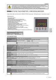
enda ets762 tacho line/speed meter - SURAN Industrieelektronik
enda ets762 tacho line/speed meter - SURAN Industrieelektronik
enda ets762 tacho line/speed meter - SURAN Industrieelektronik

You also want an ePaper? Increase the reach of your titles
YUMPU automatically turns print PDFs into web optimized ePapers that Google loves.
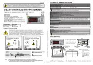
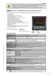
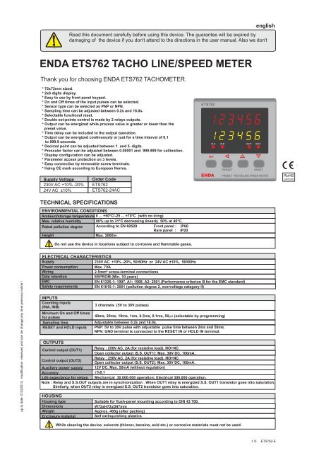
englishRead this document carefully before using this device. The guarantee will be expired bydamaging of the device if you don't attend to the directions in the user manual. Also we don'tENDA ETS762 TACHO LINE/SPEED METERThank you for choosing ENDA ETS762 TACHOMETER.* 72x72mm sized.* 2x6 digits display.* Easy to use by front panel keypad.* On and Off times of the input pulses can be selected.* Sensor type can be selected as PNP or NPN.* Sampling time can be adjusted between 0.2s and 16.0s.* Selectable functional reset.* Double set-points control is made by 2 relays outputs.* Output can be energized while process value is greater or lower than thepreset value.* Time delay can be included to the output operation.* Output can be energized continuously or just for a time interval of 0.1to 999.9 seconds.* Decimal point can be adjusted between 1. and 5. digits.* Prescaler factor can be adjusted between 0.00001 and 999.999 for calibration.* Display configuration can be adjusted.* Para<strong>meter</strong> access protection on 3 levels.* Easy connection by removable screw terminals.* Haing CE mark according to European Norms.Supply Voltage230V AC +10% -20%24V AC ±10%Order CodeETS762ETS762-24ACTECHNICAL SPECIFICATIONSENVIRONMENTAL CONDITIONSAmbient/storage temperature 0 ... +50°C/-25 ... +70°C (with no icing)Max. relative humidity 80% up to 31°C decreasing <strong>line</strong>arly 50%at 40 °C.Rated pollution degree According to EN 60529 Front panel : IP60Rare panel : IP20HeightMax. 2000mDo not use the device in locations subject to corrosive and flammable gases.ETS762IN A IN B OUT1 OUT2SETPRESETRESETENDAPRESET TACHO/LINE SPEED METERRoHSconformup to date: 01022014, modification reserved and can be change any time previous notice !ELECTRICAL CHARACTERISTICSSupply230V AC +10% -20%, 50/60Hz or 24V AC ±10%, 50/60HzPower consumption Max. 7VAWiring2.5mm² screw-terminal connectionsDate retentionEEPROM (Min. 10 years)EMCEN 61326-1: 1997, A1: 1998, A2: 2001 (Performance criterion B for the EMC standard)Safety requirements EN 61010-1: 2001 (pollution degree 2, overvoltage category II)INPUTSCounting inputs(INA, INB)Minimum On and Off timesfor pulsesSampling timeRESET and HOLD inputs3 channels (5V to 30V pulses)40ms, 20ms, 10ms, 1ms, 0.5ms, 0.1ms, 50 ms (selectable by programming)Adjustable between 0.2s and 16.0s.PNP: 5V to 30V pulse with adjustable pulse time between 2ms and 50ms.NPN: GND terminal is connected to the RESET IN or HOLD IN terminal.OUTPUTSRelay : 250V AC, 2A (for resistive load), NO+NCControl output (OUT1)Open collector output (S.S. OUT1): Max. 30V DC, 100mA.Relay : 250V AC, 2A (for resistive load), NO+NCControl output (OUT2)Open collector output (S.S. OUT2): Max. 30V DC, 100mA.Auxiliary power supply 12V DC, Max. 50mA (without regulation)Accuracy ±%0.1Life expectancy for relays Mechanical 30.000.000 operation; Electrical 300.000 operation.Note : Relay and S.S.OUT outputs are in synchronization . When OUT1 relay is energized S.S. OUT1 transistor goes into saturation.Similarly, when OUT2 relay is energized S.S. OUT2 transistor goes into saturation.HOUSINGHousing type Suitable for flush-panel mounting according to DIN 43 700.DimensionsW72xH72xD97mmWeightApprox. 405g (after packing)Enclosure material Self extinguishing plasticsWhile cleaning the device, solvents (thinner, benzine, acid etc.) or corrosive materials must not be used.1./5 ETS762-E
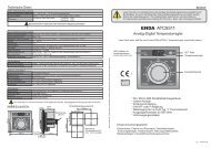
TERMSETS762ENDAIN A IN B OUT1 OUT2SETPRESETRESETPRESET TACHO/LINE SPEED METER(1) The value of the measurement selected byinputpara<strong>meter</strong> during run mode.typePara<strong>meter</strong> name during programming mode.(2) The value of the para<strong>meter</strong> selected by Set.dsp. para<strong>meter</strong> during run mode.configPara<strong>meter</strong> value during programming mode.(3) State indicators shows the state of the device.(4) Used for adjusting the preset values in the run mode.Increment or para<strong>meter</strong> selection key during programming mode.(5) Decrement or reset key in the run mode.Decrement or para<strong>meter</strong> selection key during programming mode(6) Used for selecting preset1, preset2 or user defined message in the run mode.Used for selectingoPtion.s or para<strong>meter</strong> to be changed in the programming mode.(7) Used for selecting run or programming modes or for adjusting para<strong>meter</strong>s.( 1 ) Digital display( 2 ) Digital displayCharacter height( 3 ) State indicators( 4 ),( 5 ),( 6 ),( 7 ) Keypad6 digits, seven segment red LED6 digits, seven segment yellow LEDDigital display (1) :Digital display (2) :4 red LEDsMicro switch9.1mm7.1mmDIMENSIONSETS76212Depth97mmPanel cut-out+0.768 mm75mm72mm78mmSETIN A IN B OUT1 OUT268 mm+0.7ENDAPRESETRESETPRESET TACHO/LINE SPEED METERConnectioncablesFor removing mounting clamps:- Push up the flush-mountingclamp in direction 1 asshown in the figure above.- Then, pull out the clamp indirection 2.84mmCONNECTION DIAGRAMFlush mountingclampPanelRubber packingNote 1) While panel mounting, additional distance required forconnection cables should be considered.2) Panel thickness should be maximum 10mm.3) If there is no 90mm free space at back side of the device,it would be difficult to remove it from the panel.ENDA ETS762 is intended for installation in control panels. Make sure that the device is used only for intendedpurpose. The shielding must be grounded on the instrument side. During an installation, all of the cables that areconnected to the device must be free of energy. The device must be protected against inadmissible humidity,vibrations, severe soiling and make sure that the operation temperature is not exceeded. All input and output<strong>line</strong>s that are not connected to the supply network must be laid out as shielded and twisted cables. These cablesshould not be close to the power cables or components. The installation and electrical connections must be3 HOLD IN4 RESET IN5 S.S. OUT2230V AC +10% -20%50/60Hz 7VAOUT1AC 250V 2ARESISTIVELOAD11121314153 HOLD IN4 RESET IN5 S.S. OUT224V AC ±10%50/60Hz 7VAOUT1AC 250V 2ARESISTIVELOAD1112131415NOTE :184-253V AC50/60Hz 7VA1112LineNeutralFuseF 100 mA250V ACFuse shouldbe connected.Switch230V AC SupplyCable size: 1,5mm²6 S.S. OUT17 IN BOUT2AC 250V 2ARESISTIVELOAD1617188 IN AENDAINDUSTRIAL9 GNDELECTRONICSETS76210 +12V 50mA SN: XXXXXXXXX6 S.S. OUT17 IN BOUT2AC 250V 2ARESISTIVELOAD1617188 IN AENDAINDUSTRIAL9 GNDELECTRONICSETS762-24AC10 +12V 50mA SN: XXXXXXXXXNote :1) Mains supply cords shall meet the requirements of IEC 60227or IEC 60245.2) In accordance with the safety regulations, the power supplyswitch shall bring the identification of the relevant instrumentHolding screw 0.4-0.5NmEquipment is protected throughoutby DOUBLE INSULATION.2./5 ETS762-E
7Pulse counting method1 2 3 4 5 6 7 8 91 2 3 4 5 6 7 8 9 10HIN A input LsecondCountper.pls.IN B inputRESET INHLHLTTdTT ³ 20msTd ³ 20mssecondsecondProcess value Previous value Counting value: 9Counting value: 9 ZEROPulstimeNote: should be selected according to the minimum On and Off times of the input pulses.8Pulse counting methodCountper.CYc.IN A inputIN B inputHLHL12345T678912345678 9 10 11 12 13TT ³ 20mssecondsecondHRESET IN LsecondProcess value Previous value Counting value: 9Counting value : 13 ZEROPulstimeNote: should be selected according to the minimum On and Off times of the input pulses.OUTPUT TYPESoutputconfig.out1.loout2.looutputconfig.= =out1.Hiout2.HiReset999,999Preset1Preset2Reset999,999Preset2Preset100Out1Out2out1del.tiout1del.tiOut1Out2out1del.tiout2del.tiout2del.tiout2del.tioutputconfig.=out1.Hi.out2.lo.outputconfig.=out1.lo.out2.Hi.Reset999,999Reset999,999Preset1Preset2Preset2Preset100Out1Out2out1del.tiOut1Out2out1del.tiout1del.tiout2del.tiout2del.tiout2del.tiout1Puls.ti.out2puls.ti. out1 out2puls.ti. puls.ti.Adjusting or to a value between 0.1 and 999.9 seconds,a pulse output is obtained.Adjusting or to 0.0, a continuous output is obtained.4/54./5 ETS762-EMEASUREMENT METHODS ACCORDING TO INPUT TYPESRevolution measurement method (rpm: revolution/minute)HIN A input LHHOLD IN input LsecondsecondT1T2T3Process valuePulstimePrevious value(1/T1x60) rpm(1/T2x60) rpm (1/T2x60) rpmprocess value do not changesNote: should be selected according to the minimum On and Off times of the input pulses.Ratio of the revolutions of IN A and IN BHIN A input LsecondTaTaTaHIN B input LsecondTb Tb Tb TbProcess valuePrevious value(1/Ta) / (1/Tb)PulstimeNote: should be selected according to the minimum On and Off times of the input pulses.Speed measurement methodHIN A input LsecondT1TdT2Td T3HIN B input LsecondProcess value Previous value (1/T1x60)m/dk.(1/T2x60)m/dk. (1/T3x60)m/dk.PulstimeNote: should be selected according to the minimum On and Off times of the input pulses.Period measurement methodHIN A input LsecondT1 T2TnTHLHHOLD IN input Lsampling timeprocess value do not changessecondProcess valuePrevious value(T1+T2+ ..... +Tn)/nPulstimeNote: should be selected according to the minimum On and Off times of the input pulses.Time difference measurement methodHIN A input LsecondT1TdT2Td T3HIN B input LsecondProcess value Previous value T1T2.T3PulstimeNote: should be selected according to the minimum On and Off times of the input pulses.Pulse duration measurement methodHIN A input LsecondT1Td T2T3 T4HHOLD IN input Lprocess value do not changesProcess value Previous valueT1T2T4PulstimeNote: should be selected according to the minimum On and Off times of the input pulses.123456inPuttyPE<strong>tacho</strong>inA.inbratioLine<strong>speed</strong>periodtimeinter.pUlstime.
TERMINAL CONNECTIONS230V AC +10% -20%50/60Hz 7VA3 HOLD IN OUT1AC 250V 2ARESISTIVE4 RESET IN LOAD5 S.S. OUT26 S.S. OUT1 OUT2AC 250V 2ARESISTIVE7 IN B LOAD11121314151617Terminal descriptions3 : Hold input4 : Reset input5 : Solid state out2 (Max 30V 100mA open collector NPN)6 : Solid state out1 (Max 30V 100mA open collector NPN)7 : IN A input (Max 30V 10kHz)8 : IN B i input (Max 30V 10kHz)9 : GND10 : +12V 50mA auxiliary power supply11,12 : SUPPLY inputs13,14,15 : 1. relay output (Max 2A 250V AC)16,17,18 : 2. relay output (Max 2A 250V AC)188 IN AENDAINDUSTRIAL9 GNDELECTRONICSETS76210 +12V 50mA SN: XXXXXXXXXTYPICAL SENSOR CONNECTIONSFuseF 100 mA250V ACSwitch230V AC +10% -20%50/60Hz 7VA3 HOLD IN OUT1AC 250V 2ARESISTIVE4 RESET IN LOAD11121314230V AC SupplyCable size: 1,5mm²PNP PROXIMITY SWITCHOUTGND+ 12V5 S.S. OUT26 S.S. OUT17 IN B8 IN A9 GND10 +12V 50mAOUT2AC 250V 2ARESISTIVELOADENDAINDUSTRIAL15161718ELECTRONICSETS762SN: XXXXXXXXX230V AC +10% -20%50/60Hz 7VA3 HOLD IN OUT1AC 250V 2ARESISTIVE4 RESET IN LOAD11121314FuseF 100 mA250V ACSwitch230V AC SupplyCable size: 1,5mm²PNP PROXIMITY SWITCHPNP PROXIMITY SWITCHOUTOUTGNDGND+ 12V+ 12V5 S.S. OUT26 S.S. OUT17 IN B8 IN A9 GND10 +12V 50mAOUT2AC 250V 2ARESISTIVELOADENDAINDUSTRIAL15161718ELECTRONICSETS762SN: XXXXXXXXXNOTE: NPN PROXIMITY SWITCH connection is the same as PNP PROXIMITY SWITCH connection.<strong>SURAN</strong> <strong>Industrieelektronik</strong> Tel.: +49 (0)7451 / 625 617 E-mail : info@suran-elektronik.deIm Mitteldorf 26 / D-72160 Horb a.N Fax: +49 (0)7451 / 625 0650 Internet : www.suran-elektronik.de5./5 ETS762-E