enda euc942 pid universal controller - SURAN Industrieelektronik
enda euc942 pid universal controller - SURAN Industrieelektronik
enda euc942 pid universal controller - SURAN Industrieelektronik
- No tags were found...

Create successful ePaper yourself
Turn your PDF publications into a flip-book with our unique Google optimized e-Paper software.
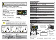
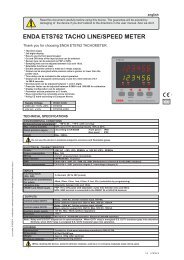
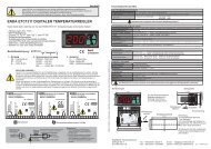
englishRead this document carefully before using this device. The guarantee will be expired bydamaging of the device if you don't attend to the directions in the user manual. Also we don'taccept any compensations for personal injury, material damage or capital disadvantages.ENDA EUC942 PID UNIVERSAL CONTROLLERThank you for choosing ENDA EUC942 <strong>universal</strong> <strong>controller</strong>.* 96 x 96mm sized.* Selectable sensor type.* Selectable 0-20mA or 4-20mA input.* Automatic calculation of PID parameters (SELF TUNE).Enter PID parameters of the system if they are known at the beginning.Otherwise, Self-Tune should be activated.* Soft-Start.* Communication via RS-485 ModBus protocol (Optional).* Selectable analog, SSR or relay control output.* Selectable 0-20mA or 4-20mA analog control output.* Relay output can be programmable as second alarm or control output.* AL1 relay output for first alarm out.* Selectable Heat/Cool control.* Input offset feature.* In the case of sensor failure periodical running or relay state can beselected.* Parameter access protection on 3 levels.* Programming by using keypad or Modbus.* CE marked according to European Norms.ENDACNT/AL2AN/SSRAL1SETCSETPVASETSVEUC 942UNIVERSAL CONTROLLERTECHNICAL SPECIFICATIONSInput type Temperature range Accuracy°C °FPt 100 Resistance Thermometer EN 60751Pt 100 Resistance Thermometer EN 60751-200...600 °C-99.9...300.0°C-328... +1112°F-99.9...+543.0°F0,2% ( of full scale)0,2% ( of full scale)J (Fe-CuNi) ThermocoupleK (NiCr-Ni) ThermocoupleEN 60584EN 605840... 600°C0...1200°C+32... +1112°F+32... +2192°F0,2% ( of full scale)0,2% ( of full scale)T (Cu-CuNi) Thermocouple EN 60584 0... 400°C+32... +752°F0,2% ( of full scale)S (Pt/0Rh-Pt) ThermocoupleR (Pt13Rh-Pt) Thermocouple0-20 mA4-20 mAEN 60584EN 60584EN 60584EN 605840...1600°C0...1600°C-999...4000-999...4000+32... +2912°F+32... +2912°F0,2% ( of full scale)0,2% ( of full scale)0,2% ( of full scale)0,2% ( of full scale)1 digit1 digit1 digit1 digit1 digit1 digit1 digit1 digit1 digitENVIRONMENTAL CONDITIONSAmbient/storage temperature 0 ... +50 °C/-25... +70°C (with no icing)Max. Relative humidity 80% up to 31°C decreasing linearly 50%at 40 °C.Rated pollution degree According to EN 60529 Front panel : IP65Rear panel : IP20HeightMax. 2000mDo not use the device in locations subject to corrosive and flammable gases.up to date: 01022014, modification reserved and can be change any time previous notice !ELECTRICAL CHARACTERISTICSSupply 230V AC +10% -20%, 50/60Hz or other power supply (please see page 5, order code)Power consumption Max. 7VAWiring2.5mm² screw-terminal connectionsLine resistanceFor thermocouple max.100 Ù, for 3 wired Pt 100 max. 20ÙData retentionEEPROM (minimum 10 years)EMCEN 61326-1: 1997, A1: 1998, A2: 2001 (Performance criterion B for standard EN 61000-4-3)Safety requirements EN 61010-1: 2001 (Pollution degree 2, overvoltage category II)OUTPUTSCONT./AL2AL1ANL/SSRLife expectancy for relayCONTROLControl typeControl algorithmA/D converterSampling timeProportional bandIntegral timeDerivative timeControl periodHysteresisOutput powerRelay : 250V AC, 2A ( for resistive load), NO/NC. Selectable as Control or Alarm2 output.Relay : 250V AC, 2A ( for resistive load), NO/NC selectable. (Alarm1 output).Selectable as 0-20mA, 4-20mA analog output (max. load 400 Ù) or logic control output 12V/20mAMechanical 30.000.000 operation; Electrical 300.000 operationSingle set-point and alarm controlOn-Off / P, PI, PD, PID (selectable)15 bits500msAdjustable between 0% and 100 %. If Pb=0 %, On-Off control is selected.Adjustable between 0.0 and 100.0 minutesAdjustable between 0.00 and 25.00 minutesAdjustable between 1 and 250 secondsAdjustable between 1 and 50°C/FThe ratio of power at a set point can be adjusted between 0% and 100%HOUSINGHousing type Suitable for flush-panel mounting according to DIN 43 700.DimensionsW96xH96xD50mmWeightApprox. 410g (after packing)Enclosure material Self extinguishing plastics.While cleaning the device, solvents (thinner, benzine, acid etc.) or corrosive materials must not be used.1./5 EUC942-E
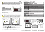
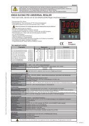
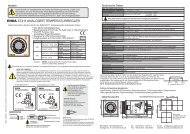
SETCSETASETSETIf key is pressed while holding key, the programming mode is enabled.ASETCSETCon.o.ASETALr.o.ASETConF.ASETPage 3/5Pb4tý4.0td1.00Ct20P.SEt.0C.HyS.2C.StA.HEAtPr.Er.0C.oT.S.Out1S.S.T.S.0A.o.L.L.Pb = Proportional band.Adjustable between 0% and 100%Setting Pb = 0% On-Off control isselected.Ti = Integral time.Adjustable between 0.0 and 100.0 minutes.If ti = 0.0, integral effect is not used.Setting Pb = 0 this parameter is not seen.td = Derivative time.Adjustable between 0.00 and 25.00 minutes.If td = 0.00, derivation effect is not used.Setting Pb = 0 this parameter is not seen.Ct = Control period.Adjustable between 1 and 250 seconds.Setting Pb = 0 andC.ot.S.= Out1 thisparameter is not seen.P.SEt. = The ratio of output power at the setpoint.Adjustable between 0% and 100%.If this parameter is set to 0, the output powerbecomes 0 at the set point. If it is adjusted to50% output power becomes 50% at the setpoint. Using this parameter the energyrequirements of the system is adjusted at theset point. So the set point can be achieved byminimum fluctuations and in the shortest time.Setting Pb = 0, this parameter is not seen.C.HYS. = Hysteresis of the control output.Adjustable between 1 and 50 °C/F.Adjustable between 0,1 and 50 °C/F ,if inp = Pt.0.Setting Pb = 0 this parameter is seen.C.StA. = Configuration of the control output.C.StA. = HEAt means heating control.C.StA. = cooL means cooling control.Pr.Er. = This parameter is used to adjust thecontrol output during a sensor failure.Adjustable between 0% and 100%.If this parameter is adjusted to a value closer tothe energy requirements of the system at the setpoint, process temperature is prevented to rise ordrop to dangerous levels.C.ot.S. = Type of control outputout1 = Out1 control output.0-20 = Analog control output.( 0mA %0 energy, 20mA %100 energy)Out1 = Alarm2 output.4-20 = Analog control output.( 4mA %0 energy, 20mA %100 energy)Out1 = Alarm2 output.s.s.r = SSR control output..Out1 = Alarm2 output.S.S.t.S. = Soft Star timer set point valueThis parameter indicates the time to reach setpoint value when the device is first enegised.Adjustable between 0 and 250 minutes.If 0 is selected, soft start feature will be enableand the device reaches set point value quickly.NOTE! Setting Pb = 0, softstart feature will bedisable.A.o.L.L. =Minimum analog output value(% output) ,adjustable between 0 and 100.A1.Hy.2A1.tp.ýndE.A1.St.Hý.A1.P.e.onA2.Hy.2A2.tp.ýndE.A2.St.Hý.A2.P.e.oFFA1. Hy. = Hysteresis of the Alarm1output.Adjustable between 1 and 50°C.A1.tP. = Function of Alarm1 output.Four kinds of functions can beselected.indE. = IndependentdE. = DeviationbAnd = BandbAn.i. = Band with inhibitionA1.St. = The state of Alarm1.If independent or deviation alarm isselected, this parameter can be Lo.and Hi. . For Lo. alarm output isenergized below the alarm set point.For Hi. alarm output is energizedabove the alarm set point. If bandalarm is selected, this parameter canbebIHI or boHI. bIHI meansalarm is activated inside theband. boHI means alarm is activatedoutside the band.A1.p.e. = State of Alarm1 output inthe case of sensor failure.If A1.p.e. = On , the alarm output isenergized during the sensor failure.If A1.p.e. = oFF, the alarm output is notenergized during the sensor failure.A2. Hy. = Hysteresis of the Alarm2output.Adjustable between 1 and 50°C.NOTE! IfC.ot.S. = .out1, thisparameter is not seen.A2.tP. = Function of Alarm2 output.Four kinds of functions can beselected.indE. = IndependentdE. = DeviationbAnd = BandbAn.i. = Band with inhibitionNOTE! IfC.ot.S. = .out1, thisparameter is not seen.A2.St. = The state of Alarm2.If independent or deviation alarm isselected, this parameter can be Lo.and Hi. . For Lo. alarm output isenergized below the alarm set point.For Hi. alarm output is energizedabove the alarm set point. If bandalarm is selected, this parameter canbebIHI or boHI. bIHI meansalarm is activated inside theband. boHI means alarm is activatedoutside the band.NOTE! IfC.ot.S. = .out1, thisparameter is not seen.A2.p.e. = State of Alarm2 output inthe case of sensor failure.If A2.p.e. = On, the alarm output isenergized during the sensor failure.If A2.p.e. = oFF, the alarm output is notenergized during the sensor failure.NOTE! IfC.ot.S. = .out1, thisparameter is not seen.ýnP.FE.cn.C.Hi.L.600C.Lo.L.0oFFS.0Unit°CA1.H.L.600A1.L.L.0A2.H.L.600A2.L.L.0fL.Co.5inP. = Type of input and scale.Pt = Pt 100 -200 to +600°CPt.0 = Pt 100 -99.0 to +300.0°CFE.cn. = J (Iron vs. Copper-Nickel) 0 to +600°Cnc.nA. = K (Nickel-Cr.vs. Nickel-Alum.) 0 to +1200°Cc.cn. = T (Copper vs. Copper-Nickel) 0 to +400°CP10.r. = S (Platinum-10%Rhodium vs. Pt.) 0 to +1600°CP13.r. = R (Platinum-13%Rhodium vs. Pt.) 0 to +1600°C0-20 = 0-20 mA -999 to 30004-20 = 4-20 mA -999 to 3000Note : If the selected input type is changed, the value ofC.Hi.L, C.Lo.L , A.Hi.L. , A.Lo.L. parameters changesautomatically.C.Hi.L. = Set point upper limit.IfInP. orUnIt.parameters are changed, the maximumvalue of theC.Hi.L.parameter changes to the maximumscale value of the selected input. The minimum value isthe value of C.Lo.L. parameter.C.LoL. = Set point lower limit.If InP. or UnIt. parameters are changed, the minimumvalue of theC.Lo.L.parameter changes to the minimumscale value of the selected input. The maximum value isthe value ofC.Hi.L.parameter.oFFS. = Offset value.Offset value is added to the measurement value.Adjusted between -99 and +99°C.The normal value is 0.UnIt = The temperature unit.Selectable as °C or °F.Note : If the temperature unit is changed, the value ofthe UPL. , Lol. , A.UP.L. , A.Lo.L. Parameters changesautomatically.NOTE! IfInpparameter is selected TC or Pt100, thisparameter is seen.A1.H.L = Alarm1 value upper limit.IfInP. orUnIt.parameters are changed, the maximumvalue of theA1.H.L.parameter changes to the maximumscale value of the selected input type. Minimum ofA1.H.L. parameter is the value ofA1.L.L.parameter.A1.L.L. = Alarm1 value lower limit.IfInP. orUnIt.parameters are changed, the minimumvalue of theA1.L.L.parameter changes to the minimumscale value of the selected input type. The maximumvalue is the value ofA1.H.L.parameter.A2.H.L = Alarm2 value upper limit.IfInP. orUnIt.parameters are changed, the maximumvalue of theA2.H.L.parameter changes to the maximumscale value of the selected input type. Minimum ofA2.H.L. parameter is the value ofA2.L.L.parameter.NOTE! IfC.ot.S. = .out1, this parameter is not seen.A2.L.L. = Alarm2 value lower limit.IfInP. orUnIt.parameters are changed, the minimumvalue of theA2.L.L.parameter changes to the minimumscale value of the selected input type. The maximumvalue is the value ofA2.H.L.parameter.NOTE! IfC.ot.S. = .out1, this parameter is not seen.fL.Co. = Coefficient of digital filter.Filter for display value.Adjustable between 1 and 32. If this parameter is 1,digital filter runs most quick. If the parameter is 31, thefilter run most slow. The value of parameter should beincreased in interference.A.o.H.L.A.o.H.L. =Maximum analog output value(% output) ,adjustable between 0 and 100.ConF. Page 3/5Modification of ParameterC.HyS.6SETCSETC.HyS.6SETCSETC.HyS.5SETCSETC.HyS.6SETCSETSETWhen holding key, the value of parameter flashes and using keys the requested value can be adjusted.CSETIfkey is pressed and held 0.6 seconds, the value of the selected parameter changes ra<strong>pid</strong>ly. If waited enough,the value increases 100 at each step. After 1 second following the release of the key, initial condition is returned.The same procedure is valid for the decrement key.2./5 EUC942-E
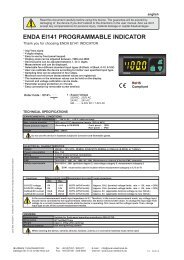
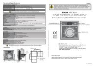
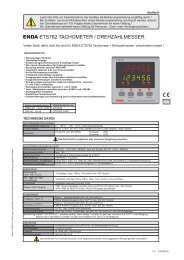
Entering from the programming mode to the run mode:If no key is pressed within 20 seconds during programming mode, the data is stored automatically and the run mode is entered.Alternatively, the same function occurs first pressing key and then pressing keys together.ASETCSET ASETSETSETCSETASETPage 2/5ASETS.tun.ASETSECU.ASETConF. Page 2/5Before starting sef-tuneprocedure, be sureA.tunparameter isYESin theSECUmenu.S.cod.0S.cod. = Security menu accesscode.It should be 666.U.sC.l.-999U.sC.H.4000d.pnt.0U.sC.l. = Lower scale value for mA inputs.Adjustable between -999 and the ( U.sC.H. - 100)NOTE! IfInp is selected one of the mA input types, thisparameter is seen.U.sC.H. = Upper scale value for mA inputs.Adjustable between ( U.sC.l. + 100) and 4000.NOTE! IfInp is selected one of the mA input types, thisparameter is seen.d.pnt. = Decimal point for mA inputs.Adjustable between 0 and 2.NOTE! IfInp is selected one of the mA input types, thisparameter is seen.A.Con.P.yESA.ALr.P.yESA.CNF.P.yESA.Con. = Parameters ofCoN.omenuaccess level code.nonE = InvisibleP.yES = Modification can be done.P. no = Only visible.A.ALr.. = Parameters ofALr.omenu access level code.nonE = InvisibleP.yES = Modification can be done.P. no = Only visible.A.CNf. = Parameters ofConF.menuaccess level code.nonE = InvisibleP.yES = Modification can be done.P. no = Only visible.d.adr.1d.adr. = Device address.Adjusable between 1 and 247. Difference addressesshould be selected for every device.A.tun.yESA.tun. = Parameters ofS.tun.menuaccess level code.no = InvisibleyES = Self tune can be done.baudoffBaud= Modbus baud rate.Selectable 1200, 2400, 4800 and 9600.If baud=off, Modbus communication will be disable.S.Str.runSETCSETpress and holdS.Str.runSETCSETProcess value isequal or lower than60 %of the set point ?No70TE.Hý.When process value decreasesappropriate temperatureto self tuneYes25REdY.Pressany key25Pýd.t.AfterPID iscalculated25P.SE.t.Press any keyto deactivatethe self-tune procedure.SETWhile holding key, run message flashes. Then when key is pressed, self tune mode is entered if there is no probe failure. If process value isCSETappropriate to begin self tune, rEdY. message flashes. Then press any key to seePid.t.message and self tune procedure begins.Process value must be equal or lower than 60%of the setpoint to begin self tune procedure. If not, tE.Hi. message flashes and device waits to decreaseappropriate temperature to begin self tune. ThenrEdY.message flashes and press any key to begin sellf tune procedure.Before self tune procedure, A.tun. parameter must be selectedyES from theSECU menu.If self tune is achievedA.tun. parameter becomesnoautomaticallyandS.tunmenu is canceled. Before self tune procedure, temperature setpoint value should be adjusted. When self tune procedure begins with no failure,Pid.t. message flashes and remains during the calculation of PID parameters. When PID parameters are calculated, P.SE.t. message flashes. Then the deviceheats until setpoint value according to PID parameters and calculates the energyrequirement for stable temperature and writesP.SE.t.parameter as %and runmode enters.If any key is pressed while Pid.t. message flashes, self tune prosedure is deactivated before calculation of PID parameters. If any key is pressed while P.SE.t.3./5 EUC942-E
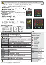
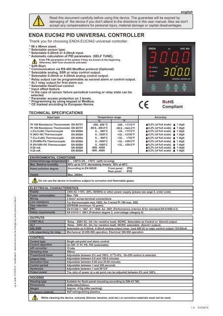
TERMSENDAPVEUC 942( 1 ) Process value during normal operationMnemonic parameter code during programming( 2 ) Set point during normal operation.Data value during programming( 7 )CNT/AL2AN/SSRAL1SETCSETASETSVUNIVERSAL CONTROLLER( 3 ) Increment key during normal operation and programmingParameter selection key during programming( 4 ) Decrement key during normal operationIf only this key is pressed in normal operation, software version number is seen.Parameter selection key during programming( 5 ) Alarm set key during normal operationMenu selection key during programming( 6 ) Control set key during normal operationParameter selection key during programming( 1 ) PV display( 2 ) SV displayCharacter heights( 3 ),( 4 ),( 5 ),( 6 ) Keypad( 7 ) State indicator4 digits 7 segment red LED4 digits 7 segment yellow LEDPV display :20 mmSV display :14 mmMicro switchALARM1 AND ALARM2 OUTPUT TYPESIndependent Alarm Deviation AlarmA1.tP. = indE A1.tP. = DE.3 red LEDs for Control, Alarm1 and SSR outputsBand AlarmA1.tP. = bAndSVON SV ON SVONOFF OFF A.StA. = HiOFF A1.St. = boHiON ON ONOFF OFF A.StA. = Lo OFF A1.St. = biHia1.Hy. A1.Hy.. A1.Hy. A1.Hy.ASVSV-ASV SV+ASV( ASV min = beginning of scale -300 SV+ASV +300 300300ASV max = end of scale)(ASV min. =-300, ASV max. = +300)SV = Set point of CONT output ASV = Set point of AL1 output(If inP = Pt..0,ASV min. = -30.0,ASV max. = +30.0)(ASV min. = 0, ASV max. = +300)SV = Set point of CONT output ASV = Set point of alarm output(If inP = Pt..0,ASV min. = 0.0, ASV max. = +30.0)Band Alarm With InhibitionA1.tP. = BAn.i.SV+ASVSVSV-ASVSV+ASVSVSV-ASVONOFFONOFFBeginningof procedureBand alarm is possibleBeginningof procedureBand alarm is possibleSV =Set point of CONT output ASV = Set point of AL1 output (ASV min. = 0, ASV max. = 300 )MODIFICATION OF CONTROL AND ALARM SET POINTS130150PVSVSETCSETC.SEt150PVSVSETCSETC.SEt149PVSVSETCSETC.SEt150PVSVWhen CSET is released, itreturns to normal operation.SETCSETSETFirst, press and hold key until the massageC.Setappears on the display. Then, the value is adjusted by using keys.CSETA1.sE.250PVA1.sE.249SVSVASET ASET ASETPVA1.sE.250PVSVASETWhen ASET is released, itreturns to normal operation.First, press and hold key, alarm setpoint value appears on the display. Then, the value is adjusted by using keys. .ASETIfC.ot.S different fromout1.Alarm1 and Alarm2 setpoint values can be adjusted in sequence when per press key.ASETNOTE: The maximum of C.SEt is the value of C.Hi.L. parameter and the minimum of it is the value ofC.Lo.L.parameter.If independent alarm is selected, A1.SE. andA2.SE.values can be adjusted between the limits of the full scale.If deviation alarm is selected, A1.SE. andA2.SE.values can be adjusted between -300 and + 300.If band alarm is selected, A1.SE. andA2.SE.values can be adjusted between0 and + 300.Error Messages- - - -- - - - PFA150 150 150Temperature value ishigher than the scalePV PV PV PVPSCSV SV SV SVTemperature value islower than the scaleTemperature sensoris broken or over temperature150Pt 100 or a sensorline is short circuited4./5 EUC942-E
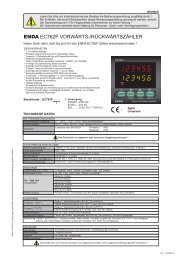
-+-+DIMENSIONS98mmENDAPVEUC 94296mmCNT/AL2AN/SSRAL1SVUNIVERSAL CONTROLLER1For removing the device fromthe panel:-While pressing both side ofthe device in direction 1, push itin direction 2.Depth50mmSETCSETASETFlush mountingclampPanel cut-out104mm290.5mm99mm90.5mmGasketPanel57mmNote : 1) Panel thickness should be maximum 10mm.2) If there is no 60mm free space at back side of the device,it would be difficult to remove it from the panel.CONNECTION DIAGRAMENDA EUC942 is intended for installation in control panels. Make sure that the device is used only for intended purpose. Theshielding must be grounded on the instrument side. During an installation, all of the cables that are connected to the devicemust be free of energy. The device must be protected against inadmissible humidity, vibrations, severe soiling and make surethat the operation temperature is not exceeded. All input and output lines that are not connected to the supply network mustbe laid out as shielded and twisted cables. These cables should not be close to the power cables or components. Theinstallation and electrical connections must be carried on by a qualified staff and must be according to the relevant locallyapplicable regulations.Screw-terminal connectionsENDA INDUSTRIAL ELECTRONICSEUC942-230VAC-RSPID UNIVERSAL CONTROLLER230V AC +10% -20%50/60Hz 7VAOUT1 / AL2 OUTAC 250V 2ARESISTIVE LOADAL1 AC 250V 2ARESISTIVE LOADSN: XXXXXXXXX(mA inp).-1 2 3 4 5 6 7 8 9 10 11 12 13 14 15Pt 100TC+ANL/SSROUT-+RS-485 COM.-BRS- 485+AENDA INDUSTRIAL ELECTRONICSEUC942-24VACPID UNIVERSAL CONTROLLER24V AC ±10%50/60Hz 7VAOUT1 / AL2 OUTAC 250V 2ARESISTIVE LOADAL1 AC 250V 2ARESISTIVE LOADSN: XXXXXXXXX(mA inp).1 2 3 4 5 6 7 8 9 10 11 12-Pt 100TC+ANL/SSROUT-+Logic output of the instrument is notelectrically insulated from theinternal circuits. Therefore, whenusing a grounding thermocouple, donot connect the logic outputterminals to the ground.Note 1) Mains supply cords shall meetthe requirements of IEC 60227 orIEC 60245.2) In accordance with the safetyregulations, the power supplyswitch shall bring the identificationof the relevant instrument and itshould be easily accessible by theHolding screw0.4-0.5NmEquipment is protected throughoutby DOUBLE INSULATION.NOTE :SUPPLY :184-253V AC50/60Hz 7VASENSOR INPUT :12LineNeutralFuseF 100 mA250V ACFuse shouldbe connected.For J-K-T-S-R type thermocouple :Use suitable compensation cables. Don't usejointed cables. Pay attention to the polaritiesof the thermocouple cables as shown in thefigure right are connected to the .For resistance thermometer :When 2 wired Pt 100 is used, terminals 9and 10 must be short circuited.switch230V ,110V or 24V ACSupplyCable size: 1,5mm²TCPt 100+-+0-20mA or4-20mA input -10989898Order Code : EUC942--1 21- Supply Voltage230VAC...230V AC110VAC...110V AC24VAC.....24V ACSM...........9-30V DC / 7-24V AC2- Modbus OptionRS........RS-485 Modbus communicationNone....Don’t support RS-485 Modbus communication<strong>SURAN</strong> <strong>Industrieelektronik</strong> Tel.: +49 (0)7451 / 625 617 E-mail : info@suran-elektronik.deDettinger Str. 9 / D-72160 Horb a.N Fax: +49 (0)7451 / 625 0650 Internet : www.suran-elektronik.de5./5 EUC942-E