Friction-Based Design of Kinematic Couplings
Friction-Based Design of Kinematic Couplings
Friction-Based Design of Kinematic Couplings
- No tags were found...

You also want an ePaper? Increase the reach of your titles
YUMPU automatically turns print PDFs into web optimized ePapers that Google loves.
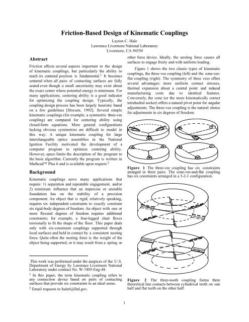
<strong>Friction</strong>-<strong>Based</strong> <strong>Design</strong> <strong>of</strong> <strong>Kinematic</strong> <strong>Couplings</strong>Layton C. HaleLawrence Livermore National LaboratoryLivermore, CA 94550Abstract<strong>Friction</strong> affects several aspects important to the design<strong>of</strong> kinematic couplings, but particularly the ability toreach its centered position is fundamental. 1 It becomescentered when all pairs <strong>of</strong> contacting surfaces are fullyseated even though a small uncertainty may exist aboutthe exact center where potential energy is minimum. Formany applications, centering ability is a good indicatorfor optimizing the coupling design. Typically, thecoupling design process has been largely heuristic basedon a few guidelines [Slocum, 1992]. Several simplekinematic couplings (for example, a symmetric three-veecoupling) are compared for centering ability usingclosed-form equations. More general configurationslacking obvious symmetries are difficult to model inthis way. A unique kinematic coupling for largeinterchangeable optics assemblies in the NationalIgnition Facility motivated the development <strong>of</strong> acomputer program to optimize centering ability.However, space limits the description <strong>of</strong> the program tothe basic algorithm. Currently the program is written inMathcad Plus 6 and is available upon request. 2Background<strong>Kinematic</strong> couplings serve many applications thatrequire: 1) separation and repeatable engagement, and/or2) minimum influence that an imprecise or unstablefoundation has on the stability <strong>of</strong> a precisioncomponent. An object that is rigid, relatively speaking,requires six independent constraints to exactly constrainsix rigid-body degrees <strong>of</strong> freedom. An object with one ormore flexural degrees <strong>of</strong> freedom requires additionalconstraints; for example, a four-legged chair flexestorsionally to fit the shape <strong>of</strong> the floor. This paper dealsonly with six-constraint couplings supported throughlocal surfaces and held in contact by a consistent nestingforce. Quite <strong>of</strong>ten the nesting force is the weight <strong>of</strong> theobject being supported, or it may result from a spring orother force device. Ideally, the nesting force causes allsurfaces to engage freely and with uniform loading.Figure 1 shows the two classic types <strong>of</strong> kinematiccouplings, the three-vee coupling (left) and the cone-veeflatcoupling (right). The symmetry <strong>of</strong> three vees <strong>of</strong>fersseveral advantages: more uniform contact stresses,thermal expansion about a central point and reducedmanufacturing costs due to identical features.Conversely, the cone (or the more kinematically correcttetrahedral socket) <strong>of</strong>fers a natural pivot point for angularadjustments. The three-vee coupling is the natural choicefor adjustments in six degrees <strong>of</strong> freedom.Figure 1 The three-vee coupling has six constraintsarranged in three pairs. The cone-vee-and-flat couplinghas six constraints arranged in a 3-2-1 configuration.This work was performed under the auspices <strong>of</strong> the U.S.Department <strong>of</strong> Energy by Lawrence Livermore NationalLaboratory under contract No. W-7405-Eng-48.1 In this paper, the term kinematic coupling refers toany connection device based on pairs <strong>of</strong> contactingsurfaces that provide six constraints in an ideal sense.2 Email requests to hale6@llnl.gov.Figure 2 The three-tooth coupling forms threetheoretical line contacts between cylindrical teeth on onehalf and flat teeth on the other half.1
The local contact areas typical <strong>of</strong> these kinematiccouplings are quite small and require a Hertzian analysisto ensure a robust design. Greater durability is achievedby curvature matching such as a ball against a concavesurface and/or by using ceramic materials such as siliconnitride balls against tungsten carbide gothic arches.<strong>Design</strong>s based on line contact rather than point contact<strong>of</strong>fer a significant increase in load capability. Forexample, a kinematic equivalent to three vees is a set <strong>of</strong>three balls in three conical sockets with either the ballsor the sockets supported on radial-motion flexures.Alternatively, the three-tooth coupling shown in Figure2 is based on three theoretical lines <strong>of</strong> contact formedbetween cylindrical and flat teeth. Each line constrainstwo degrees <strong>of</strong> freedom giving a total <strong>of</strong> six constraints.Manufactured with three identical cuts directly into eachcoupling half, the teeth must be straight along the lines<strong>of</strong> contact but other tolerances can be relatively loose.<strong>Friction</strong> Effects<strong>Friction</strong> affects at least four important characteristics <strong>of</strong>a kinematic coupling as indicated by order-<strong>of</strong>-magnitudeestimates that all include the coefficient <strong>of</strong> friction µ.1) Repeatabilityfk2) <strong>Kinematic</strong> support ft≤µ fn3) StiffnessP≈ µ ⎛ 2 13 23⎞ ⎛ ⎞⎝ 3R⎠⎝ E⎠132−2ν⎛ fkt= kt ⎞n ⎜1− ⎟2 − ν ⎝ µ fn⎠≈ 083 . knf4) Centering ability c ≈ 05 . −13. µfnTangential friction forces at the contacting surfacesmay vary in direction and magnitude depending how thecoupling comes into engagement. This affects therepeatability <strong>of</strong> the coupling and the kinematic support<strong>of</strong> the precision component. The estimate forrepeatability is the unreleased frictional force multipliedby the coupling’s compliance. The estimate is derived asif the coupling’s compliance in all directions is equal toa single Hertzian contact carrying a load P and having arelative radius R and elastic modulus E. The frictionalforce acts to hold the coupling <strong>of</strong>f center in proportionto the compliance. This estimate will underestimate therepeatability if the structure <strong>of</strong> the coupling is relativelycompliant compared to the contacting surfaces.<strong>Kinematic</strong> support is important for stability <strong>of</strong>shape <strong>of</strong> the precision component. The estimate forkinematic support simply gives a bound on themagnitude <strong>of</strong> friction force acting at any contact surface.A sensitivity analysis <strong>of</strong> the precision component willdetermine a tolerable level <strong>of</strong> friction that the couplingcan have. This may drive the design to include flexureelements and/or procedures to release stored energy. Ifrepeatable engagement is not so important, thenconstraints using rolling-element bearings <strong>of</strong>fer very lowfriction. For example, a pair <strong>of</strong> cam followers thatcontact with crossed axes is equivalent to a ball on a flatbut with twenty or so times less friction.In some cases frictional overconstraint is valuablefor increasing the overall system stiffness. Provided thetangential force is well below what would initiatesliding, the tangential stiffness <strong>of</strong> a Hertz contact iscomparable to the normal stiffness [Johnson, 1985].This was important for the National Ignition Facilitywhere frictional overconstraint stiffened the firsttorsional mode <strong>of</strong> optics assemblies sufficiently to meetdynamic stability requirements.Centering ability can be expressed as the ratio <strong>of</strong>centering force to nesting force and the estimate shownis typical. A larger ratio means the coupling is better atcentering in the presents <strong>of</strong> friction. Later, it isconvenient to express centering ability as the coefficient<strong>of</strong> friction where the ratio goes to zero. For the estimate,the limiting coefficient <strong>of</strong> friction is 0.5/1.3 = 0.38. Thecoupling will center if the real coefficient <strong>of</strong> friction isless than the limiting value.Centering AbilityThe contacting surfaces <strong>of</strong> a kinematic coupling comeinto engagement sequentially unless it is placedprecisely at the exact center. The path to center isconstrained by the surfaces already in contact. Forexample, five surfaces in contact constrain the couplingto slide along a well-defined path. Four surfaces incontact allow motion over a two-dimensional surface <strong>of</strong>paths and so forth. Although there are infinitely manypaths to center, only the limiting case is <strong>of</strong> practicalinterest for determining centering ability. Further, it isreasonable to expect the limiting case to be one <strong>of</strong> sixpossible paths that have five surfaces in contact. 3 Thispoint is demonstrated using the three-vee coupling.For any given path to center, the centering forcethat results from the nesting force may be derived usingStatics and the Coulomb law <strong>of</strong> friction. Figure 3 shows3 The exception to this statement is the ball-coneconstraint <strong>of</strong> the cone-vee-flat coupling since the coneprovides only one constraint until the ball is fullyseated. A tetrahedral socket remedies this situation.2
examples <strong>of</strong> centering force (per unit nesting force)plotted versus the coefficient <strong>of</strong> friction. These curveswere generated from closed-form equations yet to bediscussed. Although the curves look simple, theequations are rather tedious to develop even when thecoupling has simple geometry and the load issymmetrical. Compound this with the possible number<strong>of</strong> paths to center and it becomes obvious that asystematic, computer-based approach is essential fordesigning more general configurations <strong>of</strong> couplings.with five surfaces in contact may have greater centeringforce than another path with four surfaces in contact.However as the coupling continues toward center, thecentering force cannot increase as it picks up the fifthcontact surface. Thus, we need only look at paths withfive surfaces in contact to determine the limiting case.0.6α = 45 deg0.40.200 0.1 0.2 0.3 0.4Eq. 1: 3V rotate about I.C.Eq. 2: 3V translate along VEq. 3: CVF translate along VEq. 4: 3T translate on 4 facesFigure 3 Centering force versus coefficient <strong>of</strong> friction.Figure 4 shows a symmetric three-vee couplingrotating about its instant center to reach the centerposition. This path has five surfaces in contact and isthe limiting case along with five other symmetricallyidentical paths. Equation 1 provides the centering forcefor this path assuming the nesting force is uniformlycarried by three balls. Note, the sides <strong>of</strong> the vees are anangle α with respect to the plane <strong>of</strong> the three balls. Inaddition, there are two sets <strong>of</strong> symmetrically identicalpaths having four surfaces in contact. Equation 2provides the centering force for the more limiting pathwhere the coupling translates radially along one vee. Theother path is rotation about one ball.Figure 4 The limiting case for centering occurs whenthe three-vee coupling slides on five surfaces producingrotation about its instant center.It is also useful to compare the centering forces forthe other types <strong>of</strong> kinematic couplings. Figure 5 showsthe cone-vee-flat coupling translating along its vee. Thispath is underdetermined for a conical socket but isrepresentative <strong>of</strong> the limiting case. It was chosen tosimplify the expression for centering force given inEquation 3. Referring back to Figure 3, it may come asa surprise that the cone-vee-flat coupling has the leastcentering ability <strong>of</strong> the three types. However, significantimprovement is possible by carrying more load with thecone and by increasing the cone angle.fcsin α − µ cosα=fn( cos + sin ) − µα µ α cosα− µ3 3 3(3)fcfnsin α − µ cosα3 µ=2 cosα + µ sin α 3cosα( ) −(1)2fc3 4+ 3tanα sin α −4µµ=−fn3⎡24+ 3tan α cosα + 3µ tan α⎤ 3cosα (2)⎣⎢⎦⎥This example shows that the path with five surfacesin contact has less centering force than either path withfour surfaces in contact. This may not be universallytrue for a general kinematic coupling. That is, a pathFigure 5 The limiting case for centering occurs whenthe cone-vee-flat coupling slides on the vee and flat withthe cone seeking center.3