Concepts for a Kinematically Coupled Robot Baseplate System
Concepts for a Kinematically Coupled Robot Baseplate System
Concepts for a Kinematically Coupled Robot Baseplate System

Create successful ePaper yourself
Turn your PDF publications into a flip-book with our unique Google optimized e-Paper software.
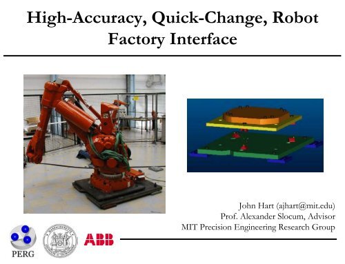
High-Accuracy, Quick-Change, <strong>Robot</strong><br />
Factory Interface<br />
John Hart (ajhart@mit.edu)<br />
Prof. Alexander Slocum, Advisor<br />
MIT Precision Engineering Research Group
Project Goals<br />
Design, test, and demonstrate production feasibility of a modular<br />
robot baseplate with kinematic couplings as locators:<br />
• A repeatable, rapidly exchangeable interface between the foot<br />
(three balls/contactors) and floor plate (three grooves/targets)<br />
• Calibrate robots at ABB to a master baseplate<br />
• Install production baseplates at the customer site and calibrated<br />
the kinematic couplings directly to in-cell tooling<br />
• Install robot according to refined mounting process with<br />
gradual, patterned preload to mounting bolts<br />
• TCP-to-tooling relationship is a deterministic frame<br />
trans<strong>for</strong>mation<br />
• Base calibration data handling is merged with ABB software,<br />
enabling 0.1 mm TCP error contribution from repeatability<br />
and exchangeability error of kinematic couplings
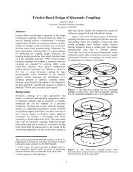
Prototype Coupling Designs<br />
Design 3-point kinematic coupling mounts <strong>for</strong> the 6400R foot:<br />
Canoe Ball<br />
• Six “point” contacts<br />
• 0.5m radius ball surface<br />
• 20 mm diameter elastic<br />
Hertzian contact<br />
Three-Pin<br />
• Three line + three surface contacts<br />
• In-plane preload overcomes<br />
friction to deterministically seat<br />
pins<br />
• Vertical bolt preload engages<br />
horizontal contact surfaces
Prototype Coupling Designs<br />
Groove/Cylinder<br />
• Twelve line contacts<br />
• Aluminum cylinders<br />
• Apply bolt preload (elastic<br />
deflection of cylinders) <strong>for</strong><br />
dynamic stability
Prototype Base Mounting<br />
Tests at ABB <strong>Robot</strong>ics Vasteras, July/August 2001:<br />
• Static (bolted) and dynamic (5-point path)<br />
repeatability of canoe ball and three-pin<br />
interfaces<br />
• Static (manipulator rest only) repeatability<br />
of groove/cylinder interface<br />
• Test both basic (air wrench) and refined<br />
(torque wrench, greased bolts) mounting<br />
processes<br />
• Measure tool point motion using Leica<br />
LTD500 Laser Tracker<br />
• Repeatability of robot path +<br />
measurement system approximately 20<br />
microns
Repeatability Per<strong>for</strong>mance<br />
0.45<br />
0.40<br />
• Canoe balls vs. BMW<br />
base = 83% reduction<br />
Repeatability [mm]<br />
0.35<br />
0.30<br />
0.25<br />
0.20<br />
0.15<br />
0.10<br />
0.05<br />
0.00<br />
BMW<br />
base (diff.<br />
robots)<br />
Three-pin:<br />
basic<br />
mounting<br />
Three-pin:<br />
refined<br />
mounting<br />
Canoe<br />
balls:<br />
basic<br />
mounting<br />
Design<br />
Canoe<br />
balls:<br />
refined<br />
mounting<br />
Aluminum<br />
cylinders:<br />
(static)<br />
basic<br />
mounting<br />
Aluminum<br />
cylinders:<br />
(static)<br />
refined<br />
mounting<br />
• Three-pin vs. BMW base<br />
= 85% reduction<br />
• Cylinders vs. BMW base<br />
= 92% reduction<br />
• Refined mounting vs.<br />
basic mounting = 50-<br />
70% reduction<br />
• 8-bolt blue pallet<br />
repeatability (not shown)<br />
= 1.63 mm
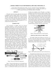
Interchangeability Error Model<br />
Consider stackup of errors in coupling manufacturing, mounting plate<br />
manufacturing, and coupling-to-plate assembly:<br />
For example in z-direction of a ball mount, tolerances:<br />
• Sphere radius = δ Rsph<br />
• Contact point to bottom plane = δ hR<br />
• Measurement feature height = δ hmeas<br />
• Protrusion height = δ hprot<br />
⎛⎛<br />
⎛δ<br />
Rsph ⎞ ⎞⎞<br />
⎜⎜2⎜<br />
⎟ + δhR + δhprot + δhmeas<br />
+ ⎟⎟<br />
1 ⎜⎜<br />
⎝ 2 ⎠<br />
⎟⎟<br />
ε<br />
z<br />
= ⎜ 2<br />
2<br />
⎜<br />
⎟ ⎟<br />
⎜⎜<br />
⎛δ<br />
Rsph ⎞ 2 2 2<br />
2 δhR δhprot δ<br />
⎟⎟<br />
⎜⎜<br />
⎜ ⎟ + + + hmeas<br />
2<br />
⎟⎟<br />
⎝⎝<br />
⎝ ⎠<br />
⎠⎠<br />
h meas<br />
h R<br />
R ball<br />
Each dimension is perturbed by generating a random variate, e.g. <strong>for</strong> mounting hole<br />
placement:<br />
xh = x<br />
,<br />
RandN()cos( )<br />
b h<br />
+ δ<br />
1 b R h<br />
δ<br />
1nom<br />
b pos<br />
θrand<br />
1<br />
θrand<br />
= 2π<br />
Rand()<br />
y = y + δ δ RandN()sin( θ )<br />
h h R,<br />
h pos rand<br />
b1 b1nom<br />
b1<br />
z<br />
y<br />
h prot
Interchangeability Solution Method<br />
Linear system of 24 constraint equations between the balls and grooves –<br />
accounts <strong>for</strong> both positional and angular misalignment:<br />
1. Contact sphere centers must be at minimum (normal) distance between the groove<br />
flats, e.g.:<br />
( − )<br />
q b ⋅N<br />
1 1 1<br />
N<br />
1<br />
2. By geometry, the combined error motion of contact spheres is known with respect<br />
to the error motion of their mounting plate. For small angles, e.g.:<br />
3. Solve linear system and place six error parameters in HTM:<br />
1 −θ θ δ<br />
T<br />
= R<br />
xs,1 = δ x + us,1 + vs,1 ⎡ w<br />
c ⎣− θz ⎤<br />
c⎦+<br />
s,1<br />
⎡<br />
⎣θy<br />
⎤<br />
c⎦<br />
ys,1 = δ<br />
y<br />
+ us,1 ⎡ vs,1 w<br />
c ⎣θz ⎤<br />
c⎦+ +<br />
s,1<br />
⎡<br />
⎣−θx<br />
⎤<br />
c⎦<br />
z = δ + u ⎡ θ ⎤ v ⎡θ<br />
⎤ w<br />
c ⎣− + +<br />
c⎦ ⎣ c⎦<br />
s,1 z s,1 y s,1 x s,1<br />
interface<br />
1<br />
q 1 , b 1 = initial, final center positions;<br />
N 1 = groove normal; R 1 = sphere radius.<br />
⎡<br />
zc yc x ⎤<br />
c<br />
⎢<br />
⎥<br />
θz 1 −θ c x<br />
δ<br />
c yc<br />
=<br />
⎢<br />
⎥<br />
⎢ −θ y θ 1<br />
c x δ ⎥<br />
c z<br />
⎢<br />
c<br />
⎥<br />
⎢⎣<br />
0 0 0 1 ⎥⎦<br />
(q S,1 , q S,1 , q S,1 ) = initial center positions;<br />
(x S,1 , y S,1 , z S,1 ) = final center positions.
Interchangeability Results<br />
Simulate interchangeablity error from manufacturing variation:<br />
• Calibrate interfaces by measuring<br />
contacts and calculating interface<br />
error trans<strong>for</strong>mation<br />
• Model direct measurement of pins +<br />
contacts, and offset measurement of<br />
canoe balls<br />
• Exchangeability is error between<br />
calculated and true interface<br />
trans<strong>for</strong>mation, given chosen level of<br />
calibration and manufacturing<br />
tolerances (low, med, high)<br />
• 250-trial Monte Carlo simulation in<br />
MATLAB at each calibration level<br />
Three-pin interchangeability:<br />
0 = no interface calibration<br />
3 = full (x,y,z) of pins and contact<br />
surfaces
Total Mechanical Accuracy<br />
“Quick-Change” Accuracy = Repeatability + Exchangeability<br />
(measured) (simulated)<br />
Canoe balls<br />
Three-pin<br />
Groove/cylinder<br />
0.22 mm = 0.06 + 0.16*<br />
0.12 mm = 0.07 + 0.05<br />
- = 0.06** + (Incomplete)<br />
• Interface calibration decouples accuracy from manufacturing tolerances of mounting<br />
plates and couplings (if direct measurement of contacts)<br />
• Results show repeatability is highly f(mounting process) – this may present a<br />
per<strong>for</strong>mance limit <strong>for</strong> factory mountings; interface should be micron-repeatable under<br />
perfect conditions<br />
Totally, a near-deterministic prediction of robot interface accuracy<br />
*driven by error of offset position measurement<br />
**static only
Recommended Next Steps<br />
• Test groove/cylinder interface with preload +<br />
motion<br />
• Test traditional quasi-kinematic couplings<br />
• Evaluate long-term dynamic per<strong>for</strong>mance<br />
• Production three-pin adaptation to BMW base<br />
• Canoe ball 4-point mounting <strong>for</strong> Voyager<br />
• Build kinematic coupling “Expert <strong>System</strong>” –<br />
combine test results, simulation results, etc. into<br />
design tool that gives minimum cost<br />
recommendation as f(accuracy requirement)