
Create successful ePaper yourself
Turn your PDF publications into a flip-book with our unique Google optimized e-Paper software.
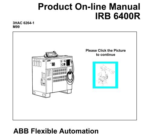
3HAC 6264-1<br />
M99<br />
<strong>Product</strong> <strong>On</strong>-<strong>line</strong> <strong>Manual</strong><br />
<strong>IRB</strong> <strong>6400R</strong><br />
ABB Flexible Automation<br />
Please Click the Picture<br />
to continue
The information in this document is subject to change without notice and should not be construed as a<br />
commitment by ABB Robotics <strong>Product</strong>s AB. ABB Robotics <strong>Product</strong>s AB assumes no responsibility for<br />
any errors that may appear in this document.<br />
In no event shall ABB Robotics <strong>Product</strong>s AB be liable for incidental or consequential damages arising<br />
from use of this document or of the software and hardware described in this document.<br />
This document and parts thereof must not be reproduced or copied without<br />
ABB Robotics <strong>Product</strong>s AB´s written permission, and contents thereof must not be imparted to a third<br />
party nor be used for any unauthorized purpose. Contravention will be prosecuted.<br />
Additional copies of this document may be obtained from ABB Robotics <strong>Product</strong>s AB at its then current<br />
charge.<br />
© ABB Robotics <strong>Product</strong>s AB<br />
Article number: 3HAC 2914-1<br />
Issue: M98<br />
ABB Robotics <strong>Product</strong>s AB<br />
S-721 68 Västerås<br />
Sweden
ABB Flexible Automation AB<br />
<strong>Product</strong> <strong>Manual</strong> <strong>IRB</strong> <strong>6400R</strong> M99, <strong>On</strong>-<strong>line</strong> <strong>Manual</strong><br />
MAIN MENU<br />
Introduction Installation and Commissioning<br />
<strong>Product</strong> Specification <strong>IRB</strong> <strong>6400R</strong> Maintenance<br />
<strong>Product</strong> Specification RobotWare Troubleshooting Tools<br />
Safety Fault tracing guide<br />
CE-declaration Circuit Diagram<br />
Configuration List Repairs<br />
System Description Spare parts
Description<br />
20 <strong>Product</strong> Specification <strong>IRB</strong> 1400 M97A/BaseWare OS 3.0
CONTENTS<br />
Introduction<br />
1 How to use this <strong>Manual</strong>........................................................................................... 3<br />
2 What you must know before you use the Robot ................................................... 3<br />
3 Identification ............................................................................................................ 4<br />
Page<br />
<strong>Product</strong> <strong>Manual</strong> 1
Introduction<br />
2 <strong>Product</strong> <strong>Manual</strong>
Introduction<br />
1 How to use this <strong>Manual</strong><br />
Introduction<br />
This manual provides information on installation, preventive maintenance, troubleshooting<br />
and how to carry out repairs on the manipulator and controller. Its intended<br />
audience is trained maintenance personnel with expertise in both mechanical and<br />
electrical systems. The manual does not in any way assume to take the place of the<br />
maintenance course offered by ABB Flexible Automation.<br />
Anyone reading this manual should also have access to the User’s Guide.<br />
The chapter entitled System Description provides general information on the robot<br />
structure, such as its computer system, input and output signals, etc.<br />
How to assemble the robot and install all signals, etc., is described in the chapter on<br />
Installation and Commissioning.<br />
If an error should occur in the robot system, you can find out why it has happened in<br />
the chapter on Troubleshooting. If you receive an error message, you can also consult<br />
the chapter on System and Error Messages in the User’s Guide. It is very helpful to<br />
have a copy of the circuit diagram at hand when trying to locate cabling faults.<br />
Servicing and maintenance routines are described in the chapter on Maintenance.<br />
2 What you must know before you use the Robot<br />
• Normal maintenance and repair work usually only require standard tools. Some<br />
repairs, however, require specific tools. These repairs, and the type of tool required,<br />
are described in more detail in the chapter Repairs.<br />
• The power supply must always be switched off whenever work is carried out in the<br />
controller cabinet. Note that even though the power is switched off, the orangecoloured<br />
cables may be live. The reason for this is that these cables are connected to<br />
external equipment and are consequently not affected by the mains switch on the<br />
controller.<br />
• Circuit boards - printed boards and components - must never be handled without<br />
Electro-Static Discharge (ESD) protection in order not to damage them. Use the carry<br />
band located on the inside of the controller door.<br />
All personnel working with the robot system must be very familiar with the safety<br />
regulations out<strong>line</strong>d in the chapter on Safety. Incorrect operation can damage the<br />
robot or injure someone.<br />
<strong>Product</strong> <strong>Manual</strong> 3
Introduction<br />
3 Identification<br />
<strong>IRB</strong> 140(0)<br />
Identification plates indicating the type of robot and serial number, etc., are located on<br />
the manipulator (see Figure 1) and on the front of the controller (see Figure 2).<br />
The BaseWare O.S diskettes are also marked with serial number (see Figure 3).<br />
Note! The identification plates and label shown in the figures below, only serves as<br />
examples. For exact identification see plates on your robot in question.<br />
<strong>IRB</strong> 640<br />
ABB Robotics <strong>Product</strong>s AB<br />
S-721 68 Västerås Sweden Made in Sweden<br />
Type:<br />
Robot version:<br />
Man. order:<br />
Nom. load<br />
Serial. No:<br />
Date of manufacturing:<br />
Net weight<br />
2,5-150 : 1910 kg<br />
<strong>IRB</strong> 2400<br />
<strong>IRB</strong> 340<br />
<strong>IRB</strong> <strong>6400R</strong> M99<br />
<strong>IRB</strong> 6400/2.5-150<br />
XXXXXX<br />
See instructions<br />
64-15XXX<br />
1999-XX-XX<br />
<strong>IRB</strong> 4400<br />
Identification plate showing<br />
the <strong>IRB</strong> <strong>6400R</strong> / M99<br />
<strong>IRB</strong> <strong>6400R</strong><br />
<strong>IRB</strong> 840/A<br />
Figure 1 Examples of identification plate and its location on different manipulator types.<br />
4 <strong>Product</strong> <strong>Manual</strong>
.<br />
Figure 2 Identification plate on the controller.<br />
64-00000<br />
System Key S4C 3.1<br />
Program No 3 HAB2390-1/03<br />
Boot disk 1 (1)<br />
Property of ABB Västerås/Sweden. All rights reserved. Reproduction,<br />
modification, use or disclosure to third parties without express authority<br />
is strictly forbidden. Copyright 1993. Restricted to be used in the<br />
controller(s) with the serial no as marked on disk.<br />
ABB Robotics <strong>Product</strong>s AB<br />
Figure 3 Example of a label on a BaseWare O.S diskette.<br />
ABB Robotics <strong>Product</strong>s AB<br />
S-721 68 Västerås Sweden Made in Sweden<br />
Type:<br />
<strong>IRB</strong> <strong>6400R</strong> M99<br />
Robot version:<br />
<strong>IRB</strong> <strong>6400R</strong>/2.5-150<br />
Voltage: 3 x 400 V Frequency: 50-60 Hz<br />
Power:<br />
7.2 kVA<br />
Man. order:<br />
XXXXXX<br />
Re.No:<br />
RXXXXXXXXXX<br />
Serial. No:<br />
64-XXXXX<br />
Date of manufacturing: 1998-XX-XX<br />
Net weight:<br />
240 kg<br />
Introduction<br />
<strong>Product</strong> <strong>Manual</strong> 5
Introduction<br />
6 <strong>Product</strong> <strong>Manual</strong>
CONTENTS<br />
<strong>Product</strong> Specification <strong>IRB</strong> <strong>6400R</strong><br />
1 Introduction ..................................................................................................................... 3<br />
2 Description....................................................................................................................... 5<br />
2.1 Structure.................................................................................................................. 5<br />
2.2 Safety/Standards ..................................................................................................... 6<br />
2.3 Operation ................................................................................................................ 7<br />
2.4 Installation .............................................................................................................. 9<br />
2.5 Programming .......................................................................................................... 9<br />
2.6 Automatic Operation .............................................................................................. 11<br />
2.7 Maintenance and Troubleshooting ......................................................................... 12<br />
2.8 Robot Motion.......................................................................................................... 14<br />
2.9 External Axes ......................................................................................................... 16<br />
2.10 Inputs and Outputs................................................................................................ 17<br />
2.11 Communication..................................................................................................... 17<br />
2.12 Spotweld Harness (option) ................................................................................... 18<br />
3 Technical specification .................................................................................................... 19<br />
3.1 Structure.................................................................................................................. 19<br />
3.2 Safety/Standards ..................................................................................................... 21<br />
3.3 Operation ................................................................................................................ 22<br />
3.4 Installation .............................................................................................................. 23<br />
3.5 Programming .......................................................................................................... 35<br />
3.6 Automatic Operation .............................................................................................. 39<br />
3.7 Maintenance and Troubleshooting ......................................................................... 39<br />
3.8 Robot Motion.......................................................................................................... 40<br />
3.9 External Axes ......................................................................................................... 42<br />
3.10 Inputs and Outputs................................................................................................ 43<br />
3.11 Communication..................................................................................................... 47<br />
3.12 Spotweld Harness (option) ................................................................................... 48<br />
4 Specification of Variants and Options........................................................................... 49<br />
5 Accessories ....................................................................................................................... 67<br />
6 Index................................................................................................................................. 69<br />
Page<br />
<strong>Product</strong> Specification <strong>IRB</strong> <strong>6400R</strong> M99/BaseWare OS 3.2 1
<strong>Product</strong> Specification <strong>IRB</strong> <strong>6400R</strong><br />
2 <strong>Product</strong> Specification <strong>IRB</strong> <strong>6400R</strong> M99/BaseWare OS 3.2
1 Introduction<br />
Introduction<br />
Thank you for your interest in the <strong>IRB</strong> <strong>6400R</strong>. This manual will give you an overview<br />
of the characteristics and performance of the robot.<br />
<strong>IRB</strong> <strong>6400R</strong> is a 6-axis industrial robot, designed specifically for manufacturing<br />
industries that use flexible robot-based automation. The robot has an open structure<br />
that is specially adapted for flexible use, and can communicate extensively with<br />
external systems.<br />
The <strong>IRB</strong> <strong>6400R</strong> comes in several different versions, with handling capacities of up to<br />
200 kg, a maximum reach of 3 m, floor-mounted manipulators as well as manipulators<br />
for harsh environments.<br />
Extra equipment, such as transformers and valve packages, can be placed on the upper<br />
arm or on the frame of axis 1 (see Chapter 3.4).<br />
The robot can be supplied with an integrated spot welding harness as well as a<br />
mechanical support for externally mounted process solutions.<br />
The robot is equipped with an operating system called BaseWare OS. BaseWare OS<br />
controls every aspect of the robot, like motion control, development and execution of<br />
application programs, communication etc.<br />
The functions in this document are all included in BaseWare OS, if not otherwise<br />
specified. For additional functionality the robot can be equipped with optional software<br />
for application support - spot welding, gluing etc., communication features - network<br />
communication - and advanced functions - multitasking, sensor control etc. For a<br />
complete description of optional software, see the <strong>Product</strong> Specification RobotWare.<br />
All the features are not described in this document. For a more complete and detailed<br />
description, please see the User’s Guide, RAPID Reference <strong>Manual</strong> and <strong>Product</strong><br />
<strong>Manual</strong>, or contact your nearest ABB Flexible Automation Centre.<br />
Accessories, such as track motion, motors for external axes, cabling for spot welding<br />
guns, and tool systems with tool exchangers, have been specially adapted for use with<br />
the <strong>IRB</strong> <strong>6400R</strong> (see Chapter 5).<br />
Different robot versions<br />
The <strong>IRB</strong> <strong>6400R</strong>, as mentioned above, is available in several different versions.<br />
The following different robot types are available:<br />
<strong>IRB</strong> <strong>6400R</strong>/2.5-120<br />
<strong>IRB</strong> <strong>6400R</strong>/2.5-150<br />
<strong>IRB</strong> <strong>6400R</strong>/2.5-200<br />
<strong>IRB</strong> <strong>6400R</strong>/2.8-150<br />
<strong>IRB</strong> <strong>6400R</strong>/2.8-200<br />
<strong>IRB</strong> <strong>6400R</strong>/3.0-100<br />
<strong>Product</strong> Specification <strong>IRB</strong> <strong>6400R</strong> M99/BaseWare OS 3.2 3
Introduction<br />
Definition of version designation<br />
<strong>IRB</strong> <strong>6400R</strong> Mounting/ Reach - Handling capacity<br />
How to use this manual<br />
The characteristics of the robot are described in Chapter 2: Description.<br />
The most important technical data is listed in Chapter 3: Technical specification.<br />
Note that the sections in chapters 2 and 3 are related to each other. For example, in<br />
section 2.2 you can find an overview of safety and standards, in section 3.2 you can find<br />
more detailed information.<br />
To make sure that you have ordered a robot with the correct functionality, see<br />
Chapter 4: Specification of Variants and Options.<br />
In Chapter 5 you will find accessories for the robot.<br />
Chapter 6 contains an Index, to make things easier to find.<br />
Other manuals<br />
Prefix Description<br />
Mounting - Floor-mounted manipulator<br />
Reach x.x Indicates the maximum reach at wrist centre (m)<br />
Handling capacity yyy Indicates the maximum handling capacity (kg)<br />
The User’s Guide is a reference manual with step by step instructions on how to<br />
perform various tasks.<br />
The programming language is described in the RAPID Reference <strong>Manual</strong>.<br />
The <strong>Product</strong> <strong>Manual</strong> describes how to install the robot, as well as maintenance<br />
procedures and troubleshooting.<br />
The <strong>Product</strong> Specification RobotWare describes the software options.<br />
4 <strong>Product</strong> Specification <strong>IRB</strong> <strong>6400R</strong> M99/BaseWare OS 3.2
2 Description<br />
2.1 Structure<br />
The robot is made up of two main parts: a manipulator and a controller.<br />
Figure 1 The <strong>IRB</strong> <strong>6400R</strong> manipulator has 6 axes.<br />
Teach pendant<br />
Mains switch<br />
Axis 3<br />
Axis 4<br />
Axis 2<br />
Axis 1<br />
Axis 5<br />
Axis 6<br />
Operator´s panel<br />
Disk drive<br />
Description<br />
Figure 2 The controller is specifically designed to control robots, which means that optimal<br />
performance and functionality is achieved.<br />
The controller contains the electronics required to control the manipulator, external<br />
axes and peripheral equipment.<br />
<strong>Product</strong> Specification <strong>IRB</strong> <strong>6400R</strong> M99/BaseWare OS 3.2 5
Description<br />
2.2 Safety/Standards<br />
The robot complies fully with the health and safety standards specified in the EEC’s<br />
Machinery Directives. For other safety standards, see chapter 3.2 on page 21.<br />
The robot is designed with absolute safety in mind. It has a dedicated safety system<br />
based on a two-channel circuit which is monitored continuously. If any component<br />
fails, the electrical power supplied to the motors shuts off and the brakes engage.<br />
Safety category 3<br />
Malfunction of a single component, such as a sticking relay, will be detected at the next<br />
MOTOR OFF/MOTOR ON operation. MOTOR ON is then prevented and the faulty<br />
section is indicated. This complies with category 3 of EN 954-1, Safety of machinery -<br />
safety related parts of control systems - Part 1.<br />
Selecting the operating mode<br />
The robot can be operated either manually or automatically. In manual mode, the robot<br />
can only be operated via the teach pendant, i.e. not by any external equipment.<br />
Reduced speed<br />
In manual mode, the speed is limited to a maximum of 250 mm/s (600 inch/min.).<br />
The speed limitation applies not only to the TCP (Tool Centre point), but to all parts of<br />
the robot. It is also possible to monitor the speed of equipment mounted on the robot.<br />
Three position enabling device<br />
The enabling device on the teach pendant must be used to move the robot when in<br />
manual mode. The enabling device consists of a switch with three positions, meaning<br />
that all robot movements stop when either the enabling device is pushed fully in, or<br />
when it is released completely. This makes the robot safer to operate.<br />
Safe manual movement<br />
The robot is moved using a joystick instead of the operator having to look at the teach<br />
pendant to find the right key.<br />
Over-speed protection<br />
The speed of the robot is monitored by two independent computers.<br />
Emergency stop<br />
There is one emergency stop push button on the controller and another on the teach<br />
pendant. Additional emergency stop buttons can be connected to the robot’s safety<br />
chain circuit.<br />
Safeguarded space stop<br />
The robot has a number of electrical inputs which can be used to connect external safety<br />
equipment, such as safety gates and light curtains. This allows the robot’s safety<br />
functions to be activated both by peripheral equipment and by the robot itself.<br />
Delayed safeguarded space stop<br />
A delayed stop gives a smooth stop. The robot stops in the same way as at a normal<br />
program stop with no deviation from the programmed path. After approx. 1 second the<br />
power supplied to the motors shuts off.<br />
Collision detection<br />
In case an unexpected mechanical disturbance like a collision, electrode stik etc<br />
appears, the robot will stop and slightly back off from its stop position.<br />
6 <strong>Product</strong> Specification <strong>IRB</strong> <strong>6400R</strong> M99/BaseWare OS 3.2
2.3 Operation<br />
Display<br />
Description<br />
Restricting the working space<br />
The movement of each axis can be restricted using software limits. Axes 1-3 can also<br />
be restricted by means of mechanical stops.<br />
Hold-to-run control<br />
“Hold-to-run” means that you must depress the start button in order to move the robot. When<br />
the button is released the robot will stop. The hold-to-run function makes program testing<br />
safer.<br />
Fire safety<br />
Both the manipulator and control system comply with UL’s (Underwriters Laboratory)<br />
tough requirements for fire safety.<br />
Safety lamp<br />
As an option, the robot can be equipped with a safety lamp mounted on the manipulator.<br />
This is activated when the motors are in the MOTORS ON state.<br />
All operations and programming can be carried out using the portable teach pendant<br />
(see Figure 3) and the operator’s panel (see Figure 5).<br />
1<br />
2<br />
P1 P2<br />
P3<br />
7 8 9<br />
4 5 6<br />
2 3<br />
0<br />
Figure 3 The teach pendant is equipped with a large display, which displays prompts,<br />
information, error messages and other information in plain English.<br />
Information is presented on a display using windows, pull-down menus, dialogs and<br />
function keys. No previous programming or computer experience is required to learn<br />
how to operate the robot. All operations can be carried out from the teach pendant,<br />
which means that an additional keyboard is not required. All information, including the<br />
complete programming language, is in English or, if preferred, some other major<br />
language. (For a list of languages, see <strong>Product</strong> Specification RobotWare).<br />
<strong>Product</strong> Specification <strong>IRB</strong> <strong>6400R</strong> M99/BaseWare OS 3.2 7<br />
1<br />
Joystick<br />
Emergency<br />
stop button
Description<br />
I/O list<br />
Figure 4 Window for manual operation of input and output signals.<br />
Using the joystick, the robot can be manually jogged (moved). The user determines the<br />
speed of this movement; large deflections of the joystick will move the robot quickly,<br />
smaller deflections will move it more slowly.<br />
The robot supports different user tasks, with dedicated windows for:<br />
Operator’s panel<br />
Motors <strong>On</strong> button<br />
and indicating lamp<br />
Emergency stop<br />
File Edit View<br />
1 Goto ...<br />
Inputs/Outputs 2 Goto Top<br />
3 Goto Bottom<br />
Name<br />
Value<br />
di1<br />
di2<br />
grip1<br />
grip2<br />
clamp3B<br />
feeder<br />
progno<br />
1 0<br />
- <strong>Product</strong>ion<br />
- Programming<br />
- System setup<br />
- Service and installation<br />
1<br />
0<br />
1<br />
0<br />
1<br />
1<br />
13<br />
Figure 5 The operating mode is selected using the operator’s panel on the controller.<br />
8 <strong>Product</strong> Specification <strong>IRB</strong> <strong>6400R</strong> M99/BaseWare OS 3.2<br />
4(6)<br />
Menu keys<br />
Menu<br />
Line indicator<br />
Cursor<br />
Function keys<br />
Operating mode selector<br />
Duty time counter
Description<br />
Using a key switch, the robot can be locked in two or three different operating modes<br />
depending on chosen mode selector:<br />
100%<br />
2.4 Installation<br />
2.5 Programming<br />
• Automatic mode: Running production<br />
• <strong>Manual</strong> mode at reduced speed: Programming and setup<br />
Max. speed: 250 mm/s (600 inches/min.)<br />
• <strong>Manual</strong> mode at full speed (option): Testing at full program speed<br />
Equipped with this mode, the robot is<br />
not approved according to ANSI/UL<br />
Both the operator’s panel and the teach pendant can be mounted externally, i.e. outside<br />
the cabinet. The robot can then be controlled from there.<br />
The robot can be remotely controlled from a computer, PLC or from a customer’s<br />
panel, using serial communication or digital system signals.<br />
For more information on how to operate the robot, see the User’s Guide.<br />
The robot has a standard configuration and can be operated immediately after<br />
installation. Its configuration is displayed in plain language and can easily be changed<br />
using the teach pendant. The configuration can be stored on a diskette and/or<br />
transferred to other robots that have the same characteristics.<br />
All the versions of <strong>IRB</strong> <strong>6400R</strong> are designed for floor mounting. Depending on the<br />
robot version an end effector of max. weight 100 to 200 kg, including payload, can be<br />
mounted on the mounting flange (axis 6). Load diagram, see chapter 3.4.<br />
Extra loads (valve packages, transformers) can be mounted on the upper arm. <strong>On</strong> all<br />
versions an extra load can also be mounted on the frame of axis 1. Holes for extra<br />
equipment are described in chapter 3.4.<br />
The working range of axes 1-3 can be limited by mechanical stops. Position switches<br />
can be supplied on axes 1-3 for position indication of the manipulator.<br />
Programming the robot involves choosing instructions and arguments from lists of<br />
appropriate alternatives. Users do not need to remember the format of instructions,<br />
since they are prompted in plain English. “See and pick” is used instead of “remember<br />
and type”.<br />
The programming environment can be easily customized using the teach pendant.<br />
- Shop floor language can be used to name programs, signals, counters, etc.<br />
- New instructions can be easily written.<br />
- The most common instructions can be collected in easy-to-use pick lists.<br />
- Positions, registers, tool data, or other data, can be created.<br />
<strong>Product</strong> Specification <strong>IRB</strong> <strong>6400R</strong> M99/BaseWare OS 3.2 9
Description<br />
Programs, parts of programs and any modifications can be tested immediately without<br />
having to translate (compile) the program.<br />
The program is stored as a normal PC text file, which means that it can be edited using<br />
a standard PC.<br />
Movements<br />
A sequence of movements is programmed as a number of partial movements between<br />
the positions to which you want the robot to move.<br />
The end position of a movement is selected either by manually jogging the robot to the<br />
desired position with the joystick, or by referring to a previously defined position.<br />
The exact position can be defined (see Figure 6) as:<br />
- a stop point, i.e. the gantry robot reaches the programmed position<br />
or<br />
- a fly-by point, i.e. the robot passes close to the programmed position. The size<br />
of the deviation is defined independently for the TCP, the tool orientation and<br />
the external axes.<br />
Figure 6 The fly-by point reduces the cycle time since the robot does not have to stop at<br />
the programmed point. The path is speed independent.<br />
The velocity may be specified in the following units:<br />
- mm/s<br />
- seconds (time it takes to reach the next programmed position)<br />
- degrees/s (for reorientation of the tool or for rotation of an external axis)<br />
Program management<br />
Stop point Fly-by point<br />
User-definable distance (in mm)<br />
For convenience, the programs can be named and stored in different directories.<br />
Areas of the robot’s program memory can also be used for program storage. This<br />
provides fast memory for program storage. These can then be automatically<br />
downloaded using a program instruction. The complete program or parts of programs<br />
can be transferred to/from a diskette.<br />
Programs can be printed on a printer connected to the robot, or transferred to a PC<br />
where they can be edited or printed later.<br />
10 <strong>Product</strong> Specification <strong>IRB</strong> <strong>6400R</strong> M99/BaseWare OS 3.2
Editing programs<br />
Description<br />
Programs can be edited using standard editing commands, i.e. “cut-and-paste”, copy,<br />
delete, find and change, undo etc. Individual arguments in an instruction can also be<br />
edited using these commands.<br />
No reprogramming is necessary when processing left-hand and right-hand parts, since<br />
the program can be mirrored in any plane.<br />
A robot position can easily be changed either by<br />
- jogging the robot with the joystick to a new position and then pressing the<br />
“ModPos” key (this registers the new position)<br />
or by<br />
- entering or modifying numeric values.<br />
To prevent unauthorised personnel from making program changes, passwords can be<br />
used.<br />
Testing programs<br />
Several helpful functions can be used when testing programs. For example, it is<br />
possible to<br />
- start from any instruction<br />
- execute an incomplete program<br />
- run a single cycle<br />
- execute forward/backward step-by-step<br />
- simulate wait conditions<br />
- temporarily reduce the speed<br />
- change a position<br />
- tune (displace) a position during program execution.<br />
For more information, see the User’s Guide and RAPID Reference <strong>Manual</strong>.<br />
2.6 Automatic Operation<br />
A dedicated production window with commands and information required by the<br />
operator is automatically displayed during automatic operation.<br />
The operation procedure can be customised to suit the robot installation by means of<br />
user-defined operating dialogs.<br />
<strong>Product</strong> Specification <strong>IRB</strong> <strong>6400R</strong> M99/BaseWare OS 3.2 11
Description<br />
Select program to run:<br />
Figure 7 The operator dialogs can be easily customised.<br />
A special input can be set to order the robot to go to a service position. After service,<br />
the robot is ordered to return to the programmed path and continue program execution.<br />
You can also create special routines that will be automatically executed when the power<br />
is switched on, at program start and on other occasions. This allows you to customise<br />
each installation and to make sure that the robot is started up in a controlled way.<br />
The robot is equipped with absolute measurement, making it possible to operate the<br />
robot directly when the power is switched on. For your convenience, the robot saves<br />
the used path, program data and configuration parameters so that the program can be<br />
easily restarted from where you left off. Digital outputs are also set automatically to the<br />
value prior to the power failure.<br />
2.7 Maintenance and Troubleshooting<br />
Front A Front B Front C Other SERVICE<br />
The robot requires only a minimum of maintenance during operation. It has been<br />
designed to make it as easy to service as possible:<br />
- The controller is enclosed, which means that the electronic circuitry is protected<br />
when operating in a normal workshop environment.<br />
- Maintenance-free AC motors are used.<br />
- Liquid grease or oil is used for the gear boxes.<br />
- The cabling is routed for longevity, and in the unlikely event of a failure, its<br />
modular design makes it easy to change.<br />
- It has a program memory “battery low” alarm.<br />
The robot has several functions to provide efficient diagnostics and error reports:<br />
- It performs a self-test when power on is set.<br />
- Errors are indicated by a message displayed in plain language.<br />
The message includes the reason for the fault and suggests recovery action.<br />
- A board error is indicated by a LED on the faulty unit.<br />
12 <strong>Product</strong> Specification <strong>IRB</strong> <strong>6400R</strong> M99/BaseWare OS 3.2
Description<br />
- Faults and major events are logged and time-stamped. This makes it possible to<br />
detect error chains and provides the background for any downtime. The log can<br />
be read on the teach pendant display, stored in a file or printed on a printer.<br />
- There are commands and service programs in RAPID to test units and<br />
functions.<br />
Most errors detected by the user program can also be reported to and handled by the<br />
standard error system. Error messages and recovery procedures are displayed in plain<br />
language.<br />
<strong>Product</strong> Specification <strong>IRB</strong> <strong>6400R</strong> M99/BaseWare OS 3.2 13
Description<br />
2.8 Robot Motion<br />
Floor-mounting<br />
Dimensions apply to<br />
<strong>IRB</strong> <strong>6400R</strong>/ 3.0-100<br />
Motion performance<br />
1229<br />
Figure 8 Working space of <strong>IRB</strong> <strong>6400R</strong> (dimensions in mm).<br />
The QuickMoveTM concept means that a self-optimizing motion control is used.<br />
The robot automatically optimizes the servo parameters to achieve the best possible<br />
performance throughout the cycle - based on load properties, location in working area,<br />
velocity and direction of movement.<br />
- No parameters have to be adjusted to achieve correct path, orientation and<br />
velocity.<br />
- Maximum acceleration is always obtained (acceleration can be reduced, e.g.<br />
when handling fragile parts).<br />
- The number of adjustments that have to be made to achieve the shortest possible<br />
cycle time is minimized.<br />
The TrueMoveTM concept means that the programmed path is followed – regardless of<br />
the speed or operating mode – even after an emergency stop, a safeguarded stop, a<br />
process stop, a program stop or a power failure.<br />
The robot can, in a controlled way, pass through singular points, i.e. points where two<br />
axes coincide.<br />
14 <strong>Product</strong> Specification <strong>IRB</strong> <strong>6400R</strong> M99/BaseWare OS 3.2<br />
2999<br />
848 2859
Coordinate systems<br />
Z<br />
X<br />
Z<br />
Y<br />
Y<br />
X<br />
X<br />
World coordinates<br />
Base coordinates<br />
Y<br />
Tool coordinates<br />
Z<br />
Tool Centre Point (TCP)<br />
Object<br />
Description<br />
Figure 9 The coordinate systems, used to make jogging and off-<strong>line</strong> programming easier.<br />
The world coordinate system defines a reference to the floor, which is the starting<br />
point for the other coordinate systems. Using this coordinate system, it is possible to<br />
relate the robot position to a fixed point in the workshop. The world coordinate system<br />
is also very useful when two robots work together or when using a robot carrier.<br />
The base coordinate system is attached to the base mounting surface of the robot.<br />
The tool coordinate system specifies the tool’s centre point and orientation.<br />
The user coordinate system specifies the position of a fixture or workpiece<br />
manipulator.<br />
The object coordinate system specifies how a workpiece is positioned in a fixture or<br />
workpiece manipulator.<br />
The coordinate systems can be programmed by specifying numeric values or jogging<br />
the robot through a number of positions (the tool does not have to be removed).<br />
Each position is specified in object coordinates with respect to the tool’s position and<br />
orientation. This means that even if a tool is changed because it is damaged, the old<br />
program can still be used, unchanged, by making a new definition of the tool.<br />
If a fixture or workpiece is moved, only the user or object coordinate system has to be<br />
redefined.<br />
<strong>Product</strong> Specification <strong>IRB</strong> <strong>6400R</strong> M99/BaseWare OS 3.2 15<br />
Z<br />
User<br />
coordinates<br />
Y<br />
X<br />
Z<br />
coordinates<br />
Y<br />
X
Description<br />
Stationary TCP<br />
When the robot is holding a work object and working on a stationary tool, it is possible<br />
to define a TCP for that tool. When that tool is active, the programmed path and speed<br />
are related to the work object.<br />
Program execution<br />
Jogging<br />
The robot can move in any of the following ways:<br />
- Joint motion (all axes move individually and reach<br />
the programmed position at the same time)<br />
- Linear motion (the TCP moves in a <strong>line</strong>ar path)<br />
- Circle motion (the TCP moves in a circular path)<br />
Soft servo - allowing external forces to cause deviation from programmed position -<br />
can be used as an alternative to mechanical compliance in grippers, where imperfection<br />
in processed objects can occur.<br />
If the location of a workpiece varies from time to time, the robot can find its position<br />
by means of a digital sensor. The robot program can then be modified in order to adjust<br />
the motion to the location of the part.<br />
The robot can be manually operated in any one of the following ways:<br />
- Axis-by-axis, i.e. one axis at a time<br />
- Linearly, i.e. the TCP moves in a <strong>line</strong>ar path (relative to one of the coordinate<br />
systems mentioned above)<br />
- Reoriented around the TCP<br />
It is possible to select the step size for incremental jogging. Incremental jogging can be<br />
used to position the robot with high precision, since the robot moves a short distance<br />
each time the joystick is moved.<br />
During manual operation, the current position of the robot and the external axes can be<br />
displayed on the teach pendant.<br />
2.9 External Axes<br />
The robot can control up to six external axes. These axes are programmed and moved<br />
using the teach pendant in the same way as the robot’s axes.<br />
The external axes can be grouped into mechanical units to facilitate, for example,<br />
the handling of robot carriers, workpiece manipulators, etc.<br />
The robot motion can be simultaneously coordinated with for example, a one-axis<br />
<strong>line</strong>ar robot carrier and a rotational external axis.<br />
A mechanical unit can be activated or deactivated to make it safe when, for example,<br />
manually changing a workpiece located on the unit. In order to reduce investment costs,<br />
any axes that do not have to be active at the same time, can share the same drive unit.<br />
16 <strong>Product</strong> Specification <strong>IRB</strong> <strong>6400R</strong> M99/BaseWare OS 3.2
2.10 Inputs and Outputs<br />
Description<br />
A distributed I/O system is used, which makes it possible to mount the I/O units either<br />
inside the cabinet or outside the cabinet with a cable connecting the I/O unit to the<br />
cabinet.<br />
A number of different input and output units can be installed:<br />
- Digital inputs and outputs.<br />
- Analog inputs and outputs.<br />
- Remote I/O for Allen-Bradley PLC.<br />
- Interbus-S Slave.<br />
- Profibus DP Slave.<br />
The inputs and outputs can be configured to suit your installation:<br />
- Each signal and unit can be given a name, e.g. gripper, feeder.<br />
- I/O mapping (i.e. a physical connection for each signal).<br />
- Polarity (active high or low).<br />
- Cross connections.<br />
- Up to 16 digital signals can be grouped together and used as if they were a<br />
single signal when, for example, entering a bar code.<br />
Signals can be assigned to special system functions, such as program start, so as to be<br />
able to control the robot from an external panel or PLC.<br />
The robot can work as a PLC by monitoring and controlling I/O signals:<br />
- I/O instructions can be executed concurrent to the robot motion.<br />
- Inputs can be connected to trap routines. (When such an input is set, the<br />
trap routine starts executing. Following this, normal program execution<br />
resumes. In most cases, this will not have any visible effect on the robot motion,<br />
i.e. if a limited number of instructions are executed in the trap routine.)<br />
- Background programs (for monitoring signals, for example) can be<br />
run in parallel with the actual robot program. Requires Multitasking option, see<br />
<strong>Product</strong> Specification RobotWare.<br />
<strong>Manual</strong> functions are available to:<br />
- List all the signal values.<br />
- Create your own list of your most important signals.<br />
- <strong>Manual</strong>ly change the status of an output signal.<br />
- Print signal information on a printer.<br />
I/O signals can also be routed parallel or serial to connectors on the upper arm of the<br />
robot.<br />
2.11 Communication<br />
The robot can communicate with computers or other equipment via RS232/RS422<br />
serial channels or via Ethernet. However this requires optional software, see <strong>Product</strong><br />
Specification RobotWare.<br />
<strong>Product</strong> Specification <strong>IRB</strong> <strong>6400R</strong> M99/BaseWare OS 3.2 17
Description<br />
2.12 Spotweld Harness (option)<br />
The robot can be supplied with an integrated spot welding harness as well as a<br />
mechanical support for externally mounted process solutions.<br />
The integrated spotwelding harness is used to supply primary current and cooling water<br />
to the upper arm. Connections at the manipulator base and the upper arm housing.<br />
For more information, see section 3.12 on page 48 and Figure 31 and Figure 32.<br />
18 <strong>Product</strong> Specification <strong>IRB</strong> <strong>6400R</strong> M99/BaseWare OS 3.2
3 Technical specification<br />
3.1 Structure<br />
Applies to standard and Foundry versions unless otherwise stated.<br />
Weight: Manipulator <strong>IRB</strong> <strong>6400R</strong> /2.5-120 2060 kg<br />
<strong>IRB</strong> <strong>6400R</strong> /2.5-150 2060 kg<br />
<strong>IRB</strong> <strong>6400R</strong> /2.5-200 2230 kg<br />
<strong>IRB</strong> <strong>6400R</strong> /2.8-150 2240 kg<br />
<strong>IRB</strong> <strong>6400R</strong> /2.8-200 2390 kg<br />
<strong>IRB</strong> <strong>6400R</strong> /3.0-100 2250 kg<br />
Controller 240 kg<br />
Volume: Controller 950 x 800 x 540 mm<br />
Technical specification<br />
Airborne noise level:<br />
The sound pressure level outside < 70 dB (A) Leq (acc. to<br />
the working space Machinery directive 98/37/EEC)<br />
50<br />
540<br />
250<br />
Lifting points<br />
for forklift<br />
200<br />
950<br />
980 *<br />
Figure 10 View of the controller from the front, from above and from the side (dimensions in mm).<br />
<strong>Product</strong> Specification <strong>IRB</strong> <strong>6400R</strong> M99/BaseWare OS 3.2 19<br />
800<br />
* Castor wheels<br />
800<br />
Extended cover<br />
Option 123<br />
Cabinet extension<br />
Option 124<br />
500<br />
500
Technical specification<br />
1050<br />
2240<br />
<strong>IRB</strong> <strong>6400R</strong> /2.5-120, /2.5-150, /2.5-200, /2.8-150, /2.8-200 and /3.0-100<br />
225<br />
1280<br />
800<br />
1070<br />
400<br />
240<br />
400<br />
1175 (/2.5-X)<br />
1520 (/2.8-X)<br />
1725 (/3.0-X)<br />
2285 (/2.5-X)<br />
R 530 (/2.5-120, /2.5-150)<br />
R 630 (/2.5-200, /2.8-150, /3.0-100)<br />
R 700 (/2.8-200)<br />
Rmax=700<br />
Fork lift device<br />
Figure 11 View of the manipulator from the side, rear and above (dimensions in mm).<br />
20 <strong>Product</strong> Specification <strong>IRB</strong> <strong>6400R</strong> M99/BaseWare OS 3.2<br />
332<br />
200<br />
250<br />
765<br />
780<br />
1050
3.2 Safety/Standards<br />
Technical specification<br />
The robot conforms to the following standards:<br />
EN 292-1 Safety of machinery, terminology<br />
EN 292-2 Safety of machinery, technical specifications<br />
EN 954-1 Safety of machinery, safety related parts of control<br />
systems<br />
EN 60204 1<br />
Electrical equipment of industrial machines<br />
IEC 204-1 Electrical equipment of industrial machines<br />
ISO 10218, EN 775 Manipulating industrial robots, safety<br />
ANSI/RIA 15.06/1992 Industrial robots, safety requirements<br />
ISO 9409-1 Manipulating industrial robots, mechanical<br />
interface<br />
ISO 9787 Manipulating industrial robots, coordinate systems<br />
and motions<br />
IEC 529 Degrees of protection provided by enclosures<br />
EN 50081-2 EMC, Generic emission<br />
EN 50082-2 EMC, Generic immunity<br />
ANSI/UL 1740-1996 (option) Standard for Industrial Robots and Robotic<br />
Equipment<br />
CAN/CSA Z 434-94 (option) Industrial Robots and Robot Systems - General<br />
Safety Requirements<br />
Safeguarded space stops via inputs<br />
External safety equipment can be connected to the robot’s two-channel emergency stop<br />
chain in several different ways (see Figure 12).<br />
Operating mode selector<br />
Auto mode<br />
safeguarded space stop<br />
Teach pendant<br />
Enabling device<br />
Technical specification<br />
3.3 Operation<br />
Window<br />
keys<br />
Display<br />
Menu keys<br />
Figure 13 The teach pendant is very easy to use since any functions provided via the function and<br />
menu keys are described in plain language. The remaining keys can perform only one<br />
function each.<br />
Display<br />
16 text <strong>line</strong>s with 40 characters per <strong>line</strong>.<br />
Motion keys<br />
Select the type of movement when jogging.<br />
Navigation keys<br />
Move the cursor and enter data.<br />
Menu keys<br />
Display pull-down menus.<br />
Function keys<br />
Select the commands used most often.<br />
1<br />
2<br />
P1 P2<br />
P3<br />
Function keys<br />
7 8 9<br />
4 5 6<br />
1<br />
Motion keys<br />
2 3<br />
0<br />
Navigation keys<br />
Hold-to-run<br />
Enabling<br />
device<br />
Window keys<br />
Display one of the robot’s various windows. These windows control a number of<br />
different functions:<br />
- Jog (manual operation)<br />
- Program, edit and test a program<br />
- <strong>Manual</strong> input/output management<br />
- File management<br />
- System configuration<br />
- Service and troubleshooting<br />
- Automatic operation<br />
User-defined keys (P1-P5)<br />
Five user-defined keys that can be configured to set or reset an output (e.g. open/close<br />
gripper) or to activate a system input (see chapter 3.10).<br />
22 <strong>Product</strong> Specification <strong>IRB</strong> <strong>6400R</strong> M99/BaseWare OS 3.2<br />
P5<br />
P4<br />
Joystick
3.4 Installation<br />
Operating requirements<br />
Protection standards IEC529<br />
Standard Manipulator IP54<br />
Wrist IP55<br />
Controller IP54<br />
Explosive environments<br />
The robot must not be located or operated in an explosive environment.<br />
Technical specification<br />
Ambient temperature<br />
Manipulator during operation +5 o C (41 o F) to +50 o C (122 o F)<br />
Controller during operation +5 o C (41 o F) to +52 o C (125 o F)<br />
Complete robot during transportation and storage, -25 o C (13 o F) to +55 o C (131 o F)<br />
for short periods (not exceeding 24 hours) up to +70 o C (158 o F)<br />
Relative humidity<br />
Complete robot during transportation and storage Max. 95% at constant temperature<br />
Complete robot during operation Max. 95% at constant temperature<br />
Power supply<br />
Mains voltage 200-600 V, 3p (3p + N for certain<br />
options, +10%,-15%<br />
Mains frequency<br />
Rated power:<br />
48.5 to 61.8 Hz<br />
<strong>IRB</strong> <strong>6400R</strong> 7.8 kVA (transformer size)<br />
External axes drives in separate cabinet 7.2 kVA (transformer size)<br />
Absolute measurement backup 1000 h (rechargeable battery)<br />
Configuration<br />
The robot is very flexible and can, by using the teach pendant, easily be configured to suit<br />
the needs of each user:<br />
Authorisation Password protection for configuration and program<br />
window<br />
Most common I/O User-defined lists of I/O signals<br />
Instruction pick list User-defined set of instructions<br />
Instruction builder User-defined instructions<br />
Operator dialogs Customised operator dialogs<br />
Language All text on the teach pendant can be displayed in<br />
several languages<br />
Date and time Calendar support<br />
Power on sequence Action taken when the power is switched on<br />
EM stop sequence Action taken at an emergency stop<br />
Main start sequence Action taken when the program is<br />
starting from the beginning<br />
Program start sequence Action taken at program start<br />
<strong>Product</strong> Specification <strong>IRB</strong> <strong>6400R</strong> M99/BaseWare OS 3.2 23
Technical specification<br />
Program stop sequence Action taken at program stop<br />
Change program sequence Action taken when a new program is loaded<br />
Working space Working space limitations<br />
External axes Number, type, common drive unit, mechanical units<br />
Brake delay time Time before brakes are engaged<br />
I/O signal Logical names of boards and signals, I/O mapping,<br />
cross connections, polarity, scaling, default value at<br />
start up, interrupts, group I/O<br />
Serial communication Configuration<br />
For a detailed description of the installation procedure, see the <strong>Product</strong> <strong>Manual</strong> -<br />
Installation and Commissioning.<br />
24 <strong>Product</strong> Specification <strong>IRB</strong> <strong>6400R</strong> M99/BaseWare OS 3.2
Mounting the manipulator<br />
Maximum load in relation to the base coordinate system.<br />
Endurance load Max. load at<br />
in operation emergency stop<br />
Force xy ±14000 N ±38000 N<br />
Force z 22000 ±8000 N 22000 ±19000 N<br />
Torque xy ±34000 Nm ±61000 Nm<br />
Torque z 7000 Nm ±15000 Nm<br />
317.34 (4x)<br />
243.5 (4x)<br />
(37.5°) (4x)<br />
B - B<br />
R 400<br />
A - A<br />
317.34<br />
Figure 14 Hole configuration (dimensions in mm).<br />
Technical specification<br />
B B<br />
A A<br />
∅ 0.4<br />
<strong>Product</strong> Specification <strong>IRB</strong> <strong>6400R</strong> M99/BaseWare OS 3.2 25<br />
(4x)<br />
243.5 (4x)<br />
(15°) (4x) 0<br />
Y<br />
Z<br />
∅ 53 (8x)<br />
∅ 28 (8x)<br />
15 +2<br />
100<br />
∅ 45 H9 (4x)<br />
+0.5<br />
0<br />
X
Technical specification<br />
Load diagrams<br />
Load diagram for <strong>IRB</strong> <strong>6400R</strong> /2.5-120 and /3.0-100<br />
(The curve for 120 kg is not valid for /3.0-100,<br />
max. handling capacity limited to 100 kg).<br />
0.9<br />
0.8<br />
0.7<br />
0.6<br />
0.5<br />
0.4<br />
0.3<br />
0.2<br />
0.1<br />
Z (m)<br />
75 kg<br />
100 kg<br />
120 kg<br />
45 kg<br />
60 kg<br />
30 kg<br />
0.1 0.2 0.3<br />
The load diagram is valid for J 0
Load diagram for <strong>IRB</strong> <strong>6400R</strong> /2.5-150 and /2.8-150<br />
0.9<br />
0.8<br />
0.7<br />
0.6<br />
0.5<br />
0.4<br />
0.3<br />
0.2<br />
0.1<br />
Z (m)<br />
75 kg<br />
100 kg<br />
125 kg<br />
150 kg<br />
0.1 0.2 0.3<br />
Technical specification<br />
Figure 16 Maximum weight permitted for load mounted on the mounting flange at different positions<br />
(centre of gravity).<br />
<strong>Product</strong> Specification <strong>IRB</strong> <strong>6400R</strong> M99/BaseWare OS 3.2 27<br />
0.4<br />
0.5 0.6 0.7<br />
The load diagram is valid for J 0
Technical specification<br />
Load diagram for <strong>IRB</strong> <strong>6400R</strong> /2.5-200 and /2.8-200<br />
0.9<br />
0.8<br />
0.7<br />
0.6<br />
0.5<br />
0.4<br />
0.3<br />
0.2<br />
0.1<br />
Z (m)<br />
100 kg<br />
125 kg<br />
150 kg<br />
175 kg<br />
200 kg<br />
0.1 0.2 0.3<br />
Figure 17 Maximum weight permitted for load mounted on the mounting flange at different positions<br />
(centre of gravity).<br />
28 <strong>Product</strong> Specification <strong>IRB</strong> <strong>6400R</strong> M99/BaseWare OS 3.2<br />
0.4<br />
0.5 0.6 0.7<br />
The load diagram is valid for J 0
Handling capacity for <strong>IRB</strong> <strong>6400R</strong> /2.8-150 in press-tending application<br />
Part<br />
Note! Option 090, Cooling for axis 1 motor, must be installed.<br />
Technical specification<br />
The weight and dimensions of the part and gripper are limited by the maximum static<br />
torque and moment of inertia.<br />
Figure 18 A-movement (inward movement).<br />
Part<br />
Figure 19 B-movement.<br />
Static torque: A-movement Axis 5 Ma 5 < 650 Nm<br />
B-movement Axis 4 Mb 4 < 650 Nm<br />
Moment of inertia: A-movement Axis 5, Ja 5 < 105 kgm 2<br />
Axis 6, Ja 6 < 120 kgm 2<br />
B-movement Axis 4, Jb 4 < 105 kgm 2<br />
Axis 5, Jb 5 < 120 kgm 2<br />
Approximations of M and J can be calculated using the following formula:<br />
Ma 5 = 9.81 • (m g • r + m p • s) (Nm)<br />
Mb 4 = 9.81 • (m g • (r + 0.2) + m p • (s + 0.2)) (Nm)<br />
Ja 5 = m g / 12 • c 2 + m g • r 2 + m p / 12 • a 2 + m p • s 2 (kgm 2 )<br />
Ja 6 = m g / 12 • c 2 + m g • r 2 + m p / 12 • (a 2 + b 2 ) + m p • s 2 (kgm 2 )<br />
Jb 4 = m g / 12 • c 2 + m g • (r + 0.2) 2 + m p / 12 • a 2 + m p • (s + 0.2) 2 (kgm 2 )<br />
Jb 5 = m g / 12 • c 2 + m g • (r + 0.2) 2 + m p / 12 • (a 2 + b 2 ) + m p • (s + 0.2) 2 (kgm 2 )<br />
m g = weight of gripper (kg) m p = weight of part (kg)<br />
Distances a, b, c, r and s (m) are shown in Figure 20.<br />
Press Press<br />
Movement mainly with axes 1 and 6<br />
<strong>Product</strong> Specification <strong>IRB</strong> <strong>6400R</strong> M99/BaseWare OS 3.2 29<br />
Part<br />
Wrist<br />
Wrist<br />
Press Press<br />
Part<br />
Movement mainly with axes 1, 2, 3 and 4
Technical specification<br />
Part<br />
Gripper<br />
m p<br />
Figure 20 Distances r and s (m).<br />
30 <strong>Product</strong> Specification <strong>IRB</strong> <strong>6400R</strong> M99/BaseWare OS 3.2<br />
m g<br />
A-movement, gripper perpendicular to axis 6<br />
Part<br />
Gripper<br />
B-movement, gripper parallel to axis 6<br />
Gripper<br />
Part<br />
a<br />
m g<br />
m p<br />
TCP 0<br />
b<br />
Dimensions of gripper and part<br />
s<br />
r<br />
r<br />
c<br />
s
Technical specification<br />
Mounting equipment<br />
Extra loads can be mounted on the upper arm and the frame. Definitions of distances<br />
and masses are shown in Figure 21 and Figure 22.<br />
The robot is supplied with holes for mounting extra equipment (see Figure 23).<br />
Upper arm - Balancing unit type A<br />
<strong>IRB</strong> <strong>6400R</strong> /2.5-120, /2.5-150, /2.5-200, /2.8-150 and /2.8-200<br />
Permitted extra load on upper arm plus the maximum handling weight<br />
(See Figure 21):<br />
M1 ≤50 kg with distance a ≤500 mm, centre of gravity in axis 3 extension<br />
or<br />
M2 ≤50 kg with distance b ≤400 mm<br />
or<br />
M3 ≤15 kg with distance c ≥300 mm<br />
If the handling weight is lower than the maximum weight, M1 alt. M2 can<br />
be increased as follows:<br />
(M1 alt. M2 + handling weight) ≤ (50 kg + max. handling weight).<br />
For example, if the handling weight for 2.5-150 is only 120 kg, M2 can be<br />
80 kg.<br />
<strong>IRB</strong> <strong>6400R</strong> /3.0-100<br />
Permitted extra load on upper arm (See Figure 21):<br />
M1 ≤50 kg with distance a ≤500 mm, centre of gravity in axis 3 extension<br />
or<br />
M2 ≤20 kg with distance b ≤400 mm<br />
or<br />
M3 ≤5 kg with distance c ≥300 mm<br />
Upper arm - Balancing unit type B<br />
<strong>IRB</strong> <strong>6400R</strong> /2.5-120, /2.5-150, /2.5-200 and /2.8-150<br />
Permitted extra load on upper arm plus the maximum handling weight<br />
(See Figure 21):<br />
M1 ≤70-155 kg with distance a ≤ 500 mm, centre of gravity in axis 3<br />
extension, see Note 1.<br />
or<br />
M2 ≤50 kg with distance b ≤400 mm, see Note 1.<br />
or<br />
M3 ≤15 kg with distance c ≥300 mm, see Note 1.<br />
If the handling weight is lower than the maximum weight, M1 alt. M2 can<br />
be increased as follows:<br />
(M1 + handling weight) ≤ (155 kg + max. handling weight).<br />
(M2 + handling weight) ≤ (50 kg + max. handling weight).<br />
For example, if the handling weight for 2.5-150 is only 120 kg, M2 can be<br />
80 kg.<br />
/<br />
Note 1. Handling weight + extra load on upper arm must always be >70kg<br />
M1<br />
M2 M3<br />
b c<br />
Mass<br />
centre<br />
Figure 21 Permitted extra load on upper arm.<br />
<strong>Product</strong> Specification <strong>IRB</strong> <strong>6400R</strong> M99/BaseWare OS 3.2 31<br />
M1<br />
a
Technical specification<br />
Frame (Hip Load)<br />
Permitted extra load on frame is JH = 120 kgm2 .<br />
Recommended position (see Figure 22).<br />
JH = JH0 + M4 • R2 Mounting of hip load<br />
where J H0 is the moment of inertia of the equipment<br />
R is the radius (m) from the centre of axis 1<br />
M4 is the total mass (kg) of the equipment including<br />
bracket and harness (≤320 kg)<br />
R<br />
M4<br />
J H0<br />
Figure 22 Extra load on frame of <strong>IRB</strong> <strong>6400R</strong> (dimensions in mm).<br />
The extra load can be mounted either on the fork lift device or on the frame. Holes for<br />
mounting see Figure 24.<br />
When mounting on the frame all the six holes (2x3, ∅18 ) on one side must be used.<br />
32 <strong>Product</strong> Specification <strong>IRB</strong> <strong>6400R</strong> M99/BaseWare OS 3.2<br />
914<br />
754<br />
400<br />
View from above View from the rear
150<br />
75<br />
50<br />
M10 (4x)<br />
A<br />
175<br />
93<br />
282<br />
B - B<br />
260<br />
D - D E - E<br />
A<br />
B B<br />
C C<br />
690 (/2.5-X)<br />
1035 (/2.8-X)<br />
1240 (/3.0-X)<br />
A - A<br />
112<br />
M10 (2x)<br />
M10 (4x) Depth 20<br />
Technical specification<br />
Figure 23 Holes for mounting extra equipment on the upper arm (dimensions in mm).<br />
<strong>Product</strong> Specification <strong>IRB</strong> <strong>6400R</strong> M99/BaseWare OS 3.2 33<br />
D<br />
D<br />
M10 (2x)<br />
180<br />
80<br />
378<br />
C - C<br />
150<br />
M10 (2x) See E-E<br />
104 for “Hole 1”<br />
93 for “Hole 2”<br />
See E-E<br />
“Hole 1” “Hole 2”<br />
E<br />
E<br />
F<br />
F<br />
(View F-F, see<br />
Figure 25)<br />
M10 (2x)<br />
25
Technical specification<br />
View from above<br />
Figure 24 Holes for mounting of extra load on the fork lift device and the frame (dimensions in mm).<br />
60 o<br />
D=125<br />
30 o<br />
F - F<br />
120 65<br />
M10 (8x) on both sides<br />
Depth min 20<br />
134 254<br />
361<br />
D=10 H7 Depth 10<br />
M10 (6x) Depth 18<br />
Figure 25 The mechanical interface (mounting flange) ISO 9409-1-A125 (dimensions in mm).<br />
As an option there is an electrically insulated tool flange.<br />
For more information see page 54 and Figure 35.<br />
34 <strong>Product</strong> Specification <strong>IRB</strong> <strong>6400R</strong> M99/BaseWare OS 3.2<br />
D=160 h7<br />
D=80 H7<br />
572<br />
8<br />
8<br />
212<br />
50<br />
84 100<br />
∅18<br />
(2x3)<br />
on both sides
3.5 Programming<br />
Technical specification<br />
The programming language - RAPID - is a high-level application-oriented programming<br />
language and includes the following functionality:<br />
- hierarchial and modular structure<br />
- functions and procedures<br />
- global or local data and routines<br />
- data typing, including structured and array types<br />
- user defined names on variables, routines, inputs/outputs etc.<br />
- extensive program flow control<br />
- arithmetic and logical expressions<br />
- interrupt handling<br />
- error handling<br />
- user defined instructions<br />
- backward execution handler<br />
The available sets of instructions/functions are given below. A subset of instructions to suit<br />
the needs of a particular installation, or the experience of the programmer, can be installed<br />
in pick lists. New instructions can easily be made by defining macros consisting of a<br />
sequence of standard instructions.<br />
Note that the lists below only cover BaseWare OS. For instructions and functions<br />
associated with optional software, see <strong>Product</strong> Specification RobotWare.<br />
Miscellaneous<br />
:= Assigns a value<br />
WaitTime Waits a given amount of time<br />
WaitUntil Waits until a condition is met<br />
comment Inserts comments into the program<br />
OpMode Reads the current operating mode<br />
RunMode Reads the current program execution mode<br />
Dim Gets the size of an array<br />
Present Tests if an optional parameter is used<br />
Load Loads a program module during execution<br />
UnLoad Deletes a program module during execution<br />
To control the program flow<br />
ProcCall Calls a new procedure<br />
CallByVar Calls a procedure by a variable<br />
RETURN Finishes execution of a routine<br />
FOR Repeats a given number of times<br />
GOTO Goes to (jumps to) a new instruction<br />
Compact IF IF a condition is met, THEN execute one instruction<br />
IF IF a condition is met, THEN execute a sequence of instructions<br />
label Line name (used together with GOTO)<br />
TEST Depending on the value of an expression ...<br />
<strong>Product</strong> Specification <strong>IRB</strong> <strong>6400R</strong> M99/BaseWare OS 3.2 35
Technical specification<br />
WHILE Repeats as long as ...<br />
Stop Stops execution<br />
EXIT Stops execution when a restart is not allowed<br />
Break Stops execution temporarily<br />
Motion settings<br />
AccSet Reduces the acceleration<br />
ConfJ Controls the robot configuration during joint movement<br />
ConfL Monitors the robot configuration during <strong>line</strong>ar movement<br />
VelSet Changes the programmed velocity<br />
GripLoad Defines the payload<br />
SingArea Defines the interpolation method used through singular points<br />
PDisp<strong>On</strong> Activates program displacement<br />
PDispSet Activates program displacement by specifying a value<br />
DefFrame Defines a program displacement automatically<br />
DefDFrame Defines a displacement frame<br />
EOffs<strong>On</strong> Activates an offset for an external axis<br />
EOffsSet Activates an offset for an external axis using a value<br />
ORobT Removes a program displacement from a position<br />
SoftAct Activates soft servo for a robot axis<br />
TuneServo<br />
Motion<br />
Tunes the servo<br />
MoveC Moves the TCP circularly<br />
MoveJ Moves the robot by joint movement<br />
MoveL Moves the TCP <strong>line</strong>arly<br />
MoveAbsJ Moves the robot to an absolute joint position<br />
MoveXDO Moves the robot and set an output in the end position<br />
SearchC Searches during circular movement<br />
SearchL Searches during <strong>line</strong>ar movement<br />
ActUnit Activates an external mechanical unit<br />
DeactUnit Deactivates an external mechanical unit<br />
Offs Displaces a position<br />
RelTool Displaces a position expressed in the tool coordinate system<br />
MirPos Mirrors a position<br />
CRobT Reads current robot position (the complete robtarget)<br />
CJointT Reads the current joint angles<br />
CPos Reads the current position (pos data)<br />
CTool Reads the current tool data<br />
CWObj Reads the current work object data<br />
StopMove Stops robot motion<br />
StartMove Restarts robot motion<br />
Input and output signals<br />
InvertDO Inverts the value of a digital output signal<br />
PulseDO Generates a pulse on a digital output signal<br />
Reset Sets a digital output signal to 0<br />
Set Sets a digital output signal to 1<br />
SetAO Sets the value of an analog output signal<br />
SetDO Sets the value of a digital output signal after a defined time<br />
SetGO Sets the value of a group of digital output signals<br />
WaitDI Waits until a digital input is set<br />
WaitDO Waits until a digital output is set<br />
AInput Reads the value of an analog input signal<br />
36 <strong>Product</strong> Specification <strong>IRB</strong> <strong>6400R</strong> M99/BaseWare OS 3.2
Technical specification<br />
DInput Reads the value of a digital input signal<br />
DOutput Reads the value of a digital output signal<br />
GInput Reads the value of a group of digital input signals<br />
GOutput Reads the value of a group of digital output signals<br />
TestDI Tests if a digital input signal is set<br />
IODisable Disables an I/O module<br />
IOEnable Enables an I/O module<br />
Interrupts<br />
ISignalDI Orders interrupts from a digital input signal<br />
ISignalDO Orders interrupts from a digital output signal<br />
ITimer Orders a timed interrupt<br />
IDelete Cancels an interrupt<br />
ISleep Deactivates an interrupt<br />
IWatch Activates an interrupt<br />
IDisable Disables interrupts<br />
IEnable Enables interrupts<br />
CONNECT Connects an interrupt to a trap routine<br />
Error Recovery<br />
EXIT Terminates program execution<br />
RAISE Calls an error handler<br />
RETRY Restarts following an error<br />
TRYNEXT Skips the instruction that has caused the error<br />
RETURN Returns to the routine that called the current routine<br />
Communication<br />
TPErase Erases text printed on the teach pendant<br />
TPWrite Writes on the teach pendant<br />
TPReadFK Reads function keys<br />
TPReadNum Reads a number from the teach pendant<br />
ErrWrite<br />
System & Time<br />
Stores an error message in the error log<br />
ClkReset Resets a clock used for timing<br />
ClkStart Starts a clock used for timing<br />
ClkStop Stops a clock used for timing<br />
ClkRead Reads a clock used for timing<br />
CDate Reads the current date as a string<br />
CTime Reads the current time as a string<br />
GetTime<br />
Mathematics<br />
Gets the current time as a numeric value<br />
Add Adds a numeric value<br />
Clear Clears the value<br />
Decr Decrements by 1<br />
Incr Increments by 1<br />
Abs Calculates the absolute value<br />
Sqrt Calculates the square root<br />
Exp Calculates the exponential value with the base “e”<br />
Pow Calculates the exponential value with an arbitrary base<br />
ACos Calculates the arc cosine value<br />
ASin Calculates the arc sine value<br />
ATan/ATan2 Calculates the arc tangent value<br />
<strong>Product</strong> Specification <strong>IRB</strong> <strong>6400R</strong> M99/BaseWare OS 3.2 37
Technical specification<br />
Cos Calculates the cosine value<br />
Sin Calculates the sine value<br />
Tan Calculates the tangent value<br />
EulerZYX Calculates Euler angles from an orientation<br />
OrientZYX Calculates the orientation from Euler angles<br />
PoseInv Inverts a pose<br />
PoseMult Multiplies a pose<br />
PoseVect Multiplies a pose and a vector<br />
Round Rounds a numeric value<br />
Trunc Truncates a numeric value<br />
Text strings<br />
NumToStr Converts numeric value to string<br />
StrFind Searches for a character in a string<br />
StrLen Gets the string length<br />
StrMap Maps a string<br />
StrMatch Searches for a pattern in a string<br />
StrMemb Checks if a character is a member of a set<br />
StrOrder Checks if strings are ordered<br />
StrPart Gets a part of a string<br />
StrToVal Converts a string to a numeric value<br />
ValToStr Converts a value to a string<br />
For more information on the programming language, see RAPID Reference <strong>Manual</strong>.<br />
Memory<br />
Memory size Instructions1) Program memory:<br />
Standard 2.5 MB2) 7500<br />
Extended memory 8 MB 6.0 MB2) 18000<br />
Mass storage 3) :<br />
RAM memory Standard 0.5 MB 3000<br />
Extended 8 MB 4.0 MB 31000<br />
Diskette 1.44 MB 15000<br />
1) Depending on type of instruction.<br />
2) Some software options reduce the program memory. See <strong>Product</strong><br />
Specification RobotWare.<br />
3) Requires approx. 3 times less space than in the program memory, i.e. 1 MB<br />
mass memory can store 3 MB of RAPID instructions.<br />
Type of diskette: 3.5” 1.44 MB (HD) MS DOS format.<br />
Programs and all user-defined data are stored in ASCII format.<br />
Memory backup<br />
The RAM memory is backed up by two Lithium batteries. Each battery has a<br />
typical capacity of >12 months power off time. A warning is given at power on<br />
when one of the batteries is empty.<br />
38 <strong>Product</strong> Specification <strong>IRB</strong> <strong>6400R</strong> M99/BaseWare OS 3.2
3.6 Automatic Operation<br />
The following production window commands are available:<br />
Technical specification<br />
- Load/select the program.<br />
- Start the program.<br />
- Execute instruction-by-instruction (forward/backward).<br />
- Reduce the velocity temporarily.<br />
- Display program-controlled comments (which tell the operator what is<br />
happening).<br />
- Displace a position, also during program execution (can be blocked).<br />
3.7 Maintenance and Troubleshooting<br />
The following maintenance is required:<br />
- Changing filter for the transformer/drive unit cooling every year.<br />
- Changing grease and oil every third year.<br />
- Changing batteries every third year.<br />
- Some additional checks every year.<br />
The maintenance intervals depends on the use of the robot. For detailed information on<br />
maintenance procedures, see Maintenance section in the <strong>Product</strong> <strong>Manual</strong>.<br />
<strong>Product</strong> Specification <strong>IRB</strong> <strong>6400R</strong> M99/BaseWare OS 3.2 39
Technical specification<br />
3.8 Robot Motion<br />
<strong>IRB</strong> <strong>6400R</strong> /2.5-120, /2.5-150, /2.5-200, /2.8-150, /2.8-200 and /3.0-100<br />
Type of motion Range of movement<br />
Axis 1 Rotation motion +180 o to -180 o<br />
Axis 2 Arm motion +85o to -70o Axis 3 Arm motion +110o to -28o Axis 4 Wrist motion +300o to -300o Axis 5 Bend motion +120o to -120o Axis 6 Turn motion +300o to -300o Pos.<br />
0<br />
1<br />
2<br />
3<br />
4<br />
5<br />
6<br />
Z<br />
3<br />
1<br />
ϕ2/ϕ3<br />
ϕ2<br />
+<br />
4<br />
909<br />
1083<br />
1229<br />
ϕ3<br />
+<br />
2<br />
2469<br />
2800<br />
2999<br />
Positions at wrist centre (mm)<br />
0<br />
2600<br />
2762<br />
Figure 26 The extreme positions of the robot arm<br />
40 <strong>Product</strong> Specification <strong>IRB</strong> <strong>6400R</strong> M99/BaseWare OS 3.2<br />
6<br />
3.0-X<br />
2.8-X<br />
2.5-X<br />
5<br />
305<br />
All dimensions refer to the wrist centre (mm)<br />
2.5<br />
-120 -150 -200<br />
2.8-150 -200 3.0-200<br />
x z x z x z<br />
1415 2075 1760 2075 1965 2075<br />
185 1909 490 2071 671 2168<br />
415 1445 760 1463 964 1474<br />
766 387 648 63 578 -130<br />
1096 -290 978 -614 908 -806<br />
2467 701 2791 583 2984 513<br />
1804 2389 2108 2551 2289 2647<br />
2859<br />
645<br />
848<br />
Min. 23o Max. 155o 90o Angle 2/3 (ϕ2/ϕ3)<br />
at pos. 0<br />
Angle ϕ2, ϕ3 (degrees)<br />
pos. axis 2<br />
(ϕ2)<br />
0<br />
1<br />
2<br />
3<br />
4<br />
5<br />
6<br />
X<br />
0<br />
-70<br />
-70<br />
43<br />
85<br />
85<br />
37<br />
axis 3<br />
(ϕ3)<br />
0<br />
-28<br />
-3<br />
110<br />
110<br />
20<br />
-28
Technical specification<br />
Velocity<br />
<strong>IRB</strong> <strong>6400R</strong> versions: 2.5-120 2.5-150 2.8-200<br />
3.0-100<br />
Axis no.<br />
2.5-200<br />
2.8-150<br />
1 110°/s 100°/s 90°/s<br />
2 100°/s 90°/s 70°/s<br />
3 100°/s 90°/s 70°/s<br />
4 210°/s 120°/s 110°/s<br />
5 150°/s 120°/s 110°/s<br />
6 210°/s 190°/s 110°/s<br />
There is a supervision function to prevent overheating in applications with intensive<br />
and frequent movements.<br />
Resolution<br />
Approx. 0.01o on each axis.<br />
<strong>Product</strong> Specification <strong>IRB</strong> <strong>6400R</strong> M99/BaseWare OS 3.2 41
Technical specification<br />
3.9 External Axes<br />
Not supplied<br />
on delivery<br />
An external axis is an AC motor (<strong>IRB</strong> motor type or similar) controlled via a drive unit<br />
mounted in the robot cabinet or in a separate enclosure. See Specification of Variants<br />
and Options.<br />
Resolver Connected directly to motor shaft<br />
Transmitter type resolver<br />
Voltage ratio 2:1 (rotor: stator)<br />
Resolver supply 5.0 V/4 kHz<br />
Absolute position is accomplished by battery-backed resolver revolution counters in<br />
the serial measurement board (SMB). The SMB is located close to the motor(s)<br />
according to Figure 27, or inside the cabinet.<br />
For more information on how to install an external axis, see the <strong>Product</strong> <strong>Manual</strong> -<br />
Installation and Commissioning.<br />
When more than one external axis is used, the drive units for external axis 2 and<br />
upwards must be placed in a separate cabinet according to Figure 27.<br />
Not supplied on delivery<br />
alt.<br />
SMB<br />
SMB<br />
SMB<br />
SMB<br />
Drive System 2 inside<br />
user designed cabinet<br />
(no ABB drives)<br />
Measurement System 2<br />
Figure 27 Out<strong>line</strong> diagram, external axes.<br />
SMB<br />
Not supplied on delivery<br />
Measurement<br />
System 1<br />
42 <strong>Product</strong> Specification <strong>IRB</strong> <strong>6400R</strong> M99/BaseWare OS 3.2
3.10 Inputs and Outputs<br />
Types of connection<br />
The following types of connection are available:<br />
- “Screw terminals” on the I/O units<br />
- Serial interface for distributed I/O units<br />
- Air and signal connections to upper arm<br />
- Distributed I/O-connections on upper arm<br />
Technical specification<br />
For more detailed information, see Chapter 4: Specification of Variants and Options.<br />
I/O units<br />
Several I/O units can be used. The following table shows the maximum number of<br />
physical signals that can be used on each unit.<br />
Type of unit Option no.<br />
Digital Analog<br />
In Out Voltage<br />
inputs<br />
Distributed I/O<br />
The total number of logical signals is 512 (inputs or outputs, group I/O, analog and<br />
digital including field buses)<br />
Max. total no of units* 20 (including SIM units)<br />
Max. total cable length 100 m<br />
Cable type (not included) According to DeviceNet specification release 1.2<br />
Data rate (fixed) 500 Kbit/s<br />
* Max. four units can be mounted inside the cabinet.<br />
Voltage<br />
output<br />
Current<br />
output<br />
Power supply<br />
Digital I/O 24 VDC 20x 16 16 Internal/External 1<br />
Digital I/O 120 VAC 25x 16 16 Internal/External<br />
Analog I/O 22x 4 3 1 Internal<br />
AD Combi I/O 23x 16 16 2 Internal/External 1<br />
Relay I/O 26x 16 16 Internal/External 1<br />
Allen-Bradley<br />
Remote I/O Slave<br />
281 128 2<br />
1. The digital signals are supplied in groups, each group having 8 inputs or outputs.<br />
2. To calculate the number of logical signals, add 2 status signals for RIO unit and 1 for Interbus-S<br />
and Profibus DP.<br />
3. A non physical I/O unit can be used to form cross connections and logical conditions without<br />
physical wiring. No. of signals are to be configured. Some ProcessWares include SIM unit.<br />
4. Dedicated for conveyor tracking only.<br />
<strong>Product</strong> Specification <strong>IRB</strong> <strong>6400R</strong> M99/BaseWare OS 3.2 43<br />
128<br />
Interbus-S Slave 284-285 64 2 64<br />
Profibus DP Slave 286-287 128 2 128<br />
Simulated I/O 3<br />
Encoder interface<br />
unit 4<br />
288-289 1<br />
100 100 30 30
Technical specification<br />
Signal data<br />
Permitted customer 24 V DC load max. 6 A<br />
Digital inputs (options 201/203/205)<br />
24 V DC Optically-isolated<br />
Rated voltage: 24 V DC<br />
Logical voltage levels: “1” 15 to 35 V<br />
“0” -35 to 5 V<br />
Input current at rated input voltage: 6 mA<br />
Potential difference: max. 500 V<br />
Time delays: hardware 5−15 ms<br />
software ≤ 3 ms<br />
Time variations: ± 2 ms<br />
Digital outputs (options 201/203)<br />
24 V DC Optically-isolated, short-circuit protected, supply polarity protection<br />
Voltage supply 19 to 35 V<br />
Rated voltage 24 V DC<br />
Logical voltage levels: “1” 18 to 34 V<br />
“0” < 7 V<br />
Output current: max. 0.5 A<br />
Potential difference: max. 500 V<br />
Time delays: hardware ≤ 1 ms<br />
software ≤ 2 ms<br />
Time variations: ± 2 ms<br />
Relay outputs (option 205)<br />
Single pole relays with one make contact (normally open)<br />
Rated voltage: 24 V DC, 120 VAC<br />
Voltage range: 19 to 35 V DC<br />
24 to 140 V AC<br />
Output current: max. 2 A<br />
Potential difference: max. 500V<br />
Time intervals: hardware (set signal) typical 13 ms<br />
hardware (reset signal) typical 8 ms<br />
software ≤ 4 ms<br />
Digital inputs<br />
120 V AC (option 204)<br />
Optically isolated<br />
Rated voltage 120 V AC<br />
Input voltage range: “1” 90 to 140 V AC<br />
Input voltage range: “0” 0 to 45 V AC<br />
Input current (typical): 7.5 mA<br />
Time intervals: hardware ≤ 20 ms<br />
software ≤ 4 ms<br />
44 <strong>Product</strong> Specification <strong>IRB</strong> <strong>6400R</strong> M99/BaseWare OS 3.2
Technical specification<br />
Digital outputs<br />
120 V AC (option 204)<br />
Optically isolated, voltage spike protection<br />
Rated voltage 120 V AC<br />
Output current: max. 1A/channel, 12 A<br />
16 channels<br />
or<br />
max. 2A/channel, 10 A<br />
16 channels<br />
(56 A in 20 ms)<br />
min. 30mA<br />
Voltage range: 24 to 140 V AC<br />
Potential difference: max. 500 V<br />
Off state leakage current: max. 2mA rms<br />
<strong>On</strong> state voltage drop: max. 1.5 V<br />
Time intervals: hardware ≤ 12 ms<br />
software ≤ 4 ms<br />
Analog inputs (option 202)<br />
Voltage Input voltage: +10 V<br />
Input impedance: >1 Mohm<br />
Resolution: 0.61 mV (14 bits)<br />
Accuracy: +0.2% of input signal<br />
Analog outputs (option 202)<br />
Voltage Output voltage: +10 V<br />
Load impedance: min. 2 kohm<br />
Resolution: 2.44 mV (12 bits)<br />
Current Output current: 4-20 mA<br />
Load impedance: min. 800 ohm<br />
Resolution: 4.88 μA (12 bits)<br />
Accuracy: +0.2% of output signal<br />
Analog outputs (option 203)<br />
Output voltage (galvanically isolated): 0 to +10 V<br />
Load impedance: min. 2 kohm<br />
Resolution: 2.44 mV (12 bits)<br />
Accuracy: ±25 mV ±0.5% of output<br />
voltage<br />
Potential difference: max. 500 V<br />
Time intervals: hardware ≤ 2.0 ms<br />
software ≤ 4 ms<br />
Signal connections on robot arm<br />
Signals 10 50 VAC/DC, 250 mA, AWG24<br />
Power 2 + earth 250 VAC, 8A, 1,0 mm2 Air 1 Max. 10 bar, inner hose diameter 13 mm<br />
Canbus signals 2 50 VAC/DC, 250 mA, min AWG24<br />
Power 2 50 VAC/DC, 2A, AWG24<br />
<strong>Product</strong> Specification <strong>IRB</strong> <strong>6400R</strong> M99/BaseWare OS 3.2 45
Technical specification<br />
System signals<br />
Signals can be assigned to special system functions. Several signals can be given the<br />
same functionality.<br />
Digital outputs Motors on/off<br />
Executes program<br />
Error<br />
Automatic mode<br />
Emergency stop<br />
Restart not possible<br />
Run chain closed<br />
Digital inputs Motors on/off<br />
Starts program from where it is<br />
Motors on and program start<br />
Starts program from the beginning<br />
Stops program<br />
Stops program when the program cycle is ready<br />
Stops program after current instruction<br />
Executes “trap routine” without affecting status of stopped<br />
regular program1 Loads and starts program from the beginning1 Resets error<br />
Resets emergency stop<br />
System reset<br />
Analog output TCP speed signal<br />
1. Program can be decided when configuring the robot.<br />
For more information on system signals, see User’s Guide - System Parameters.<br />
46 <strong>Product</strong> Specification <strong>IRB</strong> <strong>6400R</strong> M99/BaseWare OS 3.2
3.11 Communication<br />
Technical specification<br />
The robot has two serial channels - one RS232 and one RS422 Full duplex - which<br />
can be used to communicate point to point with printers, terminals, computers and<br />
other equipment (see Figure 28).<br />
Figure 28 Serial point-to-point communication.<br />
The serial channels can be used at speeds of 300 to 19200 bit/s (max. 1 channel with<br />
speed 19200 bit/s).<br />
For high speed and/or network communication, the robot can be equipped with<br />
Ethernet interface (see Figure 29). Transmission rate is 10 Mbit/s.<br />
Figure 29 Serial network communication.<br />
Character-based or binary information can be transferred using RAPID instructions.<br />
This requires the option Advanced functions, see <strong>Product</strong> Specification RobotWare.<br />
In addition to the physical channels, a Robot Application Protocol (RAP) can be used.<br />
This requires either of the options FactoryWare Interface or RAP Communication, see<br />
<strong>Product</strong> Specification RobotWare.<br />
<strong>Product</strong> Specification <strong>IRB</strong> <strong>6400R</strong> M99/BaseWare OS 3.2 47
Technical specification<br />
3.12 Spotweld Harness (option)<br />
Specification:<br />
Type 25 Power 2 x 25 mm 2<br />
Earth 1 x 25 mm 2<br />
Water 3, max 10 bar, innerhose diameter 13 mm<br />
Max current 2,5 kA/1s<br />
(Short-circuit current) 1,5 kA/3s<br />
Max average current 135 A (at +20 o C (68 o F) ambient temperature)<br />
100 A (at +50 o C (122 o F) ambient temperature)<br />
Max voltage 600 V<br />
Frequency 50 - 1000 Hz<br />
Lifetime 4 years of 3-shift (1800000 cycles ±180 o )<br />
48 <strong>Product</strong> Specification <strong>IRB</strong> <strong>6400R</strong> M99/BaseWare OS 3.2
4 Specification of Variants and Options<br />
Specification of Variants and Options<br />
The different variants and options for the <strong>IRB</strong> <strong>6400R</strong> are described below.<br />
The same numbers are used here as in the Specification form. For software options, see<br />
<strong>Product</strong> Specification RobotWare.<br />
Note Options marked with * are inconsistent with UL/UR approval.<br />
1 MANIPULATOR<br />
VARIANTS<br />
022 <strong>IRB</strong> <strong>6400R</strong>/2.5-120<br />
023 <strong>IRB</strong> <strong>6400R</strong>/2.5-150<br />
024 <strong>IRB</strong> <strong>6400R</strong>/2.5-200<br />
025 <strong>IRB</strong> <strong>6400R</strong>/2.8-150<br />
026 <strong>IRB</strong> <strong>6400R</strong>/2.8-200<br />
027 <strong>IRB</strong> <strong>6400R</strong>/3.0-100<br />
<strong>IRB</strong> <strong>6400R</strong>/Reach-Handling capacity<br />
Reach: Specifies the max. reach at the wrist centre.<br />
Handling capacity: Specifies the max. handling capacity.<br />
Manipulator colour<br />
The manipulator is painted with ABB orange if no colour is specified.<br />
310- Colours according to RAL-codes.<br />
320<br />
Protection<br />
035 Standard<br />
036 Foundry<br />
Robot adapted for foundry environments. Degree of protection as in Chapter 3.4.<br />
The manipulator is specially painted and finished.<br />
039 Extra load upper arm<br />
This option should be chosen if the weight of extra equipment on the upper arm exceeds<br />
50 kg. (The manipulator is then equipped with different balancing cylinders for axis 2).<br />
For more information, see Mounting equipment on page 31.<br />
Not available for options 026, 027.<br />
<strong>Product</strong> Specification <strong>IRB</strong> <strong>6400R</strong> M99/BaseWare OS 3.2 49
Specification of Variants and Options<br />
APPLICATION INTERFACE<br />
A hose for compressed air is integrated into the manipulator. There is an inlet at the base,<br />
see Figure 31, and an outlet on the upper arm housing or on the upper arm axis 4, see<br />
Figure 30.<br />
Connection: G 1/2”-14 in the upper arm housing/upper arm and G 1/2”-14 at the base.<br />
For connection of extra equipment on the manipulator, there are cables running parallel<br />
to the manipulator’s cable harness with connectors on the upper arm axis 4 or on the<br />
upper arm housing. The connectors are:<br />
- one Burndy 12-pin UT071412 SHT<br />
- one Burndy 4-pin UT07104 SHT<br />
- one fieldbus (options 053-055)<br />
041 At upper arm housing<br />
042 At upper arm axis 4<br />
Option 041 Option 042<br />
R2.CP<br />
R2.CS<br />
R2.CAIR<br />
R3.CANBUS<br />
R2.CP<br />
R2.CS<br />
R3.CANBUS<br />
Figure 30 Location of customer connections on upper arm / armhouse.<br />
R2.CAIR<br />
50 <strong>Product</strong> Specification <strong>IRB</strong> <strong>6400R</strong> M99/BaseWare OS 3.2
R1.SW1<br />
Figure 31 Location of customer connections on base.<br />
Connection of signals<br />
R1.MP<br />
R1.SMB<br />
Specification of Variants and Options<br />
R1.SW2/3<br />
056 Manipulator<br />
The signals are connected directly to the robot base to one heavy duty industrial housing<br />
with three D-sub connector inserts, R1.CP/CS (see Figure 31).<br />
The cables from the manipulator base are not supplied.<br />
057 Cabinet<br />
The signals CP/CS are connected to 12-pole screw terminals, Phoenix MSTB 2.5/12-<br />
ST-5.08, in the controller (see Figure 41).<br />
The cable between R1.CP/CS and the controller is supplied.<br />
Connectors type<br />
Type of fieldbus connector on the upper arm<br />
053 Canbus R3.CANBUS<br />
5-pin “Mini” style female contact with 7/8-16 UN-2A THD female connection thread.<br />
Rotation Required. Meets ANSI/B93.55M-1981 design and intermateability<br />
requirements.<br />
660<br />
Connection to cabinet (Cable lengths)<br />
Canbus<br />
7m<br />
661 15m<br />
662 22m<br />
663 30m<br />
R1.CAIR<br />
R1.PROC1<br />
R1.CP/CS<br />
R1.WELD<br />
R1.PROC3<br />
R1.PROC2<br />
047 Spotweld Harness<br />
Integrated spotweld harness with primary current (R1.WELD) and water supplies<br />
(R1.PROC1-3). Connected to the upper arm housing, see Figure 32 and to the<br />
manipulator base, see Figure 31.<br />
<strong>Product</strong> Specification <strong>IRB</strong> <strong>6400R</strong> M99/BaseWare OS 3.2 51
Specification of Variants and Options<br />
The harness remains within the manipulator’s max. radius envelope for axis 1.<br />
This option is only available if option 041 is chosen.<br />
Connection on the manipulator base: Current; Multi-Contact TSS+2/25<br />
Water; G1/2”-14 outer thread<br />
Connection on the upper arm housing:Current; Multi-Contact TSB+2/25<br />
Water; G1/2”-14 outer thread<br />
This option is not available if option 050 Process media conduit is chosen.<br />
Upper weld interface<br />
Figure 32 Mounted Spotweld harness.<br />
R2.WELD<br />
R2.PROC3<br />
R2.PROC2<br />
R2.PROC1<br />
Mounting of the flexible hose when<br />
the fork lift device is present<br />
050 Process media conduit<br />
An external flexible condiut for supplying process media from the base up to the upper arm<br />
housing. The flexible hose has the diameter of 80/67 mm. The harness remains within the<br />
manipulators max envelope for axis 1 of 530 mm. The flexibel hose is attached to the base,<br />
frame and lower arm. See Figure 33.<br />
The hoses/cables inside the conduit is to be designed by the user. Cable hose clamps in<br />
both ends. The clamps are included.<br />
This option is not available if option 047 Spotweld Harness is chosen.<br />
52 <strong>Product</strong> Specification <strong>IRB</strong> <strong>6400R</strong> M99/BaseWare OS 3.2
EQUIPMENT<br />
Specification of Variants and Options<br />
Figure 33 Mounted Process media conduit and cable hose clamp (dimensions in mm).<br />
091 Brake release cover<br />
Protective cover over push-buttons on brake release unit.<br />
Always included for Foundry versions.<br />
090 Cooling for axis 1 motor<br />
Extra cooling of axis 1 motor is recommended in heavy duty application e.g. in press<br />
tending application.<br />
Fan<br />
Cut through<br />
here only<br />
Figure 34 Location of the fan on the manipulator.<br />
∅ 19 (3x)<br />
+0,5<br />
∅ 25 -0<br />
R 24,5<br />
092 Fork lift device<br />
Lifting device on the manipulator for fork-lift handling is mounted at delivery.<br />
Lifting eyes for use with an overhead crane are integrated as standard.<br />
<strong>Product</strong> Specification <strong>IRB</strong> <strong>6400R</strong> M99/BaseWare OS 3.2 53<br />
120 o<br />
3<br />
120 o<br />
+0,5<br />
-0
Specification of Variants and Options<br />
691 Safety lamp<br />
A safety lamp with an orange fixed light can be mounted on the manipulator.<br />
The lamp is active in MOTORS ON mode.<br />
The safety lamp is required on a UL/UR approved robot.<br />
058 Dressing<br />
Mounting of extra equipment, e.g. tool system on robot before delivery, ordered from<br />
ABB Flexible Automation/Dpt U.<br />
089 Insulated flange<br />
Electrically insulated tool flange. In case of an electrical fault in the spot welding<br />
equipment mounted on the tool flange, the tool flange withstands dangerous<br />
voltage (100V AC during 60 seconds or 300V AC during 10 seconds) in non water<br />
applications without passing it further to electronics in the robot and controller.<br />
See Figure 35.<br />
D=125<br />
60 o<br />
30 o<br />
10 o<br />
Figure 35 The mechanical interface of the insulated flange (dimensions in mm).<br />
093 <strong>On</strong>board calibration<br />
<strong>On</strong>board calibration is used to make short service stops possible, in order to check on the sync<br />
position or any displacement of the screwed joints in the structure, following a collision, seizure<br />
with a tool, when one of the motors on axes 1-4 is changed, etc.<br />
In connection with major repairs and changing structural components or the wrist, DynaCal must<br />
be used instead.<br />
The equipment comprises four sensors fixed on the manipulator axes 1-4.<br />
A calibration tool is also required, with two sensors for axes 5-6, an I/O connection box with six<br />
sensor cables of length 5 m, and a CANbus cable of length 15 m with a Phoenix connector that<br />
is plugged into X16 in the control cabinet.<br />
This equipment must be ordered separately.<br />
POSITION SWITCHES<br />
D=10 H7 Depth 10<br />
M10 (6x) Depth 18<br />
D=10 H7 Depth 10<br />
Position switches indicating the position of the three main axes. Rails with separate adjustable<br />
cams are attached to the manipulator. The cams, which have to be adapted to the switch function<br />
by the user, can be mounted in any position in the working range for each switch. No machining<br />
operation of the cams is necessary for the adaption, simple hand tools can be used.<br />
54 <strong>Product</strong> Specification <strong>IRB</strong> <strong>6400R</strong> M99/BaseWare OS 3.2<br />
D=160 h7<br />
D=80 H7<br />
8<br />
8
Specification of Variants and Options<br />
For axis 1 there are three position switch functions available. For axes 2 and 3 one<br />
position switch function each.<br />
Each position switch function consists of two switches mechanically operated by<br />
separate cams. Each switch has one normal open and one normal closed contact. See<br />
the exception for axis 1.<br />
The design and components fulfill the demands to be used as safety switches.<br />
This options may require external safety arrangements, e.g. light curtains, photocells or<br />
contact mats.<br />
The switches can be connected either to the manipulator base (R1.SW1or R1.SW2/3,<br />
see Figure 31), or to the controller. In the controller the signals are connected to screw<br />
terminal XT8 Phoenix MSTB 2.5/12-ST-5.08, see Figure 41.<br />
Switch type Balluff Multiple position switches BNS, according to EN 60947-5-1 and<br />
EN 60947-5-2.<br />
Connection to<br />
075 Manipulator<br />
Connection on the manipulator base with one Burndy 23-pin connector.<br />
076 Cabinet<br />
Connection on the cabinet wall. Position switch cables are included.<br />
Position switches axis 1<br />
069- Three position switch functions are available.<br />
071 Note. With 3 functions the connection of the switch no 5 and 6 is limited to normal<br />
closed as standard.<br />
Connection of signals axis 1 (cable lengths)<br />
078 7m<br />
079 15m<br />
080 22m<br />
081 30m<br />
072 Position switches axis 2<br />
<strong>On</strong>ly available if option 041 or 042 is chosen<br />
073 Position switches axis 3<br />
<strong>On</strong>ly available if options 041 or 042, and 072 are chosen<br />
Connection of signals axes 2 and 3 (cable lengths)<br />
083 7m<br />
084 15m<br />
085 22m<br />
086 30m<br />
WORKING RANGE LIMIT<br />
To increase the safety of the robot, the working range of axes 1, 2 and 3 can be restricted<br />
by extra mechanical stops.<br />
Axis 1<br />
061 Stops which allow the working range to be restricted in increments of 7,5 o .<br />
062 Stops which allow the working range to be restricted in increments of 15 o .<br />
<strong>Product</strong> Specification <strong>IRB</strong> <strong>6400R</strong> M99/BaseWare OS 3.2 55
Specification of Variants and Options<br />
063 Axis 2<br />
Six stops which allow the working range to be restricted in increments of 15 o at both<br />
end positions. Each stop decreases the motion by 15 o . The motion of axis 2 can be<br />
decreased by 5x15 o from the maximum axis motion.<br />
064 Axis 3<br />
Six stops which allow the working range to be restricted in increments of 15 o at both<br />
end positions. Each stop decreases the motion by 15 o . The motion of axis 3 can be<br />
decreased by 5x15 o from the maximum axis motion.<br />
2 SAFETY STANDARDS<br />
EU - Electromagnetic Compatibility<br />
693 The robot complies with the European Union Directive “Electromagnetic<br />
Compatibility” 89/336/EEC. This option is required by law for end users in the<br />
European Union.<br />
UNDERWRITERS LABORATORY<br />
Option 691 Safety lamp is included on UL and UR robots.<br />
695 UL Listed, certificate on product level.<br />
Underwriters Laboratories Inc. has tested and examined the finished complete<br />
product, i.e. manipulator and controller, and determined that the product fulfils the<br />
stipulated safety standards.<br />
Some options marked with * are inconstistent with UL Listed.<br />
Option 112 Standard cabinet without upper cover can not be UL Listed at delivery, it<br />
may be ordered as UL Recognized.<br />
696 UR Recognized, certificate on component level.<br />
Underwriters Laboratories Inc. has tested and examined the components in the<br />
product, manipulator and controller, and determined that they fulfil the stipulated<br />
safety standards.<br />
3 CONTROL SYSTEM<br />
CABINET<br />
Variant<br />
111 Standard cabinet with upper cover.<br />
Cabinet Height<br />
121 Standard cabinet with upper cover.<br />
122* Standard cabinet without upper cover. To be used when cabinet extension is mounted<br />
on top of the cabinet after delivery.<br />
123* Standard cabinet with 250 mm extension. The height of the cover increases the<br />
available space for external equipment that can be mounted inside the cabinet.<br />
124* The extension is mounted on top of the standard cabinet. There is a mounting plate<br />
inside. (See Figure 36).<br />
56 <strong>Product</strong> Specification <strong>IRB</strong> <strong>6400R</strong> M99/BaseWare OS 3.2
Specification of Variants and Options<br />
The cabinet extension is opened via a front door and it has no floor. The upper part of<br />
the standard cabinet is therefore accessible.<br />
This option cannot be combined with options 141 or 145.<br />
Shaded area 40x40<br />
(four corners) not available<br />
for mounting<br />
Figure 36 Mounting plate for mounting of equipment (dimensions in mm)<br />
126 Cabinet on wheels.<br />
OPERATOR’S PANEL<br />
730<br />
The operator’s panel and teach pendant holder can be installed either<br />
181 Standard, i.e. on the front of the cabinet, or<br />
182 External, i.e. in a separate operator’s unit. (See Figure 37 for required preparation)<br />
All necessary cabling, including flange, connectors, sealing strips, screws, etc., is<br />
supplied.<br />
External enclosure is not supplied.<br />
<strong>Product</strong> Specification <strong>IRB</strong> <strong>6400R</strong> M99/BaseWare OS 3.2 57<br />
705
Specification of Variants and Options<br />
45 o<br />
196<br />
62<br />
70<br />
96<br />
Holes for<br />
flange<br />
Teach pendant<br />
connection<br />
Connection to<br />
the controller<br />
193<br />
223<br />
M8 (x4)<br />
Required depth 200 mm<br />
External panel enclosure<br />
(not supplied)<br />
Figure 37 Required preparation of external panel enclosure (all dimensions in mm).<br />
183 External, mounted in a box. (See Figure 38)<br />
370<br />
M4 (x4)<br />
5 (x2)<br />
Figure 38 Operator’s panel mounted in a box (all dimensions in mm).<br />
58 <strong>Product</strong> Specification <strong>IRB</strong> <strong>6400R</strong> M99/BaseWare OS 3.2<br />
337<br />
140<br />
184<br />
200<br />
Holes for<br />
operator’s panel<br />
Holes for<br />
teach pendant holder<br />
90<br />
155<br />
M5 (x4) for fastening of box<br />
Connection flange<br />
180 224 240
EXTERNAL CABLE LENGTH (for external panel)<br />
185 15 m<br />
186 22 m<br />
187 30 m<br />
DOOR KEYS<br />
461 Standard<br />
462 DIN 3 mm<br />
463 Square outside 7 mm<br />
464 EMKA<br />
OPERATING MODE SELECTOR<br />
Specification of Variants and Options<br />
193 Standard, 2 modes: manual and automatic<br />
191* Standard, 3 modes: manual, manual full speed and automatic.<br />
COOLING FOR DISK DRIVE<br />
472 Cooling for disk drive<br />
The disk drive normally works well at temperatures up to 40 o C (104 o F). At higher<br />
temperatures a cooling device for the drive is necessary to ensure good functionality.<br />
The disk drive will not deteriorate at higher temperatures but there will be an increase<br />
in the number of reading/writing problems as the temperature increases.<br />
TEACH PENDANT<br />
601 Teach pendant with back lighting<br />
611<br />
Teach pendant language:<br />
English<br />
612 Swedish<br />
613 German<br />
614 French<br />
615 Spanish<br />
616 Portuguese<br />
617 Danish<br />
618 Italian<br />
619 Dutch<br />
620 Japanese<br />
621 Czech<br />
Extension cable for the teach pendant:<br />
606 10 m<br />
This can be connected between the controller and the connector on the teach<br />
pendant’s cable.<br />
<strong>Product</strong> Specification <strong>IRB</strong> <strong>6400R</strong> M99/BaseWare OS 3.2 59
Specification of Variants and Options<br />
A maximum of two extension cables may be used; i.e. the total length of cable between<br />
the controller and the teach pendant should not exceed 30 m.<br />
607 2 x 10 m<br />
MAINS VOLTAGE<br />
The robot can be connected to a rated voltage of between 200 V and 600 V,<br />
3-phase and protective earthing. A voltage fluctuation of +10% to -15% is permissible<br />
in each connection.<br />
151- Voltage Voltage Voltage<br />
163 200 V<br />
220 V<br />
400 V 400 V<br />
440 V 440 V<br />
475 V 475 V<br />
500 V 500 V<br />
525 V<br />
600 V<br />
MAINS CONNECTION TYPE<br />
The power is connected either inside the cabinet or to a connector on the cabinet’s lefthand<br />
side. The cable is not supplied. If option 133-136 is chosen, the female connector<br />
(cable part) is included.<br />
131 Cable gland for inside connection. Diameter of cable:<br />
11-12 mm.<br />
132* 32 A, 380-415 V, 3p + PE (see Figure 39).<br />
133* 32 A, 380-415 V, 3p + N + PE (see Figure 39).<br />
134 Connection via an industrial Harting 6HSB connector in<br />
accordance with DIN 41640.<br />
35 A, 600 V, 6p + PE (see Figure 40).<br />
MAINS SWITCH<br />
Figure 39 CEE male connector.<br />
Figure 40 DIN male connector.<br />
141* Rotary switch in accordance with the standard in section 3.2 and IEC 337-1,<br />
VDE 0113. Customer fuses for cable protection required.<br />
142 Flange disconnect (20 A) in accordance with the standard in section 3.2. Includes<br />
door interlock. Interrupt capacity 14 kA.<br />
144 Servo disconnector.<br />
This option adds a mechanical switch to the two series connected motors on<br />
60 <strong>Product</strong> Specification <strong>IRB</strong> <strong>6400R</strong> M99/BaseWare OS 3.2
Specification of Variants and Options<br />
contactors. The switch is operated by the same type of handle as the rotary<br />
mains switch. The handle can be locked by a padlock, e.g. in an off position.<br />
145 Door interlock. Includes rotary switch.<br />
147 Circuit breaker for rotary switch. A 16 A (transformer 2 and 3) or 25 A<br />
(transformer 1) circuit breaker for short circuit protection of mains cables in the<br />
cabinet. Circuit breaker approved in accordance with IEC 898, VDE 0660.<br />
Interrupt capacity 3 kA.<br />
148 Fuses (3x15 A) for the rotary switch for short circuit protection of mains<br />
cables in the cabinet. Interrupt capacity 50 kA.<br />
I/O INTERFACES<br />
I/O units (x4)<br />
The standard cabinet can be equipped with up to four I/O units. For more details, see<br />
Technical Specification 3.10.<br />
Note The use of I/O units and field buses can be limited because of CPU overload in<br />
the controller during motions.<br />
XT5, customer signals<br />
XT58, position switch<br />
XT6, customer power XT31 (24V supply)<br />
XT8, position switch<br />
X1 (SIO1)<br />
X2 (SIO2)<br />
X10 (CAN3)<br />
X16 (CAN2)<br />
Figure 41 I/O unit and screw terminal locations.<br />
201 Digital 24 VDC I/O: 16 inputs/16 outputs.<br />
202 Analog I/O: 4 inputs/4 outputs.<br />
X1 - 4<br />
safety signals<br />
Backplane<br />
Panel unit<br />
WARNING<br />
REMOVE JUMPERS BEFORE CONNECTING<br />
ANY EXTERNAL EQUIPMENT<br />
EN MS NS ES1 ES2 GS1 GS2 AS1 AS2<br />
X5 X8 X6 CONTROL PANEL<br />
X9 (CAN1)<br />
203 AD Combi I/O: 16 digital inputs/16 digital outputs and 2 analog outputs (0-10V).<br />
<strong>Product</strong> Specification <strong>IRB</strong> <strong>6400R</strong> M99/BaseWare OS 3.2 61
Specification of Variants and Options<br />
204 Digital 120 VAC I/O 16 inputs/16 outputs.<br />
205 Digital I/O with relay outputs: 16 inputs/16 outputs.<br />
Relay outputs to be used when more current or voltage is required from the digital<br />
outputs. The inputs are not separated by relays.<br />
Connection of I/O<br />
251 Internal connection (options 201-204, 221-224, 231-234, 251-254, 261-264)<br />
The signals are connected directly to screw terminals on the I/O units in the upper part<br />
of the cabinet (see Figure 41).<br />
252 External connection<br />
The signals are connected via 64-pole standard industrial connector in accordance<br />
with DIN 43652. The connector is located on the left-hand side of the controller.<br />
Corresponding customer part is included.<br />
SAFETY SIGNALS<br />
206 Internal connection<br />
The signals are connected directly to screw terminals in the upper part of the cabinet<br />
(see Figure 41).<br />
207 External connection<br />
The signals are connected via 64-pole standard industrial connector in accordance<br />
with DIN 43652. The connector is located on the left-hand side of the controller.<br />
Corresponding customer part is included.<br />
FIELD BUSES, SLAVE<br />
For more details, see Technical Specification 3.10.<br />
241 Allen-Bradley Remote I/O<br />
Up to 128 digital inputs and outputs, in groups of 32, can be transferred serially to a<br />
PLC equipped with an Allen Bradley 1771 RIO node adapter. The unit reduces the<br />
number of I/O units that can be mounted in cabinet by one. The field bus cables are<br />
connected directly to the A-B RIO unit in the upper part of the cabinet (see Figure 41).<br />
Connectors Phoenix MSTB 2.5/xx-ST-5.08 or equivalent are included.<br />
242 Interbus-S Slave<br />
Up to 64 digital inputs and 64 digital outputs can be transferred serially to a PLC<br />
equipped with an InterBus-S interface. The unit reduces the number of I/O units that<br />
can be mounted in the cabinet by one. The signals are connected directly to the<br />
InterBus-S slave unit (two 9-pole D-sub) in the upper part of the cabinet.<br />
243 Profibus DP Slave<br />
Up to 128 digital inputs and 128 digital outputs can be transferred serially to a PLC<br />
equipped with a Profibus DP interface. The unit reduces the number of I/O units that<br />
can be mounted in the cabinet by one. The signals are connected directly to the<br />
Profibus DP slave unit (one 9-pole D-sub) in the upper part of the cabinet.<br />
244 Encoder interface unit for conveyor tracking<br />
Conveyor Tracking, or Line Tracking, is the function whereby the robot follows a<br />
work object which is mounted on a moving conveyor. The encoder and<br />
62 <strong>Product</strong> Specification <strong>IRB</strong> <strong>6400R</strong> M99/BaseWare OS 3.2
Specification of Variants and Options<br />
synchronization switch cables are connected directly to the encoder unit in the upper<br />
part of the cabinet (see Figure 41). Screw connector is included. For more information<br />
see <strong>Product</strong> Specification RobotWare.<br />
245 DeviceNet<br />
Connection on the left side to a 5-pole connector in accordance with ANSI.<br />
NETWORK<br />
As standard, the robot is equipped with one RS232 (SIO 1) and one RS422 (SIO 2)<br />
connector inside the cabinet. The signals are connected to 9-pole D-sub connectors on<br />
the backplane. See Figure 28 and Figure 41.<br />
292 Ethernet (see Figure 29). Connectors: RJ45 and AUI on the board front.<br />
EXTERNAL I/O UNITS<br />
I/O units can be delivered separately. The units can then be mounted outside the cabinet<br />
or in the cabinet extension. These are connected in a chain to a connector<br />
(CAN 3 or CAN 2, see Figure 41) in the upper part of the cabinet. Connectors to the<br />
I/O units and a connector to the cabinet (Phoenix MSTB 2.5/xx-ST-5.08), but no<br />
cabling, is included. Measures according to Figure 42 and Figure 43.<br />
For more details, see Technical Specification 3.10.<br />
221 Digital I/O 24 V DC: 16 inputs/16 outputs.<br />
222 Analog I/O.<br />
223 AD Combi I/O: 16 digital inputs/16 digital outputs and 2 analog outputs (0-10V).<br />
224 Digital I/O 120 V AC: 16 inputs/16 outputs.<br />
225 Digital I/O with relay outputs: 16 inputs/16 outputs.<br />
EXTERNAL FIELD BUSES<br />
231 Allen Bradley Remote I/O<br />
232 Interbus-S Slave<br />
233 Profibus DP Slave<br />
234 Encoder interface unit for conveyor tracking<br />
<strong>Product</strong> Specification <strong>IRB</strong> <strong>6400R</strong> M99/BaseWare OS 3.2 63
Specification of Variants and Options<br />
195<br />
Figure 42 Dimensions for units 221-225.<br />
170<br />
203 49<br />
115<br />
Figure 43 Dimension for units 231-234.<br />
EN 50022 mounting rail<br />
EXTERNAL AXES IN ROBOT CABINET<br />
It is possible to equip the controller with drives for external axes. The motors are<br />
connected to a standard industrial 64-pin female connector, in accordance with DIN<br />
43652, on the left-hand side of the cabinet. (Male connector is also supplied.)<br />
391 Drive unit C<br />
The drive unit is part of the DC-link. Recommended motor type see Figure 44.<br />
397 Drive unit U<br />
The drive unit is part of the DC-link. Recommended motor types see Figure 44.<br />
EXTERNAL AXES MEASUREMENT BOARD<br />
EN 50022 mounting rail<br />
The resolver can either be connected to a serial measurement board outside the<br />
controller, or to a measurement board inside the cabinet.<br />
64 <strong>Product</strong> Specification <strong>IRB</strong> <strong>6400R</strong> M99/BaseWare OS 3.2<br />
49
Specification of Variants and Options<br />
386 Serial measurement board inside cabinet<br />
Signal interface to external axes with absolute position at power on. The board is<br />
located in the cabinet and occupies one I/O unit slot. The resolvers are connected to a<br />
standard industrial 64-pin connector in accordance with DIN 43652, on the left-hand<br />
side of the cabinet.<br />
387 Serial measurement board as separate unit<br />
370 EXTERNAL AXES DRIVES - SEPARATE CABINET<br />
If more external axes than in option 390 are to be used, an external cabinet can be<br />
supplied. The external cabinet is connected to one Harting connector (cable length 7<br />
m) on the left-hand side of the robot controller.<br />
Door interlock, mains connection, mains voltage and mains filter according to the<br />
robot controller. <strong>On</strong>e transformer and one mains switch are included.<br />
371/372 Drive unit GT, for 4 or 6 motors. Recommended motor types see Figure 44.<br />
373 Drive unit ECB, for 3 or 6 motors. Recommended motor types see Figure 44.<br />
374 Drive unit GT + ECB<br />
375 Drive unit GT + GT + ECB<br />
Drive unit data Max current Rated current Motor type 1<br />
MANIPULATOR CABLE<br />
Figure 44 Motor selecting table.<br />
The cables are available in the following lengths:<br />
641- 7m<br />
646 15 m<br />
22 m<br />
30 m<br />
7 m, metal braided<br />
15 m, metal braided<br />
U 11 - 55A rms 24A rms M, L<br />
G 6 - 30A rms 16A rms S, M, L<br />
T 7,5 - 37A rms 20A rms S, M, L<br />
E 4 - 19A rms 8,4A rms<br />
C 2,5 - 11A rms 5A rms<br />
B 1,5 - 7A rms 4A rms<br />
1. Motors from ABB Flexible Automation/System <strong>Product</strong>s.<br />
Types: S=small (T N=1,7 Nm), M=medium (T N=5 Nm), L=large<br />
(T N=12 Nm)<br />
<strong>Product</strong> Specification <strong>IRB</strong> <strong>6400R</strong> M99/BaseWare OS 3.2 65
Specification of Variants and Options<br />
SERVICE OUTLET<br />
Any of the following standard outlets with protective earthing can be chosen for<br />
maintenance purposes.<br />
The maximum load permitted is 500 VA (max. 100 W can be installed inside the<br />
cabinet).<br />
421* 230 V mains outlet in accordance with DIN VDE 0620; single socket suitable for<br />
Sweden, Germany and other countries.<br />
422* 230 V in accordance with French standard; single socket.<br />
423* 120 V in accordance with British standard; single socket.<br />
424 120 V in accordance with American standard; single socket, Harvey Hubble.<br />
425* Service outlet according to 421 and a computer connection on the front of the cabinet.<br />
The computer connection is connected to the RS232 serial channel. Cannot be used if<br />
option 142 is chosen.<br />
POWER SUPPLY<br />
431 Connection from the main transformer.<br />
The voltage is switched on/off by the mains switch on the front of the cabinet.<br />
432 Connection before mains switch without transformer.<br />
Note this only applies when the mains voltage is 400 V, three-phase with neutral<br />
connection and a 230 V service socket.<br />
Note! Connection before mains switch is not in compliance with some national<br />
standards, NFPL 79 for example.<br />
433 Connection before mains switch with an additional transformer for <strong>line</strong> voltages<br />
400-500 V and with a secondary voltage of 115 V or 230 V, 2A.<br />
Note! Connection before mains switch is not in compliance with some national<br />
standards, NFPL 79 for example.<br />
440 Earth fault protection for service outlet.<br />
To increase personal safety, the service outlet can be supplied with an earth fault<br />
protection which trips at 30 mA earth current. The earth fault protection is placed next<br />
to the service outlet (see Figure 41). Voltage range: 110 - 240 V AC.<br />
RAM MEMORY<br />
402 Standard, total memory 8+8 MB<br />
403 Extended memory, total 8+16 MB<br />
66 <strong>Product</strong> Specification <strong>IRB</strong> <strong>6400R</strong> M99/BaseWare OS 3.2
5 Accessories<br />
Accessories<br />
There is a range of tools and equipment available, specially designed for the robot.<br />
Software options for robot and PC<br />
For more information, see <strong>Product</strong> Specification RobotWare<br />
Robot Peripherals<br />
- Track Motion<br />
- Tool System<br />
- Motor Units<br />
- Spot welding system for transformer gun<br />
<strong>Product</strong> Specification <strong>IRB</strong> <strong>6400R</strong> M99/BaseWare OS 3.2 67
Accessories<br />
68 <strong>Product</strong> Specification <strong>IRB</strong> <strong>6400R</strong> M99/BaseWare OS 3.2
CONTENTS<br />
<strong>Product</strong> Specification RobotWare<br />
1 Introduction ..................................................................................................................... 3<br />
2 BaseWare OS ................................................................................................................... 5<br />
2.1 The Rapid Language and Environment.................................................................. 5<br />
2.2 Exception handling................................................................................................. 6<br />
2.3 Motion Control ....................................................................................................... 7<br />
2.4 Safety...................................................................................................................... 9<br />
2.5 I/O System .............................................................................................................. 10<br />
3 BaseWare Options........................................................................................................... 11<br />
3.1 Advanced Functions 3.2 ......................................................................................... 11<br />
3.2 Advanced Motion 3.2 ............................................................................................. 16<br />
3.3 Multitasking............................................................................................................ 19<br />
3.4 FactoryWare Interface 3.2 ...................................................................................... 20<br />
3.5 RAP Communication 3.2........................................................................................ 22<br />
3.6 Ethernet Services 3.2 .............................................................................................. 23<br />
3.7 Profibus DP 3.2....................................................................................................... 24<br />
3.8 Interbus-S 3.2.......................................................................................................... 25<br />
3.9 Load Identification and Collision Detection 3.2 (LidCode)................................... 27<br />
3.10 ScreenViewer 3.2.................................................................................................. 28<br />
3.11 Conveyor Tracking 3.2 ......................................................................................... 30<br />
3.12 I/O Plus 3.2........................................................................................................... 31<br />
4 ProcessWare..................................................................................................................... 33<br />
4.1 ArcWare 3.2............................................................................................................ 33<br />
4.2 ArcWare Plus 3.2 .................................................................................................... 36<br />
4.3 SpotWare 3.2........................................................................................................... 37<br />
4.4 SpotWare Plus 3.2................................................................................................... 41<br />
4.5 GlueWare 3.2 .......................................................................................................... 42<br />
4.6 DispenseWare 3.2 ................................................................................................... 44<br />
4.7 PaintWare 3.2.......................................................................................................... 45<br />
4.8 PalletWare............................................................................................................... 47<br />
5 Memory and Documentation ......................................................................................... 51<br />
5.1 Available memory................................................................................................... 51<br />
5.2 Teach Pendant Language ........................................................................................ 52<br />
5.3 Robot Documentation............................................................................................. 52<br />
6 Index................................................................................................................................. 53<br />
Page<br />
<strong>Product</strong> Specification RobotWare for BaseWare OS 3.2 2
<strong>Product</strong> Specification RobotWare<br />
2 <strong>Product</strong> Specification RobotWare for BaseWare OS 3.2
1 Introduction<br />
Introduction<br />
RobotWare is a family of software products from ABB Flexible Automation designed<br />
to make you more productive and lower your cost of owning and operating a robot.<br />
ABB Flexible Automation has invested many man-years into the development of these<br />
products and they represent knowledge and experience based on several thousand<br />
robot installations.<br />
Within the RobotWare family there are three classes of products:<br />
BaseWare OS - This is the operating system of the robot and constitutes the kernel of<br />
the RobotWare family. BaseWare OS provides all the necessary features for<br />
fundamental robot programming and operation. It is an inherent part of the robot but<br />
can be provided separately for upgrading purposes.<br />
BaseWare Options - These products are options that run on top of BaseWare OS of the<br />
robot. They represent functionality for robot users that need additional functionality,<br />
for example run multitasking, transfer information from file to robot, communicate<br />
with a PC, perform advanced motion tasks etc.<br />
ProcessWare - ProcessWare products are designed for specific process applications<br />
like welding, gluing and painting. They are primarily designed to improve the process<br />
result and to simplify installation and programming of applications. These products<br />
also run on top of BaseWare OS.<br />
<strong>Product</strong> Specification RobotWare for BaseWare OS 3.2 3
Introduction<br />
4 <strong>Product</strong> Specification RobotWare for BaseWare OS 3.2
2 BaseWare OS<br />
Rapid Language and Environment<br />
<strong>On</strong>ly a very superficial overview of BaseWare OS is given here. For details, see<br />
references in Robot Documentation.<br />
The properties of BaseWare OS can be split up in five main areas: The Rapid Language<br />
and Environment; Exception handling; Motion Control; Safety; the I/O System.<br />
2.1 The Rapid Language and Environment<br />
The Rapid language is a well balanced combination of simplicity, flexibility and<br />
powerfulness. It contains the following concepts:<br />
- Hierarchical and modular program structure to support structured programming<br />
and reuse.<br />
- Routines can be Functions or Procedures.<br />
- Local or global data and routines.<br />
- Data typing, including structured and array data types.<br />
- User defined names (shop floor language) on variables, routines and I/O.<br />
- Extensive program flow control.<br />
- Arithmetic and logical expressions.<br />
- Interrupt handling.<br />
- Error handling (for exception handling in general, see Exception handling).<br />
- User defined instructions (appear as an inherent part of the system).<br />
- Backward handler (user definition of how a procedure should behave when<br />
stepping backwards).<br />
- Many powerful built-in functions, e.g mathematics and robot specific.<br />
- Unlimited language (no max. number of variables etc., only memory limited).<br />
- Windows based man machine interface with built-in Rapid support (e.g. user<br />
defined pick lists).<br />
<strong>Product</strong> Specification RobotWare for BaseWare OS 3.2 5
Exception handling<br />
2.2 Exception handling<br />
Many advanced features are available to make fast error recovery possible.<br />
Characteristic is that the error recovery features are easy to adapt to a specific<br />
installation in order to minimise down time. Examples:<br />
- Error Handlers (automatic recovery often possible without stopping production).<br />
- Restart on Path.<br />
- Power failure restart.<br />
- Service routines.<br />
- Error messages: plain text with remedy suggestions, user defined messages.<br />
- Diagnostic tests.<br />
- Event logging.<br />
6 <strong>Product</strong> Specification RobotWare for BaseWare OS 3.2
2.3 Motion Control<br />
TrueMove TM<br />
Motion Control<br />
Very accurate path and speed, based on advanced dynamic modelling. Speed<br />
independent path. Flexible and intuitive way to specify corner zones (e.g. possibility to<br />
have separate zone sizes for Tool Centre Point (TCP) path and for tool reorientation).<br />
QuickMove TM<br />
By use of the dynamic model, the robot always and automatically optimises its<br />
performance for the shortest possible cycle time. No need for manual tuning! This is<br />
achieved without compromising the path accuracy.<br />
Coordinate Systems<br />
A very powerful concept of multiple coordinate systems that facilitates jogging,<br />
program adjustment, copying between robots, off-<strong>line</strong> programming, sensor based<br />
applications, external axes co-ordination etc. Full support for TCP attached to the robot<br />
or fixed in the cell (“Stationary TCP”). Note that also joint coordinate movements<br />
(MoveJ) are recalculated when a coordinate system is adjusted.<br />
Singularity handling<br />
The robot can pass through singular points in a controlled way, i.e. points where two<br />
axes coincide.<br />
Motion Supervision<br />
The behaviour of the motion system is continuously monitored as regards position and<br />
speed level to detect abnormal conditions and quickly stop the robot if something is not<br />
OK. A further monitoring function, Collision Detection, is optional (see option “Load<br />
Identification and Collision Detection”).<br />
External axes<br />
Big Inertia<br />
Very flexible possibilities to configure external axes. Includes for instance high<br />
performance coordination with robot movement and shared drive unit for several axes.<br />
<strong>On</strong>e side effect of the dynamic model concept is that the system can handle very big<br />
load inertias by automatically adapting the performance to a suitable level. For big,<br />
flexible objects it is possible to optimise the servo tuning to minimise load oscillation.<br />
<strong>Product</strong> Specification RobotWare for BaseWare OS 3.2 7
Motion Control<br />
Soft Servo<br />
Any axis (also external) can be switched to soft servo mode, which means that it will<br />
adopt a spring-like behaviour.<br />
8 <strong>Product</strong> Specification RobotWare for BaseWare OS 3.2
2.4 Safety<br />
Safety<br />
Many safety concepts reside in hardware and are not within the scope of this document.<br />
However, some important software contributions will be mentioned:<br />
Reduced Speed<br />
In the reduced speed mode, the controller limits all parts of the robot body, the TCP<br />
and one user defined point (attached to the upper arm) to 250 mm/s (can be set lower).<br />
This limitation also works in joint system motion.<br />
Motion Supervision<br />
See Motion Control.<br />
Authorisation<br />
It is possible to limit the access to certain commands by assigning different passwords<br />
to four different user levels (operator, service, programmer, service & programmer). It<br />
is possible to define the commands available at the different levels.<br />
Limited modpos<br />
It is possible to limit the allowed distance/rotation when modifying positions.<br />
<strong>Product</strong> Specification RobotWare for BaseWare OS 3.2 9
I/O System<br />
2.5 I/O System<br />
Elementary I/O<br />
Serial I/O<br />
Robust and fast distributed system built on CAN/DeviceNet with the following<br />
features:<br />
- Named signals and actions with mapping to physical signal (“gripper close”<br />
instead of “set output 1”).<br />
- Flexible cross connections.<br />
- Up to 512 signals available (one signal = single DI or DO, group of DI or DO,<br />
AI or AO).<br />
- Grouping of signals to form integer values.<br />
- Sophisticated error handling.<br />
- Selectable “trust level” (i.e. what action to take when a unit is “lost”).<br />
- Program controlled enabling/disabling of I/O units.<br />
- Scaling of analog signals.<br />
- Filtering.<br />
- Polarity definition.<br />
- Pulsing.<br />
- TCP-proportional analog signal.<br />
- Programmable delays.<br />
- Simulated I/O (for forming cross connections or logical conditions without need<br />
the for physical hardware).<br />
- Accurate coordination with motion.<br />
XON/XOFF or SLIP.<br />
Memory I/O<br />
RAM disk and floppy disk.<br />
10 <strong>Product</strong> Specification RobotWare for BaseWare OS 3.2
3 BaseWare Options<br />
3.1 Advanced Functions 3.2<br />
Includes functions making the following possible:<br />
Advanced Functions 3.2<br />
- Information transfer via serial channels or files.<br />
- Setting an output at a specific position.<br />
- Executing a routine at a specific position.<br />
- Defining forbidden areas within the robot´s working space.<br />
- Automatic setting of output when the robot is in a user-defined area.<br />
- Robot motion in an error handler or trap routine, e.g. during automatic error<br />
handling.<br />
- Cross connections with logical conditions.<br />
- Interrupts from analog input or output signals.<br />
Transferring information via serial channels<br />
Data in the form of character strings, numeric values or binary information can be<br />
transferred between the robot and other peripheral equipment, e.g. a PC, bar code<br />
reader, or another robot. Information is transferred via an RS232 or RS485 serial<br />
channel.<br />
Examples of applications:<br />
- Printout of production statistics on a printer connected to the robot.<br />
- Reading part numbers from a bar code reader with a serial interface.<br />
- Transferring data between the robot and a PC.<br />
The transfer is controlled entirely from the robot’s work program. When it is required<br />
to control the transfer from a PC, use the option RAP Communication or FactoryWare<br />
Interface.<br />
<strong>Product</strong> Specification RobotWare for BaseWare OS 3.2 11
Advanced Functions 3.2<br />
Data transfer via files<br />
Data in the form of character strings, numerical values or binary information can be<br />
written to or read from files on a diskette or other type of mass storage/memory.<br />
Examples of applications:<br />
Fixed position output<br />
- Storing production statistics on a diskette or ramdisk. This information can then<br />
be read and processed by an ordinary PC.<br />
- The robot’s production is controlled by a file. This file may have been created<br />
in a PC, stored on a diskette, and read by the robot at a later time.<br />
The value of an output (digital, analog or a group of digitals) can be ordered to change<br />
at a certain distance before or after a programmed position. The output will then change<br />
at the same place every time, irrespective of the robot’s speed.<br />
Consideration can also be given to time delays in the process equipment. By specifying<br />
this time delay (max. 500 ms), the output is set at the corresponding time before the<br />
robot reaches the specified position.<br />
The distance can also be specified as a certain time before the programmed position.<br />
This time must be within the deceleration time when approaching that position.<br />
Examples of applications:<br />
- Handling press work, to provide a safe signalling system between the robot and<br />
the press, which will reduce cycle times. Just as the robot leaves the press, an<br />
output is set that starts the press.<br />
- Starting and finishing process equipment. When using this function, the start<br />
will always occur at the same position irrespective of the speed. For gluing and<br />
sealing, see GlueWare.<br />
Fixed position procedure call<br />
A procedure call can be carried out when the robot passes the middle of a corner zone.<br />
The position will remain the same, irrespective of the robot’s speed.<br />
Example of application:<br />
- In the press example above, it may be necessary to check a number of logical<br />
conditions before setting the output that starts the press. A procedure which<br />
takes care of the complete press start operation is called at a position just outside<br />
the press.<br />
12 <strong>Product</strong> Specification RobotWare for BaseWare OS 3.2
World Zones<br />
Advanced Functions 3.2<br />
A spherical, cylindrical or cubical volume can be defined within the working space.<br />
When the robot reaches this volume it will either set an output or stop with the error<br />
message “Outside working range”, both during program execution and when the robot<br />
is jogged into this area. The areas, which are defined in the world coordinate system,<br />
can be automatically activated at start-up or activated/deactivated from within the<br />
program.<br />
Examples of applications:<br />
- A volume is defining the home position of the robot.<br />
When the robot is started from a PLC, the PLC will check that the robot is<br />
inside the home volume, i.e. the corresponding output is set.<br />
- The volume is defining where peripheral equipment is located within the working<br />
space of the robot.<br />
This ensures that the robot cannot be moved into this volume.<br />
- A robot is working inside a box.<br />
By defining the outside of the box as a forbidden area, the robot cannot run into<br />
the walls of the box.<br />
- Handshaking between two robots both working in the same working space.<br />
When one of the robots enters the common working space, it sets an output and<br />
after that enters only when the corresponding output from the other robot is<br />
reset.<br />
<strong>Product</strong> Specification RobotWare for BaseWare OS 3.2 13
Advanced Functions 3.2<br />
Movements in interrupt routines and error handlers<br />
This function makes it possible to temporarily interrupt a movement which is in<br />
progress and then start a new movement which is independent of the first one. The robot<br />
stores information about the original movement path which allows it to be resumed<br />
later.<br />
Examples of applications:<br />
- Cleaning the welding gun when a welding fault occurs. When a welding fault<br />
occurs, there is normally a jump to the program’s error handler. The welding<br />
movement in progress can be stored and the robot is ordered to the cleaning<br />
position so that the nozzle can be cleaned. The welding process can then be<br />
restarted, with the correct parameters, at the position where the welding fault<br />
occurred. This is all automatic, without any need to call the operator. (This<br />
requires options ArcWare or ArcWare Plus.)<br />
- Via an input, the robot can be ordered to interrupt program execution and go to<br />
a service position, for example. When program execution is later restarted<br />
(manually or automatically) the robot resumes the interrupted movement.<br />
Cross-connections with logical conditions<br />
Logical conditions for digital input and output signals can be defined in the robot’s<br />
system parameters using AND, OR and NOT. Functionality similar to that of a PLC can<br />
be obtained in this way.<br />
Example:<br />
- Output 1 = Input 2 AND Output 5.<br />
- Input 3 = Output 7 OR NOT Output 8.<br />
Examples of applications:<br />
- Program execution to be interrupted when both inputs 3 and 4 become high.<br />
- A register is to be incremented when input 5 is set, but only when output 5=1<br />
and input 3=0.<br />
Interrupts from analog input or output signals<br />
An interrupt can be generated if an analog input (or output) signal falls within or outside<br />
a specified interval.<br />
14 <strong>Product</strong> Specification RobotWare for BaseWare OS 3.2
RAPID instructions and functions included in this option<br />
Advanced Functions 3.2<br />
Open Opens a file or serial channel<br />
Close Closes a file or serial channel<br />
Write Writes to a character-based file or serial channel<br />
WriteBin Writes to a binary file or serial channel<br />
WriteStrBin Writes a string to a binary serial channel<br />
ReadNum Reads a number from a file or serial channel<br />
ReadStr Reads a string from a file or serial channel<br />
ReadBin Reads from a binary file or serial channel<br />
Rewind Rewind file position<br />
WriteAnyBin Write data to a binary serial channel or file<br />
ReadAnyBin Read data from a binary serial channel or file<br />
ReadStrBin Read a string from a binary serial channel or file<br />
ClearIOBuff Clear input buffer of a serial channel<br />
WZBoxDef Define a box shaped world zone<br />
WZCylDef Define a cylinder shaped world zone<br />
WZLimSup Activate world zone limit supervision<br />
WZSphDef Define a sphere shaped world zone<br />
WZDOSet Activate world zone to set digital output<br />
WZDisable Deactivate world zone supervision<br />
WZEnable Activate world zone supervision<br />
WZFree Erase world zone supervision<br />
StorePath Stores the path when an interrupt or error occurs<br />
RestoPath Restores the path after an interrupt/error<br />
TriggC Position fix output/interrupt during circular movement<br />
TriggL Position fix output/interrupt during <strong>line</strong>ar movement<br />
TriggJ Position fix output/interrupt during joint movement<br />
TriggIO Definition of trigger conditions for one output<br />
TriggEquip Definition of trigger conditions for process equipment with<br />
time delay<br />
TriggInt Definition of trigger conditions for an interrupt<br />
MoveCSync Position fix procedure call during circular movement<br />
MoveLSync Position fix procedure call during <strong>line</strong>ar movement<br />
MoveJSync Position fix procedure call during join movement<br />
ISignalAI Interrupts from analog input signal<br />
ISignalAO Interrupts from analog output signal<br />
<strong>Product</strong> Specification RobotWare for BaseWare OS 3.2 15
Advanced Motion 3.2<br />
3.2 Advanced Motion 3.2<br />
Contains functions that offer the following possibilities:<br />
- Resetting the work area for an axis.<br />
- Independent movements.<br />
- Contour tracking.<br />
- Coordinated motion with external manipulators.<br />
Resetting the work area for an axis<br />
The current position of a rotating axis can be adjusted a number of complete turns<br />
without having to make any movements.<br />
Examples of applications:<br />
- When polishing, a large work area is sometimes needed on the robot axis 4 or<br />
axis 6 in order to be able to carry out final polishing without stopping. Assume<br />
that the axis has rotated 3 turns, for example. It can now be reset using this function,<br />
without having to physically rotate it back again. Obviously this will<br />
reduce cycle times.<br />
- When arc welding, the work object is often fitted to a rotating external axis. If<br />
this axis is rotated more than one turn during welding, the cycle time can be<br />
reduced because it is not necessary to rotate the axis back between welding<br />
cycles.<br />
Coordinated motion with multi-axis manipulators<br />
Coordinated motion with multi-axis manipulators or robot carriers (gantries) requires<br />
the Advanced Motion option. Note that simultaneous coordination with several single<br />
axis manipulators, e.g. track motion and workpiece manipulator, does not require<br />
Advanced Motion.<br />
Note! There is a built-in general method for defining the geometry for a manipulator<br />
comprising two rotating axes (see User’s Guide, Calibration). For other types of<br />
manipulators/robot carriers, comprising up to six <strong>line</strong>ar and/or rotating axes, a special<br />
configuration file is needed. Please contact your nearest ABB Flexible Automation<br />
Centre.<br />
16 <strong>Product</strong> Specification RobotWare for BaseWare OS 3.2
Contour tracking<br />
Advanced Motion 3.2<br />
Path corrections can be made in the path coordinate system. These corrections will take<br />
effect immediately, also during movement between two positions. The path corrections<br />
must be entered from within the program. An interrupt or multitasking is therefore<br />
required to activate the correction during motion.<br />
Example of application:<br />
- A sensor is used to define the robot input for path correction during motion. The<br />
input can be defined via an analog input, a serial channel or similar. Multitasking<br />
or interrupts are used to read this information at specific intervals. Based on<br />
the input value, the path can then be adjusted.<br />
Independent movements<br />
A <strong>line</strong>ar or rotating axis can be run independently of the other axes in the robot system.<br />
The independent movement can be programmed as an absolute or relative position. A<br />
continuous movement with a specific speed can also be programmed.<br />
Examples of applications:<br />
- A robot is working with two different stations (external axes). First, a work<br />
object located at station 1 is welded. When this operation is completed, station<br />
1 is moved to a position where it is easy to change the work object and at the<br />
same time the robot welds the work object at station 2. Station 1 is moved independently<br />
of the robot’s movement, which simplifies programming and reduces<br />
the cycle time.<br />
- The work object is located on an external axis that rotates continuously at a constant<br />
speed. In the mean time, the robot sprays plasma, for example, on the<br />
work object. When this is finished the work area is reset for the external axis in<br />
order to shorten the cycle time.<br />
Friction Compensation<br />
During low speed (10-100 mm/s) cutting of fine profiles, in particular small circles, a<br />
friction effect, typically in the form of approximately 0.5 mm “bumps”, can be noted.<br />
Advanced Motion offers a possibility of compensating for these frictional effects.<br />
Typically a 0.5 mm “bump” can be reduced to about 0.1 mm. This, however, requires<br />
careful tuning of the friction level (see User’s Guide for tuning procedure). Note that<br />
even with careful tuning, there is no guarantee that “perfect” paths can always be<br />
generated.<br />
For the <strong>IRB</strong> 6400 family of robots, no significant effects can be expected by applying<br />
Friction Compensation.<br />
<strong>Product</strong> Specification RobotWare for BaseWare OS 3.2 17
Advanced Motion 3.2<br />
External Drive System<br />
With Advanced Motion, the possibility to connect off-the-shelf standard drive systems<br />
for controlling external axes is available. This can be of interest, for example, when the<br />
power of the available S4C drives does not match the requirements.<br />
There are two alternatives:<br />
- The Atlas Copco Controls´ stand alone servo amplifier DMC.<br />
- The Atlas Copco Controls´ FBU (Field Bus Unit) that can handle up to three<br />
external drive units per FBU unit.<br />
These can be connected to analog outputs (+/- 10 V) or a field bus.<br />
The drive board can thus be of virtually any make and type.<br />
For further information about DMC and FBU, please contact Atlas Copco Controls.<br />
NOTE! The DMC/FBU must be equipped with Atlas Copco Controls option C.<br />
RAPID instructions and functions included in this option<br />
IndReset Resetting the work area for an axis<br />
IndAMove Running an axis independently to an absolute position<br />
IndDMove Running an axis independently for a specified distance<br />
IndRMove Running an axis independently to a position within one<br />
revolution, without taking into consideration the number of turns<br />
the axis had rotated earlier<br />
IndCMove Running an axis continuously in independent mode<br />
IndInpos Checking whether or not an independent axis has reached the<br />
programmed position<br />
IndSpeed Checking whether or not an independent axis has reached the<br />
programmed speed<br />
CorrCon Activating path correction<br />
CorrWrite Changing path correction<br />
CorrRead Read current path correction<br />
CorrDiscon Deactivating path correction<br />
CorrClear Removes all correction generators<br />
18 <strong>Product</strong> Specification RobotWare for BaseWare OS 3.2
3.3 Multitasking<br />
Multitasking 3.2<br />
Up to 10 programs (tasks) can be executed in parallel with the normal robot program.<br />
- These additional tasks start automatically at power on and will continue until<br />
the robot is powered off, i.e. even when the main process has been stopped and<br />
in manual mode.<br />
- They are programmed using standard RAPID instructions, except for motion<br />
instructions.<br />
- They can be programmed to carry out various activities in manual or automatic<br />
mode, and depending on whether or not the main process is running.<br />
- Communication between tasks is carried out via I/O or global data.<br />
- Priorities can be set between the processes.<br />
Examples of applications:<br />
Performance<br />
- The robot is continuously monitoring certain signals even when the robot program<br />
has stopped, thus taking over the job traditionally allocated to a PLC.<br />
- An operator dialogue is required at the same time as the robot is doing, for<br />
example, welding. By putting this operator dialogue into a background task, the<br />
operator can specify input data for the next work cycle without having to stop<br />
the robot.<br />
- The robot is controlling a piece of external equipment in parallel with the normal<br />
program execution.<br />
When the various processes are programmed in the correct way, no performance<br />
problems will normally occur:<br />
- When the priorities for the various processes are correctly set, the normal program<br />
execution of the robot will not be affected.<br />
- Because monitoring is implemented via interrupts (instead of checking conditions<br />
at regular intervals), processor time is required only when something<br />
actually happens.<br />
- All input and output signals are accessible for each process.<br />
Note that the response time of Multitasking does not match that of a PLC. Multitasking<br />
is primary intended for less demanding tasks.<br />
The available program memory can be divided up arbitrarily between the processes.<br />
However, each process in addition to the main process will reduce the total memory,<br />
see section 5.1.<br />
<strong>Product</strong> Specification RobotWare for BaseWare OS 3.2 19
FactoryWare Interface 3.2<br />
3.4 FactoryWare Interface 3.2<br />
This option enables the robot system to communicate with a PC using RobComm 3.0<br />
or later versions (see FactoryWare). The FactoryWare Interface 3.2 serves as a run-time<br />
license for RobComm, i.e. the PC does not require any license protection when<br />
executing a RobComm based application. However, when developing such an<br />
application, a hardware lock and password are needed in the PC (design time license).<br />
Older versions of RobComm will require RAP Communication in the robot and license<br />
protection in the PC (hardware lock and password for design and run-time, or only<br />
password for only run-time).<br />
This option will also work with RobView 3.2/1 or DDE Server 2.3/1 (or later versions).<br />
Older versions work only with RAP Communication. In all cases RobView and DDE<br />
Server will require the hardware lock and password.<br />
The Factory Ware Interface 3.2 includes the Robot Application Protocol (RAP), based<br />
on MMS functionality. The Robot Application Protocol is used for computer<br />
communication. The following functions are supported:<br />
- Start and stop program execution<br />
- Transfer programs to/from the robot<br />
- Transfer system parameters to/from the robot<br />
- Transfer files to/from the robot<br />
- Read the robot status<br />
- Read and write data<br />
- Read and write output signals<br />
- Read input signals<br />
- Read error messages<br />
- Change robot mode<br />
- Read logs<br />
RAP communication is available both for serial links and network, as illustrated by the<br />
figure below.<br />
RAP<br />
RPC (Remote Procedure Call)<br />
TCP/IP<br />
SLIP<br />
RS232/RS422<br />
Ethernet<br />
Standard protocols<br />
20 <strong>Product</strong> Specification RobotWare for BaseWare OS 3.2
Examples of applications:<br />
FactoryWare Interface 3.2<br />
- <strong>Product</strong>ion is controlled from a superior computer. Information about the robot<br />
status is displayed by the computer. Program execution is started and stopped<br />
from the computer, etc.<br />
- Transferring programs and parameters between the robot and a PC. When many<br />
different programs are used in the robot, the computer helps in keeping track of<br />
them and by doing back-ups.<br />
- Programs can be transferred to the robot’s ramdisk at the same time as the robot<br />
executes its normal program. When execution of this program has finished, the<br />
new program can be read very quickly from the ramdisk and program execution<br />
can continue. In this way a large number of programs can be handled and the<br />
robot’s memory does not have to be so big.<br />
RAPID instruction included in this option<br />
SCWrite Sends a message to the computer (using RAP)<br />
<strong>Product</strong> Specification RobotWare for BaseWare OS 3.2 21
RAP Communication 3.2<br />
3.5 RAP Communication 3.2<br />
This option is required for all communication with a superior computer, where none of<br />
the FactoryWare products RobComm, RobView, or DDE Server, are used. It includes<br />
the same functionality described for the option Factory Ware Interface 3.2.<br />
It also works for the FactoryWare products. For RobView and DDE Server, there is no<br />
difference from the FactoryWare Interface (except that the price is higher). For<br />
RobComm, in this case a license protection requirement in the PC is added.<br />
Note that both FactoryWare Interface and RAP Communication can be installed<br />
simultaneously.<br />
22 <strong>Product</strong> Specification RobotWare for BaseWare OS 3.2
3.6 Ethernet Services 3.2<br />
NFS 3.2<br />
FTP 3.2<br />
Ethernet Services 3.2<br />
Information in mass storage, e.g. the hard disk in a PC, can be read directly from the<br />
robot using the NFS protocol. The robot control program can also be booted via<br />
Ethernet instead of using diskettes. This requires Ethernet hardware in the robot.<br />
This option includes the same functionality as described for Ethernet Services NFS<br />
exept that the protocol used for remote mounted disc functionality is FTP.<br />
The aspect of authorization differs between NFS and FTP.<br />
Examples of applications:<br />
- All programs for the robot are stored in the PC. When a new part is to be produced,<br />
i.e. a new program is to be loaded, the program can be read directly from<br />
the hard disk of the PC. This is done by a manual command from the teach pendant<br />
or an instruction in the program. If the option RAP Communication or<br />
FactoryWare Interface is used, it can also be done by a command from the PC<br />
(without using the ramdisk as intermediate storage).<br />
- Several robots are connected to a PC via Ethernet. The control program and the<br />
user programs for all the robots are stored on the PC. A software update or a<br />
program backup can easily be executed from the PC.<br />
<strong>Product</strong> Specification RobotWare for BaseWare OS 3.2 23
Profibus DP 3.2<br />
3.7 Profibus DP 3.2<br />
With a Profibus-DP Master/Slave board (DSQC368) in the S4C controller it is<br />
possible to connect many sets of in- and output I/O units via the serial Profibus-DP<br />
field bus net, and all the Profibus-DP signals are handled and addressed in the same<br />
way as any other distributed I/O signal.<br />
The maximum number of I/O units that can be defined in the S4C system is described<br />
in User’s Guide Baseware chapter I/O data specification. As I/O units counts all DPslave<br />
units connected to the S4C DP-master, the DP-slave, simulated I/O<br />
units and other I/O units connected to other S4C fieldbuses.<br />
It is possible to connect digital and/or analog in- and output I/O units on the<br />
DSQC368 master bus. All I/O units must fulfil the DIN 19245 Part 3 Profibus<br />
Specification - DP and must be certified by PNO 1 .<br />
1. Profibus Nutzer Organization<br />
24 <strong>Product</strong> Specification RobotWare for BaseWare OS 3.2
3.8 Interbus-S 3.2<br />
Interbus-S 3.2<br />
With an InterBus-S generation 4 Master/Slave board (DSQC344) in the S4C robot controller,<br />
it is possible to connect many sets of input/output modules via the serial Inter-<br />
Bus-S field bus net.<br />
The robot controller handles and addresses the InterBus-S I/O signals in the same way<br />
it manages any other S4C distributed I/O signals.<br />
It should be noted that this is a supplementary manual to the other robot manuals.<br />
Detailed description of the InterBus-S and different I/O units will be found in the documents<br />
from e.g. Phoenix Contact & Co.<br />
<strong>Product</strong> Specification RobotWare for BaseWare OS 3.2 25
Interbus-S 3.2<br />
26 <strong>Product</strong> Specification RobotWare for BaseWare OS 3.2
Load Identification and Collision Detection 3.2 (LidCode)<br />
3.9 Load Identification and Collision Detection 3.2 (LidCode)<br />
This option is only available for the <strong>IRB</strong> 6400 family of robots and for external<br />
manipulators <strong>IRB</strong>P-L and <strong>IRB</strong>P-K.<br />
LidCode contains two very useful features:<br />
Load Identification<br />
To manually calculate or measure the load parameters accurately can be very difficult<br />
and time consuming. Operating a robot with inaccurate load parameters can have a<br />
detrimental influence on cycle time and path accuracy.<br />
With LidCode, the robot can carry out accurate identification of the complete load data<br />
(mass, centre of gravity, and three inertia components). If applicable, tool load and<br />
payload are handled separately.<br />
The identification procedure consists of limited predefined movements of axes 3, 5 and<br />
6 during approximately three minutes. The starting point of the identification motion<br />
pattern can be chosen by the user so that collisions are avoided.<br />
The accuracy achieved is normally better than 5%.<br />
Collision Detection<br />
Abnormal torque levels on any robot axis (not external axes) are detected and will<br />
cause the robot to stop quickly and thereafter back off to relieve forces between the<br />
robot and environment.<br />
Tuning is normally not required, but the sensitivity can be changed from Rapid or<br />
manually (the supervision can even be switched off completely). This may be<br />
necessary when strong process forces are acting on the robot.<br />
The sensitivity (with default tuning) is comparable to the mechanical alternative<br />
(mechanical clutch) and in most cases much better. In addition, LidCode has the<br />
advantages of no added stick-out and weight, no need for connection to the e-stop<br />
circuit, no wear, the automatic backing off after collision and, finally, the adjustable<br />
tuning.<br />
Two system outputs reflect the activation and the trig status of the function.<br />
RAPID instructions included in this option<br />
MotionSup Changing the sensitivity of the collision detection or<br />
activating/deactivating the function.<br />
ParldRobValid Checking that identification is available for a specific robot<br />
type.<br />
ParldPosValid Checking that the current position is OK for identification.<br />
LoadId Performing identification.<br />
MechUnitLoad Defenition of payload for external mechanical units.<br />
<strong>Product</strong> Specification RobotWare for BaseWare OS 3.2 27
ScreenViewer 3.2<br />
3.10 ScreenViewer 3.2<br />
This option adds a user window to display user defined screens with advanced display<br />
functions. The user window can be displayed at any time, regardless of the execution<br />
state of the RAPID programs.<br />
User defined screens<br />
The user defined screens are composed of:<br />
• A fixed background with a size of 12 <strong>line</strong>s of 40 characters each. These characters<br />
can be ASCII and/or horizontal or vertical strokes (for underlining, separating or<br />
framing).<br />
• 1 to 5 function keys.<br />
• 1 to 4 pop-up menus containing from 1 to 10 choices.<br />
• 1 to 30 display and input fields defined by:<br />
- Their position and size.<br />
- Their type (display, input).<br />
- Their display format (integer, decimal, binary, hexadecimal, text).<br />
- A possible boundary with minimum and maximum limits.<br />
Example of a user defined screen. The ### represent the fields.<br />
SpotTim File View<br />
Program number: ###<br />
PHASES<br />
SQUEEZE<br />
PREHEAT<br />
COOLING<br />
## HEAT<br />
COLD<br />
LASTCOLD<br />
POSTHEAT<br />
HOLD<br />
| XT<br />
| ##<br />
| ##<br />
| ##<br />
| ##<br />
| ##<br />
| ##<br />
| ##<br />
| ##<br />
| CURENT (A)<br />
| START<br />
|<br />
| ####<br />
|<br />
| ####<br />
|<br />
|<br />
| ####<br />
|<br />
| END<br />
|<br />
|<br />
| ####<br />
|<br />
|<br />
|<br />
| ####<br />
|<br />
Heat stepper: ###<br />
interpolated: ##<br />
|<br />
| Tolerance: ###%<br />
| Force: ###daN<br />
| Forge: ###daN<br />
|<br />
| Fire chck: ###<br />
|<br />
| Err allow: ###%<br />
| Numb err: ###<br />
Next Prev. (Copy) Valid<br />
28 <strong>Product</strong> Specification RobotWare for BaseWare OS 3.2
Advanced Display functions<br />
Capacities<br />
The user defined screens run independently of the RAPID programs.<br />
ScreenViewer 3.2<br />
Some events occur on a screen (new screen displayed, menu choice selected, function<br />
key pressed, field modified, ...). A list of user screen commands can be associated with<br />
any of these events, then when the event occurs, the command list will be executed.<br />
A screen event can occur<br />
- When a new screen is displayed (to initialize the screen contents).<br />
- After a chosen interval (to refresh a screen).<br />
- When a menu choice or a function key is selected (to execute a specific action,<br />
or change the screen).<br />
- When a new value is entered in a field, or when a new field is selected (to execute<br />
some specific action).<br />
The commands that can be executed on screen events are<br />
- Reading/writing RAPID or I/O data.<br />
- Reading/writing fields contents.<br />
- Arithmetical (+, -, /, *, div) or logical (AND, OR, NOT, XOR) operations on<br />
the data read.<br />
- Comparing data read (=, ) and carrying out a command or not, depending<br />
on the comparison result.<br />
- Displaying a different screen.<br />
The user screens can be grouped in a screen package file under a specific name. Up to<br />
8 packages can be loaded at the same time.<br />
A certain amount of memory (approx. 50 kbytes) is reserved for loading these screen<br />
packages.<br />
- The screen package to be displayed is selected using the far right hand menu<br />
“View” (which shows a list of the screen packages installed).<br />
<strong>Product</strong> Specification RobotWare for BaseWare OS 3.2 29
Conveyor Tracking 3.2<br />
3.11 Conveyor Tracking 3.2<br />
Conveyor Tracking (also called Line Tracking) is the function whereby the robot<br />
follows a work object which is mounted on a moving conveyor. While tracking the<br />
conveyor, the programmed TCP speed relative to the work object will be maintained,<br />
even when the conveyor speed is changing slowly.<br />
Note that hardware components for measuring the conveyor position are also necessary<br />
for this function. Please refer to the <strong>Product</strong> Specification for your robot.<br />
Conveyor Tracking provides the following features:<br />
Performance<br />
- A conveyor can be defined as either <strong>line</strong>ar or circular.<br />
- It is possible to have two conveyors connected simultaneously and to switch<br />
between tracking the one or the other.<br />
- Up to 254 objects can reside in an object queue which can be manipulated by<br />
RAPID instructions.<br />
- It is possible to define a start window in which an object must be before tracking<br />
can start.<br />
- A maximum tracking distance may be specified.<br />
- If the robot is mounted on a parallel track motion, then the system can be configured<br />
such that the track will follow the conveyor and maintain the relative<br />
position to the conveyor.<br />
- Tracking of a conveyor can be activated “on the fly”, i.e. it is not necessary to<br />
stop in a fine point.<br />
At 150 mm/s constant conveyor speed, the TCP will stay within +/-2 mm of the path as<br />
seen with no conveyor motion. When the robot is stationary relative to the conveyor,<br />
the TCP will remain within 0.7 mm of the intended position.<br />
These values are valid as long as the robot is within its dynamic limits with the added<br />
conveyor motion and they require accurate conveyor calibration.<br />
RAPID instructions included in this option<br />
WaitWObj Connects to a work object in the start window<br />
DropWObj Disconnects from the current object<br />
30 <strong>Product</strong> Specification RobotWare for BaseWare OS 3.2
3.12 I/O Plus 3.2<br />
I/O Plus 3.2<br />
I/O Plus enables the S4C to use non-ABB I/O units. The following units are supported:<br />
- Wago modules with DeviceNet fieldbus coupler, item 750-306 revision 3.<br />
- Lutze IP67 module DIOPLEX-LS-DN 16E 744-215 revision 2<br />
(16 digital input signals).<br />
- Lutze IP67 module DIOPLEX-LS-DN 8E/8A 744-221 revision 1<br />
(8 digital input signals and 8 digital output signals).<br />
For more information on any of these untis, please contact the supplier.<br />
The communication between these units and S4C has been verified (this does not,<br />
however, guarantee the internal functionality and quality of the units). Configuration<br />
data for the units is included.<br />
In I/O Plus there is also support for a so-called “Welder”. This is a project specific spot<br />
welding timer, and is not intended for general use.<br />
In addition to the above units, the I/O Plus option also opens up the possibility to use<br />
other digital I/O units that conform with the DeviceNet specification. ABB Robotics<br />
<strong>Product</strong>s AB does not assume any responsibility for the functionality or quality of such<br />
units. The user must provide the appropriate configuration data.<br />
<strong>Product</strong> Specification RobotWare for BaseWare OS 3.2 31
I/O Plus 3.2<br />
32 <strong>Product</strong> Specification RobotWare for BaseWare OS 3.2
4 ProcessWare<br />
4.1 ArcWare 3.2<br />
ArcWare 3.2<br />
ArcWare comprises a large number of dedicated arc welding functions, which make the<br />
robot well suited for arc welding. It is a simple yet powerful program since both the<br />
positioning of the robot and the process control and monitoring are handled in one and<br />
the same instruction.<br />
I/O signals, timing sequences and weld error actions can be easily configured to meet<br />
the requirements of a specific installation.<br />
ArcWare functions<br />
A few examples of some useful functions are given below.<br />
Adaptation to different equipment<br />
The robot can handle different types of weld controllers and other welding equipment.<br />
Normally communication with the welding controller uses parallel signals but a serial<br />
interface is also available.<br />
Advanced process control<br />
Voltage, wire feed rate, and other process data can be controlled individually for each<br />
weld or part of a weld. The process data can be changed at the start and finish of a<br />
welding process in such a way that the best process result is achieved.<br />
Testing the program<br />
When testing a program, welding, weaving or weld guiding can all be blocked. This<br />
provides a way of testing the robot program without having the welding equipment<br />
connected.<br />
Automatic weld retry<br />
A function that can be configured to order one or more automatic weld retries after a<br />
process fault.<br />
Weaving<br />
The robot can implement a number of different weaving patterns up to 10 Hz<br />
depending on robot type. These can be used to fill the weld properly and in the best<br />
possible way. Weaving movement can also be ordered at the start of the weld in order<br />
to facilitate the initial striking of the arc.<br />
<strong>Product</strong> Specification RobotWare for BaseWare OS 3.2 33
ArcWare 3.2<br />
Wire burnback and rollback<br />
These are functions used to prevent the welding wire sticking to the work object.<br />
Fine adjustment during program execution<br />
The welding speed, wire feed rate, voltage and weaving can all be adjusted whilst<br />
welding is in progress. This makes trimming of the process much easier because the<br />
result can be seen immediately on the current weld. This can be done in both manual<br />
and automatic mode.<br />
Weld Guiding<br />
Weld guiding can be implemented using a number of different types of sensors. Please<br />
contact your nearest ABB Flexible Automation Centre for more information.<br />
Interface signals<br />
The following process signals are, if installed, handled automatically by ArcWare. The<br />
robot can also support dedicated signals for workpiece manipulators and sensors.<br />
Digital outputs Description<br />
Power on/off Turns weld on or off<br />
Gas on/off Turns gas on or off<br />
Wire feed on/off Turns wire feed on or off<br />
Wire feed direction Feeds wire forward/backward<br />
Weld error Weld error<br />
Error information Digital outputs for error identification<br />
Weld program number Parallel port for selection of program number, or<br />
3-bit pulse port for selection of program number, or<br />
Serial CAN/Devicenet communication<br />
Digital inputs Description<br />
Arc OK Arc established; starts weld motion<br />
Voltage OK Weld voltage supervision<br />
Current OK Weld current supervision<br />
Water OK Water supply supervision<br />
Gas OK Gas supply supervision<br />
Wire feed OK Wire supply supervision<br />
<strong>Manual</strong> wire feed <strong>Manual</strong> command for wire feed<br />
Weld inhibit Blocks the welding process<br />
Weave inhibit Blocks the weaving process<br />
Stop process Stops/inhibits execution of arc welding instructions<br />
Wirestick error Wirestick supervision<br />
Supervision inhibit Program execution without supervision<br />
Torch collision Torch collision supervision<br />
Analog outputs Description<br />
Voltage Weld voltage<br />
Wire feed Velocity of wire feed<br />
Current Weld current<br />
Voltage adjustment Voltage synergic <strong>line</strong> amplification<br />
Current adjustment Current synergic <strong>line</strong> amplification<br />
34 <strong>Product</strong> Specification RobotWare for BaseWare OS 3.2
ArcWare 3.2<br />
Analog inputs (cont.) Description (cont.)<br />
Voltage Weld voltage measurement for monitoring and<br />
supervision<br />
Current Weld current measurement for monitoring and<br />
supervision<br />
RAPID instructions included in this option<br />
ArcL Arc welding with <strong>line</strong>ar movement<br />
ArcC Arc welding with circular movement<br />
<strong>Product</strong> Specification RobotWare for BaseWare OS 3.2 35
ArcWare Plus 3.2<br />
4.2 ArcWare Plus 3.2<br />
ArcWare Plus contains the following functionality:<br />
- ArcWare, see previous chapter.<br />
- Arc data monitoring.<br />
Arc data monitoring with adapted RAPID instructions for process supervision.<br />
The function predicts weld errors.<br />
- Contour tracking.<br />
Path corrections can be made in the path coordinate system. These corrections<br />
will take effect immediately, also during movement between two positions. The<br />
path corrections must be entered from within the program. An interrupt or multitasking<br />
is therefore required to activate the correction during motion.<br />
Example of application:<br />
A sensor is used to define the robot input for path correction during motion. The<br />
input can be defined via an analog input, a serial channel or similar. Multitasking<br />
or interrupts are used to read this information at specific intervals. Based on<br />
the input value, the path can then be adjusted.<br />
- Adaptive process control.<br />
Adaptive process control for LaserTrak and Serial Weld Guide systems. The<br />
tool provides the robot system with changes in the shape of the seam. These values<br />
can be used to adapt the process parameters to the current shape.<br />
RAPID instructions and functions included in this option<br />
ArcKill Aborts the process and is intended to be used in error<br />
handlers<br />
ArcRefresh Updates the weld references to new values<br />
CorrCon Activating path correction<br />
CorrWrite Changing path correction<br />
CorrRead Read current path correction<br />
CorrDiscon Deactivating path correction<br />
CorrClear Removes all correction generators<br />
SpcCon Activates statistical process supervision<br />
SpcWrite Provides the controller with values for statistical process supervision<br />
SpcDump Dumps statistical process supervision data to a file or on a<br />
serial channel<br />
SpcRead Reads statistical process supervision information<br />
SpcDiscon Deactivates statistical process supervision<br />
36 <strong>Product</strong> Specification RobotWare for BaseWare OS 3.2
4.3 SpotWare 3.2<br />
SpotWare 3.2<br />
SpotWare comprises a large number of dedicated spot welding functions which make<br />
the robot well suited for spot welding. It is a simple yet powerful program since both<br />
the positioning of the robot and the process control and monitoring are handled in one<br />
and the same instruction.<br />
Cycle times can be shortened by means of closing the spot welding gun in advance,<br />
together with the fact that movement can commence immediately after a spot weld is<br />
completed. The robot’s self-optimising motion control, which results in fast<br />
acceleration and a quick approach to the spot weld, also contributes to making cycle<br />
times shorter.<br />
I/O signals, timing sequences and weld error actions can be easily configured to meet<br />
the requirements of a specific installation.<br />
SpotWare functions<br />
A few examples of some useful functions are given below.<br />
Adaptation to different welding guns<br />
Gun control (opening and closing) can be programmed freely to suit most types of<br />
guns, irrespective of the signal interface.<br />
Adaptation to different weld timers<br />
The robot can handle different types of weld timers. Normally communication with the<br />
weld timer uses parallel signals but a serial interface is also available for some types of<br />
weld timers.<br />
Continuous supervision of the welding equipment<br />
If the option Multitasking is added, supervision can be implemented irrespective of the<br />
spotweld instruction. For example, it is possible to monitor peripheral equipment even<br />
when program execution has been stopped.<br />
Closing the gun<br />
It is possible to start closing the spot welding gun before reaching the programmed<br />
point. By defining a time of closure, the gun can be closed correctly regardless of the<br />
speed of the robot. The cycle time is optimised when the gun is just about to close at<br />
the instant when the robot reaches the programmed point.<br />
Constant squeeze time<br />
Welding can be started directly as the gun closes, i.e. without waiting for the robot to<br />
reach its final position. This gives a constant time between gun closure and weld start.<br />
Customised Move enable<br />
The movement after a completed spot weld can be configured to start either on a user<br />
defined input signal or a delay time after weld ready.<br />
<strong>Product</strong> Specification RobotWare for BaseWare OS 3.2 37
SpotWare 3.2<br />
Immediate move after Move enable<br />
The robot moves immediately when enable is given. This is achieved by preparing the<br />
next action while waiting for the current weld to be completed.<br />
Gun control<br />
The system supports double guns, small and large strokes and gun pressure control.<br />
Several guns can be controlled in the same program.<br />
Testing the program<br />
The program can be run one instruction at a time, both forwards and backwards. When<br />
it is run backwards, only motion instructions, together with an inverted gun movement,<br />
are executed. The program can also be test run without connecting a weld timer or spot<br />
welding gun. This makes the program easier to test.<br />
Rewelds<br />
A function that can be configured to order one or more automatic rewelds or, when the<br />
program is restarted after an error, a manual reweld.<br />
Process error routines<br />
In the event of a process error, installation-specific routines, such as go-to-service<br />
position, can be ordered manually. When the appropriate routine has been performed,<br />
the weld cycle continues from where it was interrupted.<br />
<strong>Manual</strong> welding independent of positioning<br />
A spot weld can be ordered manually at the current robot position. This is implemented<br />
in a similar way as for program execution, i.e. with gun control and process<br />
supervision. It is also possible to order a separate gun control with full supervision.<br />
Interface signals<br />
The following process signals are, if installed, handled automatically by SpotWare.<br />
Digital outputs Description<br />
start 1 start signal to the weld timer (tip 1)<br />
start 2 start signal to the weld timer (tip 2)<br />
close tip 1 close gun (tip 1)<br />
close tip 2 close gun (tip 2)<br />
work select select work or retract stroke of the gun<br />
program parity weld program parity bit<br />
reset fault reset the weld timer<br />
process error operator request is set when an error occurs<br />
current enable weld inhibit to the weld timer<br />
p2 request set pressure 2<br />
p3 request set pressure 3<br />
p4 request set pressure 4<br />
weld power activate the weld power unit contactor<br />
water start activate water cooling<br />
38 <strong>Product</strong> Specification RobotWare for BaseWare OS 3.2
manual close gun close gun manually<br />
manual open gun open gun manually<br />
manual run process run a complete spot weld<br />
manual skip process skip the ongoing action<br />
manual new data send data for the manual actions<br />
process run process is executed<br />
inhibit move block spot welding movement<br />
weld error weld ready timeout<br />
Digital output groups Description<br />
program no. weld program number<br />
initiate used for several weld timers<br />
SpotWare 3.2<br />
Digital inputs Description<br />
weld ready 1 weld, started with start 1, is finished<br />
weld ready 2 weld, started with start 2, is finished<br />
tip 1 open the gun (tip 1) is open<br />
tip 2 open the gun (tip 2) is open<br />
tip 1 retract the gun (tip 1) opened to retract stroke<br />
tip 2 retract the gun (tip 2) opened to retract stroke<br />
p1 OK pressure 1 is reached<br />
p2 OK pressure 2 is reached<br />
p3 OK pressure 3 is reached<br />
p4 OK pressure 4 is reached<br />
timer OK the weld timer is ready to weld<br />
flow OK no problem with the water supply<br />
temp OK no over-temperature<br />
current OK the weld current is within permissible tolerances<br />
User defined routines<br />
The following routines are predefined but can be adapted to suit the current installation.<br />
Routine Description<br />
preweld supervision supervision to be done before welding<br />
postweld supervision supervision to be done after welding<br />
init supervision supervision to be done for a warm start<br />
motor on action action to be taken for Motors <strong>On</strong><br />
motor off action action to be taken for Motors Off<br />
process OK action action to be taken for welding sensor OK<br />
process error action action to be taken for a process error<br />
current enable action action to be taken for current enable<br />
current disable action action to be taken for current disable<br />
close gun definition of gun closing<br />
open gun definition of gun opening<br />
set pressure definition of gun pressure setting<br />
service close gun error handling when gun pressure is not achieved<br />
service open gun error handling at timeout for gun opening<br />
service weld fault error handling at timeout for weld-ready signal<br />
The option Advanced functions is included.<br />
<strong>Product</strong> Specification RobotWare for BaseWare OS 3.2 39
SpotWare 3.2<br />
RAPID instructions included in this option<br />
SpotL Spot welding with <strong>line</strong>ar movement<br />
40 <strong>Product</strong> Specification RobotWare for BaseWare OS 3.2
4.4 SpotWare Plus 3.2<br />
SpotWare Plus 3.2<br />
In addition to the SpotWare functionality the robot can weld with up to four stationary<br />
welding guns simultaneously.<br />
RAPID instructions included in this option<br />
SpotML Multiple spot welding with <strong>line</strong>ar movement.<br />
<strong>Product</strong> Specification RobotWare for BaseWare OS 3.2 41
GlueWare 3.2<br />
4.5 GlueWare 3.2<br />
GlueWare comprises a large number of dedicated gluing functions which make the<br />
robot well suited for gluing and sealing. It is a simple yet powerful program since both<br />
the positioning of the robot and the process control are handled in one and the same<br />
instruction.<br />
I/O signals and timing sequences can be easily configured to meet the requirements of<br />
a specific installation.<br />
GlueWare functions<br />
A few examples of some useful functions are given below.<br />
Adaptation to different gluing guns<br />
Both on/off guns and proportional guns can be handled. Furthermore, time delays can<br />
be specified for the gluing guns in order to obtain the correct thickness of glue or<br />
sealing compound and application at the specified time.<br />
Two gluing guns<br />
<strong>On</strong>e or two gluing guns can be controlled. Up to two analog outputs can be controlled<br />
for each gun.<br />
Velocity independent glue string thickness<br />
The thickness of the glue string can be made independent on the robot’s velocity by<br />
controlling the gluing gun with a signal that reflects the robot’s velocity. When the<br />
robot velocity is reduced, the flow of glue will be automatically reduced. The robot can<br />
compensate for a gun delay of up to 500 ms, thanks to a proactive signal.<br />
Flow change at a specific position<br />
Flow changes (incl. start and stop) can be put into the programmed path, also where<br />
there are no programmed positions. These positions will remain fixed even when the<br />
velocity is changed, which makes the programming much simpler.<br />
Global flow changes<br />
The glue flow can be changed for the whole program just by changing one value.<br />
Program testing without glue<br />
Gluing can be temporarily blocked in order to be able to test the robot’s movements<br />
without any glue flow.<br />
42 <strong>Product</strong> Specification RobotWare for BaseWare OS 3.2
Interface signals<br />
GlueWare 3.2<br />
When installed, the following process signals are handled automatically by GlueWare.<br />
Analog outputs Description<br />
gun1 flow1 Glue flow reference gun 1<br />
gun1 flow 2 Glue flow reference gun 1<br />
gun2 flow1 Glue flow reference gun 2<br />
gun2 flow 2 Glue flow reference gun 2<br />
Digital outputs Description<br />
gun 1 on/off glue off/on gun1<br />
gun 2 on/off glue off/on gun 2<br />
overspeed error the calculated value of an analog output signal is<br />
greater than its logical max. value<br />
process error error during gluing<br />
User defined routines<br />
The following routines are predefined but can be adapted to suit the current installation.<br />
Routine Description<br />
preglue actions activity to be carried out in the beginning of the<br />
glue string<br />
postglue actions activity to be carried out at the end of the<br />
glue string<br />
power on action activity to be carried out at power-on<br />
restart action activity to be carried out at program start<br />
stop action activity to be carried out at program stop<br />
emergency stop action activity to be carried out in the event of an<br />
emergency stop or other safeguarded space stop<br />
The option Advanced functions is included.<br />
RAPID instructions included in this option<br />
GlueL Gluing with <strong>line</strong>ar movement<br />
GlueC Gluing with circular movement<br />
<strong>Product</strong> Specification RobotWare for BaseWare OS 3.2 43
DispenseWare 3.2<br />
4.6 DispenseWare 3.2<br />
The DispenseWare package provides support for different types of dispensing<br />
processes such as gluing and sealing.<br />
The DispenseWare application provides fast and accurate positioning combined with a<br />
flexible process control.<br />
Communication with the dispensing equipment is carried out by means of digital and<br />
analog outputs.<br />
DispenseWare is a package that can be extensively customized. The intention is that the<br />
user adapts some user data and routines to suit a specific dispensing equipment and the<br />
environmental situation.<br />
Dispensing features<br />
The DispenseWare package contains the following features:<br />
- Fast and accurate positioning.<br />
- Handling of on/off guns as well as proportional guns.<br />
- Speed proportional or constant analog outputs.<br />
- Up to five different guns can be handled simultaneously, controlled by 1 - 5<br />
digital output signals (for gun on/off control) and 1 - 2 analog output signals<br />
(for flow control).<br />
- Four different gun equipment, each controlled by 1 - 5 digital output signals<br />
and 1 - 2 analog output signals, can be handled in the same program.<br />
- Possibility to use different anticipated times for the digital and analog signals.<br />
- Possibility to use equipment delay compensation for the TCP speed<br />
proportional analog signals.<br />
- Global or local flow rate correction factors.<br />
- Dispensing instructions for both <strong>line</strong>ar and circular paths.<br />
- Dispensing in wet or dry mode.<br />
- Wide opportunities of customizing the functionality to adapt to different types<br />
of dispensing equipment.<br />
44 <strong>Product</strong> Specification RobotWare for BaseWare OS 3.2
4.7 PaintWare 3.2<br />
PaintWare 3.2<br />
PaintWare comprises a large number of dedicated painting functions which make the<br />
robot well suited for painting and coating operations. It is powerful, yet simple since<br />
both the robot positioning and the paint events are handled in one and the same<br />
instruction. All phases of the paint process are controlled, such as start, change, and<br />
stop painting, due to trig plane events.<br />
The necessary structures for paint process data are predefined and organised as<br />
BrushData and BrushTables.<br />
PaintWare is only avaliable with painting robots.<br />
PaintWare functionality<br />
When painting, the fluid and air flow through the spray gun is controlled to suit the part<br />
being coated and the thickness requirements. These process parameters are changed<br />
along the path to achieve optimum control of the paint equipment along an entire path.<br />
The paint process is monitored continuously.<br />
A set of gun process parameters is called a Brush and it is possible to select different<br />
brushes during a <strong>line</strong>ar paint instruction. A brush can contain up to five parameters:<br />
Paint The Paint flow reference.<br />
Atom_air The Atomising air reference.<br />
Fan_air The Fan air reference.<br />
Voltage The Electrostatic voltage reference.<br />
Rotation The Rotation speed reference (for rotational applicators).<br />
The five parameters may go directly to analog outputs controlling the spray gun in an<br />
open loop system, or may go to dedicated I/O boards for closed loop gun control (IPS).<br />
The Brushes are set up as an array, called a BrushTable. A specific BrushTable is<br />
selected with the instruction UseBrushTab.<br />
The changing of brushes along a path is done using events in the PaintL instruction.<br />
The event data describes how a trig plane is located in the active object coordinate<br />
system. It also describes which brush to use when the path crosses the plane. Event data<br />
is included in all <strong>line</strong>ar paint instructions as optional arguments. A maximum of ten<br />
events can be held within one PaintL instruction.<br />
Data types included in this option<br />
BrushData Data for one brush: flow, atomising air, fan air, etc.<br />
EventData Data for one event: trig-plane (x, y or z), plane value and brush<br />
numberPaintL, PaintC, UseBrushTab,<br />
<strong>Product</strong> Specification RobotWare for BaseWare OS 3.2 45
PaintWare 3.2<br />
RAPID instructions included in this option<br />
PaintL Paint along a straight path w/paint events<br />
PaintC Paint along a circular path<br />
UseBrushTab Used to activate (select) a brush-table.<br />
SetBrush Select a brush from the activated brush-table.<br />
46 <strong>Product</strong> Specification RobotWare for BaseWare OS 3.2
4.8 PalletWare<br />
General<br />
PalletWare<br />
The PalletWare package is a set of Rapid modules and user screens, which perform<br />
basic operations related to a palletizing or depalletizing process. These operations<br />
include a number of services which can be called from a main program to perform pick<br />
and place operations for one or up to five palletizing tasks in parallel. For each such<br />
task a number of separate dynamic variables are used to describe and keep track of each<br />
on-going pallet operation. The PalletWare package is intended to work with Rapid<br />
modules generated from PalletWizard, a PC tool for off-<strong>line</strong> programming of pallet<br />
cycles.<br />
Pallet cycles<br />
Pallet cell<br />
Up to five different pallet cycles may be run in parallel, where a pallet cycle is the task<br />
to run a complete palletizing job for a pallet, i.e. to pick and place all products,<br />
including the pallet itself.<br />
Each pallet cycle includes a number of layer cycles, where each layer cycle is the task<br />
to complete one layer with all the parts to be picked and placed in this layer.<br />
Each layer cycle may further be broken down into a number of pick-place cycles,<br />
where each pick-place cycle is the task to pick one or several parts and place them on<br />
the pallet. Within each pick-place cycle there may be several pick operations, if parts<br />
must be picked in many separate operations. Similarly, there may be several place<br />
operations in each pick-place cycle.<br />
Each layer may be either an in-feeder layer, where the products, e.g. boxes, are picked<br />
from an in-feeder, or a stack layer, where the product, e.g. an empty pallet, is searched<br />
and picked from a stack.<br />
If several pallet cycles are run in parallel, then one complete pick-place cycle is always<br />
finished before a new one is started in another pallet cycle.<br />
The pallet cell may include any number of pallet stations, in-feeders and stacks for<br />
pallets, tier sheets or slip sheets. All such stations and stacks are defined as regards<br />
position, with an individual coordinate system (work object).<br />
The palletizing robot is normally an <strong>IRB</strong> 6400 or <strong>IRB</strong> 640 but any robot type may be<br />
used. The tool to use may be a mechanical gripper or a tool with suction cups, possibly<br />
with separate grip zones for multiple picking and placing. Several different tooldata<br />
may be defined and used depending on the product dimensions and number of<br />
products.<br />
<strong>Product</strong> Specification RobotWare for BaseWare OS 3.2 47
PalletWare<br />
<strong>Product</strong>s<br />
Any number of different products with different dimensions may be handled and placed<br />
in different patterns on the pallet. Each layer must have the same product only, but<br />
different layers on a pallet may have different products.<br />
<strong>Product</strong>s may be delivered on one or several in-feeders and placed on one or several<br />
different pallets.<br />
For each separate product individual handling speeds and load data are used.<br />
The dimensions and speeds of the products may be changed in run time, thus affecting<br />
all pick and place positions.<br />
Movements, approach and retreat positions<br />
All movements are calculated in run time and relative to the different coordinate<br />
systems defined for each station. Between stations, e.g. moving from an in-feeder to a<br />
pallet station, the robot may be forced to move up to safety height and to retract before<br />
moving towards the new station. While moving to the pick or place position, the robot<br />
will first move to an approach position and then to a prepick/place position. These<br />
horizontal and vertical distances for the approach positions, relative to the pick or place<br />
position, may be individually defined per product or station. In addition, the approach<br />
direction may be individually defined per pick or place position. These approach data<br />
may be changed in run time.<br />
The picking and placing movements and the sequence to search different stacks for<br />
empty pallets or tier sheets may be customised if necessary.<br />
User routines<br />
A number of different user routines may be called at certain phases of the pallet cycle.<br />
These routines can be used for communication with external equipment, for error<br />
checking, for operator messages etc. Such user routines are grouped in three main<br />
groups according to when they are called in the pallet cycle. The groups are:<br />
- Cycle routines, connected to the different cycles, i.e. pallet cycle, layer cycle,<br />
pick and place cycle. Each such cycle may have its own individual user routine<br />
at the beginning, at the middle and at the end of the cycle.<br />
- Station access routines, connected to the different stations. A specific user routine<br />
may be called before (station-in routine) and after (station-out) a pick/place<br />
on a feeder or pallet station, e.g. to order the next products on the feeder.<br />
- Pick stack routines, connected to stacks. Such routines are called to search and<br />
pick a product on the stack.<br />
48 <strong>Product</strong> Specification RobotWare for BaseWare OS 3.2
User screens<br />
PalletWare<br />
The user interacts with the program using menu driven screens on the teach pendant.<br />
These screens allow the following functions to be configured:<br />
- Station menu gives access to the robot default parameters, the tool information,<br />
the pallet stations, stack stations and feeder station information.<br />
- <strong>Product</strong> menu gives access to the information related to the different types of<br />
product: regular products, empty pallets.<br />
- Cycles menu gives access to the current production status for the different <strong>line</strong>s.<br />
PalletWare system modules<br />
PalletWare consists of a number of system modules as listed below.<br />
PalletWare Kernel: PAL_EXE.sys<br />
PAL_DYN.sys<br />
PAL_SCR.sys<br />
Generated from PalletWizard: PAL_CELL.sys<br />
PAL_CYC.sys<br />
Templates to be completed by the system integrator concerning work object data, tool<br />
data, user routines including communication with external equipment etc.:<br />
Modules and code not included in PalletWare<br />
PAL_USRR.sys<br />
PAL_USRT.sys<br />
In addition to the modules listed above, there are some modules which are not included<br />
in the PalletWare delivery, but which must be written by the system integrator for<br />
specific installations. These are:<br />
- The “main” module, including the main routine. In this routine all logic for<br />
working with parallel and simultaneous pallet cycles must be coded by the system<br />
integrator, including code required for operator messages, error handling<br />
and product changes.<br />
- A system module holding different operator dialogues, which may be called<br />
from the main routine in order to change or check pallet cycles or to handle<br />
error situations.<br />
System requirements for option PalletWare<br />
- Option ScreenViewer.<br />
<strong>Product</strong> Specification RobotWare for BaseWare OS 3.2 49
PalletWare<br />
50 <strong>Product</strong> Specification RobotWare for BaseWare OS 3.2
5 Memory and Documentation<br />
5.1 Available memory<br />
Available memory<br />
The available user memory for the different memory options is as follows:<br />
Extended memory Standard +8 MB<br />
Total memory<br />
Program memory without<br />
options<br />
8+8=16 MB<br />
(option 402)<br />
2.5 MB<br />
(ram disk=0.5 MB)<br />
8+16=24 MB<br />
(option 403)<br />
6.0 MB<br />
(ram disk=4.0 MB)<br />
Other software options reduce the available program memory as follows. Options not<br />
mentioned have no or small memory consumption (less than 10 kB). All the figures are<br />
approximate.<br />
Option Program memory Ram disk Remark<br />
Base system 335 kB<br />
Multitasking<br />
Advanced Functions 20 kB<br />
80 kB/task (including<br />
task 1)<br />
GlueWare/DispenseWare 125 kB 30 kB<br />
SpotWare 370 kB 55 kB<br />
SpotWare Plus 390 kB 75 kB<br />
SpotWare Plus 730 kB 75 kB<br />
Load Identification and<br />
Collision Detection<br />
80 kB 40 kB<br />
145 kB (225 kB if<br />
memory option 403<br />
is chosen)<br />
Including Advanced<br />
Functions<br />
Including Multitasking<br />
with two spotware<br />
tasks (one<br />
process and one<br />
supervision task).<br />
Including Multitasking<br />
with two spotware<br />
tasks (one<br />
process and one<br />
supervision task).<br />
Including Multitasking<br />
with five spotware<br />
tasks (four<br />
process and one<br />
supervision task).<br />
<strong>Product</strong> Specification RobotWare for BaseWare OS 3.2 51
Teach pendant language<br />
For RAPID memory consumption, see the RAPID Developer’s <strong>Manual</strong>. As an example,<br />
a MoveL or MoveJ instruction consumes 236 bytes when the robtarget is stored in the<br />
instruction (marked with ‘*’) and 168 bytes if a named robtarget is used. In the latter<br />
case, the CONST declaration of the named robtarget consumes an additional 280 bytes.<br />
5.2 Teach Pendant Language<br />
The robot is delivered with the selected language installed. The other languages are also<br />
delivered and can be installed.<br />
5.3 Robot Documentation<br />
A complete set of documentation consisting of:<br />
- User’s Guide, with step by step instructions on how to operate and program the<br />
robot. This manual also includes a chapter called Basic Operation, which is an<br />
introduction to the basic operation and programming of the robot, and is suitable<br />
as a tutorial.<br />
- RAPID Reference <strong>Manual</strong>, a description of the programming language.<br />
- <strong>Product</strong> <strong>Manual</strong>, a description of the installation of the robot, maintenance<br />
procedures and troubleshooting. The <strong>Product</strong> Specification is included.<br />
If the Danish language is chosen, the RAPID Reference <strong>Manual</strong> and parts of the<br />
<strong>Product</strong> <strong>Manual</strong> will be in English.<br />
52 <strong>Product</strong> Specification RobotWare for BaseWare OS 3.2
CONTENTS<br />
Safety<br />
1 General............................................................................................................................. 3<br />
1.1 Introduction ........................................................................................................... 3<br />
2 Applicable Safety Standards .......................................................................................... 3<br />
3 Fire-Extinguishing........................................................................................................... 4<br />
4 Definitions of Safety Functions ...................................................................................... 4<br />
5 Safe Working Procedures ............................................................................................... 5<br />
5.1 Normal operations ................................................................................................. 5<br />
6 Programming, Testing and Servicing ............................................................................ 5<br />
7 Safety Functions .............................................................................................................. 6<br />
7.1 The safety control chain of operation.................................................................... 6<br />
7.2 Emergency stops.................................................................................................... 7<br />
7.3 Mode selection using the operating mode selector................................................ 7<br />
7.4 Enabling device ..................................................................................................... 8<br />
7.5 Hold-to-run control................................................................................................ 8<br />
7.6 General Mode Safeguarded Stop (GS) connection................................................ 9<br />
7.7 Automatic Mode Safeguarded Stop (AS) connection ........................................... 10<br />
7.8 Limiting the working space ................................................................................... 10<br />
7.9 Supplementary functions ....................................................................................... 10<br />
8 Safety Risks Related to End Effectors........................................................................... 10<br />
8.1 Gripper................................................................................................................... 10<br />
8.2 Tools/workpieces ................................................................................................... 11<br />
8.3 Pneumatic/hydraulic systems ................................................................................ 11<br />
9 Risks during Operation Disturbances........................................................................... 11<br />
10 Risks during Installation and Service ......................................................................... 11<br />
11 The following standards are of interest when the robot is parts of a cell................. 13<br />
12 Risks Associated with Live Electric Parts................................................................... 13<br />
13 Emergency Release of Mechanical Arm ..................................................................... 14<br />
14 Limitation of Liability................................................................................................... 14<br />
15 Related Information...................................................................................................... 14<br />
Page<br />
<strong>Product</strong> <strong>Manual</strong> 1
Safety<br />
2 <strong>Product</strong> <strong>Manual</strong>
Safety<br />
1 General<br />
Safety<br />
This information on safety covers functions that have to do with the operation of the<br />
industrial robot.<br />
The information does not cover how to design, install and operate a complete system,<br />
nor does it cover all peripheral equipment, which can influence the safety of the total<br />
system.<br />
To protect personnel, the complete system has to be designed and installed in accordance<br />
with the safety requirements set forth in the standards and regulations of the country<br />
where the robot is installed.<br />
The users of ABB industrial robots are responsible for ensuring that the applicable<br />
safety laws and regulations in the country concerned are observed and that the safety<br />
devices necessary to protect people working with the robot system have been designed<br />
and installed correctly.<br />
People who work with robots must be familiar with the operation and handling of the<br />
industrial robot, described in applicable documents, e.g. Users’s Guide and <strong>Product</strong><br />
<strong>Manual</strong>.<br />
The diskettes which contain the robot’s control programs must not be changed in<br />
any way because this could lead to the deactivation of safety functions, such as<br />
reduced speed.<br />
1.1 Introduction<br />
Apart from the built-in safety functions, the robot is also supplied with an interface for<br />
the connection of external safety devices.<br />
Via this interface, an external safety function can interact with other machines and<br />
peripheral equipment. This means that control signals can act on safety signals<br />
received from the peripheral equipment as well as from the robot.<br />
In the <strong>Product</strong> <strong>Manual</strong>/Installation, instructions are provided for connecting safety<br />
devices between the robot and the peripheral equipment.<br />
2 Applicable Safety Standards<br />
The robot is designed in accordance with the requirements of ISO10218, Jan. 1992,<br />
Industrial Robot Safety. The robot also fulfils the ANSI/RIA 15.06-1992 stipulations.<br />
<strong>Product</strong> <strong>Manual</strong> 3
Safety<br />
3 Fire-Extinguishing<br />
Use a CARBON DIOXIDE extinguisher in the event of a fire in the robot (manipulator<br />
or controller).<br />
4 Definitions of Safety Functions<br />
Emergency stop – IEC 204-1,10.7<br />
A condition which overrides all other robot controls, removes drive power from robot<br />
axis actuators, stops all moving parts and removes power from other dangerous functions<br />
controlled by the robot.<br />
Enabling device – ISO 11161, 3.4<br />
A manually operated device which, when continuously activated in one position only,<br />
allows hazardous functions but does not initiate them. In any other position, hazardous<br />
functions can be stopped safely.<br />
Safety stop – ISO 10218 (EN 775), 6.4.3<br />
When a safety stop circuit is provided, each robot must be delivered with the necessary<br />
connections for the safeguards and interlocks associated with this circuit. It is necessary<br />
to reset the power to the machine actuators before any robot motion can be initiated.<br />
However, if only the power to the machine actuators is reset, this should not suffice to<br />
initiate any operation.<br />
Reduced speed – ISO 10218 (EN 775), 3.2.17<br />
A single, selectable velocity provided by the robot supplier which automatically<br />
restricts the robot velocity to that specified in order to allow sufficient time for people<br />
either to withdraw from the hazardous area or to stop the robot.<br />
Interlock (for safeguarding) – ISO 10218 (EN 775), 3.2.8<br />
A function that interconnects a guard(s) or a device(s) and the robot controller and/or<br />
power system of the robot and its associated equipment.<br />
Hold-to-run control – ISO 10218 (EN 775), 3.2.7<br />
A control which only allows movements during its manual actuation and which causes<br />
these movements to stop as soon as it is released.<br />
4 <strong>Product</strong> <strong>Manual</strong>
5 Safe Working Procedures<br />
Safety<br />
Safe working procedures must be used to prevent injury. No safety device or circuit<br />
may be modified, bypassed or changed in any way, at any time.<br />
5.1 Normal operations<br />
All normal operations in automatic mode must be executed from outside the safeguarded<br />
space.<br />
6 Programming, Testing and Servicing<br />
The robot is extremely heavy and powerful, even at low speed. When entering into the<br />
robot’s safeguarded space, the applicable safety regulations of the country concerned<br />
must be observed.<br />
Operators must be aware of the fact that the robot can make unexpected movements.<br />
A pause (stop) in a pattern of movements may be followed by a movement at high<br />
speed. Operators must also be aware of the fact that external signals can affect robot<br />
programs in such a way that a certain pattern of movement changes without warning.<br />
If work must be carried out within the robot’s work envelope, the following points<br />
must be observed:<br />
• The operating mode selector on the controller must be in the manual mode position<br />
to render the enabling device operative and to block operation from a computer link<br />
or remote control panel.<br />
• The robot’s speed is limited to max. 250 mm/s (10 inches/s) when the operating mode<br />
selector is in position < 250 mm/s. This should be the normal position when entering<br />
the working space. The position 100% – full speed – may only be used by trained personnel<br />
who are aware of the risks that this entails.<br />
Do not change “Transm gear ratio” or other kinematic parameters from<br />
the teach pendant or a PC. This will affect the safety function Reduced speed<br />
250 mm/s.<br />
• During programming and testing, the enabling device must be released as soon as<br />
there is no need for the robot to move.<br />
The enabling device must never be rendered inoperative in any way.<br />
• The programmer must always take the teach pendant with him/her when entering<br />
through the safety gate to the robot’s working space so that no-one else can take over<br />
control of the robot without his/her knowledge.<br />
<strong>Product</strong> <strong>Manual</strong> 5
Safety<br />
7 Safety Functions<br />
7.1 The safety control chain of operation<br />
The safety control chain of operation is based on dual electrical safety chains which<br />
interact with the robot computer and enable the MOTORS ON mode.<br />
Each electrical safety chain consist of several switches connected in such a way that all<br />
of them must be closed before the robot can be set to MOTORS ON mode. MOTORS<br />
ON mode means that drive power is supplied to the motors.<br />
If any contact in the safety chain of operation is open, the robot always reverts to<br />
MOTORS OFF mode. MOTORS OFF mode means that drive power is removed from<br />
the robot’s motors and the brakes are applied.<br />
K1 K2<br />
&<br />
K1 K2<br />
Interlocking<br />
EN RUN<br />
Man1<br />
The status of the switches is indicated by LEDs on top of the panel module in the control<br />
cabinet and is also displayed on the teach pendant (I/O window).<br />
After a stop, the switch must be reset at the unit which caused the stop before<br />
the robot can be ordered to start again.<br />
The time limits for the central two channel cyclic supervisions of the safety control<br />
chain is between 2 and 4 second.<br />
The safety chains must never be bypassed, modified or changed in any other way.<br />
6 <strong>Product</strong> <strong>Manual</strong><br />
Drive<br />
Unit<br />
TPU Auto1 TPU Auto2<br />
LIM1 ES1<br />
LIM2 ES2<br />
En1<br />
En2<br />
GS1<br />
External<br />
AS1<br />
GS2 AS2<br />
contactors<br />
&<br />
M<br />
Man2<br />
+ +
7.2 Emergency stops<br />
Safety<br />
An emergency stop should be activated if there is a danger to people or equipment.<br />
Built-in emergency stop buttons are located on the operator’s panel of the robot controller<br />
and on the teach pendant.<br />
External emergency stop devices (buttons, etc.) can be connected to the safety chain<br />
by the user (see <strong>Product</strong> <strong>Manual</strong>/Installation). They must be connected in accordance<br />
with the applicable standards for emergency stop circuits.<br />
Before commissioning the robot, all emergency stop buttons or other safety equipment<br />
must be checked by the user to ensure their proper operation.<br />
Before switching to MOTORS ON mode again, establish the reason for the stop<br />
and rectify the fault.<br />
7.3 Mode selection using the operating mode selector<br />
The applicable safety requirements for using robots, laid down in accordance with<br />
ISO/DIS 10218, are characterised by different modes, selected by means of control<br />
devices and with clear-cut positions.<br />
<strong>On</strong>e automatic and two manual modes are available:<br />
<strong>Manual</strong> mode:<br />
< 250 mm/s - max. speed is 250mm/s<br />
100% - full speed<br />
Automatic mode: The robot can be operated via a remote control device<br />
The manual mode, < 250 mm/s or 100%, must be selected whenever anyone enters the<br />
robot’s safeguarded space. The robot must be operated using the teach pendant and, if<br />
100% is selected, using Hold-to-run control.<br />
In automatic mode, the operating mode selector is switched to , and all safety<br />
arrangements, such as doors, gates, light curtains, light beams and sensitive mats, etc.,<br />
are active. No-one may enter the robot’s safeguarded space. All controls, such as emergency<br />
stops, the control panel and control cabinet, must be easily accessible from outside<br />
the safeguarded space.<br />
Programming and testing at reduced speed<br />
Robot movements at reduced speed can be carried out as follows:<br />
• Set the operating mode selector to
Safety<br />
Testing at full speed<br />
Robot movements at programmed speed can be carried out as follows:<br />
• Set the operating mode selector to 100%<br />
• Programs can only be started using the teach pendant with the enabling device activated.<br />
For “Hold-to-run control”, the Hold-to-run button must be activated. Releasing the button<br />
stops program execution.<br />
The 100% mode may only be used by trained personnel. The applicable laws and<br />
regulations of the countries where the robot is used must always be observed.<br />
Automatic operation<br />
Automatic operation may start when the following conditions are fulfilled:<br />
• The operating mode selector is set to<br />
• The MOTORS ON mode is selected<br />
Either the teach pendant can be used to start the program or a connected remote control<br />
device. These functions should be wired and interlocked in accordance with the applicable<br />
safety instructions and the operator must always be outside the safeguarded<br />
space.<br />
7.4 Enabling device<br />
When the operating mode selector is in the MANUAL or MANUAL FULL SPEED<br />
position, the robot can be set to the MOTORS ON mode by depressing the enabling<br />
device on the teach pendant.<br />
Should the robot revert to the MOTORS OFF mode for any reason while the enabling<br />
device is depressed, the latter must be released before the robot can be returned to the<br />
MOTORS ON mode again. This is a safety function designed to prevent the enabling<br />
device from being rendered inactive.<br />
When the enabling device is released, the drive power to the motors is switched off, the<br />
brakes are applied and the robot reverts to the MOTORS OFF mode.<br />
If the enabling device is reactivated, the robot changes to the MOTORS ON mode.<br />
7.5 Hold-to-run control<br />
This function is always active when the operating mode selector is in the MANUAL<br />
FULL SPEED position. It is possible to set a parameter to make this function active<br />
also when the operating mode selector is in the MANUAL position.<br />
8 <strong>Product</strong> <strong>Manual</strong>
Safety<br />
When the Hold-to-run control is active, the enabling device and the Hold-to-run button<br />
on the teach pendant must be depressed in order to execute a program. When the button<br />
is released, the axis (axes) movements stop and the robot remains in the MOTORS ON<br />
mode.<br />
Here is a detailed description of how to execute a program in Hold-to-run control:<br />
• Activate the enabling device on the teach pendant.<br />
• Choose execution mode using the function keys on the teach pendant:<br />
- Start (continuous running of the program)<br />
- FWD (one instruction forwards)<br />
- BWD (one instruction backwards)<br />
• Wait for the Hold-to-run alert box.<br />
• Activate the Hold-to-run button on the teach pendant.<br />
Now the program will run (with the chosen execution mode) as long as the Hold-torun<br />
button is pressed. Releasing the button stops program execution and activating the<br />
button will start program execution again.<br />
For FWD and BWD execution modes, the next instruction is run by releasing and<br />
activating the Hold-to-run button.<br />
It is possible to change execution mode when the Hold-to-run button is released and<br />
then continue the program execution with the new execution mode, by just activating<br />
the Hold-to-run button again, i.e. no alert box is shown.<br />
If the program execution was stopped with the Stop button on the teach pendant, the<br />
program execution will be continued by releasing and activating the Hold-to-run<br />
button.<br />
When the enabling device on the teach pendant is released, the sequence described<br />
above must be repeated from the beginning.<br />
7.6 General Mode Safeguarded Stop (GS) connection<br />
The GS connection is provided for interlocking external safety devices, such as light<br />
curtains, light beams or sensitive mats. The GS is active regardless of the position of<br />
the operating mode selector.<br />
When this connection is open the robot changes to the MOTORS OFF mode. To reset<br />
to MOTORS ON mode, the device that initiated the safety stop must be interlocked in<br />
accordance with applicable safety regulations. This is not normally done by resetting<br />
the device itself.<br />
<strong>Product</strong> <strong>Manual</strong> 9
Safety<br />
7.7 Automatic Mode Safeguarded Stop (AS) connection<br />
The AS connection is provided for interlocking external safety devices, such as light<br />
curtains, light beams or sensitive mats used externally by the system builder. The AS<br />
is especially intended for use in automatic mode, during normal program execution.<br />
The AS is by-passed when the operating mode selector is in the MANUAL or<br />
MANUAL FULL SPEED position.<br />
7.8 Limiting the working space<br />
NOTE! Not valid for <strong>IRB</strong> 340(r)<br />
For certain applications, movement about the robot’s main axes must be limited in<br />
order to create a sufficiently large safety zone. This will reduce the risk of damage to<br />
the robot if it collides with external safety arrangements, such as barriers, etc.<br />
Movement about axes 1, 2 and 3 can be limited with adjustable mechanical stops or by<br />
means of electrical limit switches. If the working space is limited by means of stops or<br />
switches, the corresponding software limitation parameters must also be changed. If<br />
necessary, movement of the three wrist axes can also be limited by the computer software.<br />
Limitation of movement of the axes must be carried out by the user.<br />
7.9 Supplementary functions<br />
Functions via specific digital inputs:<br />
• A stop can be activated via a connection with a digital input. Digital inputs can be used<br />
to stop programs if, for example, a fault occurs in the peripheral equipment.<br />
Functions via specific digital outputs:<br />
• Error – indicates a fault in the robot system.<br />
• Cycle_on – indicates that the robot is executing a program.<br />
• Mot<strong>On</strong>State/MotOffState – indicates that the robot is in MOTORS ON / MOTORS<br />
OFF mode.<br />
• EmStop - indicates that the robot is in emergency stop state.<br />
• Auto<strong>On</strong> - indicates that the robot is in automatic mode.<br />
8 Safety Risks Related to End Effectors<br />
8.1 Gripper<br />
If a gripper is used to hold a workpiece, inadvertent loosening of the workpiece must<br />
be prevented.<br />
10 <strong>Product</strong> <strong>Manual</strong>
8.2 Tools/workpieces<br />
Safety<br />
It must be possible to turn off tools, such as milling cutters, etc., safely. Make sure that<br />
guards remain closed until the cutters stop rotating.<br />
Grippers must be designed so that they retain workpieces in the event of a power failure<br />
or a disturbance of the controller. It should be possible to release parts by manual<br />
operation (valves).<br />
8.3 Pneumatic/hydraulic systems<br />
Special safety regulations apply to pneumatic and hydraulic systems.<br />
Residual energy may be present in these systems so, after shutdown, particular care<br />
must be taken.<br />
The pressure in pneumatic and hydraulic systems must be released before starting to<br />
repair them. Gravity may cause any parts or objects held by these systems to drop.<br />
Dump valves should be used in case of emergency. Shot bolts should be used to prevent<br />
tools, etc., from falling due to gravity.<br />
9 Risks during Operation Disturbances<br />
If the working process is interrupted, extra care must be taken due to risks other than<br />
those associated with regular operation. Such an interruption may have to be rectified<br />
manually.<br />
Remedial action must only ever be carried out by trained personnel who are familiar<br />
with the entire installation as well as the special risks associated with its different parts.<br />
The industrial robot is a flexible tool which can be used in many different industrial<br />
applications. All work must be carried out professionally and in accordance with applicable<br />
safety regulations. Care must be taken at all times.<br />
10 Risks during Installation and Service<br />
Never use the robot as a ladder, i.e. do not climb on the robot motors or other<br />
parts during service work. There is a serious risk of slipping because of the high<br />
temperature of the motors or oil spills that can occur on the robot.<br />
To prevent injuries and damage during the installation of the robot system, the regulations<br />
applicable in the country concerned and the instructions of ABB Robotics must<br />
be complied with. Special attention must be paid to the following points:<br />
• The supplier of the complete system must ensure that all circuits used in the safety<br />
<strong>Product</strong> <strong>Manual</strong> 11
Safety<br />
function are interlocked in accordance with the applicable standards for that function.<br />
• The instructions in the <strong>Product</strong> <strong>Manual</strong>/Installation must always be followed.<br />
• The mains supply to the robot must be connected in such a way that it can be turned<br />
off outside the robot’s working space.<br />
• The supplier of the complete system must ensure that all circuits used in the emergency<br />
stop function are interlocked in a safe manner, in accordance with the applicable<br />
standards for the emergency stop function.<br />
• Emergency stop buttons must be positioned in easily accessible places so that the<br />
robot can be stopped quickly.<br />
• Safety zones, which have to be crossed before admittance, must be set up in front of<br />
the robot’s working space. Light beams or sensitive mats are suitable devices.<br />
• Turntables or the like should be used to keep the operator away from the robot’s working<br />
space.<br />
• Those in charge of operations must make sure that safety instructions are available for<br />
the installation in question.<br />
• Those who install the robot must have the appropriate training for the robot system in<br />
question and in any safety matters associated with it.<br />
Although troubleshooting may, on occasion, have to be carried out while the power<br />
supply is turned on, the robot must be turned off (by setting the mains switch to OFF)<br />
when repairing faults, disconnecting electric leads and disconnecting or connecting<br />
units.<br />
Even if the power supply for the robot is turned off, you can still injure yourself.<br />
• The axes are affected by the force of gravity when the brakes are released. In addition<br />
to the risk of being hit by moving robot parts, you run the risk of being crushed by the<br />
tie rod.<br />
• Energy, stored in the robot for the purpose of counterbalancing certain axes, may be<br />
released if the robot, or parts thereof, is dismantled.<br />
• When dismantling/assembling mechanical units, watch out for falling objects.<br />
• Be aware of stored energy (DC link) and hot parts in the controller.<br />
• Units inside the controller, e.g. I/O modules, can be supplied with external power.<br />
12 <strong>Product</strong> <strong>Manual</strong>
11 The following standards are of interest when the robot is parts of a cell<br />
Safety<br />
EN 294 Safety of machinery - Safety distance to prevent danger zones<br />
being reached by the upper limbs.<br />
EN 349 Safety of machinery - Minimum gaps to avoid crushing of<br />
parts of the human body.<br />
EN 811 Safety of machinery - Safety distance to prevent danger zones<br />
being reached by the lower limbs.<br />
Pr EN 999 Safety of machinery - The positioning of protective equipment<br />
in respect of approach speeds of the human body.<br />
EN 1088 Safety of machinery - Inter locking device associated with<br />
guards principles for design and selection.<br />
12 Risks Associated with Live Electric Parts<br />
Controller<br />
A danger of high voltage is associated with the following parts:<br />
- The mains supply/mains switch<br />
- The power unit<br />
- The power supply unit for the computer system (55 V AC)<br />
- The rectifier unit (260 V AC and 370 V DC. NB: Capacitors!)<br />
- The drive unit (370 V DC)<br />
- The service outlets (115/230 VAC)<br />
- The power supply unit for tools, or special power supply units for the machining<br />
process<br />
- The external voltage connected to the control cabinet remains live even when<br />
the robot is disconnected from the mains.<br />
- Additional connections<br />
Manipulator<br />
A danger of high voltage is associated with the manipulator in:<br />
- The power supply for the motors (up to 370 V DC)<br />
- The user connections for tools or other parts of the installation (see Installation,<br />
max. 230 V AC)<br />
Tools, material handling devices, etc.<br />
Tools, material handling devices, etc., may be live even if the robot system is in the<br />
OFF position. Power supply cables which are in motion during the working process<br />
may be damaged.<br />
<strong>Product</strong> <strong>Manual</strong> 13
Safety<br />
13 Emergency Release of Mechanical Arm<br />
If an emergency situation occur where a person is trapped by the mechanical robot arm,<br />
the brake release buttons should be pressed whereby the arms can be moved to release<br />
the person. To move the arms by manpower is normally possible on the smaller robots<br />
(1400 and 2400), but for the bigger ones it might not be possible without a mechanical<br />
lifting device, like an overhead crane.<br />
If power is not available the brakes are applied, and therefore manpower might not be<br />
sufficient for any robot.<br />
Before releasing the brakes, be sure that the weight of the arms does not enhance<br />
the pressure on the trapped person.<br />
14 Limitation of Liability<br />
The above information regarding safety must not be construed as a warranty by<br />
ABB Robotics that the industrial robot will not cause injury or damage even if all safety<br />
instructions have been complied with.<br />
15 Related Information<br />
Described in:<br />
Installation of safety devices <strong>Product</strong> <strong>Manual</strong> - Installation and<br />
Commissioning<br />
Changing robot modes User’s Guide - Starting up<br />
Limiting the working space <strong>Product</strong> <strong>Manual</strong> - Installation and<br />
Commissioning<br />
14 <strong>Product</strong> <strong>Manual</strong>
We reserve all rights in this document and in the<br />
information contained therein. Reproduction, use or<br />
disclosure to third parties without express authority is<br />
strictly forbidden. © ABB Robotics <strong>Product</strong>s AB<br />
Prepared<br />
To the User<br />
“Declaration by the manufacturer”.<br />
This is only a translation of the customs declaration. The original<br />
document (in English) with the serial number on it is supplied<br />
together with the robot<br />
M Jonsson, 970904<br />
Approved by,date<br />
K-G Ramström, 970905<br />
<strong>Product</strong> Design Responsible<br />
Status<br />
APPROVED<br />
Declaration by the manufacturer<br />
as defined by machinery directive 89/392/EEC Annex II B<br />
Responsible department<br />
SEROP/K<br />
Take over department<br />
ABB Robotics <strong>Product</strong>s<br />
Herewith we declare that the industrial robot<br />
<strong>IRB</strong> 1400 <strong>IRB</strong> 2000 <strong>IRB</strong> 2400 <strong>IRB</strong> 3000 <strong>IRB</strong> 3400<br />
<strong>IRB</strong> 4400 <strong>IRB</strong> 6000 <strong>IRB</strong> 6400 <strong>IRB</strong> 6400C <strong>IRB</strong> 640<br />
manufactured by ABB Robotics <strong>Product</strong>s AB 721 68 Västerås, Sweden<br />
with serial No.<br />
Label with<br />
serial number<br />
is intended to be incorporated into machinery or assembled with other machinery to constitute<br />
machinery covered by this directive and must not be put into service until the machinery into<br />
which it is to be incorporated has been declared in conformity with the provisions of the<br />
directive, 91/368 EEC.<br />
Applied harmonised standards in particular:<br />
EN 292-1 Safety of machinery, basic terminology<br />
EN 292-2 Safety of machinery, technical principles/specifications, emergency stop<br />
EN 418 Safety of machinery, emergency stop equipment<br />
EN 563 Safety of machinery, temperatures of surfaces<br />
EN 614-1 Safety of machiney, ergonomic design principles<br />
EN 775 Robot safety<br />
EN 60204 Electrical equipment for industrial machines<br />
prEN 574 Safety of machinery, two-hand control device<br />
prEN 953 Safety of machinery, fixed / moveable guards<br />
prEN 954-1 Safety of machinery, safety related parts of the control system<br />
EN 50081-2 EMC, Generic emission standard. Part 2: Industrial environment<br />
EN 55011 Class A Radiated emission enclosure<br />
EN 55011 Class A Conducted emission AC Mains<br />
EN 50082-2 EMC, Generic immunity standard. Part 2: Industrial environment<br />
EN 61000-4-2 Electrostatic discharge immunity test<br />
EN 61000-4-3 Radiated, radio-frequency, electromagnetic field immunity yest<br />
ENV 50204 Radeated electromagnetic field from digital radio telephones, immunity test<br />
EN 61000-4-4 Electrical fast transient/burst immunity test<br />
ENV 50141 Conducted disturbences induced by radio-frequency fields, immunity test<br />
ONLY FOR INFORMATION<br />
Title<br />
Declaration by the manuf.<br />
Tillverkardeklaration<br />
Document No<br />
3HAB 3585-1<br />
Technical Provisions<br />
Page<br />
1<br />
No.of pages<br />
1<br />
Rev. ind.<br />
08
ABB ROBOTICS PRODUCTS AB CONFIGURATION LIST<br />
Robot type: Revision: Manufact order no: Serial no:<br />
For RAC: RAC Ref no: Sales order no:<br />
Tested and approved: Date Name<br />
MANIPULATOR:<br />
CONTROL SYSTEM: To the User<br />
ROBOT SYSTEM: The Configuration List is an individual specification of the robot<br />
system delivered regarding configuration and extent.<br />
Date<br />
Delivery from factory: <strong>On</strong> delivery, the complete document is placed in the robot controller.<br />
Delivery to customer:<br />
Acceptance by customer:<br />
Customer information:<br />
Customer:<br />
Address:<br />
OPTIONS/DOCUMENTATION<br />
QTY OPTION/PARTNO REVISION DESCRIPTION
CONTENTS<br />
System Description<br />
1 Structure .......................................................................................................................... 3<br />
1.1 Manipulator ............................................................................................................ 3<br />
1.2 Controller................................................................................................................ 9<br />
1.3 Electronics unit....................................................................................................... 10<br />
2 Computer System............................................................................................................ 13<br />
3 Servo System.................................................................................................................... 15<br />
3.1 Principle function ................................................................................................... 15<br />
3.2 Regulation............................................................................................................... 15<br />
3.3 Controlling the robot .............................................................................................. 15<br />
3.4 Overload protection ................................................................................................ 16<br />
4 I/O System........................................................................................................................ 17<br />
5 Safety System................................................................................................................... 19<br />
5.1 The chain of operation............................................................................................ 19<br />
5.2 MOTORS ON and MOTORS OFF modes............................................................. 20<br />
5.3 Safety stop signals .................................................................................................. 20<br />
5.4 Limitation of velocity ............................................................................................. 21<br />
5.5 ENABLE ................................................................................................................ 21<br />
5.6 24 V supervision..................................................................................................... 21<br />
5.7 Monitoring.............................................................................................................. 21<br />
6 External Axes................................................................................................................... 23<br />
Page<br />
<strong>Product</strong> <strong>Manual</strong> 1
System Description<br />
CONTENTS<br />
2 <strong>Product</strong> <strong>Manual</strong><br />
Page
System Description Structure<br />
1 Structure<br />
1.1 Manipulator<br />
The robot is made up of two main parts, manipulator and controller, described in sections<br />
1.1 and 1.2.<br />
It is equipped with maintenance-free, AC motors which have electromechanical<br />
brakes. The brakes lock the motors when the robot is inoperative for more than 1000<br />
hours. The time is configurabble for the user.<br />
The following figures shows the various ways in which the different manipulators<br />
moves and its component parts.<br />
Motor axis 5<br />
Motor axis 6<br />
Motor axis 4<br />
Motor axis 1<br />
Motor axis 3<br />
Axis 2<br />
Axis 3<br />
Axis 1<br />
Motor axis 2<br />
Base<br />
Figure 1 The motion patterns of the <strong>IRB</strong> 1400 and <strong>IRB</strong> 140.<br />
Axis 4 Axis 5<br />
Upper arm<br />
Lower arm<br />
Axis 6<br />
<strong>Product</strong> <strong>Manual</strong> 3
Structure System Description<br />
Motor unit and<br />
gearbox axis 3<br />
Motor unit axis 4<br />
Motor unit axis 5<br />
Motor unit axis 6<br />
Figure 2 The motion patterns of the <strong>IRB</strong> 2400.<br />
Axis 6<br />
Motor unit and<br />
gearbox axis 1<br />
Axis 5<br />
Motor axis 3<br />
Upper arm<br />
Lower arm<br />
Axis 1<br />
Figure 3 The motion patterns of the <strong>IRB</strong> 4400.<br />
Axis 4<br />
Axis 4<br />
Axis 3<br />
Axis 2<br />
Axis 1<br />
Upper arm<br />
Axis 5<br />
Axis 3<br />
Lower arm<br />
Motor unit and<br />
gearbox axis 2<br />
Base<br />
Axis 2<br />
Axis 6<br />
Motor axis 4<br />
Motor axis 5<br />
Motor axis 6<br />
Motor axis 1<br />
Base<br />
Motor axis 2<br />
4 <strong>Product</strong> <strong>Manual</strong>
System Description Structure<br />
Figure 4 The motion patterns of the <strong>IRB</strong> 6400.<br />
Motor axis 1<br />
Motor axis 3<br />
Motor axis 4<br />
Axis 3<br />
Axis 2<br />
Axis 1<br />
Figure 5 The motion patterns of the <strong>IRB</strong> <strong>6400R</strong> M99.<br />
Upper arm<br />
Axis4<br />
Lower arm<br />
Base<br />
Axis 5<br />
Motor axis 2<br />
Motor axis 5<br />
Motor axis 6<br />
<strong>Product</strong> <strong>Manual</strong> 5
Structure System Description<br />
Motor axis 3<br />
Motor axis 1<br />
Axis 3<br />
Axis 2<br />
Axis 1<br />
Upper arm<br />
Figure 6 The motion patterns of the <strong>IRB</strong> 640.<br />
Axis 6<br />
Motor axis 2<br />
Lower arm<br />
Motor axis 6<br />
6 <strong>Product</strong> <strong>Manual</strong>
System Description Structure<br />
Motor 1(X)-axis<br />
Motor 2(Y)-axis<br />
2(Y)-axis<br />
1(X)-axis<br />
4(C)-axis<br />
Figure 7 The motion patterns of the <strong>IRB</strong> 840/A<br />
Motor 3(Z)-axis<br />
3(Z)-axis<br />
Motor 4(C)-axis<br />
<strong>Product</strong> <strong>Manual</strong> 7
Structure System Description<br />
Y<br />
Axis 2<br />
X<br />
.<br />
Axis 3<br />
Axis 2<br />
Motors<br />
encapsulated<br />
Axis 1<br />
Swivel<br />
Figure 8 The motion patterns of the <strong>IRB</strong> 340.<br />
Upper arm (x3)<br />
Axis 3<br />
Bars (x3)<br />
Axis 4,<br />
telescopic shaft<br />
(option)<br />
8 <strong>Product</strong> <strong>Manual</strong><br />
Z<br />
Base box
System Description Structure<br />
1.2 Controller<br />
The controller, which contains the electronics used to control the manipulator and<br />
peripheral equipment, is specifically designed for robot control, and consequently<br />
provides optimal performance and functionality.<br />
Figure 9 shows the location of the various components on the cabinet.<br />
Mains switch<br />
Manipulator<br />
connection<br />
Teach pendant<br />
Operator’s panel<br />
Disk drive<br />
Figure 9 The exterior of the cabinet showing the location of the various units.<br />
<strong>Product</strong> <strong>Manual</strong> 9
Structure System Description<br />
1.3 Electronics unit<br />
All control and supervisory electronics, apart from the serial measurement board,<br />
which is located inside the manipulator, are gathered together inside the controller.<br />
DC link<br />
Drive module 3<br />
Drive module 2<br />
Transformer<br />
Figure 10 The location of the electronics boards and units behind the front door.<br />
The computer unit (supply unit + board backplane) comprises the following parts:<br />
• Robot computer board –<br />
contains computers used to control the manipulator motion and I/O communication.<br />
• Memory board –<br />
contains extra RAM memory, there are three sizes, 8 and 16 MB.<br />
• Main computer board –<br />
contains 8 MB RAM memory and the main computer, which controls the entire<br />
robot system.<br />
• Optional boards-<br />
Communication boards, containing circuits for network and field bus communication.<br />
• Supply unit–<br />
4 regulated and short-circuit-protected output voltages.<br />
Drive system:<br />
Drive module 1<br />
Supply<br />
unit<br />
• DC link–<br />
converts a three-phase AC voltage to a DC voltage.<br />
• Drive module –<br />
controls the torque of 2-3 motors.<br />
When the maximum capacity for external axes is utilized, a second control cabinet is<br />
used. The external axes cabinet comprises AC connection, main switch, contactors,<br />
10 <strong>Product</strong> <strong>Manual</strong><br />
Robot computer<br />
Memory board<br />
Main computer<br />
Optional board<br />
Optional board
System Description Structure<br />
transformer, DC-link, drive module(s), and supply unit, but no computer unit.<br />
I/O units (x4)<br />
AC connection<br />
Motors <strong>On</strong> and brake contactors<br />
Figure 11 The location of units under the top cover.<br />
Floppy disk<br />
Lithium batteries<br />
Panel unit<br />
• Lithium batteries for memory back-up.<br />
• Panel unit –<br />
gathers and coordinates all signals that affect operational and personal safety.<br />
• I/O units –<br />
enables communication with external equipment by means of digital inputs and<br />
outputs, analog signals or field buses.<br />
I/O units can alternatively be located outside the cabinet. Communication with<br />
robot data is implemented via a stranded wire CAN bus, which allows the units<br />
to be positioned close to the process.<br />
• Serial measurement board (in the manipulator) –<br />
gathers resolver data and transfers it serially to the robot computer board. The<br />
serial measurement board is battery-backed so that the revolution information<br />
cannot be lost during a power failure.<br />
<strong>Product</strong> <strong>Manual</strong> 11
Structure System Description<br />
12 <strong>Product</strong> <strong>Manual</strong>
System Description Computer System<br />
2 Computer System<br />
The computer system is made up of three computers on two circuit boards. The<br />
computers comprise:<br />
- Main computer board –<br />
contains the main computer of the robot and controls the entire robot.<br />
- Robot computer board –<br />
contains the I/O computer which acts as a link between the main computer,<br />
the world around and the axis computer that regulates the velocity of the<br />
robot axes.<br />
To find out where the various boards are located, see Electronics unit on page 10.<br />
The computers are the data processing centre of the robot. They possess all the functions<br />
required to create, execute and store a robot program. They also contain functions<br />
for coordinating and regulating the axis movements. Figure 12 shows how the<br />
computer system communicates with the other units.<br />
Main<br />
computer<br />
board<br />
Robot<br />
computer<br />
board<br />
Drive<br />
units<br />
Axis computer<br />
Serial measurement<br />
board<br />
Main computer<br />
I/O computer<br />
Teach pendant<br />
Figure 12 The interfaces of the computer system.<br />
Disk drive<br />
Memory<br />
board<br />
Network I/O<br />
computer<br />
I/O units<br />
<strong>Product</strong> <strong>Manual</strong> 13
Computer System System Description<br />
14 <strong>Product</strong> <strong>Manual</strong>
System Description Servo System<br />
3 Servo System<br />
3.1 Principle function<br />
3.2 Regulation<br />
The servo system is a complex system comprising several different interacting units<br />
and system parts – both hardware and software. The servo function comprises:<br />
• Digital regulation of the poses, velocity and motor current of the robot axes.<br />
• Synchronous AC operation of the robot motors.<br />
During execution, new data on the poses of the robot axes is continuously received<br />
from the serial measurement board. This data is input into the position regulator and<br />
then compared with previous position data. After it has been compared and amplified,<br />
new references are given for the pose and velocity of the robot.<br />
The system also contains a model of the robot which continuously calculates the optimal<br />
regulator parameters for the gravitation, the moment of inertia and the interaction<br />
between axes. See Figure 13.<br />
3.3 Controlling the robot<br />
An digital current reference for two phases is calculated on the basis of the resolver signal<br />
and a known relationship between the resolver angle and rotor angle. The third<br />
phase is created from the other two.<br />
The current of the phases is regulated in the drive unit in separate current regulators. In<br />
this way, three voltage references are returned which, by pulse-modulating the rectifier<br />
voltage, are amplified to the working voltage of the motors.<br />
The serial measurement board receives resolver data from a maximum of six resolvers<br />
and generates information on the position of the resolvers.<br />
<strong>Product</strong> <strong>Manual</strong> 15
Servo System System Description<br />
The following diagrams out<strong>line</strong> the system structure for AC operation as well as the<br />
fundamental structure of the drive unit.<br />
TORQUE<br />
reference<br />
ROTOR<br />
POSITION<br />
3.4 Overload protection<br />
Computer<br />
DC link Drive Unit M R<br />
AC OPERATION<br />
CURRENT<br />
ESTIMATOR<br />
Rotor position<br />
+<br />
+<br />
M M<br />
Figure 13 System structure for AC operation.<br />
-<br />
-<br />
Torque reference<br />
CURRENT<br />
REGULATOR<br />
Serial measurement<br />
board<br />
PTC resistance is built into the robot motors to provide thermal protection against overloads.<br />
The PTC sensors are connected to an input on the panel unit which is sensitive<br />
to resistance level and which check that low resistance is maintained.<br />
The robot computer checks the motors for overloading at regular intervals by reading<br />
the panel unit register. In the event of an overload, all motors are switched off.<br />
16 <strong>Product</strong> <strong>Manual</strong><br />
M<br />
PWM<br />
PWM<br />
PWM<br />
DC link<br />
+<br />
-<br />
+<br />
-<br />
+<br />
-<br />
MAIN<br />
CIRCUITS<br />
U<br />
W<br />
V<br />
M
System Description I/O System<br />
4 I/O System<br />
Communicates with other equipment using digital and analog input and output signals.<br />
General<br />
Serial ports<br />
Teach<br />
pendant<br />
Disk<br />
drive<br />
Customer connections<br />
I/O I/O I/O<br />
Safety signals<br />
Ethernet<br />
Main computer<br />
Figure 14 Overview of the I/O system.<br />
RS 422 SIO2<br />
RS 232 SIO1<br />
16<br />
16<br />
I/O computer<br />
VME bus<br />
I/O<br />
unit(s)<br />
Field bus<br />
slave<br />
unit(s)<br />
Panel<br />
unit<br />
Distributed<br />
I/O bus<br />
CAN/<br />
DeviceNet<br />
Communication board<br />
<strong>Product</strong> <strong>Manual</strong> 17
I/O System System Description<br />
18 <strong>Product</strong> <strong>Manual</strong>
System Description Safety System<br />
5 Safety System<br />
The robot’s safety system is based on a two-channel safety circuit that is continuously<br />
monitored. If an error is detected, the power supply to the motors is switched off and the<br />
brakes engage. To return the robot to MOTORS ON mode, the two identical chains of<br />
switches must be closed. As long as these two chains differ, the robot will remain in the<br />
MOTORS OFF mode.<br />
Figure 15 below illustrates an out<strong>line</strong> principal circuit with available customer contacts.<br />
ES<br />
GS<br />
TPU En<br />
AS<br />
LS<br />
Auto<br />
Operating<br />
mode selector<br />
5.1 The chain of operation<br />
&<br />
Solid state switches<br />
2nd<br />
chain<br />
interlock<br />
EN RUN<br />
Computer commands<br />
<strong>Manual</strong> LS = Limit switch<br />
AS = Automatic mode safeguarded space Stop<br />
TPU En= Enabling device, teach pendant unit<br />
GS = General mode safeguarded space Stop<br />
ES = Emergency Stop<br />
Figure 15 Out<strong>line</strong> diagram of one of the safety circuits.<br />
The emergency stop buttons on the operator’s panel and on the teach pendant and external<br />
emergency stop buttons are included in the two-channel chain of operation.<br />
A safeguarded stop, AUTO STOP, which is active in the AUTO operating mode, can be<br />
connected by the user. In any of the MANUAL modes, the enabling device on the teach<br />
pendant overrides the AUTO STOP.<br />
The safeguarded stop GENERAL STOP is active in all operating modes and is connected<br />
by the user.<br />
The aim of these safeguarded stop functions is to make the area around the manipulator<br />
safe while still being able to access it for maintenance and programming.<br />
<strong>Product</strong> <strong>Manual</strong> 19<br />
Drive<br />
unit<br />
M<br />
Contactor
Safety System System Description<br />
If any of the dual switches in the safety circuit are opened, the circuit breaks, the motor<br />
contactors drop out, and the robot is stopped by the brakes. If the safety circuit breaks,<br />
an interrupt call is sent directly from the panel unit to the robot computer to ensure that<br />
the cause of the interrupt is indicated.<br />
When the robot is stopped by a limit switch, it can be moved from this position by jogging<br />
it with the joystick while pressing the MOTORS ON button. The MOTORS ON button is<br />
monitored and may be depressed for a maximum of 30 seconds.<br />
LEDs for ES, AS and GS are connected to the two safety circuits to enable quick location<br />
of the position where the safety chain is broken. The LEDs are located on the upper part of<br />
the panel unit. Status indication is also available on the teach pendant display.<br />
5.2 MOTORS ON and MOTORS OFF modes<br />
The principle task of the safety circuit is to ensure that the robot goes into MOTORS<br />
OFF mode as soon as any part of the chain is broken. The robot computer itself controls<br />
the last switches (ENABLE and MOTORS ON).<br />
In AUTO mode, you can switch the robot back on by pressing the MOTORS ON button on<br />
the operator’s panel. If the circuit is OK, the robot computer then closes the MOTORS ON<br />
relay to complete the circuit. When switching to MANUAL, the mode changes to<br />
MOTORS OFF, at which stage the robot computer also opens the MOTORS ON relay. If<br />
the robot mode does not change to MOTORS OFF, the ENABLE chain will break and the<br />
ENABLE relay is opened. The safety circuit can thus be broken in two places by the robot<br />
computer.<br />
In any of the MANUAL modes, you can start operating again by pressing the enabling<br />
device on the teach pendant. If the circuit is OK, the robot computer then closes the<br />
MOTORS ON relay to complete the circuit. The function of the safety circuit can be<br />
described as a combination of mechanical switches and robot computer controlled<br />
relays which are all continuously monitored by the robot computer.<br />
5.3 Safety stop signals<br />
According to the safety standard ISO/DIS 11161 “Industrial automation systems -<br />
safety of integrated manufacturing systems - Basic requirements”, there are two categories<br />
of safety stops, category 0 and category 1, see below:<br />
The category 0 stop is to be used for safety analysis purposes, when the power supply to the<br />
motors must be switched off immediately, such as when a light curtain, used to protect<br />
against entry into the work cell, is passed. This uncontrolled motion stop may require special<br />
restart routines if the programmed path changes as a result of the stop.<br />
Category 1 is preferred for safety analysis purposes, if it is acceptable, such as when<br />
gates are used to protect against entry into the work cell. This controlled motion stop<br />
takes place within the programmed path, which makes restarting easier.<br />
All the robot’s safety stops are category 0 stops as default.<br />
Safety stops of category 1 can be obtained by activating the soft stop (delayed stop)<br />
together with AS or GS. Activation is made by setting a parameter, see User’s Guide,<br />
section System Parameters, Topic: Controller.<br />
20 <strong>Product</strong> <strong>Manual</strong>
System Description Safety System<br />
5.4 Limitation of velocity<br />
5.5 ENABLE<br />
To program the robot, the operating mode switch must be turned to MANUAL<br />
REDUCED SPEED position. Then the robot’s maximum velocity is limited to 250<br />
mm/s.<br />
ENABLE is a 24 V signal, generated in the supply unit. The signal is sent through the<br />
robot computer, to the panel unit.<br />
The errors that affect the Enable signal are:<br />
5.6 24 V supervision<br />
5.7 Monitoring<br />
• In the supply unit; errors in the input voltage.<br />
• In the robot computer; errors in the diagnostics or servo control program.<br />
• In the drive unit; regulating errors and overcurrent.<br />
If the 24 V supply to the safety circuits drops out, the MOTORS ON contactors will<br />
drop out, causing the motors to switch off.<br />
Monitoring is carried out using both hardware and software, and comprises the external<br />
part of the safety circuits, including switches and operating contacts. The hardware and<br />
software parts operate independently of each other.<br />
The following errors may be detected:<br />
All inputs from the safety circuits are linked to registers, which allows the robot computer<br />
to monitor the status. If an interrupt occurs in the circuit, the status can be read.<br />
If any of the switch functions are incorrectly adjusted, causing only one of the chains<br />
of operation to be interrupted, the robot computer will detect this. By means of hardware<br />
interlocking it is not possible to enter MOTORS ON without correcting the cause.<br />
<strong>Product</strong> <strong>Manual</strong> 21
Safety System System Description<br />
22 <strong>Product</strong> <strong>Manual</strong>
System Description External Axes<br />
6 External Axes<br />
Not valid for <strong>IRB</strong> 340(r)!<br />
External axes are controlled by drive units, mounted either inside the controller or outside<br />
in a separate enclosure, see Figure 16.<br />
The maximum of drive units mounted inside the controller is one or two, depending on<br />
robot type.<br />
In addition to drive units from ABB, it is also possible to communicate with external<br />
drive units from other vendors. See <strong>Product</strong> Specification RobotWare for BaseWare<br />
OS 3.1.<br />
Not supplied on delivery<br />
Drive System 2 inside<br />
external axes cabinet<br />
Alt.<br />
Contains<br />
no CPU<br />
Measurement<br />
System 1<br />
Figure 16 Out<strong>line</strong> diagram, external axes.<br />
Measurement System 2<br />
Not supplied on delivery<br />
Drive System<br />
1, inside<br />
robot cabinet<br />
<strong>IRB</strong><br />
<strong>Product</strong> <strong>Manual</strong> 23
External Axes System Description<br />
24 <strong>Product</strong> <strong>Manual</strong>
CONTENTS<br />
Installation and Commissioning<br />
1 Transporting and Unpacking ......................................................................................... 5<br />
1.1 Stability / risk of tipping......................................................................................... 6<br />
1.2 System diskettes ..................................................................................................... 6<br />
2 <strong>On</strong>-Site Installation ......................................................................................................... 7<br />
2.1 Lifting the manipulator and controller.................................................................... 7<br />
2.2 Assembling the robot.............................................................................................. 10<br />
2.2.1 Manipulator.................................................................................................. 10<br />
2.2.2 Controller ..................................................................................................... 13<br />
2.3 Stress forces............................................................................................................ 14<br />
2.3.1 Stiffness........................................................................................................ 14<br />
2.3.2 All versions .................................................................................................. 14<br />
2.4 Amount of space required....................................................................................... 15<br />
2.4.1 Manipulator.................................................................................................. 15<br />
2.4.2 Controller ..................................................................................................... 16<br />
2.5 <strong>Manual</strong>ly releasing the brakes ................................................................................ 17<br />
2.6 Restricting the working space................................................................................. 19<br />
2.6.1 Axis 1 ........................................................................................................... 19<br />
2.6.2 Axes 2 and 3................................................................................................. 21<br />
2.6.3 Position switch ............................................................................................. 22<br />
2.7 Mounting holes for equipment on the manipulator ................................................ 24<br />
2.7.1 Quality of screws for fitting extra equipment .............................................. 25<br />
2.8 Loads ...................................................................................................................... 25<br />
2.8.1 Break Times ................................................................................................. 25<br />
2.9 Connecting the controller to the manipulator......................................................... 27<br />
2.9.1 Connection on left-hand side of cabinet ...................................................... 27<br />
2.10 Dimensioning the safety fence ............................................................................. 27<br />
2.11 Mains power connection....................................................................................... 28<br />
2.11.1 Connection to the mains switch ................................................................. 28<br />
2.11.2 Connection via a power socket .................................................................. 29<br />
2.12 Inspection before start-up ..................................................................................... 29<br />
2.13 Start-up ................................................................................................................. 31<br />
2.13.1 General....................................................................................................... 31<br />
2.13.2 Updating the revolution counter ................................................................ 32<br />
2.13.3 Checking the calibration position .............................................................. 36<br />
2.13.4 Alternative calibration positions ................................................................ 36<br />
2.13.5 Operating the robot .................................................................................... 36<br />
3 Connecting Signals.......................................................................................................... 37<br />
Page<br />
<strong>Product</strong> <strong>Manual</strong> <strong>IRB</strong> <strong>6400R</strong> 1
Installation and Commissioning<br />
CONTENTS<br />
Page<br />
3.1 Signal classes.......................................................................................................... 37<br />
3.2 Selecting cables ...................................................................................................... 37<br />
3.3 Interference elimination ......................................................................................... 38<br />
3.4 Connection types .................................................................................................... 38<br />
3.5 Connections ............................................................................................................ 39<br />
3.5.1 To screw terminal......................................................................................... 39<br />
3.5.2 To connectors (option) ................................................................................. 39<br />
3.6 Customer connections on manipulator............................................................... 41<br />
3.7 Connection to screw terminal................................................................................. 46<br />
3.8 The MOTORS ON / MOTORS OFF circuit .......................................................... 47<br />
3.9 Connection of safety chains ................................................................................... 48<br />
3.9.1 Connection of ES1/ES2 on panel unit ......................................................... 49<br />
3.9.2 Connection to Motor <strong>On</strong>/Off contactors...................................................... 50<br />
3.9.3 Connection to operating mode selector ....................................................... 50<br />
3.9.4 Connection to brake contactor ..................................................................... 50<br />
3.10 External customer connections............................................................................. 51<br />
3.11 External safety relay ............................................................................................. 54<br />
3.12 Safeguarded space stop signals ............................................................................ 55<br />
3.12.1 Delayed safeguarded space stop ................................................................ 55<br />
3.13 Available voltage .................................................................................................. 55<br />
3.13.1 24 V I/O supply.......................................................................................... 55<br />
3.13.2 115/230 V AC supply ................................................................................ 56<br />
3.14 External 24 V supply............................................................................................ 56<br />
3.15 Connection of extra equipment to the manipulator .............................................. 57<br />
3.15.1 Connection of signal lamp on upper arm (option)..................................... 61<br />
3.16 Distributed I/O units............................................................................................. 61<br />
3.16.1 General....................................................................................................... 61<br />
3.16.2 Sensors ....................................................................................................... 62<br />
3.16.3 Connection and address keying of the CAN-bus....................................... 62<br />
3.16.4 Digital I/O DSQC 328 (optional)............................................................... 64<br />
3.16.5 AD Combi I/O DSQC 327 (optional) ........................................................ 67<br />
3.16.6 Analog I/O DSQC 355 (optional).............................................................. 70<br />
3.16.7 Encoder interface unit, DSQC 354 ............................................................ 74<br />
3.16.8 Relay I/O DSQC 332 ................................................................................. 77<br />
3.16.9 Digital 120 VAC I/O DSQC 320 ............................................................... 80<br />
3.17 Gateway (Field bus) units..................................................................................... 83<br />
3.17.1 RIO (Remote I/O), remote I/O for Allen-Bradley PLC DSQC 350 .......... 83<br />
3.17.2 Interbus-S, slave DSQC 351...................................................................... 85<br />
2 <strong>Product</strong> <strong>Manual</strong> <strong>IRB</strong> <strong>6400R</strong>
CONTENTS<br />
Installation and Commissioning<br />
3.17.3 Profibus-DP, slave, DSQC352 ................................................................... 88<br />
3.18 Communication .................................................................................................... 90<br />
3.18.1 Serial links, SIO ......................................................................................... 90<br />
3.18.2 Ethernet communication, DSQC 336......................................................... 92<br />
3.19 External operator’s panel...................................................................................... 94<br />
4 Installing the Control Program...................................................................................... 95<br />
4.1 System diskettes ..................................................................................................... 95<br />
4.1.1 Installation procedure................................................................................... 95<br />
4.1.2 Question about used DC-links and balancing units .................................. 96<br />
4.2 Calibration of the manipulator................................................................................ 97<br />
4.3 Cold start................................................................................................................. 97<br />
4.4 How to change language, options and <strong>IRB</strong> types................................................... 97<br />
4.5 How to use the disk, Manipulator Parameters........................................................ 98<br />
4.5.1 Robot delivered with software installed....................................................... 98<br />
4.5.2 Robot delivered without software installed ................................................. 98<br />
4.6 Saving the parameters on the Controller Parameter disk ....................................... 99<br />
5 External Axes...................................................................................................................101<br />
5.1 General....................................................................................................................101<br />
5.2 Easy to use kits .......................................................................................................103<br />
5.3 User designed external axes. ..................................................................................104<br />
5.3.1 DMC-C.........................................................................................................104<br />
5.3.2 FBU..............................................................................................................105<br />
5.3.3 Measurement System ...................................................................................106<br />
5.3.4 Drive System................................................................................................110<br />
5.3.5 Configuration Files ......................................................................................117<br />
Page<br />
<strong>Product</strong> <strong>Manual</strong> <strong>IRB</strong> <strong>6400R</strong> 3
Installation and Commissioning<br />
CONTENTS<br />
4 <strong>Product</strong> <strong>Manual</strong> <strong>IRB</strong> <strong>6400R</strong><br />
Page
Installation and Commissioning Transporting and Unpacking<br />
1 Transporting and Unpacking<br />
NB:<br />
Before starting to unpack and install the robot, read the safety regulations and<br />
other instructions very carefully. These are found in separate sections in the<br />
User’s Guide and <strong>Product</strong> manual.<br />
The installation shall be made by qualified installation personnel and should conform<br />
to all national and local codes.<br />
When you have unpacked the robot, check that it has not been damaged during<br />
transport or while unpacking.<br />
If the Signal Lamp option is selected, the signal lamp is fitted under the protective<br />
cover on axis four housing to protect it during transport.<br />
Operating conditions:<br />
Ambient temperature +5 ° to + 45°C (manipulator)<br />
+ 5° to + 52°C (controller)<br />
Relative humidity Max. 95% at constant temperature<br />
Storage conditions:<br />
If the equipment is not going to be installed straight away, it must be stored in a dry<br />
area at an ambient temperature between -25°C and +55°C.<br />
When air transport is used, the robot must be located in a pressure-equalized area.<br />
The net weight of the manipulator is approximately:<br />
Robot Type <strong>IRB</strong> <strong>6400R</strong> M99 Weight<br />
2,5-120 2060 kg<br />
2,5-150 2060 kg<br />
2,5-200 2230 kg<br />
2,8-150 2240 kg<br />
2,8-200 2390 kg<br />
3,0-100 2250 kg<br />
The control system weighs approximately: 240 kg.<br />
Whenever the manipulator is transported, axis 2 must be bent backwards 30° and axis<br />
3 must be moved down to a position against the rubber stops on axis 2.<br />
<strong>Product</strong> <strong>Manual</strong> <strong>IRB</strong> <strong>6400R</strong> 5
Transporting and Unpacking Installation and Commissioning<br />
1.1 Stability / risk of tipping<br />
When the manipulator is not fastened to the floor and standing still, the manipulator<br />
is not stable in the whole working area. When the arms are moved, care must<br />
be taken so that the centre of gravity is not displaced, as this could cause the<br />
manipulator to tip over.<br />
The following table shows the positions where there is a risk of tipping and refers to the<br />
figures in chapter 3.8 in <strong>Product</strong> Specification <strong>IRB</strong> <strong>6400R</strong>, for definition of position 0<br />
and 5.<br />
The new position does not refer to any figure. In this position, with axis 2 at an angle<br />
of -35° and axis 3 at an angle of 0°, there is no risk of the manipulator tipping.<br />
Version<br />
All other axes should have an angle of 0°.<br />
no = stable<br />
yes = risk of tipping<br />
For Foundry (F) version, see corresponding non F-version.<br />
1.2 System diskettes<br />
Working area pos. 0<br />
load = 0 kg load = max<br />
Working area pos. 5<br />
load = 0 kg load = max<br />
NEW pos.<br />
load = 0kg load = max<br />
2,5-120 no yes yes yes no no<br />
2,5-150 no yes yes yes no no<br />
2,5-200 no yes yes yes no no<br />
2,8-150 no yes yes yes no no<br />
2,8-200 no yes yes yes no no<br />
3,0-100 no yes yes yes no no<br />
The diskettes in the box, fixed to the shelf for the teach pendant, should be copied<br />
(in a PC) before they are used. Never work with the original diskettes. When you have<br />
made copies, store the originals in a safe place.<br />
Do not store diskettes inside the controller due to the high temperatures there.<br />
6 <strong>Product</strong> <strong>Manual</strong> <strong>IRB</strong> <strong>6400R</strong>
Installation and Commissioning <strong>On</strong>-Site Installation<br />
2 <strong>On</strong>-Site Installation<br />
2.1 Lifting the manipulator and controller<br />
If the integrated lifting ears on the front cannot be reached, the manipulator must be<br />
reoriented to the sync position (applicable to versions 2.8-120 and 3.0-75 only).<br />
The best way to lift the manipulator is to use four lifting straps of similar length with<br />
hooks and a traverse crane. Attach the straps to the integrated lifting eyes on both<br />
sides of the frame (see Figure 1). The lifting strap dimensions must comply with the<br />
applicable standards for lifting. It is also possible to use two lifting devices (option)<br />
for use with a fork lift truck (see Figure 2).<br />
The following lifting instructions are valid for a “naked” robot. Whenever<br />
additional equipment is put on the robot, the centre of gravity can change and<br />
make lifting dangerous.<br />
Never walk under a suspended load.<br />
.<br />
Crane lift for:<br />
2,5-120 / 2.5-150 / 2,5-200 / 2,8-150 / 2,8-200 / 3,0-100<br />
Figure 1 Lifting the manipulator using a traverse crane.<br />
<strong>Product</strong> <strong>Manual</strong> <strong>IRB</strong> <strong>6400R</strong> 7
<strong>On</strong>-Site Installation Installation and Commissioning<br />
1280<br />
Fork lift for:<br />
2,5-120 / 2.5-150 / 2,5-200 / 2,8-150 / 2,8-200 / 3,0-100<br />
View from the side<br />
?<br />
675<br />
467<br />
View from above<br />
Figure 2 Lifting the manipulator using a fork lift truck.<br />
View from the rear<br />
Crane lifting is not permitted using the fork lift arrangement.<br />
8 <strong>Product</strong> <strong>Manual</strong> <strong>IRB</strong> <strong>6400R</strong><br />
914<br />
754<br />
400
Installation and Commissioning <strong>On</strong>-Site Installation<br />
Use the four lifting devices on the cabinet or a fork lift when lifting the controller<br />
(see Figure 3).<br />
If the controller is supplied<br />
without its top cover, lifting<br />
devices must not be used. A<br />
fork lift truck must be used<br />
instead.<br />
Min. 60°<br />
Figure 3 The maximum angle between the lifting straps when lifting the controller.<br />
<strong>Product</strong> <strong>Manual</strong> <strong>IRB</strong> <strong>6400R</strong> 9<br />
A<br />
A<br />
A - A
<strong>On</strong>-Site Installation Installation and Commissioning<br />
2.2 Assembling the robot<br />
2.2.1 Manipulator<br />
The four support points of the manipulator foot must be mounted on four flat surfaces<br />
with a flatness within the specification. Use shims if necessary. The rest of the surface<br />
must be flat within ± 2 mm. Footprint diagram, see Figure 4. Floor mounted models can<br />
be tilted max. 5 o .<br />
The levelness requirement for the surface is as follows:<br />
317.34 (4x)<br />
243.5 (4x)<br />
37.5° (4x)<br />
15° (4x)<br />
B - B<br />
R 400<br />
A - A<br />
Figure 4 Bolting down the manipulator.<br />
0.5<br />
Y<br />
Y<br />
317.34<br />
B B<br />
A A<br />
∅ 0.2<br />
10 <strong>Product</strong> <strong>Manual</strong> <strong>IRB</strong> <strong>6400R</strong><br />
(4x)<br />
243.5 (4x)<br />
Z<br />
∅ 50 (8x)<br />
∅ 28 (8x)<br />
+2<br />
15 0<br />
120 ±0.5<br />
∅ 45 H9 (4x)<br />
X
Installation and Commissioning <strong>On</strong>-Site Installation<br />
The manipulator is fixed with eight M24 bolts which must be tightened alternately.<br />
Note that all eight bolts must be used.<br />
Suitable bolts: M24x140 Socket screw<br />
Quality 8.8<br />
Suitable washer: OD = 44 mm<br />
ID = 25 mm<br />
T = 4 mm<br />
Tightening torque: 775 Nm<br />
It is recommended that the robot is mounted with M24x140, 8.8 Socket screws (3) on<br />
two base plates (1) with four locator bushings (2), that allows the same manipulator to<br />
be re-mounted without program adjustment (see Figure 5).<br />
For Base Plate measures (see Figure 6).<br />
For locator bushing measures (see Figure 4).<br />
When bolting a mounting plate or frame to a concrete floor, follow the general<br />
instructions for expansion-shell bolts. The screw joint must be able to withstand the<br />
stress loads defined in Chapter 2.3 .<br />
3<br />
Figure 5 Base Plate.<br />
<strong>Product</strong> <strong>Manual</strong> <strong>IRB</strong> <strong>6400R</strong> 11<br />
1<br />
2
<strong>On</strong>-Site Installation Installation and Commissioning<br />
127<br />
70<br />
27<br />
0<br />
0<br />
0<br />
27<br />
82,66<br />
A - A<br />
15 +2 0 Ø 45 H9 +0,062<br />
0<br />
3x45º<br />
R max 1,2<br />
156,5<br />
A A<br />
M24(x4)<br />
203<br />
Figure 6 base Plate Measures<br />
To orient the robot when attaching it to the floor, three guide pins can be fitted in the<br />
appropriate holes, Ø 8,5 mm (see Figure 5).<br />
Figure 7 Orientation holes<br />
Ø24(x6)<br />
M16(x2)<br />
12 <strong>Product</strong> <strong>Manual</strong> <strong>IRB</strong> <strong>6400R</strong><br />
597<br />
64,35<br />
717,34<br />
773<br />
800<br />
Ø 8,5 (3x)<br />
M24(x4)<br />
153,84<br />
80<br />
0
Installation and Commissioning <strong>On</strong>-Site Installation<br />
2.2.2 Controller<br />
The controller may be secured to the floor using M10 screws (see the footprint drawing<br />
below). See also Chapter 2.4 Amount of space required, before assembling the controller.<br />
720<br />
<strong>Product</strong> <strong>Manual</strong> <strong>IRB</strong> <strong>6400R</strong> 13<br />
400
<strong>On</strong>-Site Installation Installation and Commissioning<br />
2.3 Stress forces<br />
2.3.1 Stiffness<br />
The stiffness of the foundation must be designed to minimize the influence on the<br />
dynamic behaviour of the robot. For optimal performance the frequency of the foundation<br />
with the robot weight must be higher than 22 Hz.<br />
TuneServo can be used for adapting the robot tuning to a non-optimal foundation.<br />
2.3.2 All versions<br />
Endurance load Max. load<br />
(In operation) (Emergency stop)<br />
Force xy ±14 000 N ±38 000 N<br />
Force z 22 000 ±8 000 N 22 000 ±19 000 N<br />
Torque xy ± 34 000 Nm ±61 000 Nm<br />
Torque z ±7 000 Nm (±12 000 Nm*) ±15 000 Nm<br />
Force xy and torque xy are vectors that can have any direction in the xy plane.<br />
Figure 8 The directions of the stress forces.<br />
14 <strong>Product</strong> <strong>Manual</strong> <strong>IRB</strong> <strong>6400R</strong><br />
Z<br />
Y<br />
X
Installation and Commissioning <strong>On</strong>-Site Installation<br />
2.4 Amount of space required<br />
The amount of working space required to operate the manipulator and controller is<br />
illustrated in Figure 9 and Figure 10.<br />
The working range for axis 1 is +/- 180°.<br />
NB: There are no software or mechanical limits for the working space under the<br />
base of the manipulator.<br />
2.4.1 Manipulator<br />
2.5-150<br />
1083<br />
1229<br />
909<br />
1083<br />
1229<br />
2469<br />
2800<br />
All dimensions refer to the wrist centre (mm)<br />
Figure 9 The working space required for the manipulator<br />
<strong>Product</strong> <strong>Manual</strong> <strong>IRB</strong> <strong>6400R</strong> 15<br />
2999<br />
3.0<br />
2.8<br />
2.5<br />
2600<br />
305<br />
2762<br />
645<br />
2859<br />
848
<strong>On</strong>-Site Installation Installation and Commissioning<br />
2.4.2 Controller<br />
50<br />
540<br />
250<br />
200<br />
950<br />
980 *<br />
Figure 10 The space required for the controller.<br />
16 <strong>Product</strong> <strong>Manual</strong> <strong>IRB</strong> <strong>6400R</strong><br />
800<br />
Lifting points<br />
for forklift * Castor wheels<br />
800<br />
Extended cover<br />
Option 114<br />
Cabinet extension<br />
Option 115<br />
500<br />
500
Installation and Commissioning <strong>On</strong>-Site Installation<br />
2.5 <strong>Manual</strong>ly releasing the brakes<br />
All axes come equipped with holding brakes. When the position of a manipulator axis<br />
needs to be changed without connecting the controller, an external voltage supply<br />
(24 V DC) must be connected to enable disengagement of the brakes. The voltage supply<br />
should be connected to the connector at the base of the manipulator (see Figure 11).<br />
For robots with serial no. 64-15011 to 64-15015, the pins 37 (0V) and 33 (+24V)<br />
are used to supply power for releasing the brakes.<br />
61<br />
49<br />
37<br />
25<br />
13<br />
1<br />
11 ( +24V)<br />
Figure 11 Connection of external voltage to enable disengagement of the brakes.<br />
12 (0V)<br />
External power must be connected as shown in Figure 11. Incorrectly connected<br />
power can release all brakes, causing immediate movement of all axes.<br />
When the controller or the voltage device is connected, as illustrated above, the brakes<br />
can be released one by one by means of the push-buttons on the brake release unit on<br />
the exterior of the axis 3 gear box. The push-buttons are marked with the appropriate<br />
axis name. The names of the axes and their motion patterns are illustrated in Figure 12.<br />
<strong>Product</strong> <strong>Manual</strong> <strong>IRB</strong> <strong>6400R</strong> 17<br />
72<br />
60<br />
48<br />
36<br />
24<br />
12
<strong>On</strong>-Site Installation Installation and Commissioning<br />
WARNING: Be very careful when disengaging the brakes. The axes become activated<br />
very quickly and may cause damage or injury<br />
.<br />
6<br />
5<br />
4<br />
3<br />
2<br />
1<br />
Brake release<br />
Figure 12 The robot axes and motion patterns.<br />
18 <strong>Product</strong> <strong>Manual</strong> <strong>IRB</strong> <strong>6400R</strong><br />
Axis 3<br />
Axis 2<br />
Axis 1<br />
Axis 4<br />
Axis 5<br />
Axis 6
Installation and Commissioning <strong>On</strong>-Site Installation<br />
2.6 Restricting the working space<br />
When installing the manipulator, make sure that it can move freely within its entire<br />
working space. If there is a risk that it may collide with other objects, its working space<br />
should be limited, both mechanically and using software. Installation of an optional<br />
extra stop for the main axes 1, 2 and 3 is described below.<br />
Limiting the working space using software is described in the chapter System Parameters<br />
in the User’s Guide.<br />
If a Process Media cabling is mounted on the manipulator the area between 100° and<br />
180° must not be used as the main working space, due to the risk of extreme warned<br />
out and shortened life span on the cabling, see Figure 13.<br />
2.6.1 Axis 1<br />
180°<br />
100°<br />
Figure 13 Restricted Work Space<br />
The range of rotation for axis 1 can be limited mechanically by fitting extra mechanical<br />
stops, with 7.5º or 15º graduation.<br />
Instructions for doing this are supplied with the kit.<br />
Restricted Working space<br />
IMPORTANT! The mechanical stop pin and the extra moveable mechanical stop<br />
arm for axis 1 must absolutely be replaced after a hard collision, if the pin or arm<br />
has been deformed.<br />
<strong>Product</strong> <strong>Manual</strong> <strong>IRB</strong> <strong>6400R</strong> 19
<strong>On</strong>-Site Installation Installation and Commissioning<br />
Movable stop<br />
Holes for extra stops<br />
Figure 14 Mechanically limiting axes1.<br />
Fixed stop<br />
20 <strong>Product</strong> <strong>Manual</strong> <strong>IRB</strong> <strong>6400R</strong>
Installation and Commissioning <strong>On</strong>-Site Installation<br />
2.6.2 Axes 2 and 3<br />
The working range of axes 2 and 3 is limited by mechanical stops and can be reduced<br />
by adding up to six fixed mechanical stops with 15º graduation.<br />
The stops are fitted on the inside of the frame to each axis.<br />
Extra stops must be fitted in a row, starting at the fixed stop.<br />
When fitting extra stops, the cams for the position switch should not be mounted in<br />
position.<br />
Holes for extra stops<br />
Cams<br />
Figure 15 Mechanically limiting axes 2 and 3.<br />
<strong>Product</strong> <strong>Manual</strong> <strong>IRB</strong> <strong>6400R</strong> 21
<strong>On</strong>-Site Installation Installation and Commissioning<br />
2.6.3 Position switch<br />
There are position switches fitted on axes 1-3. Instructions for fitting and adjusting the<br />
cams and stops follow below.<br />
The cams are mounted in whole lengths and must therefore be cut to suit the application.<br />
Use a sharp knife and a rubber hammer, for example.<br />
It is important that the entry edge on the cam is chamfered to an angle of max. 30°. If<br />
the angle is larger there is a risk of damaging the position switch (see Figure 16).<br />
The ends of the cam, that are in the channel of the profile, must be cut at an angle of<br />
90° so that the contact area for the stop is as large as possible (see Figure 17).<br />
When fitting the cam, it is important that the edges on the openings at the ends of the<br />
profile are properly chamfered.<br />
The cam stop comprises an M5 nut with an M5 x 6 stop screw. When the screw is<br />
tighten into the material at the bottom of the profile, the nut is pushed up to the top of<br />
the channel and forms a lock for the cam (see Figure 17).<br />
1<br />
2<br />
3<br />
30°<br />
1. Cam stop<br />
2. Adjustable cam<br />
3. Profile<br />
M5 nut<br />
M5 x 6 stop screw<br />
Figure 16 Adjusting and locking the cams for the position breaker; the figure shows the position<br />
breaker for axis 2.<br />
22 <strong>Product</strong> <strong>Manual</strong> <strong>IRB</strong> <strong>6400R</strong>
Installation and Commissioning <strong>On</strong>-Site Installation<br />
Remove<br />
90°<br />
30°<br />
Figure 17 Cutting the cam.<br />
<strong>Product</strong> <strong>Manual</strong> <strong>IRB</strong> <strong>6400R</strong> 23
<strong>On</strong>-Site Installation Installation and Commissioning<br />
2.7 Mounting holes for equipment on the manipulator<br />
50<br />
75<br />
50<br />
NB: Never drill a hole in the manipulator without first consulting maintenance<br />
staff or the design department at ABB Flexible Automation.<br />
A<br />
A<br />
D<br />
E<br />
M10 (4x)<br />
175<br />
93<br />
282<br />
B - B<br />
260<br />
B B<br />
C C<br />
685 (/2.5-X)<br />
1030 (/2.8-X)<br />
1235 (/3.0-X)<br />
A - A<br />
112<br />
M10 (2x)<br />
M10 (4x) Depth 20<br />
D - D E - E<br />
Figure 18 Holes for mounting extra equipment (dimensions in mm).<br />
24 <strong>Product</strong> <strong>Manual</strong> <strong>IRB</strong> <strong>6400R</strong><br />
D<br />
180<br />
80<br />
M10 (2x) 378<br />
C - C<br />
150<br />
M10 (2x) See E-E<br />
104 for “Hole 1”<br />
93 for “Hole 2”<br />
See E-E<br />
“Hole 1” “Hole 2”<br />
E<br />
F<br />
F<br />
(View F-F on<br />
the next page<br />
M10 (2x)<br />
25
Installation and Commissioning <strong>On</strong>-Site Installation<br />
Figure 19 The mechanical interface (mounting flange) ISO 9409 (dimensions in mm).<br />
2.7.1 Quality of screws for fitting extra equipment<br />
2.8 Loads<br />
D=160 h7<br />
D=80 H7<br />
8<br />
8<br />
When fitting tools on the manipulator’s mounting flange (see above), use only screws<br />
with quality of 12.9. When fitting other equipment, standard screws with quality 8.8<br />
can be used.<br />
It is important to define the loads properly (with regard to the position of centre of gravity<br />
and inertia factor) in order to avoid jolting movements and unnecessary stops due<br />
to overloaded motors.<br />
For more information see chapter 3.4 in <strong>Product</strong> Specification <strong>IRB</strong> <strong>6400R</strong> (Technical<br />
specification) for load diagrams, permitted extra loads (equipment) and their positions.<br />
The loads must also be defined in the software, see User´s Guide.<br />
2.8.1 Break Times<br />
For information about Brake Times, please contact SEROP Support.<br />
60 o<br />
D=125<br />
<strong>Product</strong> <strong>Manual</strong> <strong>IRB</strong> <strong>6400R</strong> 25<br />
30 o<br />
D=10 H7 Depth 10<br />
M10 (6x) Depth 18
<strong>On</strong>-Site Installation Installation and Commissioning<br />
26 <strong>Product</strong> <strong>Manual</strong> <strong>IRB</strong> <strong>6400R</strong>
Installation and Commissioning <strong>On</strong>-Site Installation<br />
2.9 Connecting the controller to the manipulator<br />
Two cables are used to connect the controller to the manipulator, one for measuring<br />
signals and the other for motor and brakes.<br />
The connection on the manipulator is located on the rear of the robot base.<br />
2.9.1 Connection on left-hand side of cabinet<br />
The cables are connected to the left side of the cabinet using an industrial connector<br />
and a Burndy connector (see Figure 20). A connector is designated XP when it has<br />
pins (male) and XS when it has sockets (female). A screwed connection is designated<br />
XT.<br />
Motor cable, XP1<br />
Measurement cable, XP2<br />
Figure 20 Connections on the cabinet wall.<br />
2.10 Dimensioning the safety fence<br />
XS1<br />
XS2<br />
A safety fence must be fitted around the robot to ensure a safe robot installation. The<br />
fence must be dimensioned to withstand the force created if the load being handled<br />
by the robot is dropped or released at maximum speed. The maximum speed is<br />
determined from the max. velocities of the robot axes and from the position at which<br />
the robot is working in the workcell. See <strong>Product</strong> Specification, section 3.8. The<br />
max. speed for a load mounted on the <strong>IRB</strong> <strong>6400R</strong> is 8 m/s.<br />
<strong>Product</strong> <strong>Manual</strong> <strong>IRB</strong> 6400 27
<strong>On</strong>-Site Installation Installation and Commissioning<br />
2.11 Mains power connection<br />
Before starting to connect the mains, make sure that the other end of the cable is<br />
disconnected from the <strong>line</strong> voltage.<br />
The power supply can be connected either inside the cabinet, or to a optional socket on<br />
the left-hand side of the cabinet or the lower section of the front. The cable connector<br />
is supplied but not the cable. The mains supply cables and fuses should be dimensioned<br />
in accordance with rated power and <strong>line</strong> voltage, see rating plate on the controller.<br />
2.11.1 Connection to the mains switch<br />
Remove the left cover plate under the top lid. Pull the mains cable (outer diam. 10.20<br />
mm) through the gland (see Figure 21), located on the left cabinet wall.<br />
PE<br />
Cable gland<br />
XT 26<br />
Figure 21 Mains connection inside the cabinet.<br />
Connect as below (also see chapter 11, Circuit Diagram.):<br />
1. Release the connector from the knob by pressing in the red button located on the<br />
upper side of the connector (see Figure 21).<br />
2. Connect phase 1 to L1 (N.B. Not dependent on phase sequence)<br />
2 to L2<br />
3 to L3<br />
0 to XT26.N(<strong>line</strong> neutral is needed only for option 432)<br />
and protective earth to<br />
NOTE!<br />
Max. cunductor size is 6 mm 2 (AWG 10). Tighten torque 2.3-2.5 Nm.<br />
Retighten after approx. 1 week.<br />
3. Snap the breaker on to the knob again and check that it is fixed properly in the right<br />
position.<br />
4. Tighten the cable gland.<br />
5. Fasten the cover plate.<br />
Connector<br />
28 <strong>Product</strong> <strong>Manual</strong> <strong>IRB</strong> 6400
Installation and Commissioning <strong>On</strong>-Site Installation<br />
2.11.2 Connection via a power socket<br />
You can also connect the mains supply via an optional wall socket of type CEE 3x16 and<br />
3x32 A, or via an industrial Harting connector (DIN 41 640). See Figure 22.<br />
Cable connectors are supplied (option 133 - 134).<br />
CEE connector DIN connector<br />
Figure 22 Mains connection via an optional wall socket.<br />
2.12 Inspection before start-up<br />
Note! The controller is not to be moved when it is powered on, due to the risk off<br />
seriously damaging the hard disk.<br />
Before switching on the power supply, check that the following have been performed:<br />
1. The robot has been properly mechanically mounted and is stable<br />
2. The controller mains section is protected with fuses.<br />
3. The electrical connections are correct and corresponds to the identification plate on<br />
the controller.<br />
4. The teach pendant and peripheral equippment are properly connected.<br />
5. That limiting devices that establish the restricted space (when utilized) are installed.<br />
6. The physical environment is as specified.<br />
7. The operating mode selector on the operator’s panel is in <strong>Manual</strong> mode position.<br />
When external safety devices are used check that these have been connected or that the<br />
following circuits in either XS3 (connector on the outside left cabinet wall) or X1-X4<br />
(screw terminals on the panel unit) are strapped:<br />
XS3 Panel unit<br />
External limit switches A5-A6, B5-B6 X1.3-4, X2.3-4<br />
External emergency stop A3-A4, B3-B4 X1.9-10, X2.9-10<br />
External emergency stop, internal 24 V A1-A2, B1-B2 X1.7-8, X2.7-8<br />
General stop + A11-A12, B11-B12 X3.10-12, X4.10-12<br />
General stop - A13-A14, B13-B14 X3.7-8, X4.7-8<br />
Auto stop + A7-A8, B7-B8 X3.11-12, X4.11-12<br />
Auto stop - A9-A10, B9-10 X3.7-9, X4.7-9<br />
Motor off clamping A15-A16, B15-16 X1.5-6, X2.5-6<br />
<strong>Product</strong> <strong>Manual</strong> <strong>IRB</strong> 6400 29
<strong>On</strong>-Site Installation Installation and Commissioning<br />
For more information, see Chapter 3.8, The MOTORS ON / MOTORS OFF circuit and<br />
Chapter 3.9, Connection of safety chains.<br />
30 <strong>Product</strong> <strong>Manual</strong> <strong>IRB</strong> 6400
Installation and Commissioning <strong>On</strong>-Site Installation<br />
2.13 Start-up<br />
2.13.1 General<br />
1. Switch on the mains switch on the cabinet.<br />
2. The robot performs its self-test on both the hardware and software. This test takes<br />
approximately 1 minute.<br />
If the robot is supplied with software already installed, proceed to pos. 3 below. Otherwise<br />
continue as follows (no software installed):<br />
- Connect the batteries for memory backup (see Figure 23).<br />
- Install the software as described in Chapter 4, Installing the Control Program.<br />
Figure 23 Location of batteries, view from above.<br />
3. A welcome message is shown on the teach pendant display.<br />
4. To switch from MOTORS OFF to MOTORS ON, press the enabling device on the<br />
teach pendant.<br />
5. Update the revolution counters according to 2.13.2.<br />
6. Check the calibration position according to section 2.13.3.<br />
7. When the controller with the manipulator electrically connected are powered up for<br />
the first time, ensure that the power supply is connected for at least 36 hours continuously,<br />
in order to fully charge the batteries for the serial measurement board.<br />
After having checked the above, verify that<br />
8. the start, stop and mode selection (including the key lock switches) control devices<br />
function as intended.<br />
9. each axis moves and is restricted as intended.<br />
Batteries<br />
Connect the batteries<br />
to the connectors X3<br />
and X4, situated below<br />
the batteries.<br />
<strong>Product</strong> <strong>Manual</strong> <strong>IRB</strong> 6400 31
<strong>On</strong>-Site Installation Installation and Commissioning<br />
10. emergency stop and safety stop (where included) circuits and devices are functional.<br />
11. it is possible to disconnect and isolate the external power sources.<br />
12.the teach and playback facilities function correctly.<br />
13.the safeguarding is in place.<br />
14.in reduced speed, the robot operates properly and has the capability to handle the<br />
product or workpiece, and<br />
15.in automatic (normal) operation, the robot operates properly and has the capability<br />
to perform the intended task at the rated speed and load.<br />
16.The robot is now ready for operation.<br />
2.13.2 Updating the revolution counter<br />
When pressing the enabling device on a new robot, a message will be displayed on the<br />
teach pendant telling you that the revolution counters are not updated. When such a<br />
message appears, the revolution counter of the manipulator must be updated using the<br />
calibration marks on the manipulator (see Figure 28).<br />
Examples of when the revolution counter must be updated:<br />
- when one of the manipulator axes has been manually moved with the controller<br />
disconnected.<br />
- when the battery (on the manipulator) is discharged.<br />
(it takes 36 hours with the mains switch on to recharge the battery)<br />
- when there has been a resolver error<br />
- when the signal between the resolver and the measuring panel unit has been<br />
interrupted<br />
WARNING:<br />
Working inside the robot working range is dangerous.<br />
Press the enabling device on the teach pendant and, using the joystick, manually move<br />
the robot so that the calibration marks lie within the tolerance zone (see Figure 28).<br />
When all axes have been positioned as above, the revolution counter settings are stored<br />
using the teach pendant, as follows:<br />
32 <strong>Product</strong> <strong>Manual</strong> <strong>IRB</strong> 6400
Installation and Commissioning <strong>On</strong>-Site Installation<br />
1. Press the Misc. window key (see Figure 24).<br />
Figure 24 The Misc. window key from which the Service window can be chosen.<br />
<strong>Product</strong> <strong>Manual</strong> <strong>IRB</strong> 6400 33<br />
1<br />
2<br />
P1 P2<br />
P3<br />
7 8 9<br />
4 5 6<br />
1<br />
2 3<br />
0
<strong>On</strong>-Site Installation Installation and Commissioning<br />
2. Select Service in the dialog box shown on the display.<br />
3. Press Enter .<br />
4. Then, choose View: Calibration. The window in Figure 25 appears.<br />
File Edit View Calib<br />
Service Calibration<br />
Unit Status<br />
<strong>IRB</strong><br />
1(1)<br />
Not rev. counter update<br />
Figure 25 This window shows the status of the revolution counters.<br />
If there are several units connected to the robot, these will be listed in the window.<br />
5. Select the desired unit in the window, as in Figure 25. Choose Calib: Rev. Counter<br />
Update. The window in Figure 26 appears.<br />
Rev. Counter Update!<br />
<strong>IRB</strong><br />
To calibrate, include axes and press OK.<br />
Axis Status<br />
X 1 Not updated Rev. Counter<br />
X 2 Not updated Rev. Counter<br />
3 Calibrated<br />
4 Calibrated<br />
X 5 Not updated Rev. Counter<br />
X 6 Not updated Rev. Counter<br />
Incl All Cancel OK<br />
Figure 26 The dialog box used to select axes whose revolution counters are to be updated.<br />
6. Press the function key All to select all axes if all axes are to be updated. Otherwise,<br />
select the desired axis and press the function key Incl (the selected axis is marked<br />
with an x).<br />
34 <strong>Product</strong> <strong>Manual</strong> <strong>IRB</strong> 6400<br />
1(6)
Installation and Commissioning <strong>On</strong>-Site Installation<br />
7. Confirm by pressing OK. A window like the one in Figure 27 appears.<br />
Rev. Counter Update!<br />
<strong>IRB</strong><br />
The Rev. Counter for all marked axes<br />
will be update.<br />
It cannot be undone.<br />
OK to continue?<br />
Figure 27 The dialog box used to start updating the revolution counter.<br />
8. Start the update by pressing OK.<br />
If a revolution counter is incorrectly updated, it will cause incorrect positioning.<br />
Thus, check the calibration very carefully after each update. Incorrect updating<br />
can damage the robot system or injure someone.<br />
9. Check the calibration as described in Chapter 2.13.3, Checking the calibration position.<br />
10.Save the system parametrs on floppy disk.<br />
-<br />
+<br />
*)<br />
Cancel OK<br />
*) axis number<br />
Figure 28 Calibration marks on the manipulator.<br />
<strong>Product</strong> <strong>Manual</strong> <strong>IRB</strong> 6400 35
<strong>On</strong>-Site Installation Installation and Commissioning<br />
2.13.3 Checking the calibration position<br />
There are two ways to check the calibration position and they are described below.<br />
Using the diskette, Controller Parameters:<br />
Run the program \ SERVICE \ CALIBRAT \ CAL 6400 on the diskette, follow intructions<br />
displayed on the teach pendant. When the robot stops, switch to MOTORS OFF.<br />
Check that the calibration marks for each axis are at the same level, see Figure 28. If<br />
they are not, the setting of the revolution counters must be repeated.<br />
Using the Jogging window on the teach pendant:<br />
Open the Jogging window and choose running axis-by-axis. Using the joystick,<br />
move the robot so that the read-out of the positions is equal to zero. Check that the calibration<br />
marks for each axis are at the same level, see Figure 28. If they are not, the setting<br />
of the revolution counters must be repeated.<br />
2.13.4 Alternative calibration positions<br />
See chapter 12, Repairs.<br />
2.13.5 Operating the robot<br />
Starting and operating the robot is described in the User’s Guide. Before start-up, make<br />
sure that the robot cannot collide with any other objects in the working space.<br />
36 <strong>Product</strong> <strong>Manual</strong> <strong>IRB</strong> 6400
Installation and Commissioning Connecting Signals<br />
3 Connecting Signals<br />
3.1 Signal classes<br />
Power – supplies external motors and brakes.<br />
Control signals – digital operating and data signals (digital I/O, safety stops, etc.).<br />
Measuring signals – analog measuring and control signals (resolver and analog I/O).<br />
Data communication signals – Gateway (Field bus) connection, computer link.<br />
Different rules apply to the different classes when selecting and laying cable. Signals<br />
from different classes must not be mixed.<br />
3.2 Selecting cables<br />
All cables laid in the controller must be capable of withstanding 70 o C. In addition, the<br />
following rules apply to the cables of certain signal classes:<br />
Power signals -Shielded cable with an area of at least 0.75 mm 2 or AWG 18. Note that<br />
any local standards and regulations concerning insulation and area must always be<br />
complied with.<br />
Control signals – Shielded cable.<br />
Measuring signals – Shielded cable with twisted pair conductors.<br />
Data communication signals – Shielded cable with twisted pair conductors. A specific<br />
cable should be used for Gateway (Field bus) connections.<br />
CAN bus with DeviceNet for distributing I/O units;<br />
Thin cable according to DeviceNet specification release 1.2, must be used, e.g. ABB<br />
article no. 3HAB 8277-1. The cable is screened and has four conductors, two for electronic<br />
supply and two for signal transmission.<br />
Note that a separate cable for supply of I/O load is required.<br />
Allen-Bradley Remote I/O;<br />
Cables according to Allen-Bradley specification, e.g. “Blue hose”, should be used for<br />
connections between DSQC 350 and the Allen-Bradley PLC bus.<br />
Interbus-S:<br />
Cables according to Phönix specification, e.g. “Green type”, should be used for connections<br />
between the DSQC 351 and external Interbus-S bus.<br />
<strong>Product</strong> <strong>Manual</strong> <strong>IRB</strong> <strong>6400R</strong> 37
Connecting Signals Installation and Commissioning<br />
Profibus DP:<br />
Cables according to Profibus DP specification should be used for connections between<br />
the I/O unit DSQC 352 and the external Profibus DP bus.<br />
3.3 Interference elimination<br />
Internal relay coils and other units that can generate interference inside the controller<br />
are neutralised. External relay coils, solenoids, and other units must be clamped in a<br />
similar way. Figure 29 illustrates how this can be done.<br />
Note that the turn-off time for DC relays increases after neutralisation, especially if a<br />
diode is connected across the coil. Varistors give shorter turn-off times. Neutralising the<br />
coils lengthens the life of the switches that control them.<br />
+24 V DC<br />
+0 V<br />
+24 V DC, or AC voltage +0 V<br />
3.4 Connection types<br />
Figure 29 Examples of clamping circuits to suppress voltage transients.<br />
I/O, external emergency stops, safety stops, etc., can be supplied on screwed connections<br />
or as industrial connectors.<br />
Designation<br />
R C<br />
X(T) Screwed terminal<br />
XP Male (pin)<br />
XS Sockets (female)<br />
The diode should be dimensioned for the<br />
same current as the relay coil, and a voltage<br />
of twice the supply voltage.<br />
The varistor should be dimensioned for the<br />
same energy as the relay coil, and a voltage of<br />
twice the supply voltage.<br />
R 100 ohm, 1W<br />
C 0.1 - 1 μF<br />
> 500 V max voltage<br />
125 V nominal voltage<br />
38 <strong>Product</strong> <strong>Manual</strong> <strong>IRB</strong> <strong>6400R</strong>
Installation and Commissioning Connecting Signals<br />
3.5 Connections<br />
Detailed information about connection locations and functions will be found in chapter<br />
11, Circuit Diagram.<br />
3.5.1 To screw terminal<br />
Panel unit and I/O units are provided with keyed screw terminals for cables with an<br />
area between 0.25 and 1.5 mm 2 . A maximum of two cables may be used in any one<br />
connection. The cable screen must be connected to the cabinet wall using EMC. It<br />
should be noted that the screen must continue right up to the screw terminal.<br />
The installation should comply with the IP54 (NEMA 12) protective standard.<br />
Bend unused conductors backwards and attach them to the cable using a clasp, for<br />
example. In order to prevent interference, ensure that such conductors are not connected<br />
at the other end of the cable (antenna effect). In environments with much interference,<br />
disconnected conductors should be grounded (0 V) at both ends.<br />
3.5.2 To connectors (option)<br />
Industrial connectors with 4x16 pins for contact crimping (complies with DIN 43652)<br />
can be found on the left-hand side or front of the cabinet (depending on the customer<br />
order) See Figure 30 and Figure 21.<br />
In each industrial connector there is space for four rows of 16 conductors with a maximum<br />
conductor area of 1.5 mm 2 . The pull-relief clamp must be used when connecting<br />
the shield to the case.<br />
The manipulator arm is equipped with round Burndy/Framatome connectors (customer<br />
connector not included).<br />
Bend unused conductors backwards and attach them to the cable using a clasp, for<br />
example. In order to prevent interference, ensure that such conductors are not connected<br />
at the other end of the cable (antenna effect). In environments with much interference,<br />
disconnected conductors should be grounded (0 V) at both ends.<br />
When contact crimping industrial connectors, the following applies:<br />
Using special tongs, press a pin or socket on to each non-insulated conductor.<br />
The pin can then be snapped into the actual contact.<br />
Push the pin into the connector until it locks.<br />
Also, see instructions from contact supplier.<br />
A special extractor tool must be used to remove pins from industrial connectors.<br />
When two conductors must be connected to the same pin, both of them are pressed into<br />
the same pin. A maximum of two conductors may be pressed into any one pin.<br />
<strong>Product</strong> <strong>Manual</strong> <strong>IRB</strong> <strong>6400R</strong> 39
Connecting Signals Installation and Commissioning<br />
Prepared for further<br />
connectors<br />
XS17,<br />
CAN bus connector<br />
Space for cable glands<br />
XS 3 (safety)<br />
XS 5 CP, CS, CANBUS<br />
Figure 30 Positions for connections on the left-hand side of the controller.<br />
XS 7 (external axes)<br />
XS 8, Position switch 1<br />
XS 58, Position switch 2, 3<br />
XS 2, Measurement system<br />
cable<br />
XS 1, Motor cable<br />
40 <strong>Product</strong> <strong>Manual</strong> <strong>IRB</strong> <strong>6400R</strong>
Installation and Commissioning Connecting Signals<br />
3.6 Customer connections on manipulator<br />
The hose for compressed air is integrated into the manipulator. There is an inlet at the<br />
base and an outlet on the upper arm housing or on the movable part of the upper arm.<br />
Connection: G 1/2” on the upper arm and G 1/2” at the base.<br />
For connection of extra equipment on the manipulator, there are cables running parallel<br />
to the manipulator’s cable harness with one Burndy 12-pin UTD 71412 SHT and one<br />
Burndy 4-pin UTD 7104 SHT connector on the movable part of the upper arm and arm<br />
housing.<br />
Number of signals with CANBUS: 10 signals (50 V, 250 mA), 2 power signals<br />
(250 V, 8 A).<br />
With CANBUS<br />
R2.CP<br />
R2.CS<br />
R2.CAIR<br />
R3.CANBUS<br />
R2.CP<br />
R2.CS<br />
R3.CANBUS<br />
Figure 31 Location of customer connections on upper arm / arm housing.<br />
R2.CAIR<br />
<strong>Product</strong> <strong>Manual</strong> <strong>IRB</strong> <strong>6400R</strong> 41
Connecting Signals Installation and Commissioning<br />
With INTERBUS-S / PROFIBUS<br />
R2.CP<br />
R2.CAIR<br />
R3.IBUS / PBUS<br />
Figure 32 Location of customer connections on upper arm / arm housing.<br />
R1.SW1<br />
R2.CS<br />
R1.MP<br />
R1.SMB<br />
R1.SW2/3<br />
R2.CP<br />
Figure 33 Location of customer connections on base<br />
R1.CAIR<br />
R2.CS<br />
R3.IBUS / PBUS<br />
R1.PROC1<br />
R1.CP/CS<br />
R2.CAIR<br />
R1.WELD<br />
R1.PROC3<br />
R1.PROC2<br />
42 <strong>Product</strong> <strong>Manual</strong> <strong>IRB</strong> <strong>6400R</strong>
Installation and Commissioning Connecting Signals<br />
To connect to the power and signal cables from the connection unit to the manipulator<br />
base and on the upper arm, the following parts are recommended:<br />
Connector R1.CP/CS. Signals on manipulator base. (Regarding Item No. see<br />
Figure 34). Included in delivery.<br />
Item Name ABB art. no. Type Comments<br />
1 Adapter Plate 3HAC 5118-2 DIN 43 652 AMP<br />
2 Hood 3HAC 5834-1 DIN 43 652 AMP/Harting<br />
(PG 29)<br />
3 Compression gland 3HAC 5680-1 Hellerman<br />
(PG 29 )<br />
4 Socket housing<br />
D-Sub 3-pole.<br />
5 Socket housing<br />
D-Sub 9-pole.<br />
6 Socket housing<br />
D-Sub 25-pole.<br />
3HAC 5119-3 DIN 43 652<br />
3HAC 5119-7 DIN 43 652<br />
3HAC 5119-9 DIN 43 652<br />
Connector R2.CS Signal and on the upper arm. (Regarding Item No. see Figure<br />
35)<br />
Item Name ABB art. no. Type Comments<br />
1 Socket con. 12p 3HAB 7290-12 UT 0714 12 SHT Burndy<br />
3 Socket See Pin and<br />
Socket table<br />
below<br />
4 Pin con. 12p 3HAA 2602-2<br />
5217 649-7<br />
5 Pin See Pin and<br />
Socket table<br />
below<br />
6 Adaptor 3HAA 2601-2<br />
5217 1038-3<br />
UT 061412 P04T<br />
UTG 61412 PN<br />
UTG 14 ADT<br />
UTG 14 AD<br />
Burndy EMC<br />
Burndy<br />
Burndy EMC<br />
Burndy<br />
7 Cable clamp 5217 649-8 UTG 14 PG Burndy<br />
<strong>Product</strong> <strong>Manual</strong> <strong>IRB</strong> <strong>6400R</strong> 43
Connecting Signals Installation and Commissioning<br />
Connector R3.CP Power signals on the upper arm. (Regarding Item No. see Figure<br />
35)<br />
Item Name ABB art. no. Type Comments<br />
1 Socket con. 8p 3HAB 7290-4 UT 07104 SHT Burndy<br />
3 Socket See Pin and<br />
Socket table<br />
below<br />
4 Pin con. 4p 5217 649-43 UT 06104 P04T<br />
UTG 6104 PN<br />
5 Pin See Pin and<br />
Socket table<br />
below<br />
6 Adaptor 5217 649-44 UTG 10 ADT<br />
UTG 10 AD<br />
Burndy EMC<br />
Burndy<br />
Burndy EMC<br />
Burndy<br />
7 Cable clamp 5217 649-78 UTG 10 PG Burndy<br />
Name ABB part no. Type Comments<br />
Pin 5217 649-72<br />
5217 649-25<br />
5217 649-70<br />
5217 649-3<br />
5217 649-68<br />
5217 649-10<br />
5217 649-31<br />
Socket 5217 649-73<br />
5217 649-26<br />
5217 649-71<br />
5217 649-69<br />
5217 1021-4<br />
5217 1021-5<br />
24/26<br />
24/26<br />
20/22<br />
20/22<br />
16/20<br />
24/26<br />
16/20<br />
24/26<br />
24/26<br />
20/22<br />
16/18<br />
DIN 43 652<br />
DIN 43 652<br />
Burndy Machine tooling<br />
Burndy Hand tooling<br />
Burndy Machine tooling<br />
Burndy Hand tooling<br />
Burndy Machine tooling<br />
Burndy Ground<br />
Burndy Ground<br />
Burndy Machine tooling<br />
Burndy Hand tooling<br />
Burndy Machine tooling<br />
Burndy Machine tooling<br />
Tin bronze (CuSu)<br />
0.14 - 0.5mm 2 AWG 20-26<br />
Tin bronze (CuSu)<br />
0.5 - 1.5mm 2 AWG 16-20<br />
44 <strong>Product</strong> <strong>Manual</strong> <strong>IRB</strong> <strong>6400R</strong>
Installation and Commissioning Connecting Signals<br />
4<br />
5<br />
Figure 34 Customer connector<br />
6<br />
1<br />
Customer side<br />
Figure 35 Burndy connector<br />
7<br />
8<br />
<strong>Product</strong> <strong>Manual</strong> <strong>IRB</strong> <strong>6400R</strong> 45<br />
6<br />
4, 5<br />
2<br />
3<br />
Manipulator side<br />
1, 3
Connecting Signals Installation and Commissioning<br />
3.7 Connection to screw terminal<br />
I/O units (x4)<br />
Sockets with screwed connections for customer I/O, external safety circuits, customer<br />
sockets on the robot, external supply to electronics.<br />
Signal identification Location Terminals<br />
Safeguarded stop Panel unit X1 - X4<br />
Digital I/O I/O unit X1 - X4<br />
Combi I/O I/O unit X1 - X4, X6<br />
Relay I/O I/O unit X1 - X4<br />
RIO I/O I/O unit X1, X2<br />
SIO 1, SIO 2 Backplane X1, X2<br />
CAN1 (internal unit) Panel unit X9<br />
CAN 2 (manipulator, I/O units) Backplane X16<br />
CAN 3 (external I/O units) Backplane X10<br />
24 V supply (2 A fuse) XT31<br />
115/230 V AC supply XT21<br />
Location of socket terminals are shown below. See also circuit diagram, “View of control<br />
cabinet”, for more details.<br />
XT5, customer signals<br />
XT6, customer power<br />
XT8, XT58 position switch<br />
X1 (SIO1)<br />
X2 (SIO2)<br />
X10 (CAN3)<br />
X16 (CAN2)<br />
XT31 (24V supply)<br />
Figure 36 Screw terminal locations.<br />
X1 - 4<br />
safety signals<br />
XT21 (115/230 VAC supply)<br />
Backplane<br />
Panel unit<br />
WARNING<br />
REMOVE JUMPERS BEFORE CONNECTING<br />
ANY EXTERNAL EQUIPMENT<br />
EN MS NS ES1 ES2 GS1 GS2 AS1 AS2<br />
X5 X8 X6 CONTROL PANEL<br />
X9 (CAN1))<br />
46 <strong>Product</strong> <strong>Manual</strong> <strong>IRB</strong> <strong>6400R</strong>
Installation and Commissioning Connecting Signals<br />
3.8 The MOTORS ON / MOTORS OFF circuit<br />
To set the robot to MOTORS ON mode, two identical chains of switches must be closed. If any<br />
switch is open, the robot will switch to MOTORS OFF mode. As long as the two chains are not<br />
identical, the robot will remain in MOTORS OFF mode.<br />
Figure 37 shows an out<strong>line</strong> principal diagram of the available customer connections, AS, GS and<br />
ES.<br />
ES<br />
GS<br />
TPU En<br />
AS<br />
LS<br />
Auto<br />
Operating<br />
mode selector<br />
<strong>Manual</strong><br />
&<br />
Solid state switches<br />
Figure 37 MOTORS ON /MOTORS OFF circuit.<br />
2nd<br />
chain<br />
interlock<br />
EN RUN<br />
Computer commands<br />
LS = Limit switch<br />
AS = Automatic mode safeguarded space Stop<br />
TPU En= Enabling device, teach pendant unit<br />
GS = General mode safeguarded space Stop<br />
ES = Emergency Stop<br />
<strong>Product</strong> <strong>Manual</strong> <strong>IRB</strong> <strong>6400R</strong> 47<br />
Drive<br />
unit<br />
M<br />
Contactor
Connecting Signals Installation and Commissioning<br />
3.9 Connection of safety chains<br />
24 V *<br />
X3:12<br />
X4:12<br />
X3:7 *<br />
X4:7<br />
0 V<br />
24 V<br />
X3:10<br />
8<br />
11<br />
9<br />
X4:10<br />
8<br />
11<br />
9<br />
Ext LIM1<br />
X1:4 3<br />
Opto<br />
isol.<br />
Opto<br />
isol.<br />
Ext LIM2<br />
X2:4 3<br />
GS1<br />
AS1<br />
GS2<br />
AS2<br />
see 3.9.1<br />
ES1<br />
TPU En1<br />
Auto1<br />
External contactors<br />
0 V<br />
X2:5 6 CONT1<br />
24 V<br />
X1:5 6 CONT2<br />
0 V<br />
+<br />
-<br />
+<br />
-<br />
+<br />
-<br />
+<br />
-<br />
Opto<br />
isol.<br />
Opto<br />
isol.<br />
see 3.9.1<br />
ES2<br />
Auto2<br />
Man1<br />
TPU En2 &<br />
Man2<br />
*)<br />
Supply from internal 24V (X3/X4:12) and 0 V (X3/<br />
X4:7) is displayed.<br />
When external supply of GS and AS, X3/X4:10,11 is<br />
connected to 24 V and X3/X4:8,9 is connected to<br />
external 0 V<br />
X1-X4 connection tables, see section 3.10.<br />
& EN<br />
Figure 38 Diagram showing the two-channel safety chain.<br />
RUN Interlocking<br />
48 <strong>Product</strong> <strong>Manual</strong> <strong>IRB</strong> <strong>6400R</strong><br />
K1<br />
K2<br />
Technical data per chain<br />
Limit switch: load<br />
max. V drop<br />
External contactors: load<br />
max. V drop<br />
K1<br />
K2<br />
M<br />
0 V<br />
24V<br />
Drive unit<br />
300 mA<br />
1 V<br />
10 mA<br />
4 V<br />
GS/AS load at 24V 25 mA<br />
GS/AS closed “1” > 18 V<br />
GS/AS open “0” < 5 V<br />
External supply of GS/AS max. +35VDC<br />
min. -35VDC<br />
Max. potential relative to<br />
the cabinet earthing and<br />
other group of signals<br />
300 V<br />
Signal class control signals
Installation and Commissioning Connecting Signals<br />
3.9.1 Connection of ES1/ES2 on panel unit<br />
External Internal<br />
24V 0V 24V 0V<br />
X1:10<br />
X1:7<br />
Supply from internal 24V<br />
(X1/X2:10) and 0V (X1/<br />
X2:7) is displayed. When<br />
external supply, X1/X2:9<br />
is connected to ext. 24V<br />
and X1/X2:8 is connected<br />
to ext. 0V (dotted <strong>line</strong>s).<br />
External Internal<br />
0V 24V 0V 24V<br />
X2:10<br />
External<br />
X2:7<br />
Technical data<br />
X1:9<br />
X1:8<br />
X2:9<br />
X2:8<br />
ES1 out<br />
ES1 and 2 out max. voltage 120 VAC or 48 VDC<br />
ES1 and 2 out max. current 120 VAC: 4 A<br />
48 VDC L/R: 50 mA<br />
24 VDC L/R: 2 A<br />
24 VDC R load: 8 A<br />
External supply of ES relays = min. 22 V between terminals<br />
X1:9,8 and<br />
X2:9,8 respectively<br />
Rated current per chain 40 mA<br />
Max. potential relative to the<br />
cabinet earthing and other<br />
groups of signals<br />
External<br />
300 V<br />
Signal class control signals<br />
Figure 39 Terminals for emergency circuits.<br />
X1:2<br />
X1:1<br />
<strong>Product</strong> <strong>Manual</strong> <strong>IRB</strong> <strong>6400R</strong> 49<br />
TPU<br />
TPU<br />
ES2 out<br />
E-stop relay<br />
X2:2<br />
X2:1<br />
E-stop relay<br />
Cabinet<br />
Cabinet<br />
Chain 1<br />
Chain 2
Connecting Signals Installation and Commissioning<br />
3.9.2 Connection to Motor <strong>On</strong>/Off contactors<br />
K1 (Motor <strong>On</strong>/Off 1)<br />
Figure 40 Terminals for customer use.<br />
3.9.3 Connection to operating mode selector<br />
Figure 41 Terminals customer use.<br />
3.9.4 Connection to brake contactor<br />
K3 (Brake)<br />
Auto1<br />
MAN1<br />
Auto2<br />
MAN2<br />
K2 (Motor <strong>On</strong>/Off 2)<br />
100%<br />
100%<br />
Figure 42 Terminal for customer use.<br />
X1:12<br />
11<br />
X3:2<br />
1<br />
X4:2<br />
1<br />
Technical data<br />
Max. voltage 48V DC<br />
Max. current 4A<br />
Max. potential relative<br />
to the cabinet<br />
earthing and other<br />
groups of signals<br />
50 <strong>Product</strong> <strong>Manual</strong> <strong>IRB</strong> <strong>6400R</strong><br />
X3:3<br />
4<br />
5<br />
6<br />
X4:3<br />
4<br />
5<br />
6<br />
300V<br />
Signal class control<br />
Technical data<br />
Max. voltage 48V DC<br />
Max. current 4A<br />
Max. potential relative<br />
to the cabinet<br />
earthing and other<br />
groups of signals<br />
300V<br />
Signal class control<br />
Technical data<br />
Max. voltage 48V DC<br />
Max. current 4A<br />
Max. potential relative<br />
to the cabinet<br />
earthing and other<br />
groups of signals<br />
300V<br />
Signal class control
Installation and Commissioning Connecting Signals<br />
3.10 External customer connections<br />
Customer contacts, on panel unit: X1- X4.<br />
WARNING!<br />
REMOVE JUMPERS BEFORE CONNECTING<br />
ANY EXTERNAL EQUIPMENT<br />
X1<br />
X2<br />
EN<br />
MS NS<br />
1 2 3 4 5 6 7 8 9 10 11 12<br />
Customer connections: X1 - X4, located on the panel unit.<br />
The signal names refer to the circuit diagram in chapter 11.<br />
X1<br />
ES1 ES2 GS1 GS2 AS1 AS2<br />
1 2 3 4 5 6 7 8 9 10 11 12 1 2 3 4 5 6 7 8 9 10 11 12<br />
= jumper<br />
1 2 3 4 5 6 7 8 9 10 11 12<br />
Signal name Pin Comment<br />
ES1 out:B 1 Emergency stop out chain 1<br />
ES1 out:A 2 Emergency stop out chain 1<br />
Ext. LIM1:B 3 External limit switch chain 1<br />
Ext. LIM1:A 4 External limit switch chain 1<br />
0V 5 0V external contactor 1<br />
CONT1 6 External contactor 1<br />
Int. 0V ES1 7 Internal supply 0V of emergency stop chain 1<br />
Ext. 0V ES1 8 External supply 0V of emergency stop chain 1<br />
Ext. ES1 IN 9 External emergency stop in chain 1<br />
Ext. ES1 OUT 10 External emergency stop out chain 1<br />
Ext. BRAKE B 11 Contactor for external brake<br />
Ext. BRAKE A 12 Contactor for external brake<br />
<strong>Product</strong> <strong>Manual</strong> <strong>IRB</strong> <strong>6400R</strong> 51<br />
X3<br />
X4<br />
Chain status<br />
LED´s
Connecting Signals Installation and Commissioning<br />
X2<br />
Signal name Pin Comment<br />
ES2 out:B 1 Emergency stop out chain 2<br />
ES2 out:A 2 Emergency stop out chain 2<br />
Ext. LIM2:B 3 External limit switch chain 2<br />
Ext. LIM2:A 4 External limit switch chain 2<br />
24V panel 5 24V external contactor 2<br />
CONT2 6 External contactor 2<br />
Int. 24V ES2 7 Internal supply 24V of emergency stop chain 2<br />
Ext. 24V ES2 8 External supply 24V of emergency stop chain 2<br />
Ext. ES2 IN 9 External emergency stop in chain 2<br />
Ext. ES2 OUT 10 External emergency stop out chain 2<br />
11 Not used<br />
12 Not used<br />
X3<br />
Signal name Pin Comment<br />
Ext. MON 1:B 1 Motor contactor 1<br />
Ext. MON 1:A 2 Motor contactor 1<br />
Ext. com 1 3 Common 1<br />
Ext. auto 1 4 Auto 1<br />
Ext. man 1 5 <strong>Manual</strong> 1<br />
Ext. man FS 1 6 <strong>Manual</strong> full speed 1<br />
0V 7 0V to auto stop and general stop<br />
GS1- 8 General stop minus chain 1<br />
AS1- 9 Auto stop minus chain 1<br />
GS1+ 10 General stop plus chain 1<br />
AS1+ 11 Auto stop plus chain 1<br />
24V panel 12 24V to auto stop and general stop<br />
52 <strong>Product</strong> <strong>Manual</strong> <strong>IRB</strong> <strong>6400R</strong>
Installation and Commissioning Connecting Signals<br />
X4<br />
Signal name Pin Comment<br />
Ext. MON 2:B 1 Motor contactor 2<br />
Ext. MON 2:A 2 Motor contactor 2<br />
Ext. com 2 3 Common 2<br />
Ext. auto 2 4 Auto 2<br />
Ext. man 2 5 <strong>Manual</strong> 2<br />
Ext. man FS 2 6 <strong>Manual</strong> full speed 2<br />
0V 7 0V to auto stop and general stop<br />
GS2- 8 General stop minus chain 2<br />
AS2- 9 Auto stop minus chain 2<br />
GS2+ 10 General stop plus chain 2<br />
AS2+ 11 Auto stop plus chain 2<br />
24V panel 12 24V to auto stop and general stop<br />
<strong>Product</strong> <strong>Manual</strong> <strong>IRB</strong> <strong>6400R</strong> 53
Connecting Signals Installation and Commissioning<br />
3.11 External safety relay<br />
The Motor <strong>On</strong>/Off mode in the controller can operate with external equipment if external<br />
relays are used. Two examples are shown below.<br />
K2<br />
K1<br />
External<br />
supply<br />
External<br />
supply<br />
Cell ES<br />
Ext MON 2<br />
Ext MON 1<br />
CONT2<br />
24 V<br />
0 V<br />
CONT1<br />
Robot 1 Robot 2<br />
ES out<br />
Safety gate<br />
AS GS<br />
X2:6<br />
X2:5<br />
X1:5<br />
X1:6<br />
Figure 43 Diagram for using external safety relays.<br />
Panel unit Relays with positive action<br />
54 <strong>Product</strong> <strong>Manual</strong> <strong>IRB</strong> <strong>6400R</strong><br />
X4:2<br />
X4:1<br />
X3:2<br />
X3:1<br />
ES out<br />
AS GS<br />
To other<br />
equipment<br />
0 V<br />
24 V<br />
(only one channel displayed)<br />
Safety relay
Installation and Commissioning Connecting Signals<br />
3.12 Safeguarded space stop signals<br />
According to the safety standard ISO/DIS 11161 “Industrial automation systems - safety<br />
of integrated manufacturing systems - Basic requirements”, there are two categories of<br />
safety stops, category 0 and category 1, see below:<br />
The category 0 stop is to be used when, for safety analysis purposes, the power supply to the<br />
motors must be switched off immediately, such as when a light curtain, used to protect against<br />
entry into the work cell, is passed. This uncontrolled motion stop may require special restart<br />
routines if the programmed path changes as a result of the stop.<br />
Category 1 is to be preferred, if accepted for safety analysis purposes, such as when gates<br />
are used to protect against entry into the work cell. This controlled motion stop takes place<br />
within the programmed path, which makes restarting easier.<br />
3.12.1 Delayed safeguarded space stop<br />
All the robot’s safety stops are as default category 0 stops.<br />
Safety stops of category 1 can be obtained by activating the delayed safeguarded space<br />
stop together with AS or GS. A delayed stop gives a smooth stop. The robot stops in the<br />
same way as a normal program stop with no deviation from the programmed path. After<br />
approx. 1 second the power supply to the motors is shut off. The function is activated by<br />
setting a parameter, see User’s Guide, section System Parameters, Topic: Controller.<br />
Note! To ensure MOTORS OFF status, the activating switch must be kept open for<br />
more than one second. If the switch is closed within the delay, the robot stops and will<br />
remain in MOTORS ON mode.<br />
3.13 Available voltage<br />
3.13.1 24 V I/O supply<br />
The robot has a 24 V supply available for external and internal use.<br />
This voltage is used in the robot for supplying the drive unit fans and the manipulator<br />
brakes.<br />
The 24 V I/O is not galvanically separated from the rest of the controller voltages.<br />
Technical data<br />
Voltage 24.0 - 26.4 V<br />
Ripple Max. 0.2 V<br />
Permitted customer load Max. 6 A (7.5 A if DSQC 374)<br />
Current limit Max. 18 A (12 A if DSQC 374)<br />
Short-circuit current Max. 13 A (average value)(~ 0 A if DSQC 374)<br />
<strong>Product</strong> <strong>Manual</strong> <strong>IRB</strong> <strong>6400R</strong> 55
Connecting Signals Installation and Commissioning<br />
24 V I/O available for customer connections at:<br />
XT.31.2 24 V (via 2 A fuse)<br />
XT.31.1 for own fuses, max. fuse size is 2 A to ensure breaking at short circuit<br />
Note! DSQC 374 can not trip any fuses.<br />
XT.31.4 0 V (connected to cabinet structure)<br />
3.13.2 115/230 V AC supply<br />
The robot has a AC supply available for external and internal use.<br />
This voltage is used in the robot for supplying optional service outlets.<br />
The AC supply is not galvanically separated from the rest of the controller voltages.<br />
Technical data<br />
Voltage 115 or 230 V<br />
Permitted customer load Max. 500 VA<br />
Fuse size 3.15 A (230 V), 6.3 A (115 V)<br />
AC supply is available for customer connections at:<br />
XT.21.1-5 230 V (3.15 A)<br />
XT.21.6-8 115 V (6.3 A)<br />
XT.21.9-13 N (connected to cabinet structure)<br />
3.14 External 24 V supply<br />
An external supply must be used in the following cases:<br />
• When the internal supply is insufficient<br />
• When the emergency stop circuits must be independent of whether or not the robot<br />
has power on, for example.<br />
• When there is a risk that major interference can be carried over into the internal<br />
24 V supply<br />
An external supply is recommended to make use of the advantages offered by the<br />
galvanic insulation on the I/O units or on the panel unit.<br />
The neutral wire in the external supply must be connected in such a way as to prevent the<br />
maximum permitted potential difference in the chassis earth being exceeded. For example,<br />
a neutral wire can be connected to the chassis earth of the controller, or some other common<br />
earthing point.<br />
Technical data:<br />
Potential difference to chassis earth: Max. 60 V continuous<br />
Max. 500 V for 1 minute<br />
Permitted supply voltage: I/O units 19 - 35 V including ripple<br />
panel unit 20.6 - 30 V including ripple<br />
56 <strong>Product</strong> <strong>Manual</strong> <strong>IRB</strong> <strong>6400R</strong>
Installation and Commissioning Connecting Signals<br />
3.15 Connection of extra equipment to the manipulator<br />
Technical data for customer connections<br />
Customer Power CP<br />
Conductor area 1.0 mm 2<br />
Max. voltage 250 V AC<br />
Max. current 8 A<br />
Customer Signals CS<br />
Conductor area 0.241 mm 2<br />
Max. voltage 50 V AC / DC<br />
Max. current 250 mA<br />
With CANBUS<br />
R2.CP<br />
R2.CS<br />
R2.CAIR<br />
R3.CANBUS<br />
R3.PROFIBUS<br />
R3.INTERBUS-S<br />
R2.CP<br />
R2.CS<br />
R3.CANBUS<br />
R3.PROFIBUS<br />
R3.INTERBUS-S<br />
Figure 44 Location of customer connections on upper arm / arm housing.<br />
R2.CAIR<br />
<strong>Product</strong> <strong>Manual</strong> <strong>IRB</strong> <strong>6400R</strong> 57
Connecting Signals Installation and Commissioning<br />
With CANBUS<br />
Signal name Customer terminal Customer connector on Customer connec-<br />
controller, manipulator base, R1 tor on upper arm/<br />
Power supply<br />
see Figure 36 (cable not supplied) arm housing, R3<br />
CPF XT6.1 R1.CP/CS.1 (3p D-Sub) R2.CP.A<br />
CPJ XT6.2 R1.CP/CS.2 (3p D-Sub) R2.CP.B<br />
PE XT6.3 R1.CP/CS.3 (3p D-Sub) R2.CP.C<br />
Signals<br />
CSA XT5.1 R1.CP/CS.1 (25p D-Sub) R3.CS.A<br />
CSB XT5.2 R1.CP/CS.2 (25p D-Sub) R3.CS.B<br />
CSC XT5.3 R1.CP/CS.3 (25p D-Sub) R3.CS.C<br />
CSD XT5.3 R1.CP/CS.4 (25p D-Sub) R3.CS.D<br />
CSE XT5.5 R1.CP/CS.5 (25p D-Sub) R3.CS.E<br />
CSF XT5.6 R1.CP/CS.6 (25p D-Sub) R3.CS.F<br />
CSG XT5.7 R1.CP/CS.7 (25p D-Sub) R3.CS.G<br />
CSH XT5.8 R1.CP/CS.8 (25p D-Sub) R3.CS.H<br />
CSJ XT5.9 R1.CP/CS.9 (25p D-Sub) R3.CS.J<br />
CSK XT5.10 R1.CP/CS.10 (25p D-Sub) R3.CS.K<br />
CanBus<br />
DRAIN R3.CANBUS.1<br />
+24VCAN R1.CP/CS.1 (9pD-Sub) R3.CANBUS.2<br />
0VCAN R1.CP/CS.2 (9pD-Sub) R3.CANBUS.3<br />
CAN_H R1.CP/CS.5 (9pD-Sub) R3.CANBUS.4<br />
CAN_L R1.CP/CS.9 (9pD-Sub) R3.CANBUS.5<br />
58 <strong>Product</strong> <strong>Manual</strong> <strong>IRB</strong> <strong>6400R</strong>
Installation and Commissioning Connecting Signals<br />
With INTERBUS-S<br />
Signal name Customer terminal Customer connector on Customer connec-<br />
controller, manipulator base, R1 tor on upper arm/<br />
Power supply<br />
see Figure 36 (cable not supplied) arm housing, R3<br />
CPF XT6.1 R1.CP/CS.1 (3p D-Sub) R2.CP.A<br />
CPJ XT6.2 R1.CP/CS.2 (3p D-Sub) R2.CP.B<br />
PE XT6.3 R1.CP/CS.3 (3p D-Sub) R2.CP.C<br />
Signals<br />
CSA XT5.1 R1.CP/CS.1 (25p D-Sub) R3.CS.A<br />
CSB XT5.2 R1.CP/CS.2 (25p D-Sub) R3.CS.B<br />
CSC XT5.3 R1.CP/CS.3 (25p D-Sub) R3.CS.C<br />
CSD XT5.3 R1.CP/CS.4 (25p D-Sub) R3.CS.D<br />
CSE XT5.5 R1.CP/CS.5 (25p D-Sub) R3.CS.E<br />
CSF XT5.6 R1.CP/CS.6 (25p D-Sub) R3.CS.F<br />
CSG XT5.7 R1.CP/CS.7 (25p D-Sub) R3.CS.G<br />
CSH XT5.8 R1.CP/CS.8 (25p D-Sub) R3.CS.H<br />
CSJ XT5.9 R1.CP/CS.9 (25p D-Sub) R3.CS.J<br />
CSK XT5.10 R1.CP/CS.10 (25p D-Sub) R3.CS.K<br />
InterBus-S<br />
DRAIN R3.IBUS/PBUS.1<br />
+24VCAN R1.CP/CS.1 (9pD-Sub) R3.IBUS/PBUS.2<br />
0VCAN R1.CP/CS.2 (9pD-Sub) R3.IBUS/PBUS.3<br />
CAN_H R1.CP/CS.5 (9pD-Sub) R3.IBUS/PBUS.4<br />
COM R1.CP/CS.9 (9pD-Sub) R3.IBUS/PBUS.5<br />
SHIELD R1.CP/CS.9 (9pD-Sub) R3.IBUS/PBUS.8<br />
<strong>Product</strong> <strong>Manual</strong> <strong>IRB</strong> <strong>6400R</strong> 59
Connecting Signals Installation and Commissioning<br />
With PROFIBUS<br />
Signal name Customer terminal Customer connector on Customer connec-<br />
controller, manipulator base, R1 tor on upper arm/<br />
Power supply<br />
see Figure 36 (cable not supplied) arm housing, R3<br />
CPF XT6.1 R1.CP/CS.1 (3p D-Sub) R2.CP.A<br />
CPJ XT6.2 R1.CP/CS.2 (3p D-Sub) R2.CP.B<br />
PE XT6.3 R1.CP/CS.3 (3p D-Sub) R2.CP.C<br />
Signals<br />
CSA XT5.1 R1.CP/CS.1 (25p D-Sub) R3.CS.A<br />
CSB XT5.2 R1.CP/CS.2 (25p D-Sub) R3.CS.B<br />
CSC XT5.3 R1.CP/CS.3 (25p D-Sub) R3.CS.C<br />
CSD XT5.3 R1.CP/CS.4 (25p D-Sub) R3.CS.D<br />
CSE XT5.5 R1.CP/CS.5 (25p D-Sub) R3.CS.E<br />
CSF XT5.6 R1.CP/CS.6 (25p D-Sub) R3.CS.F<br />
CSG XT5.7 R1.CP/CS.7 (25p D-Sub) R3.CS.G<br />
CSH XT5.8 R1.CP/CS.8 (25p D-Sub) R3.CS.H<br />
CSJ XT5.9 R1.CP/CS.9 (25p D-Sub) R3.CS.J<br />
CSK XT5.10 R1.CP/CS.10 (25p D-Sub) R3.CS.K<br />
Profibus<br />
RxD / TxD-P R3.IBUS/PBUS.1<br />
RxD / TxD-P R1.CP/CS.1 (9pD-Sub) R3.IBUS/PBUS.2<br />
VP R1.CP/CS.2 (9pD-Sub) R3.IBUS/PBUS.6<br />
DGND R1.CP/CS.5 (9pD-Sub) R3.IBUS/PBUS.7<br />
SHIELD R1.CP/CS.9 (9pD-Sub) R3.IBUS/PBUS.8<br />
60 <strong>Product</strong> <strong>Manual</strong> <strong>IRB</strong> <strong>6400R</strong>
Installation and Commissioning Connecting Signals<br />
3.15.1 Connection of signal lamp on upper arm (option)<br />
Signal lamp<br />
Connections for the signal lamp are located under the cover for motor axis 4.<br />
Figure 45 Location of signal lamp.<br />
3.16 Distributed I/O units<br />
3.16.1 General<br />
R2.H1<br />
R2.H2<br />
Up to 20* units can be connected to the same controller but only four of these can be<br />
installed inside the controller. Normally a distributed I/O unit is placed outside the controller.<br />
The maximum total length of the distributed I/O cable is 100 m (from one end of the<br />
chain to the other end). The controller can be one of the end points or be placed somewhere<br />
in the middle of the chain. For setup parameters, see User’s Guide, section System Parameters,<br />
Topic: I/O Signals.<br />
*) some ProcessWare reduces the number due to use of SIM boards.<br />
<strong>Product</strong> <strong>Manual</strong> <strong>IRB</strong> <strong>6400R</strong> 61
Connecting Signals Installation and Commissioning<br />
3.16.2 Sensors<br />
Sensors are connected to one optional digital unit.<br />
Technical data<br />
See <strong>Product</strong> Specification <strong>IRB</strong> 6400, chapter 3.10.<br />
The following sensors can be connected:<br />
Sensor type Signal level<br />
Digital one bit sensors High “1”<br />
Low “0”<br />
Digital two bit sensors High “01”<br />
No signal “00”<br />
Low “10”<br />
Error status “11” (stop program running)<br />
3.16.3 Connection and address keying of the CAN-bus<br />
Controller<br />
Panel unit:<br />
X9 CAN1<br />
Back plane:<br />
X10 CAN3<br />
X16 CAN2<br />
See Figure 47.<br />
X9/X10/X16. 1 0V_CAN<br />
2 CAN_L<br />
3 drain<br />
4 CAN_H<br />
5 24V_CAN<br />
I/O unit I/O unit I/O unit<br />
X5. 1 0V_CAN<br />
2 CAN_L<br />
3 drain<br />
4 CAN_H<br />
5 24V_CAN<br />
Figure 46 Example of connection of the CAN-bus<br />
X5. 1<br />
2<br />
3<br />
4<br />
5<br />
Termination of<br />
last unit<br />
120 Ω<br />
1. When the I/O unit is fitted inside the control cabinet (this is standard when choosing the<br />
options on the Specification form), its CAN bus is connected to CAN1, X9 on the panel<br />
unit (see 3.7). No termination is required when only CAN1 is used.<br />
2. When the I/O unit is fitted outside the control cabinet, its CAN bus must be connected<br />
to CAN3, X10 on the backplane of the control cabinet.<br />
3. When the I/O unit is fitted on the manipulator, its CAN bus must be connected to CAN2,<br />
X16 on the backplane of the control cabinet.<br />
62 <strong>Product</strong> <strong>Manual</strong> <strong>IRB</strong> <strong>6400R</strong>
Installation and Commissioning Connecting Signals<br />
NOTE!<br />
When only one of the X10/X16 is connected, the other must be terminated with 120 Ω.<br />
24V_CAN must not be used to supply digital inputs and outputs. Instead, they<br />
must be supplied either by the 24 V I/O from the cabinet or externally by a power<br />
supply unit.<br />
CAN3 (ext. I/O)<br />
CAN2 (manip. I/O)<br />
Figure 47 CAN connections on back plane.<br />
DeviceNet Connector<br />
6<br />
1<br />
6<br />
Input and ID Signal name<br />
X5<br />
Pin Description<br />
12<br />
V- 0V<br />
CAN_L<br />
1<br />
2<br />
Supply voltage GND<br />
CAN signal low<br />
DRAIN 3 Shield<br />
CAN_H 4 CAN signal high<br />
V+ 5 Supply voltage 24VDC<br />
GND 6 Logic GND<br />
MAC ID 0 7 Board ID bit 0 (LSB)<br />
1<br />
MAC ID 1 8 Board ID bit 1<br />
MAC ID 2 9 Board ID bit 2<br />
MAC ID 3 10 Board ID bit 3<br />
MAC ID 4 11 Board ID bit 4<br />
MAC ID 5 12 Board ID bit 5 (MSB)<br />
1<br />
<strong>Product</strong> <strong>Manual</strong> <strong>IRB</strong> <strong>6400R</strong> 63
Connecting Signals Installation and Commissioning<br />
Example:<br />
ID setting<br />
Each I/O unit is given a unique address (ID). The connector contains address pins and<br />
can be keyed as shown in Figure 48.<br />
When all terminals are unconnected the highest address is obtained, i.e. 63. When all<br />
are connected to 0 V, the address is 0 (which will cause an error since address 0 is used<br />
by the Panel unit). To avoid interference with other internal addresses, do not use<br />
addresses 0-9.<br />
X5 contact<br />
To obtain address 10:<br />
cut off address pins 2 and 8, see figure.<br />
To obtain address 25:<br />
cut off address pins 1, 8 and 16.<br />
Figure 48 Examples of address keying.<br />
3.16.4 Digital I/O DSQC 328 (optional)<br />
The digital I/O unit has 16 inputs and outputs, divided up into groups of eight. All<br />
groups are galvanically isolated and may be supplied from the cabinet 24 V I/O supply<br />
or from a separate supply.<br />
Technical data<br />
See <strong>Product</strong> Specification <strong>IRB</strong> 6400, chapter 3.10.<br />
Further information<br />
(0V)<br />
1 2 3 4 5<br />
6 7 8 9101112<br />
1 4 16<br />
2 8 32<br />
address pins<br />
address key<br />
For setup parameters, see User’s Guide, section System Parameters, Topic: Controller.<br />
Circuit diagram, see chapter 11.<br />
64 <strong>Product</strong> <strong>Manual</strong> <strong>IRB</strong> <strong>6400R</strong>
Status LED’s<br />
Installation and Commissioning Connecting Signals<br />
1<br />
X1<br />
X3<br />
12<br />
2<br />
CONNECTION TABLE<br />
Customer contacts: X1 - X4<br />
3<br />
4<br />
5<br />
6<br />
7<br />
8<br />
OUT<br />
IN<br />
1 10<br />
1<br />
10<br />
X4<br />
1<br />
10<br />
1<br />
X5<br />
X2<br />
MS<br />
NS<br />
1<br />
9<br />
*)<br />
If supervision of the supply voltage is required, a bridge connection can be made to an<br />
optional digital input. The supervision instruction must be written in the RAPID program.<br />
<strong>Product</strong> <strong>Manual</strong> <strong>IRB</strong> <strong>6400R</strong> 65<br />
10<br />
11<br />
12<br />
13<br />
14<br />
15<br />
10<br />
CAN-connection, see 3.16.3<br />
16<br />
OUT<br />
IN<br />
X1 X2<br />
Unit function Signal name Pin Customer conn. Signal name Pin<br />
Opto.<br />
isol.<br />
Out ch 1 1 Out ch 9 1<br />
Out ch 2 2 Out ch 10 2<br />
Out ch 3 3 Out ch 11 3<br />
Out ch 4 4 Out ch 12 4<br />
Out ch 5 5 Out ch 13 5<br />
Out ch 6 6 Out ch 14 6<br />
Out ch 7 7 Out ch 15 7<br />
Out ch 8 8 Out ch 16 8<br />
0V for out 1-8 9 0V<br />
0V for out 9-16 9<br />
24V for out 1-8 10* 24V 24V for out 9-16 10*
Connecting Signals Installation and Commissioning<br />
X3 X4<br />
Unit function Signal name Pin Customer conn. Signal name Pin<br />
Opto.<br />
isol.<br />
In ch 1 1 24 V<br />
In ch 9 1<br />
In ch 2 2 In ch 10 2<br />
In ch 3 3 In ch 11 3<br />
In ch 4 4 In ch 12 4<br />
In ch 5 5 In ch 13 5<br />
In ch 6 6 In ch 14 6<br />
In ch 7 7 In ch 15 7<br />
In ch 8 8 In ch 16 8<br />
0V for in 1-8 9 0 V 0V for in 9-16 9<br />
Not used 10 Not used 10<br />
NOTE!<br />
The input current is 5.5 mA (at 24V) on the digital inputs. A capacitor connected to<br />
ground, to prevent disturbances, causes a short rush of current when setting the input.<br />
When connecting outputs, sensitive to pre-oscillation current, a serial resistor (100 Ω)<br />
may be used.<br />
66 <strong>Product</strong> <strong>Manual</strong> <strong>IRB</strong> <strong>6400R</strong>
Installation and Commissioning Connecting Signals<br />
3.16.5 AD Combi I/O DSQC 327 (optional)<br />
The combi I/O unit has 16 digital inputs divided into groups of 8, and 16 digital outputs<br />
divided into two groups of 8. All groups are galvanically isolated and may be supplied<br />
from the cabinet 24 V I/O supply or from a separate supply.<br />
The two analog outputs belong to a common group which is galvanically isolated from<br />
the electronics of the controller. The supply to the two analog outputs is generated from<br />
24 V_CAN (with galvanically isolated DC/AC converter).<br />
Technical data<br />
See <strong>Product</strong> Specification <strong>IRB</strong> 6400, chapter 3.10.<br />
Further information<br />
For setup parameters, see User’s Guide, section System Parameters, Topic: Controller.<br />
Circuit diagram, see chapter 11.<br />
<strong>Product</strong> <strong>Manual</strong> <strong>IRB</strong> <strong>6400R</strong> 67
Connecting Signals Installation and Commissioning<br />
Status LED’s<br />
CONNECTION TABLE<br />
Customer contacts: X1 - X4, X6<br />
1<br />
X1<br />
X3<br />
12<br />
2<br />
3<br />
4<br />
5<br />
6<br />
7<br />
8<br />
OUT<br />
IN<br />
1 10<br />
1<br />
10<br />
X4<br />
X2<br />
1 10 1<br />
10<br />
1<br />
X5<br />
*)<br />
If supervision of the supply voltage is required, a bridge connection can be made to an<br />
optional digital input. The supervision instruction must be written in the RAPID<br />
program.<br />
68 <strong>Product</strong> <strong>Manual</strong> <strong>IRB</strong> <strong>6400R</strong><br />
MS<br />
NS<br />
9<br />
10<br />
11<br />
12<br />
13<br />
14<br />
15<br />
16<br />
X6<br />
CAN-connection, see 3.16.3<br />
OUT<br />
IN<br />
1 6<br />
X1 X2<br />
Unit function Signal name Pin Customer conn. Signal name Pin<br />
Opto.<br />
isol.<br />
Out ch 1 1 Out ch 9 1<br />
Out ch 2 2 Out ch 10 2<br />
Out ch 3 3 Out ch 11 3<br />
Out ch 4 4 Out ch 12 4<br />
Out ch 5 5 Out ch 13 5<br />
Out ch 6 6 Out ch 14 6<br />
Out ch 7 7 Out ch 15 7<br />
Out ch 8 8 Out ch 16 8<br />
0V for out 1-8 9 0V<br />
0V for out 9-16 9<br />
24V for out 1-8 10* 24V 24V for out 9-16 10*
Installation and Commissioning Connecting Signals<br />
X3 X4<br />
Unit function Signal name Pin Customer conn. Signal name Pin<br />
Opto.<br />
isol.<br />
In ch 1 1 24 V<br />
In ch 9 1<br />
In ch 2 2 In ch 10 2<br />
In ch 3 3 In ch 11 3<br />
In ch 4 4 In ch 12 4<br />
In ch 5 5 In ch 13 5<br />
In ch 6 6 In ch 14 6<br />
In ch 7 7 In ch 15 7<br />
In ch 8 8 In ch 16 8<br />
0V for in 1-8 9 0 V 0V for in 9-16 9<br />
Not used 10 Not used 10<br />
NOTE!<br />
The input current is 5.5 mA (at 24V) on the digital inputs. A capacitor connected to<br />
ground, to prevent disturbances, causes a short rush of current when setting the input.<br />
When connecting outputs, sensitive to pre-oscillation current, a serial resistor (100 Ω)<br />
may be used.<br />
X6<br />
Signal name Pin Explanation<br />
AN_ICH1 1 For test purpose only<br />
AN_ICH2 2 For test purpose only<br />
0V 3 0V for In 1-2<br />
0VA 4 0V for Out 1-2<br />
AN_OCH1 5 Out ch 1<br />
AN_OCH2 6 Out ch 2<br />
<strong>Product</strong> <strong>Manual</strong> <strong>IRB</strong> <strong>6400R</strong> 69
Connecting Signals Installation and Commissioning<br />
3.16.6 Analog I/O DSQC 355 (optional)<br />
The analog I/O unit provides following connections:<br />
4 analog inputs, -10/+10V, which may be used for analog sensors etc.<br />
4 analog outputs, 3 for -10/+10V and 1 for 4-20mA, for control of analog functions<br />
such as controlling gluing equipment etc.<br />
24V to supply external equipment wich return signals to DSQC 355.<br />
Technical data<br />
See <strong>Product</strong> Specification <strong>IRB</strong> 6400, chapter 3.10.<br />
Further information<br />
For setup parameters, see User’s Guide, section System Parameters, Topic: Controller.<br />
Circuit diagram, see chapter 11.<br />
70 <strong>Product</strong> <strong>Manual</strong> <strong>IRB</strong> <strong>6400R</strong>
Installation and Commissioning Connecting Signals<br />
CONNECTION TABLE<br />
Customer contacts: X1, X3, X 5 - X8<br />
X5-DeviceNet input<br />
and ID connector<br />
Bus status LED’s<br />
Analog I/O<br />
Figure 49 Analog I/O unit<br />
Connector X5- DeviceNet connectors<br />
See section 3.16.3 on page 62.<br />
X8-Analog inputs X7-Analog outputs<br />
X8<br />
S2 S3<br />
X2<br />
X5 X3<br />
DSQC 355 ABB flexible Automation<br />
<strong>Product</strong> <strong>Manual</strong> <strong>IRB</strong> <strong>6400R</strong> 71<br />
X7<br />
Not to be used
Connecting Signals Installation and Commissioning<br />
12<br />
24<br />
Connector X7 - Analog outputs<br />
1<br />
13<br />
Signal name<br />
X7<br />
Pin Description<br />
ANOUT_1 1 Analog output 1, -10/+10V<br />
ANOUT_2 2 Analog output 2, -10/+10V<br />
ANOUT_3 3 Analog output 3, -10/+10V<br />
ANOUT_4 4 Analog output 4, 4-20 mA<br />
Not to be used 5<br />
Not to be used 6<br />
Not to be used 7<br />
Not to be used 8<br />
Not to be used 9<br />
Not to be used 10<br />
Not to be used 11<br />
Not to be used 12<br />
Not to be used 13<br />
Not to be used 14<br />
Not to be used 15<br />
Not to be used 16<br />
Not to be used 17<br />
Not to be used 18<br />
GND 19 Analog output 1, 0 V<br />
GND 20 Analog output 2, 0 V<br />
GND 21 Analog output 3, 0 V<br />
GND 22 Analog output 4, 0 V<br />
GND 23<br />
GND 24<br />
72 <strong>Product</strong> <strong>Manual</strong> <strong>IRB</strong> <strong>6400R</strong>
Installation and Commissioning Connecting Signals<br />
Connector X8 - Analog inputs<br />
16<br />
32<br />
1<br />
17<br />
Signal name<br />
X8<br />
Pin Description<br />
ANIN_1 1 Analog input 1, -10/+10 V<br />
ANIN_2 2 Analog input 2, -10/+10 V<br />
ANIN_3 3 Analog input 3, -10/+10 V<br />
ANIN_4 4 Analog input 4, -10/+10 V<br />
Not to be used 5<br />
Not to be used 6<br />
Not to be used 7<br />
Not to be used 8<br />
Not to be used 9<br />
Not to be used 10<br />
Not to be used 11<br />
Not to be used 12<br />
Not to be used 13<br />
Not to be used 14<br />
Not to be used 15<br />
Not to be used 16<br />
+24V out 17 +24VDC supply<br />
+24V out 18 +24VDC supply<br />
+24V out 19 +24VDC supply<br />
+24V out 20 +24VDC supply<br />
+24V out 21 +24VDC supply<br />
+24V out 22 +24VDC supply<br />
+24V out 23 +24VDC supply<br />
+24V out 24 +24VDC supply<br />
GND 25 Analog input 1, 0V<br />
GND 26 Analog input 2, 0V<br />
GND 27 Analog input 3, 0V<br />
GND 28 Analog input 4, 0V<br />
GND 29<br />
GND 30<br />
GND 31<br />
GND 32<br />
<strong>Product</strong> <strong>Manual</strong> <strong>IRB</strong> <strong>6400R</strong> 73
Connecting Signals Installation and Commissioning<br />
3.16.7 Encoder interface unit, DSQC 354<br />
The encoder interface unit provides connections for 1 encoder and 1 digital input.<br />
The encoder is used for installation on a conveyor to enable robot programs to synchronize<br />
to the motion (position) of the conveyor.<br />
The digital input is used for external start signal/ conveyor synchronization point.<br />
Further information<br />
User Reference Description Conveyor Tracking.<br />
For setup parameters, see User’s Guide, section System Parameters, Topic: Controller.<br />
Circuit diagram, see chapter 11.<br />
Customer terminals:<br />
Digin 2<br />
Enc 2B<br />
Enc 2A<br />
Digin 1<br />
Enc 1B<br />
Enc 1A<br />
CAN Rx<br />
CAN Tx<br />
MS<br />
NS<br />
POWER<br />
Device Net connector X5, see section 3.16.3 on page 62<br />
Figure 50 Encoder unit, DSQC 354<br />
X20<br />
Conveyor connection<br />
X20<br />
X5-DeviceNet input X3<br />
and ID connector Not to be used<br />
74 <strong>Product</strong> <strong>Manual</strong> <strong>IRB</strong> <strong>6400R</strong><br />
Encoder<br />
DSQC 354 ABB Flexible Automation<br />
X5 X3
Installation and Commissioning Connecting Signals<br />
24 V I/O<br />
or external supply<br />
0 V<br />
Encoder<br />
Synch switch<br />
10-16 not to be used<br />
24 V DC<br />
0 V<br />
A<br />
B<br />
24 V DC<br />
0 V<br />
Figure 51 Encoder connections.<br />
Encoder unit<br />
The wiring diagram in Figure 51 shows how to connect the encoder and start signal<br />
switch to the encoder unit. As can be seen from the illustration, the encoder is supplied<br />
with 24 VDC and 0V. The encoder output 2 channels, and the on-board computer uses<br />
quadrature decoding (QDEC) to compute position and direction.<br />
<strong>Product</strong> <strong>Manual</strong> <strong>IRB</strong> <strong>6400R</strong> 75<br />
1<br />
2<br />
3<br />
4<br />
5<br />
6<br />
7<br />
8<br />
9<br />
10<br />
11<br />
12<br />
13<br />
14<br />
15<br />
16<br />
Opto<br />
Opto<br />
Opto<br />
Opto<br />
Opto<br />
Opto<br />
Galvanic<br />
insulation
Connecting Signals Installation and Commissioning<br />
Connector X20 - Encoder and digital input connections<br />
Input and ID Signal name<br />
X20<br />
Pin Description<br />
24 VDC 1 24 VDC supply<br />
0 V 2 0 V<br />
1<br />
ENC 3 Encoder 24 VDC<br />
ENC 4 Encoder 0 V<br />
ENC_A 5 Encoder Phase A<br />
ENC_B 6 Encoder Phase B<br />
DIGIN 7 Synch switch 24 VDC<br />
DIGIN 8 0V<br />
DIGIN 9 Synch switch digital input<br />
Not to be used 10<br />
16<br />
Not to be used 11<br />
Not to be used 12<br />
Not to be used 13<br />
Not to be used 14<br />
Not to be used 15<br />
Not to be used 16<br />
76 <strong>Product</strong> <strong>Manual</strong> <strong>IRB</strong> <strong>6400R</strong>
Installation and Commissioning Connecting Signals<br />
Status<br />
LED’s<br />
3.16.8 Relay I/O DSQC 332<br />
16 output relays each with a single Normal Open contact, independent of each other.<br />
16 digital 24V inputs divided into groups of 8. The groups are galvanically isolated.<br />
Supply to customer switches can be taken either from the cabinet 24 V I/O or from a<br />
separate supply.<br />
Technical data<br />
See <strong>Product</strong> Specification <strong>IRB</strong> 6400, chapter 3.10.<br />
Further information<br />
For setup parameters, see User’s Guide, section System Parameters, Topic: Controller.<br />
Circuit diagram, see chapter 11.<br />
CONNECTION TABLE<br />
Customer contacts: X1 - X4<br />
1<br />
X1<br />
X3<br />
2<br />
1<br />
3<br />
4<br />
5<br />
6<br />
7<br />
8<br />
OUT<br />
IN<br />
MS<br />
NS<br />
<strong>Product</strong> <strong>Manual</strong> <strong>IRB</strong> <strong>6400R</strong> 77<br />
9<br />
16<br />
10<br />
11<br />
12<br />
13<br />
14<br />
15<br />
16<br />
OUT<br />
IN<br />
16<br />
1 16<br />
1<br />
12<br />
1<br />
X5<br />
1<br />
CAN-connection, see 3.16.3<br />
16<br />
X2<br />
X4
Connecting Signals Installation and Commissioning<br />
X1 X2<br />
Unit function Signal name Pin Customer conn. Signal name Pin<br />
Out ch 1a 1 supply<br />
Out ch 9a 1<br />
Out ch 1b 2 Out ch 9b 2<br />
Out ch 2a 3 Out ch 10a 3<br />
Out ch 2b 4 Out ch 10b 4<br />
Out ch 3a 5 Out ch 11a 5<br />
Out ch 3b 6 Out ch 11b 6<br />
Out ch 4a 7 Out ch 12a 7<br />
Out ch 4b 8 Out ch 12b 8<br />
Out ch 5a 9 Out ch 13a 9<br />
Out ch 5b 10 Out ch 13b 10<br />
Out ch 6a 11 Out ch 14a 11<br />
Out ch 6b 12 Out ch 14b 12<br />
Out ch 7a 13 Out ch 15a 13<br />
Out ch 7b 14 Out ch 15b 14<br />
Out ch 8a 15 Out ch 16a 15<br />
Out ch 8b 16 Out ch 16b 16<br />
78 <strong>Product</strong> <strong>Manual</strong> <strong>IRB</strong> <strong>6400R</strong>
Installation and Commissioning Connecting Signals<br />
X3 X4<br />
Unit function Signal name Pin Customer conn. Signal name Pin<br />
Opto.<br />
isol.<br />
In ch 1 1 24 V<br />
In ch 9 1<br />
In ch 2 2 In ch 10 2<br />
In ch 3 3 In ch 11 3<br />
In ch 4 4 In ch 12 4<br />
In ch 5 5 In ch 13 5<br />
In ch 6 6 In ch 14 6<br />
In ch 7 7 In ch 15 7<br />
In ch 8 8 In ch 16 8<br />
0V for in 1-8 9 0 V 0V for in 9-16 9<br />
Not used 10 Not used 10<br />
Not used 11 Not used 11<br />
Not used 12 Not used 12<br />
Not used 13 Not used 13<br />
Not used 14 Not used 14<br />
Not used 15 Not used 15<br />
Not used 16 Not used 16<br />
NOTE!<br />
The input current is 5.5 mA (at 24V) on the digital inputs. A capacitor connected to<br />
ground, to prevent disturbances, causes a short rush of current when setting the input.<br />
When connecting a source (PLC), sensitive to pre-oscillation current, a serial resistor<br />
(100 Ω) may be used.<br />
<strong>Product</strong> <strong>Manual</strong> <strong>IRB</strong> <strong>6400R</strong> 79
Connecting Signals Installation and Commissioning<br />
Status<br />
LED’s<br />
3.16.9 Digital 120 VAC I/O DSQC 320<br />
Technical data<br />
See <strong>Product</strong> Specification <strong>IRB</strong> 6400, chapter 3.10.<br />
Further information<br />
For setup parameters, see User’s Guide, section System Parameters, Topic: Controller.<br />
Circuit diagram, see chapter 11.<br />
CONNECTION TABLE<br />
Customer contacts: X1 - X4<br />
1<br />
X1<br />
X3<br />
2<br />
1<br />
3<br />
4<br />
5<br />
6<br />
7<br />
8<br />
OUT<br />
IN<br />
MS<br />
NS<br />
80 <strong>Product</strong> <strong>Manual</strong> <strong>IRB</strong> <strong>6400R</strong><br />
9<br />
16<br />
10<br />
11<br />
12<br />
13<br />
14<br />
15<br />
16<br />
OUT<br />
IN<br />
16<br />
1 16<br />
1<br />
12<br />
1<br />
X5<br />
1<br />
CAN-connection, see 3.16.3<br />
16<br />
X2<br />
X4
Installation and Commissioning Connecting Signals<br />
X1 X2<br />
Unit function Signal name Pin Customer conn. Signal name Pin<br />
Opto<br />
isol.<br />
Out ch 1a 1 AC supply<br />
Out ch 9a 1<br />
Out ch 1b 2 Out ch 9b 2<br />
Out ch 2a 3 Out ch 10a 3<br />
Out ch 2b 4 Out ch 10b 4<br />
Out ch 3a 5 Out ch 11a 5<br />
Out ch 3b 6 Out ch 11b 6<br />
Out ch 4a 7 Out ch 12a 7<br />
Out ch 4b 8 Out ch 12b 8<br />
Out ch 5a 9 Out ch 13a 9<br />
Out ch 5b 10 Out ch 13b 10<br />
Out ch 6a 11 Out ch 14a 11<br />
Out ch 6b 12 Out ch 14b 12<br />
Out ch 7a 13 Out ch 15a 13<br />
Out ch 7b 14 Out ch 15b 14<br />
Out ch 8a 15 Out ch 16a 15<br />
Out ch 8b 16 Out ch 16b 16<br />
<strong>Product</strong> <strong>Manual</strong> <strong>IRB</strong> <strong>6400R</strong> 81
Connecting Signals Installation and Commissioning<br />
X3 X4<br />
Unit function Signal name Pin Customer conn. Signal name Pin<br />
Opto<br />
isol.<br />
In ch 1a 1 AC In ch 9a 1<br />
In ch 1b 2 N<br />
In ch 9b 2<br />
In ch 2a 3 In ch 10a 3<br />
In ch 2b 4 In ch 10b 4<br />
In ch 3a 5 In ch 11a 5<br />
In ch 3b 6 In ch 11b 6<br />
In ch 4a 7 In ch 12a 7<br />
In ch 4b 8 In ch 12b 8<br />
In ch 5a 9 In ch 13a 9<br />
In ch 5b 10 In ch 13b 10<br />
In ch 6a 11 In ch 14a 11<br />
In ch 6b 12 In ch 14b 12<br />
In ch 7a 13 In ch 15a 13<br />
In ch 7b 14 In ch 15b 14<br />
In ch 8a 15 In ch 16a 15<br />
In ch 8b 16 In ch 16b 16<br />
82 <strong>Product</strong> <strong>Manual</strong> <strong>IRB</strong> <strong>6400R</strong>
Installation and Commissioning Connecting Signals<br />
3.17 Gateway (Field bus) units<br />
3.17.1 RIO (Remote Input Output), remote I/O for Allen-Bradley PLC DSQC 350<br />
The RIO-unit can be programmed for 32, 64, 96 or 128 digital inputs and outputs.<br />
The RIO-unit should be connected to an Allen-Bradley PLC using a screened, two conductor<br />
cable.<br />
Technical data<br />
See <strong>Product</strong> Specification <strong>IRB</strong> 6400, chapter 3.10 and Allen-Bradley RIO specification.<br />
Further information<br />
For setup parameters, see User’s Guide, section System Parameters, Topic: Controller.<br />
Circuit diagram, see chapter 11.<br />
Customer terminals: X8 and X9<br />
Figure 52 RIO-unit<br />
X8 X9<br />
Signal name Pin<br />
Signal name Pin<br />
LINE1 (blue) 1<br />
Remote<br />
I/O in<br />
blue 1<br />
LINE2 (clear) 2 clear 2<br />
shield 3 shield 3<br />
cabinet ground 4 cabinet ground 4<br />
X5<br />
Device net input<br />
and ID connector<br />
X5<br />
MS<br />
CAN Tx<br />
CAN Rx<br />
NAC STATUS<br />
NS<br />
POWER<br />
X8<br />
Not to be used<br />
X3<br />
DSQC 350 ABB Flexible Automation<br />
Device Net connector X5, see section 3.16.3 on page 62<br />
Remote<br />
I/O out<br />
<strong>Product</strong> <strong>Manual</strong> <strong>IRB</strong> <strong>6400R</strong> 83<br />
X9<br />
RIO out<br />
RIO in
Connecting Signals Installation and Commissioning<br />
When the robot is last in a RIO loop, the loop must be terminated with a termination<br />
resistor according to Allen-Bradley’s specification.<br />
This product incorporates a communications link which is licensed under patents and proprietary technology of<br />
Allen-Bradley Company, Inc. Allen-Bradley Company, Inc. does not warrant or support this product. All warranty<br />
and support services for this product are the responsibility of and provided by ABB Flexible Automation.<br />
RIO communication concept<br />
Allen Bradley<br />
control system<br />
Robot 1 - 128 in / 128 out Robot 2 - 64 in / 64 out<br />
Quarter 1<br />
Quarter 2<br />
Quarter 3<br />
Quarter 4<br />
Rack ID 12 (example)<br />
Rack size 4<br />
Starting quarter 1<br />
128 in / 128 out<br />
Quarter 1<br />
Quarter 2<br />
Rack ID 13 (example)<br />
Rack size 2<br />
Starting quarter 1<br />
64 in / 64 out<br />
Robot 3 - 64 in / 64 out<br />
Quarter 3 64 in / 64 out<br />
Quarter 4<br />
Rack ID 13 (example)<br />
Rack size 2<br />
Starting quarter 3<br />
Figure 53 RIO communication concept - Principle diagram<br />
Other systems<br />
Quarter 1<br />
Quarter 2<br />
Quarter 3<br />
Quarter 4<br />
The Allen Bradley system can communicate with up to 64 external systems. Each of<br />
these systems is called a Rack and is given a Rack Address 0-63. Basically, each robot<br />
connected to the Allen Bradley system will occupy 1 rack.<br />
Each rack is divided into 4 sections called Quarters. Each quarter provides 32 inputs<br />
and 32 outputs and a rack will subsequently provide 128 inputs and 128 outputs.<br />
A rack may also be shared by 2, 3 or 4 robots. Each of these robots will then have the<br />
same rack address, but different starting quarters must be specified.<br />
The illustration above shows an example where Robot 1 uses a full rack while robot 2<br />
and robot 3 share 1 rack.<br />
The rack address, starting quarter and other required parameters such as baud rate, LED<br />
Status etc. are entered in the configuration parameters.<br />
The robot may communicate with the Allen Bradley system only, or be used in combination<br />
with I/O system in the robot. For example, the inputs to the robot may come from<br />
the Allen Bradley system while the outputs from the robot control external equipment<br />
via general I/O addresses and the Allen Bradley system only reads the outputs as status<br />
signals.<br />
84 <strong>Product</strong> <strong>Manual</strong> <strong>IRB</strong> <strong>6400R</strong>
Installation and Commissioning Connecting Signals<br />
3.17.2 Interbus-S, slave DSQC 351<br />
The unit can be operated as a slave for a Interbus-S system.<br />
Technical data<br />
See Interbus-S specification.<br />
Further information<br />
For setup parameters, see User’s Guide, section System Parameters, Topic: Controller.<br />
Circuit diagram, see chapter 11.<br />
Unit ID to be entered in the Interbus-S master is 3. The length code depends on the<br />
selected data. Width between 1 and 4.<br />
Customer terminals: see figure below regarding locations.<br />
RC<br />
BA<br />
RBDA<br />
POWER<br />
CAN Rx<br />
CAN Tx<br />
MS<br />
NS<br />
POWER<br />
X5-DeviceNet input<br />
and ID connector<br />
Device Net connector X5, see section 3.16.3 on page 62<br />
Figure 54 Interbus-S, DSQC 351<br />
X20<br />
Interbus-S<br />
in<br />
X20<br />
X5<br />
X21<br />
Interbus-S<br />
out<br />
X3<br />
Interbus-S supply<br />
<strong>Product</strong> <strong>Manual</strong> <strong>IRB</strong> <strong>6400R</strong> 85<br />
Interbus-S<br />
DSQC 351 ABB Flexible Automation<br />
X21<br />
X3
Connecting Signals Installation and Commissioning<br />
Master PLC<br />
Communication concept<br />
Figure 55 Out<strong>line</strong> diagram.<br />
128 in/128 out<br />
Robot 1<br />
Robot 12<br />
Word 1.3 .3 Word 4.7.7<br />
IN OUT IN OUT IN OUT<br />
*1 *1<br />
64 in/64 out<br />
Robot 32<br />
Word 8.11 .11<br />
The Interbus-S system can communicate with a number of external devices, the actual<br />
number depends on the number of process words occupied of each unit. The robot can<br />
be equipped with one or two DSQC 351. The Interbus-S inputs and outputs are accessible<br />
in the robot as general inputs and outputs.<br />
For application data, refer to Interbus-S, International Standard, DIN 19258.<br />
*1<br />
Note that there is a link between pin 5 and 9 in the plug on interconnection cable which<br />
is connected to the OUT connector for each unit. The link is used to inform the Interbus-S<br />
unit that more units are located further out in the chain. (The last unit in the chain<br />
does not have cable connected and thereby no link).<br />
Interbus-S IN Signal name<br />
X20<br />
Pin Description<br />
TPDO1 1 Communication <strong>line</strong> TPDO1<br />
1<br />
5<br />
6<br />
9<br />
TPDI1<br />
GND<br />
NC<br />
2<br />
3<br />
4<br />
Communication <strong>line</strong> TPDI1<br />
Ground connection<br />
Not connected<br />
NC 5 Not connected<br />
TPDO1-N 6 Communication <strong>line</strong> TPDO1-N<br />
TPDI1-N 7 Communication <strong>line</strong> TPDI1-N<br />
NC 8 Not connected<br />
NC 9 Not connected<br />
86 <strong>Product</strong> <strong>Manual</strong> <strong>IRB</strong> <strong>6400R</strong>
Installation and Commissioning Connecting Signals<br />
Interbus-S OUT Signal name<br />
X21<br />
Pin Description<br />
TPDO2 1 Communication <strong>line</strong> TPDO2<br />
5<br />
1<br />
9<br />
6<br />
TPDI2<br />
GND<br />
NC<br />
2<br />
3<br />
4<br />
Communication <strong>line</strong> TPDI2<br />
Ground connection<br />
Not connected<br />
+5V 5 +5VDC<br />
TPDO2-N 6 Communication <strong>line</strong> TPDO2-N<br />
TPDI2-N 7 Communication <strong>line</strong> TPDI2-N<br />
NC 8 Not connected<br />
RBST 9 Synchronization<br />
Interbus-S supply Signal name<br />
X3<br />
Pin Description<br />
5<br />
0 V DC 1 External supply of Interbus-S<br />
NC 2 Not connected<br />
1<br />
GND 3 Ground connection<br />
NC 4 Not connected<br />
+ 24 V DC 5 External supply of Interbus-S<br />
NOTE! External supply is recommended to prevent loss of fieldbus at <strong>IRB</strong> power off.<br />
<strong>Product</strong> <strong>Manual</strong> <strong>IRB</strong> <strong>6400R</strong> 87
Connecting Signals Installation and Commissioning<br />
3.17.3 Profibus-DP, slave, DSQC352<br />
The unit can be operated as a slave for a Profibus-DP system.<br />
Technical data<br />
See Profibus-DP specification, DIN E 19245 part 3.<br />
Further information<br />
For setup parameters, see User’s Guide, section System Parameters, Topic: IO Signals.<br />
Circuit diagram, see chapter 11.<br />
Customer connections<br />
NS<br />
MS<br />
CAN Tx<br />
CAN Rx<br />
POWER<br />
Figure 56 DSQC352, location of connectors<br />
Communication concept<br />
Master PLC<br />
PROFIBUS ACTIVE<br />
X5 - DeviceNet<br />
connector<br />
X20<br />
Profibus<br />
connection<br />
X3 - Power<br />
connector<br />
88 <strong>Product</strong> <strong>Manual</strong> <strong>IRB</strong> <strong>6400R</strong><br />
Profibus<br />
DSQC 352 ABB Flexible Automation<br />
X20<br />
X5 X3<br />
256 in/256 out<br />
Robot 1<br />
Robot 1<br />
Word 1:8 .3 Word 9:16 .7<br />
128 in/128 out<br />
2<br />
Robot 2.11<br />
Word 17:24<br />
*1 *1
Installation and Commissioning Connecting Signals<br />
Figure 57 Profibus-DP communication concept<br />
The Profibus-DP system can communicate with a number of external devices. The<br />
actual number depends on the number of process words occupied of each unit. The<br />
robot can be equipped with one or two DSQC352. The Profibus-DP inputs and outputs<br />
are accessible in the robot as general inputs and outputs.<br />
For application data, refer to Profibus-DP, International Standard, DIN 19245 Part 3.<br />
*1 - Note that the Profibus cable must be terminated in both ends.<br />
Profibus-DP Signal name<br />
X20<br />
Pin Description<br />
Shield 1 Cable screen<br />
5<br />
1<br />
9<br />
6<br />
NC<br />
RxD/TxD-P<br />
Control-P<br />
2<br />
3<br />
4<br />
Not connected<br />
Receive/Transmit data P<br />
GND 5 Ground connection<br />
+ 5V DC 6<br />
NC 7 Not connected<br />
Rxd/TxD-N 8 Receive/Transmit data N<br />
NC 9 Not connected<br />
Profibus-DP supply Signal name<br />
X3<br />
Pin Description<br />
5<br />
0 V DC 1 External supply of Profibus-DP<br />
NC 2 Not connected<br />
GND 3 Ground connection<br />
1<br />
NC 4 Not connected<br />
+ 24 V DC 5 External supply of Profibus-DP<br />
Device Net connector X5, see section 3.16.3 on page 62.<br />
<strong>Product</strong> <strong>Manual</strong> <strong>IRB</strong> <strong>6400R</strong> 89
Connecting Signals Installation and Commissioning<br />
3.18 Communication<br />
3.18.1 Serial links, SIO<br />
The robot has two serial channels, which can be used by the customer to communicate<br />
with printers, terminals, computers and other equipment (see Figure 58).<br />
The serial channels are:<br />
- SIO1-<br />
RS 232 with RTS-CTS-control and support for XON/XOFF,<br />
transmission speed 300 - 19 200 baud.<br />
- SIO2-<br />
RS 422 full duplex TXD4, TXD4-N, RXD4, RXD4-N,<br />
transmission speed 300 - 19 200 baud.<br />
Further information<br />
For setup parameters, see User’s Guide, section System Parameters, Topic: Controller.<br />
Circuit diagram, see chapter 11.<br />
<strong>Product</strong> Specification <strong>IRB</strong> 2400, chapter 3.10.<br />
Separate documentation is included when the option RAP Serial link is ordered.<br />
Figure 58 Serial channels, SLIP, out<strong>line</strong> diagram.<br />
Customer terminals, on controller backplane:X1(SIO1) and X2(SIO2), see 3.7.<br />
Two variants exits depending on backplane type.<br />
External computer<br />
Cable connectors with screwed connections (not supplied), type Phönix Combicon<br />
MSTTBVA 2.5/12-6-5.08. Keying of board connector according to circuit diagram,<br />
chapter 11.<br />
90 <strong>Product</strong> <strong>Manual</strong> <strong>IRB</strong> <strong>6400R</strong>
Installation and Commissioning Connecting Signals<br />
DSCQ 330 (screw terminals)<br />
X1 X2<br />
Pin Signal Pin Signal<br />
1 TXD 1 TXD<br />
2 RTS N 2 TXD N<br />
3 0V 3 0V<br />
4 RXD 4 RXD<br />
5 CTS N 5 RXD N<br />
6 0V 6 0V<br />
7 DTR 7 DATA<br />
8 DSR 8 DATA N<br />
9 0V 9 0V<br />
10 10 DCLK<br />
11 11 DCLK N<br />
12 12 0V<br />
DSQC 369 (D-sub connectors)<br />
X1 X2<br />
Pin Signal Pin Signal<br />
1 1 TXD<br />
2 RXD 2 TXD N<br />
3 TXD 3 RXD<br />
4 DTR 4 RXD N<br />
5 0 V 5 0 V<br />
6 DSR 6 DATA<br />
7 RTS N 7 DATA N<br />
8 CTS N 8 DCLK<br />
9 9 DCLK N<br />
Explanation of signals:<br />
TXD=Transmit Data, RTS=Request To Send, RXD=Receive Data, CTS=Clear To<br />
Send, DTR=Data Terminal Ready, DSR=Data Set Ready, DATA=Data Signals in Half<br />
Duplex Mode, DCLK=Data Transmission Clock.<br />
<strong>Product</strong> <strong>Manual</strong> <strong>IRB</strong> <strong>6400R</strong> 91
Connecting Signals Installation and Commissioning<br />
3.18.2 Ethernet communication, DSQC 336<br />
LAN<br />
TXD RXD<br />
CAN<br />
NS MS<br />
A<br />
U<br />
I<br />
DSQC<br />
336<br />
F<br />
T<br />
P<br />
E<br />
C<br />
O<br />
N<br />
S<br />
O<br />
L<br />
E<br />
The ethernet communication board has two options for ethernet connection.<br />
Connector X4 is used for connection of twisted-pair Ethernet (TPE), or as defined in<br />
IEEE 802.3 : 10BASE-T. Maximum node-to-node distance 100 meter. The ethernet<br />
communication board has no termination for cable screen. Cable screen must be<br />
grounded at cabinet wall with a cable gland. 10BASE-T is a point-to-point net,<br />
connected via a HUB.<br />
Connector X11 is used for connection of transceivers with AUI (Attachment Unit<br />
Interface). Typical use of this connector is connection of transceivers for 10BASE2<br />
(CheaperNet, Thinnet, Thinwire Enet, - 0.2 inch, 50 ohm coax with BNC connector) or<br />
optical fibre net. Note the environmental conditions for the transceiver inside the<br />
controller, i.e. +70 o C.<br />
Technical data<br />
See Ethernet specification.<br />
Further information<br />
For setup parameters, see User’s Guide, section System Parameters, Topic: Controller.<br />
Circuit diagram, see chapter 11.<br />
Separate documentation is included when the option Ethernet services is ordered.<br />
Customer terminals, on board front: X4 and X11<br />
X11 - AUI<br />
connection<br />
X4 - TPE<br />
connection<br />
External computer Controller Robot 1 Controller Robot 2 etc...<br />
Ethernet HUB<br />
92 <strong>Product</strong> <strong>Manual</strong> <strong>IRB</strong> <strong>6400R</strong>
Installation and Commissioning Connecting Signals<br />
Figure 59 Ethernet TCP/IP, out<strong>line</strong> diagram.<br />
Connector X4 - Ethernet TPE connector<br />
Signal name<br />
X4<br />
Pin Description<br />
TPTX+ 1 Transmit data <strong>line</strong> +<br />
TPTX- 2 Transmit data <strong>line</strong> -<br />
TPRX+ 3 Receive data <strong>line</strong> +<br />
NC 4 Not connected<br />
NC 5 Not connected<br />
TPRX- 6 Receive data <strong>line</strong> -<br />
NC 7 Not connected<br />
NC 8 Not connected<br />
Connector X11 - Ethernet AUI connector<br />
15<br />
9<br />
1<br />
8<br />
8<br />
1<br />
Signal name<br />
X11<br />
Pin Description<br />
GND 1 Ground connection<br />
COLL+ 2 Collision detection <strong>line</strong> +<br />
TXD+ 3 Transmit data <strong>line</strong> +<br />
GND 4 Ground connection<br />
RXD+ 5 Receive data <strong>line</strong> +<br />
GND 6 Ground connection<br />
NC 7 Not connected<br />
GND 8 Ground connection<br />
COLL- 9 Collision detection <strong>line</strong> -<br />
TXD- 10 Transmit data <strong>line</strong> -<br />
GND 11 Ground connection<br />
RXD- 12 Receive data <strong>line</strong> -<br />
+12V 13 +12VDC<br />
GND 14 Ground connection<br />
NC 15 Not connected<br />
<strong>Product</strong> <strong>Manual</strong> <strong>IRB</strong> <strong>6400R</strong> 93
Connecting Signals Installation and Commissioning<br />
3.19 External operator’s panel<br />
45 o<br />
All necessary components are supplied, except for the external enclosure.<br />
The assembled panel must be installed in a housing which satisfies protection<br />
class, IP 54, in accordance with IEC 144 and IEC 529.<br />
196<br />
62<br />
70<br />
96<br />
Holes for<br />
flange<br />
Teach pendant<br />
connection<br />
Connection to<br />
the controller<br />
193<br />
223<br />
M8 (x4)<br />
External panel enclosure<br />
(not supplied)<br />
Figure 60 Required preparation of external panel enclosure.<br />
100%<br />
M4 (x4)<br />
Required depth 200 mm<br />
5 (x2)<br />
94 <strong>Product</strong> <strong>Manual</strong> <strong>IRB</strong> <strong>6400R</strong><br />
140<br />
184<br />
200<br />
Holes for<br />
operator’s panel<br />
Holes for<br />
teach pendant holder<br />
90<br />
155<br />
180 224 240
Installation and Commissioning Installing the Control Program<br />
4 Installing the Control Program<br />
The robot memory is battery-backed, which means that the control program and settings<br />
(pre-installed) are saved when the power supply to the robot is switched off.<br />
The robot might be delivered without software installed and the memory back-up batteries<br />
disconnected to ensure maximum battery capacity after installation.<br />
If so, connect the batteries and start the installation according to 4.1.1.<br />
4.1 System diskettes<br />
• Key disk (one disk)<br />
Each robot needs an unique key disk with selected options and <strong>IRB</strong> type.<br />
Robots within the same family (i.e. different variants of the robot) can use the<br />
same key disk with a licence number.<br />
• System pack<br />
BaseWare OS, all options and ProcessWare.<br />
• Controller parameters (one disk)<br />
At delivery, it includes I/O configuration according to order specification.<br />
At commissioning all parameters are stored.<br />
• Manipulator parameters (one disk)<br />
Includes sync. offsets from manufacturing calibration.<br />
4.1.1 Installation procedure<br />
1. Perform a cold start on the system.<br />
2. Insert the “Key disk” when displayed on the teach pendant.<br />
3. Follow information displayed on the teach pendant. Keep attention to prompted<br />
System pack disk number (all diskettes are not used at the same installation).<br />
During the installation following menus appears:<br />
- Silent = The installation follows the information on the Key disk.<br />
- Add Opt =The installation follows the Key disk but further options,<br />
not included in the system pack, are possible to add.<br />
- Query = Questions about changing language, robot type (within the same<br />
family), gain access to service mode, see User’s Guide, System<br />
Parameters etc. are coming up. Makes it possible to exclude<br />
options but not add more than included in the Key disk.<br />
If Query is selected, make sure that the correct robot type is entered. If not, this<br />
will affect the safety function Reduced speed 250 mm/s.<br />
<strong>Product</strong> <strong>Manual</strong> <strong>IRB</strong> <strong>6400R</strong> 95
Installing the Control Program Installation and Commissioning<br />
If Query is selected, make sure that all required options are installed. Note that<br />
some of these options also require installation of other options. Rejecting of proposed<br />
options during installation may cause an incomplete robot installation.<br />
4. The robot performs a warm start when installation is finished.<br />
Wait until the welcome window appears on the display before doing anything. The<br />
warm start can take up to 2 minutes after the installation display ready.<br />
5. Load the specific installation parameters from the Controller Parameter disk or<br />
corresponding.<br />
After the control program has been installed, the diskettes should be stored in a<br />
safe place in accordance with the general rules for diskette storage. Do not store<br />
the diskettes inside the controller to avoid damaged from heat and magnetic fields.<br />
6. Conclude the installation with updating the revolution counters according to section<br />
2.13.2.<br />
4.1.2 Query mode questions about used DC-links and balancing units<br />
If query installation is selected, you will get a question about used DC-link. You will<br />
find the article number for the DC-link on the unit inside the controller.<br />
Type Art. no. Config id Description<br />
DSQC 345A 3HAB 8101-1 DC0 DC-link<br />
DSQC 345B 3HAB 8101-2 DC1 DC-link<br />
DSQC 345C 3HAB 8101-3 DC2 DC-link<br />
DSQC 345D 3HAB 8101-4 DC3 DC-link, step down<br />
DSQC 358C 3HAB 8101-10 DC2T DC-link + single drive unit<br />
DSQC 358E 3HAB 8101-12 DC2C DC-link + single drive unit<br />
For <strong>IRB</strong> <strong>6400R</strong> you will also get a question on what type of balancing units that is used.<br />
For identification, please see label attached at the top of the units.<br />
96 <strong>Product</strong> <strong>Manual</strong> <strong>IRB</strong> <strong>6400R</strong>
Installation and Commissioning Installing the Control Program<br />
4.2 Calibration of the manipulator<br />
4.3 Cold start<br />
Calibrate the manipulator according to section 2.13.<br />
To install the control program in a robot already in operation the memory must be emptied.<br />
Besides disconnecting the batteries for a few minutes, the following method can<br />
be used:<br />
1. Select the Service window<br />
2. Select File: Restart<br />
3. Then enter the numbers 1 3 4 6 7 9<br />
4. The fifth function key changes to C-Start (Cold start)<br />
5. Press the key C-Start<br />
It will take quite some time to perform a Cold start. Just wait until the robot starts the<br />
Installation dialog, see 4.1.1.<br />
Do not touch any key, joystick, enable device or emergency stop until you are<br />
prompted to press any key.<br />
4.4 How to change language, options and <strong>IRB</strong> types<br />
(Valid for robots within the same family)<br />
1. Select the Service window<br />
2. Select File: Restart<br />
3. Enter the numbers 1 4 7<br />
4. The fifth function key changes to I-Start<br />
Note!<br />
Make sure that the disk 3 from the System pack is inserted when installing BaseWare<br />
OS Plus or disk 5 when installing BaseWare OS.<br />
5. Press the key I-Start<br />
6. Continue with following the text on the teach pendant.<br />
<strong>Product</strong> <strong>Manual</strong> <strong>IRB</strong> <strong>6400R</strong> 97
Installing the Control Program Installation and Commissioning<br />
4.5 How to use the disk, Manipulator Parameters<br />
The S4C controller does not contain any calibration information at delivery (Robot Not<br />
Calibrated shown on the teach pendant).<br />
<strong>On</strong>ce the Manipulator Parameter disk contents has been loaded to the controller as in<br />
one of the two cases described below, should a new parameter back-up be saved on the<br />
disk, Controller Parameter.<br />
After saving the new parameters on the disk, Controller Parameter the<br />
Manipulator Parameter disk is no longer needed.<br />
4.5.1 Robot delivered with software installed<br />
In this case the basic parameters are already installed.<br />
Load the calibration offset values from the disk, Manipulator Parameters.<br />
1. Select File: Add or Replace Parameter.<br />
Do not select Add new or Load Saved Parameters.<br />
2. Press OK.<br />
3. Save the new parameters according to section 4.6.<br />
4.5.2 Robot delivered without software installed<br />
In this case a complete cold start is necessary, remember to connect the back-up batteries.<br />
The basic parameters are loaded at the cold start. The delivery specific I/O configuration<br />
is loaded from the disk, Controller Parameters.<br />
1. Select File:Add New Parameters.<br />
2. Press OK.<br />
3. Load the calibration offset values from the disk, Manipulator Parameters.<br />
4. Select File:Add or Replace Parameter.<br />
Do not select Add new or Load Saved Parameters.<br />
5. Press OK.<br />
6. Save the new parameters according to section 4.6.<br />
98 <strong>Product</strong> <strong>Manual</strong> <strong>IRB</strong> <strong>6400R</strong>
Installation and Commissioning Installing the Control Program<br />
4.6 Saving the parameters on the Controller Parameter disk<br />
1. Insert the disk, Controller Parameter.<br />
2. Select File:Save All As.<br />
For more detailed information regarding saving and loading parameters see User’s<br />
Guide, System Parameters.<br />
<strong>Product</strong> <strong>Manual</strong> <strong>IRB</strong> <strong>6400R</strong> 99
Installing the Control Program Installation and Commissioning<br />
100 <strong>Product</strong> <strong>Manual</strong> <strong>IRB</strong> <strong>6400R</strong>
Installation and Commissioning External Axes<br />
5 External Axes<br />
5.1 General<br />
External axes are controlled by internal or external (equals to non ABB) drive units.<br />
Internal drive units are mounted either inside the robot cabinet or in a separate external<br />
cabinet. External drive units are mounted in a user designed cabinet.<br />
A maximum number of 6 external axes can be controlled by S4C. Internal drive units<br />
mounted in a separate cabinet cannot be combined with external drive units.<br />
The drive and measurement systems each consist of two systems. Each system is<br />
connected to the CPU boards via a serial communication link.<br />
A number of template configuration files are supplied with the system. The configuration<br />
files are optimum designed concerning system behaviour and performance of the<br />
axes. When installing external axes it is important to design installations, so a combination<br />
of standard files can be used.<br />
Axes connected to Measurement System 1 can use Drive System 2 and vice versa.<br />
Allowed combinations - see configuration files section 5.3.5.<br />
<strong>Product</strong> <strong>Manual</strong> <strong>IRB</strong> <strong>6400R</strong> 101
External Axes Installation and Commissioning<br />
alt.<br />
Drive System 2 inside<br />
user designed cabinet<br />
(non ABB drives)<br />
Measurement System 2<br />
Figure 61 Out<strong>line</strong> diagram, external axes.<br />
Drive System 2 inside<br />
external axes cabinet<br />
Contains no CPU<br />
Drive System 1,<br />
inside robot<br />
cabinet<br />
Measurement<br />
System 1<br />
<strong>On</strong>e extra serial measurement board (SMB) can be connected to Measurement System<br />
1 and up to four to Measurement System 2. See Figure 61. <strong>On</strong>e of the extra serial<br />
measurement boards of system 2 can be located inside the robot cabinet.<br />
Max one external axis can be connected to Drive System 1. This axis is connected to<br />
the drive unit located in the DC-link. Up to six external axes can be connected to Drive<br />
System 2. Drive System 2 is in most cases located in a separate external cabinet.<br />
For robots using only two drive units, as <strong>IRB</strong>1400 and <strong>IRB</strong>2400, a drive system 2 can<br />
be located in the robot cabinet. This mixed system is called Drive System 1.2 . Two axes<br />
can be connected to the drive module. In this case no external drive units or internal<br />
drive units mounted in a separate cabinet can be used.<br />
102 <strong>Product</strong> <strong>Manual</strong> <strong>IRB</strong> <strong>6400R</strong>
Installation and Commissioning External Axes<br />
5.2 Easy to use kits<br />
A number of easy to use kits are available by ABB Flexible Automation AB. These kits<br />
contain all parts needed to install and operate external axes.<br />
The kit contains:<br />
- Motor/motors with brake and resolver. Different sizes of motors available.<br />
- Gear boxes.<br />
- Connection box with serial measurement board, manual brake release and terminal<br />
block for limit switches.<br />
- All cables with connectors.<br />
- Configuration file for easy software installation.<br />
- Documentation<br />
For more information see <strong>Product</strong> Specification Motor Unit from ABB Flexible Automation<br />
documentation.<br />
<strong>Product</strong> <strong>Manual</strong> <strong>IRB</strong> <strong>6400R</strong> 103
External Axes Installation and Commissioning<br />
5.3 User designed external axes.<br />
5.3.1 DMC-C<br />
Atlas Copco Controls stand alone servo amplifier DMC-C can be connected to Drive<br />
System 2, see Figure 62. Total of max 6 external axes can be installed.<br />
.<br />
Drive System 2<br />
Figure 62 Servo amplifier, DMC.<br />
Mesurement<br />
System 2<br />
Serial measurement<br />
board<br />
Atlas DMC<br />
Atlas Copco Controls provides the information on suitable motors and how to make<br />
installation and commissioning,<br />
104 <strong>Product</strong> <strong>Manual</strong> <strong>IRB</strong> <strong>6400R</strong><br />
Atlas Copco<br />
Atlas DMC<br />
Atlas Copco<br />
Atlas DMC<br />
Atlas Copco
Installation and Commissioning External Axes<br />
5.3.2 FBU<br />
Atlas Copco Controls FBU (Field Bus Unit) can handle up to 3 external drive units, see<br />
Figure 63.<br />
Drive System 2<br />
Mesurement System 2<br />
Atlas DMC<br />
Atlas Copco<br />
Figure 63 Field bus unit, FBU.<br />
Serial measurement<br />
board<br />
The drive units can be connected to analog speed reference outputs (+/- 10 V) or a field<br />
bus.<br />
For further information about DMC-C and FBU contact Atlas Copco Controls.<br />
<strong>Product</strong> <strong>Manual</strong> <strong>IRB</strong> <strong>6400R</strong> 105<br />
S<br />
E<br />
R<br />
V<br />
O<br />
S<br />
E<br />
R<br />
V<br />
O<br />
S<br />
E<br />
R<br />
V<br />
O
External Axes Installation and Commissioning<br />
5.3.3 Measurement System<br />
There are two measurement system systems, 1 and 2. Each system is connected to the<br />
CPU board via a serial link. The serial link is of ring type with board 1 connected to<br />
CPU-board serial output. The last Serial Measurement Board (SMB) is connected to the<br />
CPU-board serial input.This link also supplies power to the SMB.<br />
Measurement System 1 can consist of up to two SMB, one used for the robot manipulator,<br />
the other one for one external axis, normally a track motion. The external axis<br />
must be connected to node 4 and in the configuration file be addressed as logical node<br />
7.<br />
Measurement System 2 can consist of one to four SMB boards. The board numbering<br />
always starts with board 1. No gaps may occur in the number sequence. Every axis connected<br />
to a measuring system must have an unique node number. While the node<br />
number is the same as physical connection, the physical connection node must also be<br />
unique.<br />
Each SMB has 6 connection nodes for resolvers. A battery supplies the SMB with<br />
power during power fail. If the axes move during power fail the internal revolution<br />
counters are automatically updated. After power on the system is ready for operation<br />
without any synchronization procedure.<br />
A special configuration can be used with no robot connected. <strong>On</strong>ly Measurement System<br />
1 with one or two SMB may be used. Up to 6 external axes can be connected to<br />
those boards. See configuration files in Figure 77.<br />
MEASUREMENT SYSTEM 1<br />
configuration files MN4M1Dx<br />
Robot manipulator<br />
Serial<br />
Measurement<br />
Board 1<br />
6 resolvers<br />
Serial<br />
Measurement<br />
Board 2<br />
1 resolver<br />
node 4<br />
CPU<br />
Measurement<br />
System 1<br />
serial<br />
communication<br />
Figure 64 Measurement systems.<br />
MEASUREMENT SYSTEM 2<br />
configuration files MNxM2Dx<br />
Serial<br />
Measurement<br />
Board 1<br />
Serial<br />
Measurement<br />
Board 2<br />
Serial<br />
Measurement<br />
Board 3<br />
Serial<br />
Measurement<br />
Board 4<br />
CPU<br />
Measurement<br />
System S 2<br />
serial<br />
communication<br />
Max 6<br />
resolvers<br />
(5 if<br />
one axis<br />
connected to<br />
Measurement<br />
). System 1)<br />
106 <strong>Product</strong> <strong>Manual</strong> <strong>IRB</strong> <strong>6400R</strong>
Installation and Commissioning External Axes<br />
MEASUREMENT SYSTEM 1 (only external axes, no robot)<br />
configuration files ACxM1D1<br />
(Measurement System 2 may not be used<br />
together with this configuration)<br />
Serial<br />
Measurement<br />
Board 1<br />
Serial<br />
Measurement<br />
Board 2<br />
Resolver<br />
Figure 65 Measurement system 1.<br />
Each resolver contains two stators and one rotor, connected as shown in Figure 66.<br />
* See connection<br />
table<br />
Figure 66 Connections for resolvers.<br />
Technical data<br />
CPU<br />
EXC*<br />
0v EXC*<br />
X*<br />
0V X*<br />
Y*<br />
0V Y*<br />
Measurement<br />
System 1<br />
serial<br />
communication<br />
Max 6<br />
resolvers<br />
Stator X<br />
Stator Y<br />
Resolver Integrated in motor of <strong>IRB</strong> type<br />
or<br />
art.no. 5766 388-5, size 11<br />
Resolver must be approved by ABB<br />
for reliable operation.<br />
Motor to resolver gear ratio 1:1, direct drive<br />
Resolver cable length: max 30 m (X, Y for each resolver)<br />
total max 70 m for EXC signals.<br />
<strong>Product</strong> <strong>Manual</strong> <strong>IRB</strong> <strong>6400R</strong> 107<br />
Rotor
External Axes Installation and Commissioning<br />
Cable: AWG 24, max 55pF/m, with shield.<br />
The X, Y, 0V X and 0 V Y signals are used to connect resolvers to a serial measurement<br />
board.<br />
The EXC, 0V EXC are used for common supply for all resolvers, parallel connected.<br />
It is very important that the noise level on the measurement signals from the external<br />
axes is kept as low as possible, to prevent bad performance. Correct shielding<br />
and ground connections of cables, measurement boards and resolvers is essential.<br />
The cabling must comply with signal class “measurement signals” (see chapter 3.1,<br />
Signal classes).<br />
The enclosure for external serial measurement board(s) must comply with enclosure<br />
class IP 54, in accordance with IEC 144 and IEC 529.<br />
Resolver, connector on robot cabinet wall (option: 386 - External Axes Measurement<br />
Board, mounted inside robot cabinet)<br />
XS27, Measurement System 2, board 1<br />
Node 1 Node 2 Node 3 Node 4 Node 5 Node 6<br />
EXC1 A1 A3 A5<br />
0 V<br />
EXC1<br />
A2 A4 A6<br />
EXC2 A8 A10 A12<br />
0 V<br />
EXC2<br />
A9 A11 A13<br />
X B1 B3 B5 B8 B10 B12<br />
Y C1 C3 C5 C8 C10 C12<br />
0V X B2 B4 B6 B9 B11 B13<br />
0V Y C2 C4 C6 C9 C11 C13<br />
108 <strong>Product</strong> <strong>Manual</strong> <strong>IRB</strong> <strong>6400R</strong>
Installation and Commissioning External Axes<br />
Resolver, connectors on Measurement Board DSQC 313<br />
Contact/<br />
point<br />
1<br />
2<br />
3<br />
4<br />
5<br />
6<br />
7<br />
8<br />
9<br />
10<br />
11<br />
12<br />
13<br />
14<br />
15<br />
16<br />
17<br />
18<br />
19<br />
20<br />
21<br />
22<br />
23<br />
24<br />
25<br />
R2.G R2.SMB<br />
D-Sub 9 pin<br />
+BAT<br />
0V BAT<br />
GND<br />
BATLD<br />
0V<br />
SDO-N<br />
SDI-N<br />
+BATSUP<br />
+24V<br />
SDO<br />
SDI<br />
R2.SMB<br />
1-2<br />
D-Sub 15 socket<br />
GND<br />
0V EXC1<br />
0V EXC1<br />
Y2<br />
X2<br />
Y1<br />
X1<br />
-<br />
EXC1<br />
EXC1<br />
0V Y2<br />
0V X2<br />
0V Y1<br />
0V X1<br />
R2.SMB<br />
1-4<br />
D-Sub 25 pin<br />
GND<br />
X1<br />
Y1<br />
X2<br />
Y2<br />
0V EXC1<br />
0V EXC1<br />
0V EXC1<br />
X3<br />
Y3<br />
X4<br />
Y4<br />
0V EXC2<br />
0V X1<br />
0V Y1<br />
0V X2<br />
0V Y2<br />
EXC1<br />
EXC1<br />
EXC1<br />
0V X3<br />
0V Y3<br />
0V X4<br />
0V Y4<br />
EXC2<br />
R2.SMB<br />
3-6<br />
D-Sub 25 socket<br />
GND<br />
X4<br />
Y4<br />
X5<br />
Y5<br />
0V EXC2<br />
0V EXC2<br />
0V EXC2<br />
X6<br />
Y6<br />
X3<br />
Y3<br />
0V EXC1<br />
0V X4<br />
0V Y4<br />
0V X5<br />
0V Y5<br />
EXC2<br />
EXC2<br />
EXC2<br />
0V X6<br />
0V Y6<br />
0V X3<br />
0V Y3<br />
EXC1<br />
<strong>Product</strong> <strong>Manual</strong> <strong>IRB</strong> <strong>6400R</strong> 109
External Axes Installation and Commissioning<br />
SDO serial communication output<br />
SDI serial communication input<br />
+BAT battery +<br />
0V BAT battery 0 V<br />
BATLD not to be used<br />
BATSUP not to be used EXC1 excitation power to resolver 1,2,3<br />
+24 V 24 V power EXC2 excitation power to resolver 4,5,6<br />
0 V 0 V power X1 Input x-stator node 1<br />
5.3.4 Drive System<br />
R2.SMB<br />
R2.G<br />
R2.SMB 1-4 R2.SMB 3-6 R2.SMB 1-2<br />
Serial Measurement Board (SMB)<br />
There are two drive systems 1 and 2. Each system is connected to the CPU board via a<br />
serial link. The link also supplies low voltage logic power to the rectifier and drive<br />
modules.<br />
Each drive system has its own transformer. For information on fuses, power contactors<br />
etc. see documentation for the separate enclosure.<br />
The rectifier DSQC 358C has in addition to its rectifier section also a drive inverter for<br />
one external axis. This rectifier can be used in all S4C robot cabinets except for those<br />
robots needing the DSQC 345D rectifier.<br />
For robots using two drive units, an extra drive unit can be placed in the S4C robot cabinet.<br />
This drive unit is connected to the Drive System 2 serial communication link, but<br />
use the Drive System 1 rectifier. This combined system is called Drive System 1.2 .<br />
If drive unit with three drive inverters (nodes) are used, axes with measurement node<br />
1, 2, 3 or 4, 5, 6 may not be connected to the same drive unit.<br />
If the function “common drive” is to be used, a contactor unit for motor selection is<br />
required.<br />
As an option it’s possible to use Atlas DMC of FBU. Those units are always connected<br />
to drive system 2 and measurement system 2. They CANNOT be combined with internal<br />
controlled drive units connected to drive system 2. Up to 6 external axis can be connected<br />
using DMC:s and/or FBU:s. In section 5.3.5 there is a complete list of template<br />
files for external controlled axes.<br />
110 <strong>Product</strong> <strong>Manual</strong> <strong>IRB</strong> <strong>6400R</strong>
Installation and Commissioning External Axes<br />
DRIVE SYSTEM 1<br />
External<br />
axis drive<br />
system 1<br />
(1 axis)<br />
Unit number<br />
When designing the drive system following has to be checked:<br />
• Max motor current, in order not to demagnetize the motor.<br />
• Max/rated current from drive inverter.<br />
• Max/rated current from drive unit (sum of all inverters on same drive unit)<br />
• Max/rated current from dc-link<br />
• Max/rated power for bleeder<br />
• Max/rated power from transformer<br />
Note: If the system contains axes with no stand by state (the axes will continue to be<br />
controlled while the brakes are activated for the robot), the max allowed power consumption<br />
of these axes are 0.5 kW.<br />
Note:<br />
For safety reasons, the power supply to the external motor must be switched off<br />
when the robot is in the MOTORS OFF mode.<br />
Drive system configuration with one external axis at Drive System 1 in S4C robot cabinet<br />
and five to six axes at Drive System 2 installed in external cabinet.<br />
0 3 2 1<br />
Transformer 1<br />
Drive System 1<br />
serial communication<br />
Robot<br />
axes<br />
Figure 67 Drive systems with external cabinet.<br />
DRIVE SYSTEM 2<br />
Unit number<br />
0* 3* 2* 1*<br />
Transformer 2<br />
Drive System 2<br />
serial<br />
communication<br />
External<br />
axes drive<br />
system 2<br />
(5-6 axes)<br />
<strong>Product</strong> <strong>Manual</strong> <strong>IRB</strong> <strong>6400R</strong> 111
External Axes Installation and Commissioning<br />
Drive system configuration with one external axis at Drive System 1 and two or three<br />
axes at Drive system 2, all installed in the S4C robot cabinet.<br />
DRIVE SYSTEM 1.2<br />
External<br />
axis drive<br />
system 1<br />
(1 axis)<br />
Unit number<br />
0 0* 2 1<br />
Transformer 1<br />
Figure 68 Drive system installed in the S4C cabinet.<br />
Technical data Drive System<br />
DSQC 345C / DC2<br />
DSQC 358C / DC2T<br />
DSQC 358E / DC2C<br />
Max<br />
current<br />
(A)<br />
Figure 69 Rectifier units.<br />
Drive System 2<br />
serial communication<br />
Drive System 1<br />
serial communication<br />
Robot<br />
axes<br />
External<br />
axis drive<br />
system 2<br />
(2-3 axes)<br />
Rated<br />
current<br />
(A)<br />
Max<br />
bleeder<br />
power<br />
(kW)<br />
DC-link<br />
(optional with driver inverter)<br />
Drive unit<br />
* Unit number for drive system 2<br />
Rated<br />
bleeder<br />
power<br />
(kW)<br />
Min<br />
voltage<br />
(V)<br />
80 14.6 15.3 0.9 275<br />
DSQC 345D / DC3 70 16.7 15.3 0.9 370<br />
112 <strong>Product</strong> <strong>Manual</strong> <strong>IRB</strong> <strong>6400R</strong>
Installation and Commissioning External Axes<br />
Unit type Node 1 Node 2 Node 3 Total unit<br />
DSQC 346A 3.25/1.6 A 3.25/1.6 A 1.5/1.0 D 8.0/4.2<br />
DSQC 346B 6.7/3.2 B 3.25/1.6 A 1.5/1.0 D 11.45/5.8<br />
DSQC 346C 11.3/5.3 C 11.3/5.3 C 6.7/4.0 B 29.3/12.1<br />
DSQC 346G 29.7/16.5 G 36.8/20.0 T 66.5/30.0<br />
DSQC 358C 36.8/20.0 T 36.8/20.0<br />
DSQC 358E 11.3/5.3 C 11.3/5.3 C<br />
Figure 70 Drive units, max. current (A RMS)/average current (A RMS).<br />
Pin Node Phase<br />
1 2 3<br />
4 5 6<br />
7 8 9<br />
10 11 12<br />
13 14 15<br />
1 1 1<br />
- - 3<br />
- - 3<br />
- - 3<br />
2 2 2<br />
W V U<br />
- - W<br />
- - V<br />
- - U<br />
W V U<br />
Figure 71 Power connections, drive unit DSQC 346A, B, C X2<br />
Pin Node Phase<br />
1 2 3<br />
4 5 6<br />
7 8 9<br />
10 11 12<br />
13 14 15<br />
1 1 1<br />
1 1 1<br />
2 2 2<br />
2 2 2<br />
2 2 2<br />
U V W<br />
U V W<br />
U U U<br />
V V V<br />
W W W<br />
Figure 72 Power connections, drive unit DSQC 246G X2<br />
Pin ,Node Phase<br />
1 2 3<br />
4 5 6<br />
7 8 9<br />
10 11 12<br />
13 14 15<br />
- - -<br />
- - -<br />
2 2 2<br />
2 2 2<br />
2 2 2<br />
- - -<br />
- - -<br />
U U U<br />
V V V<br />
W W W<br />
Figure 73 Power connections, drive unit DSQC 358C, E X2<br />
<strong>Product</strong> <strong>Manual</strong> <strong>IRB</strong> <strong>6400R</strong> 113
External Axes Installation and Commissioning<br />
Motor connection to drive unit, external connector<br />
Motor current R-phase (U-phase), S-phase (V-phase) and T-phase (W-phase) respectively.<br />
Technical data<br />
Motor<br />
Technical data AC synchronous motor<br />
3-phase, 4 or 6-pole<br />
EXT PTC<br />
ABB Flexible Automation can supply<br />
further information.<br />
This signal monitors the temperature of the motor. A high resistance or open circuit<br />
indicates that the temperature of the motor exceeds the rated level. If a temperature sensor<br />
is not used, the circuit must be strapped. If more than one motor is used, all PTC<br />
resistors are connected in series.<br />
Controller<br />
R (U)<br />
S (V)<br />
T (W)<br />
EXT PTC<br />
0 V EXT PTC<br />
0V EXT BRAKE<br />
EXT BRAKE REL<br />
EXT BRAKE PB<br />
XS7<br />
Figure 74 Connections of motor.<br />
Motor<br />
114 <strong>Product</strong> <strong>Manual</strong> <strong>IRB</strong> <strong>6400R</strong><br />
PTC<br />
<strong>Manual</strong> brake<br />
release<br />
Brake
Installation and Commissioning External Axes<br />
XS7, Connector on S4C robot cabinet wall (option: 391/392/394.)<br />
Conn. Point D C B A<br />
1 0V EXT PTC M7 T M7 S M7 R<br />
2 EXT PTC M7 T M7 S M7 R<br />
3 - M7 T M7 S M7 R<br />
4 PTC jumper 1 PTC jumper 2 LIM 2A LIM 1A<br />
5 PTC jumper 1 PTC jumper 2 LIM 2B LIM 1B<br />
6 M8 T M8 S M8 R<br />
7 M8 T M8 S M8 R<br />
8<br />
Figure 75 Motor connections.<br />
BRAKE<br />
REL<br />
9 0V BRAKE<br />
BRAKE<br />
REL<br />
BRAKE<br />
REL<br />
10 - 0V BRAKE 0V BRAKE BRAKE PB<br />
11 M9 T M9 S M9 R<br />
12 M9 T M9 S M9 R<br />
13 M9 T M9 S M9 R<br />
14<br />
15<br />
16<br />
OPTION 391 Drive system Drive Unit Drive node Node type<br />
M7 1 0 2 T<br />
OPTION 392 Drive system Drive Unit Drive node Node type<br />
M7 2 0 2 T<br />
M8 2 0 1 G<br />
OPTION 394 Drive system Drive Unit Drive node Node type<br />
M7 1 0 2 T<br />
M8 2 0 1 G<br />
M9 2 0 2 T<br />
<strong>Product</strong> <strong>Manual</strong> <strong>IRB</strong> <strong>6400R</strong> 115
External Axes Installation and Commissioning<br />
X7, Connector on external cabinet wall (options: 37x)<br />
Conn. Point D C B A<br />
1 0V EXT PTC M7 T M7 S M7 R<br />
2 EXT PTC M7 T M7 S M7 R<br />
3 - M7 T M7 S M7 R<br />
4 PTC jumper 1 PTC jumper 2 LIM 2A LIM 1A<br />
5 PTC jumper 1 PTC jumper 2 LIM 2B LIM 1B<br />
6 M10 R M8 T M8 S M8 R<br />
7 M10 R M8 T M8 S M8 R<br />
8 M10 S M10 T<br />
OPTION 37M : axes M7-M8<br />
OPTION 37N : axes M7-M10<br />
OPTION 37O : axes M7-M12<br />
BRAKE<br />
REL<br />
9 M10 S M10 T 0V BRAKE<br />
BRAKE<br />
REL<br />
BRAKE<br />
REL<br />
10 - 0V BRAKE 0V BRAKE BRAKE PB<br />
11 M12 R M9 T M9 S M9 R<br />
12 M12R M9 T M9 S M9 R<br />
13 M12 S M9 T M9 S M9 R<br />
14 M12 S M11 T M11 S M11 R<br />
15 M12 T M11 T M11 S M11 R<br />
16 M12 T M11 T M11 S M11 R<br />
Drive systemDrive UnitDrive nodeNode type<br />
M7 2 1 2 T<br />
M8 2 1 1 G<br />
M9 2 2 2 T<br />
M10 2 2 1 G<br />
M11 2 3 2 T<br />
M12 2 3 1 G<br />
116 <strong>Product</strong> <strong>Manual</strong> <strong>IRB</strong> <strong>6400R</strong>
Installation and Commissioning External Axes<br />
OPTION 37P : axes M7-M9<br />
OPTION 37Q : axes M7-M12<br />
Drive systemDrive UnitDrive nodeNode type<br />
M7 2 1 1 C<br />
M8 2 1 2 C<br />
M9 2 1 3 B<br />
M10 2 2 1 C<br />
M11 2 2 2 C<br />
M12 2 2 3 B<br />
OPTION 37V : axes M7-M10<br />
OPTION 37X : axes M7-M12<br />
Drive systemDrive UnitDrive nodeNode type<br />
M7 2 1 1 C<br />
M8 2 1 2 C<br />
M9 2 2 2 T<br />
M10 2 2 1 G<br />
M11 2 3 2 T<br />
M12 2 3 1 G<br />
Incorrect definitions of the system parameters for brakes or external axes may<br />
cause damage to the robot or personal injury.<br />
Note:<br />
For safety reasons, the power supply to the external motor must be switched off<br />
when the robot is in the MOTORS OFF mode.<br />
5.3.5 Configuration Files<br />
In order to simplify installation of external axes a number of configuration files are<br />
delivered with the system. The configuration files are optimum designed concerning<br />
system behaviour and performance of the axes. When installing external axes it is<br />
important to design installations, so a combination of existent files can be used.<br />
Four types of configuration files are delivered:<br />
• Utility files for defining transformer and rectifier types in drive system 2.<br />
• External axes files used for axes connected to a system with robot. File names<br />
MNxMyDz (Measurement Node x, Measurement system y, Drive system z),<br />
see Figure 76.<br />
• External controlled external axis. File names ENxM2D2 (External Node x,<br />
Measurement system 2, Drive system 2), see Figure 78.<br />
• External axes files used in system without robot. File names ACxMyDz<br />
(Axis Controlled x, Measurement system y, Drive system z), see Figure 77.<br />
<strong>Product</strong> <strong>Manual</strong> <strong>IRB</strong> <strong>6400R</strong> 117
External Axes Installation and Commissioning<br />
For installing and change of parameter data, see the User’s Guide, section System Parameters,<br />
Topic: Manipulator.<br />
In order to have the possibility to read and change most of the parameters from the teach<br />
pendent unit, the system must be booted in service mode.<br />
118 <strong>Product</strong> <strong>Manual</strong> <strong>IRB</strong> <strong>6400R</strong>
Installation and Commissioning External Axes<br />
Configuration file Logical axis Measuring system Drive system<br />
System* Node* System* Unit position Node<br />
MN4M1D1 7 1 4(7)** 1 0 2<br />
MN4M1D2 7 1 4(7)** 2 1 2<br />
MN4M1D12 7 1 4(7)** 2 0 2<br />
MN1M2D1 8 2 1 1 0 2<br />
MN1M2D2 8 2 1 2 1 1<br />
MN1M2D12 8 2 1 2 0 1<br />
MN2M2D1 9 2 2 1 0 2<br />
MN2M2D2 9 2 2 2 2 2<br />
MN2M2D12 9 2 2 2 0 2<br />
MN3M2D1 10 2 3 1 0 2<br />
MN3M2D2 10 2 3 2 2 1<br />
MN3M2D12 10 2 3 2 0 1<br />
MN4M2D1 11 2 4 1 0 2<br />
MN4M2D2 11 2 4 2 3 2<br />
MN4M2D12 11 2 4 2 0 2<br />
MN5M2D1 12 2 5 1 0 2<br />
MN5M2D2 12 2 5 2 3 1<br />
MN5M2D12 12 2 5 2 0 1<br />
MN6M2D1 7 2 6 1 0 2<br />
MN6M2D2 7 2 6 2 1 2<br />
MN6M2D12 7 2 6 2 0 2<br />
Figure 76 Configuration files with default data.<br />
<strong>Product</strong> <strong>Manual</strong> <strong>IRB</strong> <strong>6400R</strong> 119
External Axes Installation and Commissioning<br />
Configuration<br />
file<br />
* Parameter value must not be changed.<br />
** Is connected physically to node 4 but the logical value in the system parameters<br />
must be 7.<br />
Logical axis is used as the axis number in the RAPID instruction and for the teach<br />
pendent. Normally the robot use axes 1-6 and the external axes 7-12. The user can<br />
change the logical axis number to fit the new application. <strong>On</strong>ly axes with unique axis<br />
numbers may be active at the same time.<br />
If drive units with three inverters are used, note the limitation described under drive<br />
system.<br />
Logical axis Measuring system Drive system<br />
System* Node* System* Unit position Node<br />
AC1M1D1 7 1 1 1 1 2<br />
AC2M1D1 8 1 2 1 2 2<br />
AC3M1D1 9 1 3 1 3 2<br />
AC4M1D1 10 1 4 1 2 1<br />
AC5M1D1 11 1 5 1 3 1<br />
AC6M1D1 12 1 6 1 1 1<br />
Configuration<br />
file<br />
Figure 77 Configuration files with default data.<br />
Logical<br />
axis<br />
Measuring system Drive system<br />
System* Node* System*<br />
Unit position Node<br />
EN1M2D2 8 2 1 2 0 1<br />
EN2M2D2 9 2 2 2 1 1<br />
EN3M2D2 10 2 3 2 2 1<br />
EN4M2D2 11 2 4 2 3 1<br />
EN5M2D2 12 2 5 2 4 1<br />
EN6M2D2 13 12 6 2 5 1<br />
Figure 78 Configuration files with default data.<br />
Incorrect definitions of the system parameters for brakes or external axes may<br />
cause damage to the robot or personal injury.<br />
120 <strong>Product</strong> <strong>Manual</strong> <strong>IRB</strong> <strong>6400R</strong>
CONTENTS<br />
Maintenance<br />
1 Maintenance Schedule............................................................................................. 4<br />
2 Instructions for Maintenance ................................................................................. 7<br />
2.1 General instructions for the manipulator ........................................................ 7<br />
2.2 Checking the oil and grease levels.................................................................. 7<br />
2.3 Oil change gear box, axis 1............................................................................. 8<br />
2.4 Inspect and lubricate the bearings, balancing units axis 2 .............................. 10<br />
2.5 Lubricating piston rod, balancing unit axis 2.................................................. 11<br />
2.6 Oil change gear box, axes 2 and 3 .................................................................. 12<br />
2.7 Oil change gearbox, axis 4.............................................................................. 13<br />
2.8 Oil change gearbox, axis 5.............................................................................. 14<br />
2.9 Lubricating gearbox, axis 6............................................................................. 15<br />
2.10 Checking mechanical stop, axis 1................................................................. 16<br />
2.11 Changing the battery in the measuring system ............................................. 17<br />
2.12 Changing filters/vacuum cleaning the drive-system cooling........................ 19<br />
2.13 Changing the battery for memory back-up ................................................... 19<br />
2.14 RAM Battery lifetime ................................................................................... 20<br />
Page<br />
<strong>Product</strong> <strong>Manual</strong> <strong>IRB</strong> <strong>6400R</strong> 1
Maintenance<br />
CONTENTS<br />
2 <strong>Product</strong> <strong>Manual</strong> <strong>IRB</strong> <strong>6400R</strong><br />
Page
Maintenance<br />
Maintenance<br />
The robot is designed to be able to work under very demanding conditions with a<br />
minimum of maintenance. Nevertheless, certain routine checks and preventative<br />
maintenance must be carried out at specified periodic intervals, as shown in the table<br />
below.<br />
• The exterior of the robot should be cleaned as required. Use a vacuum cleaner or<br />
wipe it with a cloth. Compressed air and harsh solvents that can damage the<br />
sealing joints, bearings, lacquer or cabling, must not be used.<br />
• The control system is completely encased, which means that the electronics are<br />
protected in a normal working environment. In very dusty environments, however,<br />
the interior of the cabinet should be inspected at regular intervals. Use a vacuum<br />
cleaner if necessary. Change filters in accordance with prescribed maintenance<br />
procedures.<br />
• Check that the sealing joints and cable glands are really airtight so that dust and<br />
dirt are not sucked into the cabinet.<br />
<strong>Product</strong> <strong>Manual</strong> <strong>IRB</strong> <strong>6400R</strong> 3
Maintenance<br />
1 Maintenance Schedule<br />
MANIPULATOR<br />
CONTROL-<br />
LER<br />
Prescribed maintenance<br />
Balancing unit axis 2<br />
Bearings, inspection<br />
Balancing unit axis 2<br />
Bearings, greasing<br />
Balancing unit axis 2<br />
Piston rod/Guide ring<br />
Cabling (see Figure 1<br />
Diagram 1).<br />
Inspection Maintenance intervals<br />
twice a<br />
year<br />
once a<br />
year<br />
4 000 h<br />
or<br />
2 years<br />
12 000 h<br />
or<br />
3 years 5 years<br />
1. For foundry operation.<br />
2. If the robot operation is utilized in adverse conditions (for example: particle-laden environments, such as<br />
spot welding, grinding, deflashing, etc.), perform preventive maintenance more frequently to ensure proper<br />
reliability of the robot system. See section 2.5.<br />
3. Inspect all visible cabling. Change if damaged (valid for all cabling except cabling on axes 1 and 4).<br />
4. Check the mechanical stop devices for deformation and damage. If the stop pin or the<br />
adjustable stop arm is bent, it must be replaced. See section 2.10.<br />
5. For press-tending (refers to grease changing and operating life for gearbox axis 6) and heavy duty operation,<br />
axis 1 (option 5x is installed) see Figure 2 and Figure 3.<br />
6. See section 2.11.<br />
7. Not required in an ordinary industrial environment<br />
8. See section 2.14.<br />
4 <strong>Product</strong> <strong>Manual</strong> <strong>IRB</strong> <strong>6400R</strong><br />
X 2<br />
X 3<br />
Mechanical stop axis 1 X 4<br />
Gearbox 6<br />
Grease changing<br />
Gearboxes 1-5<br />
Oil changing (see Figure 1<br />
Diagram 2).<br />
Oil level axes 1-5 X<br />
Accumulator for<br />
measuring system<br />
Exchange<br />
X 1<br />
X<br />
X<br />
X 5<br />
3 years 6<br />
20 000h<br />
or<br />
4 years<br />
Position Switch X 1 X X 7<br />
Filter for drive system cooling<br />
X 8 X<br />
Memory back-up<br />
Battery changing X 8<br />
X
8<br />
6<br />
4<br />
2<br />
1<br />
4<br />
3<br />
2<br />
1<br />
Diagram 1. Cabling Life Time (3-Shift = 500,000 cycles per year<br />
or 5,000 h per year)<br />
Min. Lift time<br />
(Years)<br />
PT Manipulator axis 1<br />
Diagram 2 Oil Axis 1 (3-Shift)<br />
Min. Life time<br />
(Years)<br />
Figure 1<br />
Manipulator axis 1<br />
10s (PT) 40s (SW)<br />
Manipulator axis 4<br />
25mm 2 SW-cabling internal<br />
35mm 2 SW-cabling internal<br />
±90° ±150° ±250°<br />
(Cycle time)<br />
Maintenance<br />
(Rotation Angle)<br />
Note!<br />
- The rest of the manipulator<br />
and customer cabling = 8 years<br />
- SW = Spot Welding<br />
- PT = Press Tending<br />
<strong>Product</strong> <strong>Manual</strong> <strong>IRB</strong> <strong>6400R</strong> 5
Maintenance<br />
Axis 6<br />
Operation (h)<br />
12 000<br />
11 000<br />
10 000<br />
9 000<br />
8 000<br />
7 000<br />
6 000<br />
5 000<br />
4 000<br />
Figure 2 Recommended interval for changing grease on axis 6<br />
Life time (operation) (h)<br />
40 000<br />
30 000<br />
20 000<br />
10 000<br />
50 100 120<br />
50 100 120<br />
Moment of<br />
inertia Ja 6 (kgm 2 )<br />
Moment of<br />
inertia Ja 6 (kgm 2 )<br />
Figure 3 Approx. estimate of operating life of gearbox axis 6 as a function of the moment of<br />
inertia Ja 6 . Ja 6 according to the <strong>Product</strong> Specification, chapter 3.<br />
6 <strong>Product</strong> <strong>Manual</strong> <strong>IRB</strong> <strong>6400R</strong>
2 Instructions for Maintenance<br />
2.1 General instructions for the manipulator<br />
Maintenance<br />
Check regularly:<br />
• for any oil leaks. If a major oil leak is discovered, call for service personnel.<br />
• for excessive play in gears. If play develops, call for service personnel.<br />
• that the cabling between the control cabinet and robot is not damaged.<br />
Check after a collision with external objects:<br />
• that the upper and lower arms and the wrist is not damaged. If damage is discovered,<br />
call for service personnel.<br />
Cleaning:<br />
• Clean the robot exterior with a cloth when necessary. Do not use aggressive solvents<br />
which may damage paint or cabling.<br />
2.2 Checking the oil and grease levels<br />
Axis 6<br />
The level in the gearbox is checked by adding new grease, until grease comes out<br />
through the special draining hole. See Chapter 2.9, Lubricating gearbox, axis 6.<br />
Axes 1, 2, 3, 4 and 5<br />
The level is checked by opening the oil plugs. See Chapter 2.3, Oil change gear box,<br />
axis 1, Chapter 2.6, Oil change gear box, axes 2 and 3, Chapter 2.7, Oil change<br />
gearbox, axis 4 and Chapter 2.8, Oil change gearbox, axis 5.<br />
<strong>Product</strong> <strong>Manual</strong> <strong>IRB</strong> <strong>6400R</strong> 7
Maintenance<br />
2.3 Oil change gear box, axis 1<br />
• Remove the cover on the base (4), see Figure 4.<br />
• The drain hose is placed under the cover (3).<br />
• Remove the plug from the hose.<br />
• Remove air plug (1).<br />
• Drain off the old oil through the hose.<br />
• Refit the plug to the hose.<br />
• Remove the filling plug (2).<br />
• Fill up with new oil until the oil level reaches the lower edge of the filling hole (2).<br />
See Volume below.<br />
• Refit all plugs.<br />
Volume:<br />
- 11.5 litres. (3.35 US gallon)<br />
Type of oil:<br />
BP<br />
Equivalents:<br />
ABB 1171 2016-604<br />
- BP Energol GR-XP 320<br />
- Castrol Alpha SP 320<br />
- Esso Spartan EP 320<br />
- Klüber Lamora 320<br />
- Mobil Mobilgear 632<br />
- Optimol Optigear 5180<br />
- Shell Omala Oil 320<br />
- Texaco Meropa 320<br />
- Statoil Loadway EP<br />
8 <strong>Product</strong> <strong>Manual</strong> <strong>IRB</strong> <strong>6400R</strong>
3<br />
2<br />
1<br />
4<br />
Figure 4 Lubricating gearbox, axis 1<br />
Maintenance<br />
<strong>Product</strong> <strong>Manual</strong> <strong>IRB</strong> <strong>6400R</strong> 9
Maintenance<br />
2.4 Inspect and lubricate the bearings, balancing units axis 2<br />
Inspect<br />
The bearings should be inspected and lubricated every 12,000 hours.<br />
1. Move axis 2 to the sync position.<br />
Make sure the shaft between the upper and lower arms does not rotate when<br />
unscrewing the KM nut.<br />
2. Remove the KM- nuts (KM-10), the outer support washers and sealing rings.<br />
3. Fit the auxiliary shafts on the upper and lower axes (upper: aux. shaft<br />
3HAB 5276-1, lower: aux. shaft 3HAB 5275-1). The shafts should be tightened to<br />
their bottom position.<br />
4. Off-load the bearings using an M10x50 screw at the cylinder top.<br />
5. Put out the cylinder so that the inner rings are fully exposed. Wipe the inner rings<br />
clean and check that there are no pressure marks or other similar deformations.<br />
It is quite normal for the bearing races to have a darker colour than the surrounding<br />
material.<br />
6. Inspect the support washers and sealing rings.<br />
7. Push in the cylinder, make sure the inner support washers and sealing rings gets in<br />
correct position.<br />
8. Remove the auxiliary shafts.<br />
Lubrication<br />
8. Fit the lubricating tool 3HAC 5222-1. The tool should be tightened to the bottom<br />
position using hand power only.<br />
9. Grease through the nipple. Continue greasing until the grease exudes behind the<br />
inner sealing ring. Repeat procedure for the other bearings.<br />
10. Remove the lubricating tool and clean the threads on the shaft ends free from<br />
grease.<br />
11. Remount the outer sealing rings, apply some grease on the support washers, apply<br />
Loctite 243 on the KM nuts, not on the shafts, and tighten them to a torque<br />
of 50-60 Nm.<br />
12. Check play (min. 0.1 mm) between support washer and bearingseat at both<br />
bearings.<br />
13. N.B. Remove the M10x50 screw.<br />
For more information about the procedure of replacing bearings, see Repairs.<br />
10 <strong>Product</strong> <strong>Manual</strong> <strong>IRB</strong> <strong>6400R</strong>
Type of grease<br />
- ABB art no. 1171 4013-301, quality 7 1401-301.<br />
- ESSO Beacon EP 2.<br />
- Shell Alvanina EP Grease.<br />
- SKF Grease LGEP 2.<br />
- BP Energrease LS-EP2.<br />
Type of grease to Foundry robots<br />
- - Shell Retinax MS<br />
2.5 Lubricating piston rod, balancing unit axis 2<br />
Wear<br />
Maintenance<br />
Move axis 2 to a position where the balancing units are in the horizontal position.<br />
Check the guide ring for wear. If there is a risk of metallic contact between the piston<br />
rod and the end cover, the guide ring must be replaced. For replacement, see Repairs.<br />
The article number of the guide ring is 3HAC 3476-1.<br />
Lubrication<br />
The piston rods should be lubricated. Clean the piston rod and apply new grease when<br />
necessary.<br />
Type of grease<br />
- Castrol Spheerol SX2 or equivalent.<br />
- Shell Grease 1352 CA EP2.<br />
- OK Super Grease L2.<br />
- Statoil Uniway 2X2N.<br />
<strong>Product</strong> <strong>Manual</strong> <strong>IRB</strong> <strong>6400R</strong> 11
Maintenance<br />
2.6 Oil change gear box, axes 2 and 3<br />
• Remove the air (1) and drain (3) plugs. See Figure 5.<br />
• Drain off the old oil through the hole (3).<br />
• Remove the filler plug(2).<br />
• Refit the drain plug (3).<br />
• Fill up with new oil until the oil level reaches the lower edge of the filling hole (2).<br />
See Volume below.<br />
• Refit the filler and air plugs.<br />
Volume:<br />
- 12 litres. (3.50 US gallon)<br />
Type of oil:<br />
BP<br />
Equivalents:<br />
ABB 1171 2016-604<br />
- BP Energol GR-XP 320<br />
- Castrol Alpha SP 320<br />
- Esso Spartan EP 320<br />
- Klüber Lamora 320<br />
- Mobil Mobilgear 632<br />
- Optimol Optigear 5180<br />
- Shell Omala Oil 320<br />
- Texaco Meropa 320<br />
- Statoil Loadway EP<br />
2<br />
1<br />
Figure 5 Drain holes, axes 2 and 3.<br />
12 <strong>Product</strong> <strong>Manual</strong> <strong>IRB</strong> <strong>6400R</strong><br />
3
2.7 Oil change gearbox, axis 4<br />
Maintenance<br />
• Move the upper arm to the horizontal position.<br />
• Remove the plugs (A) and (B).<br />
• Drain off the old oil through the hole (A). See Figure 6.<br />
• Clean the magnetic drain plug before refitting.<br />
• Refit the drain plug (A).<br />
• Fill up with new oil until the oil level reaches the lower edge of the filling hole (B).<br />
Volume approx.:<br />
- 6 litres (1.75 US gallon).<br />
Correct oil level for axis 4 is to the lower edge of the upper oil level plug (B).<br />
Figure 6 Drain hole axis 4<br />
Type of oil:<br />
- ABB 1171 2016-604<br />
Equivalents:<br />
- BP Energol GR-XP 320<br />
- Castrol Alpha SP 320<br />
- Esso Spartan EP 320<br />
- Klüber Lamora 320<br />
- Mobil Mobilgear 632<br />
- Optimol Optigear 5180<br />
- Shell Omala Oil 320<br />
- Texaco Meropa 320<br />
- Statoil Loadway EP<br />
<strong>Product</strong> <strong>Manual</strong> <strong>IRB</strong> <strong>6400R</strong> 13<br />
A<br />
B
Maintenance<br />
2.8 Oil change gearbox, axis 5<br />
• Move the upper arm to the horizontal position with axis 4 turned +90 o .<br />
• Open the oil plug 1, and then oil plug 2 so that air can enter.<br />
• Rotate axis 4 manually backwards and forwards to drain the oil, after first releasing<br />
the brake on axis 4.<br />
• Clean the magnetic drain before refitting.<br />
• Turn axis 4 through -90 o before filling oil. Fill oil through hole 2 until the oil is level<br />
with the lower edge of the filler hole.<br />
Volume approx:<br />
- 6 litres (1.75 US gallon).<br />
Correct oil level for axis 5 is to the lower edge of the oil level plug.<br />
Figure 7 Oil change axis 5.<br />
Type of oil:<br />
- ABB 1171 2016-604<br />
Equivalents:<br />
- BP Energol GR-XP 320<br />
- Castrol Alpha SP 320<br />
- Esso Spartan EP 320<br />
- Klüber Lamora 320<br />
- Mobil Mobilgear 632<br />
- Optimol Optigear 5180<br />
- Shell Omala Oil 320<br />
- Texaco Meropa 320<br />
- Statoil Loadway EP<br />
2<br />
1<br />
14 <strong>Product</strong> <strong>Manual</strong> <strong>IRB</strong> <strong>6400R</strong>
2.9 Lubricating gearbox, axis 6<br />
• Remove the plug from the drain hole (1). See Figure 8<br />
WARNING! It is important that the drain plug is removed.<br />
Maintenance<br />
• Grease through the radial nipple of the turning gear (2).<br />
• Rotate axis 6 while greasing.<br />
• Continue to grease until new grease exudes from the drain hole (1). See Volume<br />
below.<br />
Move axis 6 backwards and forwards a couple of times before the plugs are replaced,<br />
so that excess grease is pressed out. This is to prevent over-pressure in the gearbox,<br />
with risks for leakage.<br />
Volume:<br />
- 0.30 litres (0.085 US gallon).<br />
- About 0.4 litres (0.11 US gallon) should be used when changing the grease.<br />
Type of grease:<br />
- Teijin Seiki Molywhite RE No. 00 ABB 3HAC 2331-1<br />
Guide hole 13 o 2<br />
Figure 8 Greasing axis 6.<br />
<strong>Product</strong> <strong>Manual</strong> <strong>IRB</strong> <strong>6400R</strong> 15<br />
1
Maintenance<br />
2.10 Checking mechanical stop, axis 1<br />
Check regularly, as follows:<br />
Fixed stop:<br />
- that the stop is not bent.<br />
Stop pin:<br />
- that the stop pin can move in both directions<br />
- that the stop pin is not bent.<br />
Adjustable stops:<br />
- that the stops are not bent.<br />
Rubber dampers (axes 2 and 3).<br />
- The rubber dampers on axes 2 and 3 will be deformed in the event of a<br />
mechanical stop and should be replaced by new ones.<br />
WARNING!<br />
1. If the fixed stop arm is bent, no attempt must be made to straightened it.<br />
2. If the pin is bent, a collision between the swinging stop arm and the stop pin has<br />
probably occurred. A bent stop pin must always be replaced by a new one.<br />
3. If any of the adjustable stops are bent, they must be replaced by new ones.<br />
Stop pin<br />
Article number<br />
3HAC 3667-1<br />
Adjustable stop 3HAC 4656-1 15° (Option)<br />
3HAC 4657-1 7.5° (Option)<br />
16 <strong>Product</strong> <strong>Manual</strong> <strong>IRB</strong> <strong>6400R</strong>
2.11 Changing the battery in the measuring system<br />
Maintenance<br />
The battery to be replaced is located under the cover (see Figure 9).<br />
The robot is delivered with a lithium battery.<br />
The battery must never be thrown away. It must always be handled as hazardous waste.<br />
• Set the robot to the MOTORS OFF operating mode. (This means that it will not have<br />
to be coarse-calibrated after the change.)<br />
• Loosen the battery terminals from the serial measuring board and remove the 4<br />
screws that keeps the battery in place (see Figure 10).<br />
• Install a new battery and connect the terminals to the serial measuring board.<br />
Figure 9 Battery location.<br />
<strong>Product</strong> <strong>Manual</strong> <strong>IRB</strong> <strong>6400R</strong> 17
Maintenance<br />
.<br />
.<br />
These 4 screws hold the<br />
battery in place.<br />
Figure 10 Fastening the battery.<br />
The lithium battery needs no charging and for this reason there is a blocking diode<br />
which prevents charging from the serial measurement board.<br />
Two types of lithium battery are available:<br />
- a 3-cell battery, art.no. 3HAB 9999-1<br />
- a 6-cell battery, art.no. 3HAB 9999-2<br />
The service life of the lithium battery depends on how frequently the user switches off<br />
the power. The estimated max service life in years for the different types of lithium<br />
battery and the recommended exchange intervals are shown below:<br />
User type: Exchange 3-cell: Exchange 6-cell:<br />
1. Vacation (4 weeks) power off every 5 years every 5 years*<br />
2. Weekend power off + user type 1 every 2 years every 4 years<br />
3. Nightly power off + user types 1 and 2 every year every 2 years<br />
* Because of material ageing the maximum service life is 5 years.<br />
Voltage of batteries, measured at power off:<br />
Lithium nom. 10,8V<br />
18 <strong>Product</strong> <strong>Manual</strong> <strong>IRB</strong> <strong>6400R</strong>
2.12 Changing filters/vacuum cleaning the drive-system cooling<br />
Maintenance<br />
The article number of the filter is 3HAB 8028-1.<br />
• Loosen the filter holder on the outside of the door by moving the holder upwards.<br />
• Remove the old filter and install a new one (or clean the old one and re-install it).<br />
• When cleaning, the rough surface (on the clean-air side) should be turned inwards.<br />
Clean the filter three or four times in 30-40° water with washing-up liquid or<br />
detergent. The filter must not be wrung out, but should be allowed to dry on a flat<br />
surface. Alternatively, the filter can be blown clean with compressed air from the<br />
clean-air side.<br />
• If an air filter is not used, the entire cooling duct must be vacuum cleaned regularly.<br />
2.13 Changing the battery for memory back-up<br />
Type: Lithium Battery.<br />
The article number of the battery is 3HAB 2038-1<br />
The batteries (two) are located under the top cover to the right, at the top of the rear<br />
wall (see Figure 11).<br />
.<br />
Front view<br />
Warning:<br />
• Do not charge the batteries. An explosion could<br />
result or the cells could overheat.<br />
• Do not open, puncture, crush, or otherwise mutilate<br />
the batteries. This could cause an explosion<br />
and/or expose toxic, corrosive, and inflammable<br />
liquids.<br />
• Do not incinerate the batteries or expose them to<br />
high temperatures. Do not attempt to solder batteries.<br />
An explosion could result.<br />
• Do not connect positive and negative terminals.<br />
Excessive heat could build up, causing severe<br />
burns.<br />
Figure 11 The location of the batteries.<br />
Plan view<br />
Warning:<br />
Do not incinerate or dispose of lithium<br />
batteries in general waste collection, as<br />
there is a risk of explosion. Batteries<br />
should be collected for disposal in a<br />
manner that prevents short circuitting,<br />
compacting, or destruction of case<br />
integrity and the hermetic seal.<br />
• Note from the teach pendant which of the two batteries has expired and needs<br />
replacement.<br />
• Loosen the expired battery terminal from the backplane.<br />
<strong>Product</strong> <strong>Manual</strong> <strong>IRB</strong> <strong>6400R</strong> 19
Maintenance<br />
• Remove the battery by loosening the clasps.<br />
• Insert the new battery and fasten the clasps.<br />
• Connect the battery terminal to the backplane.<br />
• If both batteries must be replaced, make sure that the power is kept on. Otherwise, all<br />
the memory contents will be erased. A completely new installation of Robot Ware and<br />
parameters is then necessary, see Installation and Commissioning.<br />
2.14 RAM Battery lifetime<br />
The maximum service life of the lithium battery is five years. The lifetime is influenced<br />
by the installed memory board type and by the length of time the system is without<br />
power.<br />
The following table indicates the minimum time, in months, that memory will be held<br />
if the system is without power:<br />
Memory board size First battery Both batteries<br />
4 MB 6 12<br />
6 MB 5 10<br />
8 MB 6.5 13<br />
16 MB 5 10<br />
A battery test is performed on the following occasions:<br />
1. System diagnostics (before software installation). Failing the test will result in one<br />
of the following messages on the display:<br />
- “Warning: Battery 1 or 2 < 3.3V” i.e. one of the batteries is empty.<br />
- “Error: Battery 1 and 2 < 3.3V” i.e. both batteries are empty.<br />
2. Warm start. Failing test results in one of the following messages on the display:<br />
- 31501 Battery voltage too low on battery 1.<br />
- 31502 Battery voltage too low on battery 2.<br />
- 31503 Battery voltage too low on both batteries.<br />
20 <strong>Product</strong> <strong>Manual</strong> <strong>IRB</strong> <strong>6400R</strong>
CONTENTS<br />
Troubleshooting Tools<br />
1 Diagnostics................................................................................................................ 3<br />
1.1 Tests ................................................................................................................ 5<br />
1.2 Monitor Mode 2 .............................................................................................. 6<br />
1.2.1 Entering the test mode from the teach pendant ................................... 7<br />
1.2.2 Console connected to a PC.................................................................. 7<br />
2 Indication LEDs on the Various Units................................................................... 14<br />
2.1 Location of units in the cabinet....................................................................... 14<br />
2.2 Robot computer DSQC 363/373..................................................................... 14<br />
2.3 Main computer DSQC 361 ............................................................................. 15<br />
2.4 Memory board DSQC 324/16Mb, 323/8Mb, 317/6 Mb, 321/4MB................ 15<br />
2.5 Ethernet DSQC 336 ........................................................................................ 16<br />
2.6 Power supply units.......................................................................................... 17<br />
2.7 Panel unit DSQC 331...................................................................................... 19<br />
2.8 Digital and Combi I/O units............................................................................ 20<br />
2.9 Analog I/O, DSQC 355................................................................................... 21<br />
2.10 Remote I/O DSQC 350, Allen Bradley......................................................... 22<br />
2.11 Interbus-S, slave DSQC 351 ......................................................................... 23<br />
2.12 Profibus-DP, DSQC352 ................................................................................ 24<br />
2.13 Encoder unit, DSQC354 ............................................................................... 25<br />
2.14 Status LEDs description................................................................................ 27<br />
3 Measuring Points ..................................................................................................... 30<br />
3.1 Back plane....................................................................................................... 30<br />
3.2 Signal description, RS 232 and RS 485 .......................................................... 31<br />
3.3 X1 and X2 Serial links: SIO 1 and SIO 2 ....................................................... 33<br />
3.4 X9 Maintenance plug...................................................................................... 34<br />
3.4.1 Power supply ....................................................................................... 34<br />
3.4.2 X9 VBATT 1 and 2 ............................................................................. 35<br />
3.4.3 Drive system........................................................................................ 35<br />
3.4.4 Measuring system................................................................................ 36<br />
3.4.5 Disk drive ............................................................................................ 37<br />
3.4.6 Teach pendant...................................................................................... 38<br />
3.4.7 CAN..................................................................................................... 39<br />
3.4.8 Safety................................................................................................... 39<br />
Page<br />
<strong>Product</strong> <strong>Manual</strong> 1
Troubleshooting Tools<br />
CONTENTS<br />
2 <strong>Product</strong> <strong>Manual</strong><br />
Page
Troubleshooting Tools<br />
1 Diagnostics<br />
Generally speaking, troubleshooting should be carried out as follows:<br />
Troubleshooting Tools<br />
• Read any error messages shown on the teach pendant display.<br />
What these messages mean is described in System and Error Messages.<br />
• Check the LEDs on the units. See Indication LEDs on the Various Units page 14.<br />
• Switch the power off and then on. When the robot is started up, a self diagnostic is<br />
run which detects any errors. The tests performed during the self diagnostic are<br />
described in the chapter Diagnostics page 3.<br />
• Check the cables, etc., with the help of the circuit diagram.<br />
The control system is supplied with diagnostic software to facilitate troubleshooting<br />
and to reduce downtime. Any errors detected by the diagnostics are displayed in plain<br />
language with an code number on the display of the teach pendant.<br />
All system and error messages are logged in a common log which contains the last 50<br />
messages saved. This enables an “error audit trail” to be made which can be analysed.<br />
The log can be accessed from the Service window using the teach pendant during normal<br />
operation and can be used to read or delete the logs. All system and error messages<br />
available are listed in User’s Guide.<br />
The diagnostic programs are stored in flash PROM on the robot computer board. The diagnostic<br />
programs are executed by the I/O computer.<br />
The control system runs through various tests depending on the start up mode:<br />
Cold Start -<br />
Cold starts occur normally only when the control system is started the first time, or when<br />
any computer board has been replaced, or when the batteries have been disconnected.<br />
First, the test programs are executed by the robot computer (I/O computer) and the<br />
main computer. These tests and the test results are displayed on the teach pendant. If<br />
the tests do not indicate any errors, a message will appear on the display, requesting<br />
you to insert a system diskette into the disk drive. If, however, the diagnostics detect<br />
an error, a message will appear on the display and the test will be stopped until the user<br />
hits a key on the teach pendant or on a terminal connected to the front connector on the<br />
robot computer.<br />
Warm Start -<br />
is the normal type of start up when the robot is powered on. During a warm start, only a<br />
subset of the test program is executed. These tests and the test results are displayed on the<br />
teach pendant.<br />
Another type of warm start, INIT, is carried out via a push button located on the backplane<br />
(see section 3). INIT is very similar to switching the power on. The tests that are<br />
run depend on whether or not the system is booted.<br />
<strong>Product</strong> <strong>Manual</strong> 3
Troubleshooting Tools<br />
Monitor Mode 2 -<br />
is a test condition in which a large number of tests can be run. A detailed description will<br />
be found in Chapter 1.2.<br />
Under normal operating conditions, a number of test programs are run in the background.<br />
The operating system ensures that the tests can be run whenever there is a time slot.<br />
The background tests are not seen in normal circumstances, but will give an indication<br />
when an error occurs.<br />
Flow Chart of Diagnostic Software<br />
I/O<br />
COMPUTER<br />
MAIN<br />
COMPUTER<br />
Power on INIT<br />
Warm or<br />
cold start?<br />
RESET<br />
Cold<br />
Cold start<br />
Rudimentary<br />
Run PROM tests<br />
System boot<br />
Set start up mode<br />
Warm<br />
Set flag for warm start<br />
Reset<br />
Warm<br />
Warm start<br />
Rudimentary<br />
Release system<br />
System in operation<br />
Operating<br />
mode<br />
Warm<br />
Start up mode<br />
Warm<br />
= PROM memory code<br />
Service<br />
mode<br />
4 <strong>Product</strong> <strong>Manual</strong>
1.1 Tests<br />
Troubleshooting Tools<br />
Most of the internal robot tests are only run when the robot is cold started. All the tests<br />
can be run in Monitor Mode 2, as described in Chapter 1.2. Non destructive memory tests,<br />
checksum tests, etc., are only run when the robot is warm started.<br />
Cold start tests in consecutive order.<br />
IOC = Robot computer<br />
AXC = Robot computer<br />
MC = Main computer<br />
At every “power on”, the IOC makes a destructive RWM test. If it fails, the IOC will flash<br />
the NS and MS front LEDs and stop the program running.<br />
# T1504: IOC Red LED off<br />
# T1005: IOC Memory test (RWM) Non Destructive<br />
# T1018: IOC Battery test<br />
# T1053: IOC IOC->AXC Access test<br />
# T1062: IOC IOC->AXC AM test<br />
# T1067: IOC IOC->AXC Memory test (RWM)<br />
# T1068: IOC IOC->AXC Memory test (RWM) R6 Global<br />
# T1069: IOC IOC->AXC Memory test (RWM) DSP<br />
# T1070: IOC Enable AXC->IOC Interrupts<br />
# T1061: IOC IOC->AXC Load AXC<br />
# T3001: AXC RWM test Dist.<br />
# T3002: AXC R6 Global RWM test<br />
# T3003: AXC DSP Double access RWM test<br />
# T3004: AXC DSP Data RWM test<br />
# T3020: AXC VME interrupt test<br />
# T3023: AXC Test channels output test<br />
# T1071: IOC Disable AXC->IOC Interrupts<br />
# T1046: IOC IOC->MC Access test<br />
# T1048: IOC IOC->MC AM test<br />
<strong>Product</strong> <strong>Manual</strong> 5
Troubleshooting Tools<br />
# T1050: IOC IOC->MC Memory test Destructive, Low win<br />
# T1506: IOC IOC->MC LED off<br />
# T1508: IOC IOC->ERWM LED off<br />
# T1512: IOC IOC->MC Load MC<br />
# T1509: IOC IOC->MC Release MC<br />
# T2002: MC Memory test (RWM) Destructive<br />
# T2010: MC Memory test (RWM) BM Destructive<br />
# T1510: IOC IOC->MC Reset MC<br />
Warm start tests in consecutive order.<br />
IOC = Robot computer<br />
At every “power on”, the IOC makes a destructive RWM test. If it fails, the IOC will<br />
flash the NS and MS front LEDs and stop the program running.<br />
# T1504: IOC LED off<br />
# T1005: IOC Memory test (RWM) Non Destructive<br />
# T1018: IOC Battery test<br />
1.2 Monitor Mode 2<br />
When the system is in Monitor Mode 2, a large number of tests can be run.<br />
These tests must be performed only by authorised service personnel. It should be<br />
noted that some of the tests will cause activity on customer connections and drive<br />
systems, which can result in damage, accidents etc. unless suitable precautionary<br />
measures are taken. It is advisable to disconnect all the connections involved during<br />
these tests.<br />
To ensure that all memory addresses are resetted after testing shall the system be<br />
cold started.<br />
The test mode Monitor mode 2 can be run from the teach pendant and/or a connected<br />
PC/terminal.<br />
6 <strong>Product</strong> <strong>Manual</strong>
Start up:<br />
1.2.1 Entering the test mode from the teach pendant<br />
1. Press the backplane TEST button, see section 3.<br />
2. Keep the button depressed.<br />
Troubleshooting Tools<br />
3. Push the INIT button, see section 3 (keep the TEST button pressed in).<br />
4. Keep the TEST button depressed for at least 5 sec. (after releasing of the INIT button).<br />
5. The display will show the following:<br />
MONITOR MODE 2<br />
if you proceed, system data will<br />
be lost! Press any key to accept.<br />
6. Then enter the password: 4433221.<br />
1.2.2 Console connected to a PC<br />
A PC with terminal emulation (see PC manual). The PC shall be set up for 9600 baud, 8<br />
bits, no parity, and shall be connected to the Console terminal on the front of the robot<br />
computer board.<br />
Connection table: Console terminal on robot and main computer<br />
Console<br />
Pin Signal Description<br />
2 RXD Serial receive data<br />
3 TXD Serial transmit data<br />
5 GND Signal ground (0V)<br />
1. Connect the PC.<br />
2. Turn on the power to the robot.<br />
Entering the test mode from a PC/terminal:<br />
1. Press the backplane TEST button, see section 3.<br />
2. Keep the button depressed.<br />
3. Push the INIT button, see section 3 (keep the TEST button pressed in).<br />
4. Keep the TEST button depressed for at least 5 sec. (after release of the INIT button).<br />
5. The display will show the following:<br />
<strong>Product</strong> <strong>Manual</strong> 7
Troubleshooting Tools<br />
MONITOR MODE 2<br />
if you proceed, system data will<br />
be lost! Press any key on the PC to accept.<br />
6. Then enter the password: ROBSERV.<br />
When the password has been entered (see above), a menu will be displayed, as shown<br />
below:<br />
Welcome to Monitor Mode 2<br />
1. Memory IO (Tests the memory)<br />
2. Serial IO (Tests the serial channels)<br />
3. Elementary IO (Tests the IO units) Not yet implemented<br />
4. DSQC 3xx (IOC) (Tests the IO computer)<br />
5. DSQC 3xx (AXC) (Tests the axes computer)<br />
6. DSQC 3xx (MC, ERWM) (Tests the main computer and external memory<br />
boards)<br />
7. System tests (MISC) (System-related tests)<br />
8. Auxiliary (Special tests) Not yet implemented<br />
9. Specific test (Specific tests that can be run separately)<br />
10. T1060 IOC System reset<br />
Select test group and the test group menu will be displayed.<br />
1. T9901 Memory IO<br />
1. Up one level<br />
2. FLOPPY<br />
1. Up one level<br />
2. T1039 IOC Floppy Format Test<br />
3. T1040 IOC Floppy Write/Read Test<br />
3. IOC RWM<br />
1. Up one level<br />
2. T1516 TIOC RWM size<br />
3. T1005 IOC Memory test (RWM) Non destructive<br />
4. AXC RWM<br />
1. Up one level<br />
2. T1067 IOC->AXC Memory test (RWM)<br />
3. T1068 IOC->AXC Memory test (RWM) R6 Global<br />
4. T1069 IOC->AXC Memory test (RWM) DSP<br />
5. T3001 AXC RWM test Destr<br />
6. T3002 AXC R6 Global RWM test<br />
7. T3003 AXC DSP Double access RWM test<br />
8. T3004 AXC DSP Data RWM test<br />
8 <strong>Product</strong> <strong>Manual</strong>
5. MC/ERWM RWM<br />
1. Up one level<br />
2. T1517 MC/ERWM RWM size<br />
3. T1047 IOC IOC->MC Memory test Destructive<br />
4. T2002 MC Memory test (RWM) Destructive<br />
5. T2010 MC Memory test (RWM) BM Destructive<br />
6. PROM (Not yet implemented)<br />
2. T9902 Serial I/O<br />
1. Up one level<br />
2. SIO 1 (Not yet implemented)<br />
Troubleshooting Tools<br />
3. SIO 2<br />
1. Up one level<br />
2. T1029 IOC SIO2 RS422 loopback test<br />
3. T1033 IOC SIO2 RS422 JUMPER test (Requires special hardware jumpers)<br />
4. CONSOLE (Not yet implemented)<br />
5. TPUNIT (Not yet implemented)<br />
3. T9903 Elementary I/O (Not yet implemented)<br />
4. T9911 DSQC 3xx (IOC)<br />
1. Up one level<br />
2. IOC CPU (Not yet implemented)<br />
3. PROM (Not yet implemented)<br />
4. RWM<br />
1. Up one level<br />
2. T1516 IOC RWM size<br />
3. T1005 IOC Memory test (RWM) Non Destructive<br />
5. RTC (Not yet implemented)<br />
6. FDC<br />
1. T9800 Up one level<br />
2. T1039 IOC Floppy Format Test<br />
3. T1040 IOC Floppy Write/Read Test<br />
<strong>Product</strong> <strong>Manual</strong> 9
Troubleshooting Tools<br />
7. UART<br />
1. T9800 Up one level<br />
2. T1029 IOC SIO2 RS422 loopback test<br />
3. T1013 IOC TPUNIT RS422 loopback test<br />
4. T1033 IOC SIO2 RS422 JUMPER test (requires special hardware jumpers)<br />
5. T1022 IOC TPUNIT RS422 JUMPER test (Requires special hardware jumpers<br />
and must be run from terminal)<br />
8. DMA (Not yet implemented)<br />
9. VME (Not yet implemented)<br />
10. Miscellaneous<br />
1. Up one level<br />
2. T1018 IOC Battery test startup<br />
3. T1060 IOC System Reset<br />
11. LED<br />
1. Up one level<br />
2. T1503 IOC LED on<br />
3. T1504 IOC LED off<br />
4. T1518 IOC CAN LEDs sequence test<br />
5. DSQC 3xx (AXC)<br />
1. Up one level<br />
2. AXC CPU (Not yet implemented)<br />
3. RWM<br />
1. T9800 Up one level<br />
2. T1067 IOC IOC->AXC Memory test (RWM)<br />
3. T1068 IOC IOC->AXC Memory test (RWM) R6 Global<br />
4. T1069 IOC IOC->AXC Memory test (RWM) DSP<br />
5. T3001 AXC RWM test Dstr<br />
6. T3002 AXC R6 Global RWM test<br />
7. T3003 AXC DSP Double access RWM test<br />
8. T3004 AXC DSP Data RWM test<br />
4. VME<br />
1. Up one level<br />
2. T1053 IOC IOC->AXC Access test<br />
3. T1062 IOC IOC->AXC AM test<br />
4. T3020 AXC VME interrupt test<br />
10 <strong>Product</strong> <strong>Manual</strong>
5. Miscellaneous<br />
1. Up one level<br />
2. T1072 IOC IOC->AXC Reset AXC<br />
3. T1071 IOC Enable AXC->IOC Interrupts<br />
4. T1061 IOC IOC->AXC Load AXC<br />
5. T3018 AXC ASIC ID number<br />
6. T3019 AXC Board ID number<br />
7. T3023 AXC Test channels output test<br />
8. T1071 IOC Disable AXC->IOC Interrupts<br />
6. DSQC 3xx (MC, ERWM)<br />
1. Up one level<br />
2. MC CPU (Not yet implemented)<br />
3. RWM<br />
1. Up one level<br />
2. T1517 MC/ERWM RWM size<br />
3. T1047 IOC IOC->MC Memory test Destructive<br />
4. T2002 MC Memory test (RWM) Destructive<br />
5. T2010 MC Memory test (RWM) BM Destructive<br />
4. LED<br />
1. Up one level<br />
2. T1505 IOC IOC->MC LED on<br />
3. T1506 IOC IOC->MC LED off<br />
4. T1507 IOC IOC->ERWM LED on<br />
5. T1508 IOC IOC->ERWM LED off<br />
6. T2501 MC LED on<br />
7. T2502 MC LED off<br />
5. Duart (Not yet implemented)<br />
6. VME<br />
1. Up one level<br />
2. T1048 IOC IOC->MC AM test<br />
3. T1046 IOC IOC->MC Access test<br />
7. DMA (Not yet implemented)<br />
8. Miscellanous<br />
1. Up one level<br />
2. T1512 LOAD MC DIAG<br />
3. T1509 ENABLE MC<br />
4. T1510 DISABLE (RESET) MC<br />
Troubleshooting Tools<br />
<strong>Product</strong> <strong>Manual</strong> 11
Troubleshooting Tools<br />
7. System tests (Misc.)<br />
1. Up one level<br />
2. Battery<br />
1. Up one level<br />
2. T1018 IOC Battery test startup<br />
3. IOC->MC<br />
1. Up one level<br />
2. T1046 IOC IOC->MC Access test<br />
3. T1048 IOC IOC->MC AM test<br />
4. T1505 IOC IOC->MC LED on<br />
5. T1506 IOC IOC->MC LED off<br />
6. T1507 IOC IOC->ERWM LED on<br />
7. T1508 IOC IOC->ERWM LED off<br />
8. T1512 LOAD MC DIAG<br />
9. T1509 ENABLE MC<br />
10. T1510 DISABLE (RESET) MC<br />
11. T2501 MC LED on<br />
12. T2502 MC LED off<br />
4. IOC->AXC<br />
1. T9800 Up one level<br />
2. T1062 IOC IOC->AXC AM test<br />
3. T1053 IOC IOC->AXC Access test<br />
4. T1072 IOC IOC->AXC Reset AXC<br />
5. T1070 IOC Enable AXC->IOC Interrupts<br />
6. T1061 IOC IOC->AXC Load AXC<br />
7. T3018 AXC ASIC ID number<br />
8. T3019 AXC Board ID number<br />
9. T3020 AXC VME interrupt test<br />
10. T3023 AXC Test channels output test<br />
11. T1071 IOC Disable AXC->IOC Interrupts<br />
5. MC->AXC (Not yet implemented)<br />
6. AXC->IOC (Not yet implemented)<br />
7. VME (Not yet implemented)<br />
8. RTC (Not yet implemented)<br />
9. Reset password (Re-boot required)<br />
10. Cold start (Not yet implemented)<br />
8. Auxiliary (Not yet implemented)<br />
12 <strong>Product</strong> <strong>Manual</strong>
9. Specific test<br />
Specific test Txxxx<br />
or < > to quit<br />
Enter test number Txxxx: T<br />
10. IOC System reset (Not yet implemented)<br />
All available tests have been defined in Chapter 1.1.<br />
Troubleshooting Tools<br />
<strong>Product</strong> <strong>Manual</strong> 13
Troubleshooting Tools<br />
2 Indication LEDs on the Various Units<br />
DC link<br />
2.1 Location of units in the cabinet<br />
Drive unit 3<br />
Drive unit 2<br />
Drive unit 1<br />
Transformer<br />
Supply<br />
unit<br />
<strong>IRB</strong> 1400 <strong>IRB</strong> 2400 <strong>IRB</strong> 4400 <strong>IRB</strong> 6400 <strong>IRB</strong> 640 <strong>IRB</strong> 840/A <strong>IRB</strong> 340<br />
Drive unit Axes Axes Axes Axes Axes Axes Axes<br />
F<br />
SIO1<br />
SIO2<br />
TxD RxD<br />
DSQC<br />
322<br />
C<br />
O<br />
N<br />
S<br />
O<br />
L<br />
E<br />
TxD RxD<br />
CAN<br />
NS MS<br />
1 1, 2, 4 1, 2, 4 1, 6 1, 6 1, 6 1(X), 6(C) 2, 1<br />
2 3, 5, 6 3, 5, 6 2, 4 2, 4 2, 3 2(Y), 3(Z) (4), 3<br />
3 3, 5 3, 5<br />
2.2 Robot computer DSQC 363/373<br />
Designation Colour Description/Remedy<br />
F Red Turns off when the board approves the<br />
initialisation.<br />
TxD Yellow See section 2.14.<br />
RxD Yellow See section 2.14.<br />
NS Green/red See section 2.14.<br />
MS Green/red See section 2.14.<br />
14 <strong>Product</strong> <strong>Manual</strong><br />
Robot computer<br />
Memory board<br />
Main computer<br />
Optional board<br />
Optional board
DSQC<br />
361<br />
F<br />
DSQC<br />
3xx<br />
F<br />
2.3 Main computer DSQC 361<br />
Designation Colour Description/Remedy<br />
Troubleshooting Tools<br />
F Red Turns off when the board approves the<br />
initialisation.<br />
2.4 Memory board DSQC 324/16Mb, 323/8Mb<br />
Designation Colour Description/Remedy<br />
F Red Turns off when the board approves the<br />
initialisation.<br />
<strong>Product</strong> <strong>Manual</strong> 15
Troubleshooting Tools<br />
LAN<br />
TXD RXD<br />
CAN<br />
NS MS<br />
A<br />
U<br />
I<br />
DSQC<br />
336<br />
F<br />
T<br />
P<br />
E<br />
C<br />
O<br />
N<br />
S<br />
O<br />
L<br />
E<br />
2.5 Ethernet DSQC 336<br />
Designation Colour Description/Remedy<br />
TxD Yellow Indicates data transmit activity.<br />
If no light when transmission is<br />
expected, check error messages and<br />
check also system boards in rack.<br />
RxD Yellow Indicates data receive activity.<br />
If no light, check network and<br />
connections.<br />
NS Green/red See section 2.14.<br />
MS Green/red See section 2.14.<br />
F Red Lit after reset. Thereafter controlled<br />
by the CPU.<br />
Light without message on display<br />
indicates a hardware fault preventing<br />
system from strating.<br />
By light and message on display, check<br />
message.<br />
16 <strong>Product</strong> <strong>Manual</strong>
DSQC 334<br />
DSQC 374/365<br />
2.6 Power supply units<br />
X1<br />
X2<br />
AC OK<br />
Designation Colour Description/Remedy<br />
AC OK Green 3 x 55V supply OK<br />
(start of ENABLE chain)<br />
Troubleshooting Tools<br />
New “standard” power supply unit DSQC 374, introduced week 826 (M98 rev. 1)<br />
New “extended” power supply unit DSQC 365 introduced week 840.<br />
<strong>Product</strong> <strong>Manual</strong> 17<br />
X5<br />
X3
Troubleshooting Tools<br />
X1<br />
X5<br />
X2<br />
AC OK<br />
24 V I/O X7<br />
Designation Colour Description/Remedy<br />
AC OK Green 3 x 55V supply OK<br />
(start of ENABLE chain)<br />
24 V I/O Green 24 V I/O OK<br />
18 <strong>Product</strong> <strong>Manual</strong><br />
X3<br />
<strong>On</strong>ly<br />
DSQC 365
Status LED’s<br />
2.7 Panel unit DSQC 331<br />
WARNING!<br />
REMOVE JUMPERS BEFORE CONNECTING<br />
ANY EXTERNAL EQUIPMENT<br />
EN<br />
MS NS<br />
Designation Colour Description/Remedy<br />
Troubleshooting Tools<br />
ES1 ES2 GS1 GS2 AS1 AS2<br />
EN Green Enable signal from power supply<br />
and computers<br />
MS/NS Green/red See section 2.14.<br />
ES1 and 2 Yellow Emergency stop chain 1 and 2 closed<br />
GS1 and 2 Yellow General stop switch chain 1 and 2 closed<br />
AS1 and 2 Yellow Auto stop switch chain 1 and 2 closed<br />
<strong>Product</strong> <strong>Manual</strong> 19
Troubleshooting Tools<br />
Status LED’s<br />
1<br />
X1<br />
X3<br />
2.8 Digital and Combi I/O units<br />
All the I/O units have the same LED indications. The figure below shows a digital<br />
I/O unit, DSQC 328.<br />
The description below is applicable for the following I/O units:<br />
Digital I/O DSQC 328, Combi I/O DSQC 327,<br />
Relay I/O DSQC 332 and 120 VAC I/O DSQC 320.<br />
2<br />
12<br />
3<br />
4<br />
5<br />
6<br />
7<br />
8<br />
OUT<br />
IN<br />
1 10<br />
1<br />
10<br />
X4<br />
1<br />
10<br />
1<br />
X5<br />
X2<br />
Designation Colour Description/Remedy<br />
IN Yellow Lights at high signal on an input.<br />
The higher the applied voltage, the<br />
brighter the LED will shine. This<br />
means that even if the input voltage<br />
is just under the voltage level “1”,<br />
the LED will glow dimly.<br />
OUT Yellow Lights at high signal on an output.<br />
The higher the applied voltage, the<br />
brighter the LED will shine.<br />
MS/NS Green/red See section 2.14.<br />
20 <strong>Product</strong> <strong>Manual</strong><br />
MS<br />
NS<br />
1<br />
9<br />
10<br />
11<br />
12<br />
13<br />
14<br />
15<br />
10<br />
16<br />
OUT<br />
IN
2.9 Analog I/O, DSQC 355<br />
Bus staus LED’s<br />
Analog I/O<br />
X8<br />
S2 S3<br />
X2<br />
X5 X3<br />
DSQC 355 ABB flexible Automation<br />
Designation Colour Description/Remedy<br />
NS/MS Green/red See section 2.14.<br />
Troubleshooting Tools<br />
RS232 Rx Green Indicates the state of the RS232 Rx <strong>line</strong>.<br />
LED is active when receiving data.<br />
If no light, check communication <strong>line</strong> and connections.<br />
RS232 Tx Green Indicates the state of the RS232 Tx <strong>line</strong>.<br />
LED is active when tranceiving data.<br />
If no light when transmission is expected, check<br />
error messages and check also system boards in<br />
rack.<br />
+5VDC / +12VDC /<br />
X7<br />
-12VDC Green Indicates that supply voltage is present and at<br />
correct level.<br />
Check that voltage is present on power unit.<br />
Check that power is present in power connector.<br />
If not, check cables and connectors.<br />
If power is applied to unit but unit does not<br />
work, replace the unit.<br />
<strong>Product</strong> <strong>Manual</strong> 21<br />
N.U<br />
RS232 Rx<br />
CAN Rx<br />
+5V<br />
+12V<br />
Bus status LED’s<br />
MS<br />
N.U<br />
RS232 Tx<br />
CAN Tx<br />
-12V<br />
NS
Troubleshooting Tools<br />
2.10 Remote I/O DSQC 350, Allen Bradley<br />
X5<br />
X3<br />
MS<br />
CAN Tx<br />
CAN Rx<br />
NAC STATUS<br />
NS<br />
POWER<br />
DSQC 350 ABB Flexible Atomation<br />
Designation Colour Description/Remedy<br />
X9<br />
Bus status LED’s<br />
POWER<br />
NS<br />
MS<br />
CAN Tx<br />
CAN Rx<br />
NAC STATUS<br />
POWER-24 VDC Green Indicates that a supply voltage is<br />
present, and has a level above 12 VDC.<br />
If no light, check that voltage is present on<br />
power unit. That power is present in power<br />
connector. If not, check cables and connectors.<br />
If power is applied to unit but unit does not<br />
work, replace unit.<br />
NS/MS Green/red See section 2.14.<br />
CAN Tx/CAN Rx Yellow See section 2.14.<br />
NAC STATUS Green Steady green indicates RIO link in<br />
operation.<br />
If no light, check network, cables and<br />
connections.<br />
Check that PLC is operational.<br />
Flashing green, communication<br />
established, but INIT_COMPLETE bit<br />
not set in NA chip, or configuration or<br />
rack size etc. not matching configuration<br />
set in PLC.<br />
If LED keeps flashing continuously, check<br />
setup<br />
22 <strong>Product</strong> <strong>Manual</strong><br />
X8
2.11 Interbus-S, slave DSQC 351<br />
RC<br />
BA<br />
RBDA<br />
POWER<br />
CAN Rx<br />
CAN Tx<br />
MS<br />
NS<br />
POWER<br />
X20<br />
X5<br />
Interbus-S<br />
DSQC 351 ABB Flexible Automation<br />
X21<br />
X3<br />
Designation Colour Description/Remedy<br />
Troubleshooting Tools<br />
POWER-24 VDC Green Indicates that a supply voltage is present,<br />
and has a level above 12 VDC.<br />
NS/MS Green/red See section 2.14.<br />
CAN Tx/CAN Rx Green/red See section 2.14.<br />
Bus status LED’s<br />
POWER<br />
NS<br />
MS<br />
CAN Tx<br />
CAN Rx<br />
POWER<br />
RBDA<br />
BA<br />
RC<br />
POWER- 5 VDC Green Lit when both 5 VDC supplies are within<br />
limits, and no reset is active.<br />
RBDA Red Lit when this Interbus-S station is last<br />
in the Interbus-S network.<br />
If not as required, check parameter setup.<br />
BA Green Lit when Interbus-S is active.<br />
If no light, check network, nodes and<br />
connections<br />
RC Green Lit when Interbus-S communication<br />
runs without errors.<br />
<strong>Product</strong> <strong>Manual</strong> 23
Troubleshooting Tools<br />
2.12 Profibus-DP, DSQC352<br />
PROFIBUS ACTIVE<br />
NS<br />
MS<br />
CAN Tx<br />
CAN Rx<br />
POWER<br />
X20<br />
Profibus<br />
DSQC 352 ABB Flexible Automation<br />
X5 X3<br />
Profibus active<br />
Designation Colour Description/Remedy<br />
Profibus active Green Lit when the node is communicating<br />
with<br />
the master. If no light, check system<br />
messages in robot and in Profibus net.<br />
NS/MS Green/red See section 2.14.<br />
CAN Tx/CAN Rx Green/red See section 2.14.<br />
Bus status LED’s<br />
NS<br />
MS<br />
CAN Tx<br />
CAN Rx<br />
Power<br />
POWER, 24 VDC Green Indicates that a supply voltage is<br />
present, and has a level above 12 VDC.<br />
If no light, check that voltage is present<br />
in power unit.Check that power is<br />
present in the power connector. If not,<br />
check cables and connectors. If power<br />
is available at the unit but the unit does<br />
not function, replace the unit<br />
24 <strong>Product</strong> <strong>Manual</strong>
2.13 Encoder interface unit, DSQC354<br />
Digin 2<br />
Enc 2B<br />
Enc 2A<br />
Digin 1<br />
Enc 1B<br />
Enc 1A<br />
CAN Rx<br />
CAN Tx<br />
MS<br />
NS<br />
POWER<br />
X20<br />
Encoder<br />
DSQC 354 ABB Flexible Automation<br />
X5 X3<br />
Designation Colour Description/Remedy<br />
Troubleshooting Tools<br />
Status LED’s<br />
POWER<br />
NS<br />
MS<br />
CAN Tx<br />
CAN Rx<br />
ENC 1A<br />
ENC 1B<br />
DIGIN 1<br />
POWER, 24 VDC Green Indicates that a supply voltage is<br />
present, and has a level above 12 VDC.<br />
If no light, check that voltage is present on<br />
power unit. That power is present in<br />
connector X20. If not, check cables and<br />
connectors.If power is applied to unit but<br />
unit does not work, replace unit.<br />
NS/MS Green/red See section 2.14.<br />
CAN Tx/CAN Rx Yellow See section 2.14.<br />
ENC 1A/1B Green Indicates phase 1 and 2 from encoder.<br />
Flashes by each Encoder pulse.<br />
By frequencies higher than a few Hz,<br />
flashing can no longer be observed (light<br />
will appear weaker).<br />
If no light, faulty power supply for input<br />
circuit (internal or external). Defective<br />
input circuit on board. External wiring or<br />
connectors, short circuit or broken wire.<br />
Internal error in unit. Constant light indi<br />
cates constant high level on input and vice<br />
versa. No light in one LED indicates fault<br />
in one encoder phase.<br />
<strong>Product</strong> <strong>Manual</strong> 25
Troubleshooting Tools<br />
DIGIN1 Green Digital input. Lit when digital input is<br />
active. The input is used for external start<br />
signal/conveyor synchronization point.<br />
If no light, faulty limit switch, photocell<br />
etc. External wiring or connectors, short<br />
circuit or broken wire. Faulty power supply<br />
for input circuit (internal or external).<br />
Defective input circuit on board.<br />
26 <strong>Product</strong> <strong>Manual</strong>
2.14 Status LEDs description<br />
Troubleshooting Tools<br />
Each of the units connected to the CAN bus includes 2 or 4 LED indicators which indicate<br />
the condition (health) of the unit and the function of the network communication. These<br />
LEDs are:<br />
All units<br />
MS - Module status<br />
NS - Network status<br />
Some units:<br />
CAN Tx - CAN network transmit<br />
CAN Rx - CAN network receive<br />
MS - Module status<br />
This bicolour (green/red) LED provides device status. It indicates whether or not the device<br />
has power and is operating properly. The LED is controlled by software. The table below<br />
shows the different states of the MS LED.<br />
Description Remedy / Source of fault<br />
Off<br />
Check power supply.<br />
No power applied to the device.<br />
Green<br />
If no light, check other LED modes.<br />
Device is operating in a normal condition.<br />
Flashing green<br />
Check system parameters.<br />
Device needs commissioning due to Check messages.<br />
configuration missing, incomplete or<br />
incorrect. The device may be in the<br />
Stand-by state.<br />
Flashing red<br />
Recoverable minor fault.<br />
Red<br />
The device has an unrecoverable fault.<br />
Flashing red/green<br />
The device is running self test.<br />
Check messages.<br />
Device may need replacing.<br />
If flashing for more than a few seconds,<br />
check hardware.<br />
<strong>Product</strong> <strong>Manual</strong> 27
Troubleshooting Tools<br />
NS - Network status<br />
The bicolour (green/red) LED indicates the status of the communication link. The LED<br />
is controlled by software. The table below shows the different states of the NS LED.<br />
Description Remedy / Source of fault<br />
Off<br />
Device has no power or is not on-<strong>line</strong>.<br />
The device has not completed the<br />
Dup_MAC_ID test yet.<br />
Flashing green<br />
Device is on-<strong>line</strong>, but has no connections<br />
in the established state.<br />
The device has passed the Dup_MAC_ID<br />
test, is on-<strong>line</strong>, but has no established<br />
connections to other nodes.<br />
For a group 2 only device it means that<br />
the device is not allocated to a master.<br />
For a UCMM capable device it means<br />
that the device has no established<br />
connections.<br />
Green<br />
The device is on-<strong>line</strong> and has connection<br />
in the established state.<br />
For a group 2 only device it means that<br />
the device is allocated to a master.<br />
For a UCMM capable device it means<br />
that the device has one or more<br />
established connections.<br />
Flashing red<br />
<strong>On</strong>e or more I/O connections are in the<br />
Time-Out state.<br />
Red<br />
Failed communication device. The device<br />
has detected an error that has rendered it<br />
incapable of communicating on the<br />
network.<br />
(Duplicate MAC_ID, or Bus-off).<br />
Check status of MS LED.<br />
Check power to affected module.<br />
Check that other nodes in network are<br />
operative.<br />
Check parameter to see if module has<br />
correct ID.<br />
If no light, check other LED modes.<br />
Check system messages.<br />
Check system messages and parameters.<br />
28 <strong>Product</strong> <strong>Manual</strong>
Module- and network status LEDs at power-up<br />
Troubleshooting Tools<br />
The system performs a test of the MS and NS LEDs during start-up. The purpose of this test<br />
is to check that all LEDs are functioning properly. The test runs as follows:<br />
- - NS LED is switched Off.<br />
- - MS LED is switched <strong>On</strong> green for approx. 0.25 seconds.<br />
- - MS LED is switched <strong>On</strong> red for approx. 0.25 seconds.<br />
- - MS LED is switched <strong>On</strong> green.<br />
- - NS LED is switched <strong>On</strong> green for approx. 0.25 seconds.<br />
- - NS LED is switched <strong>On</strong> red for approx. 0.25 seconds.<br />
- - NS LED is switched <strong>On</strong> red.<br />
If a device has other LEDs, each LED is tested in sequence.<br />
CAN Tx - CAN network transmit<br />
Description Remedy / Source of fault<br />
Green LED. Physically connected to the<br />
Can Tx <strong>line</strong>. Flashes when the CPU is<br />
receiving data on the CAN bus.<br />
CAN Rx - CAN network receive<br />
If no light when transmission is expected,<br />
check error messages.<br />
Check system boards in rack.<br />
Description Remedy / Source of fault<br />
Green LED. Physically connected to the<br />
Can Rx <strong>line</strong>. Flashes when the CPU is<br />
transmitting data on the Can bus.<br />
If no light, check network and<br />
connections.<br />
<strong>Product</strong> <strong>Manual</strong> 29
Troubleshooting Tools<br />
3 Measuring Points<br />
3.1 Back plane<br />
The backplane contains a maintenance plug (X9) for signals that are hard to reach. Other signals<br />
are measured at their respective connection points, which can come in very handy when<br />
troubleshooting (see Figure 1).<br />
Serial ports<br />
SIO 1 RS 232<br />
SIO2 RS 422<br />
CAN3 (ext. I/O)<br />
CAN2 (manip. I/O)<br />
CAN1 (panel unit)<br />
Disk drive<br />
- data<br />
- supply<br />
S1 = INIT button<br />
S2 = TEST button<br />
Drive units,<br />
X22<br />
(manipulator)<br />
Serial meas.<br />
board 1, X23<br />
(manipulator)<br />
Power supply<br />
Figure 1 Back plane<br />
alt.<br />
SIO1 and SIO 2 can also be D-sub contacts,<br />
both variants will exist.<br />
Battery 1 2<br />
Power contact can also be<br />
a 15-pole contact,<br />
both variant will exsist<br />
Test points X5-X8<br />
Maintenance<br />
plug, X9<br />
Drive units,<br />
X14 (ext. axes)<br />
Serial meas.<br />
board 2, X12<br />
(ext. axes)<br />
Accessible from<br />
cabinet top<br />
Accessible by<br />
cabinet door<br />
30 <strong>Product</strong> <strong>Manual</strong>
RS 232<br />
10 V<br />
0 V<br />
3.2 Signal description, RS 232 and RS 422<br />
Signal Explanation<br />
TXD Transmit Data<br />
RXD Receive Data<br />
DSR Data Set Ready<br />
DTR Data Terminal Ready<br />
CTS Clear To Send<br />
RTS Request To Send<br />
Stop bit (“1”)<br />
Start bit (“0”)<br />
Byte 1 Byte 2<br />
Figure 2 Signal description for RS 232.<br />
f=9600/19200 baud<br />
Troubleshooting Tools<br />
The transmission pattern can be single or bursts of 10 bit words, with one start bit “0”,<br />
eight data bits (MSB first) and lastly one stop bit “1”.<br />
<strong>Product</strong> <strong>Manual</strong> 31
Troubleshooting Tools<br />
RS 422<br />
N.B! <strong>On</strong>ly full duplex is supported.<br />
5 V<br />
5 V<br />
Signal Explanation<br />
TXD4/TXD4 N Transmit Data in Full Duplex Mode<br />
RXD4/RXD4 N Receive Data in Full Duplex Mode<br />
DATA4/DATA4 N Data Signals in Half Duplex Mode<br />
DCLK4/DCLK4 N Data Transmission Clock<br />
Signal XXX<br />
Signal XXX N<br />
f= 9600 38400 baud<br />
Figure 3 Signal description for RS 422, differential transmission.<br />
When measuring the differential RS 422 signals, the oscilloscope should be set for AC<br />
testing. The data transmission has the same structure as RS 232, i.e. 1 start bit + 8 data<br />
bits + 1 stop bit, but the signals are differential. By looking at the “true” channel, it is<br />
possible to read the data.<br />
If the types of signal as shown in the above diagram are obtained when measuring, this<br />
means that the drive circuits and <strong>line</strong>s are OK. If one or both of the signals do not move,<br />
it is likely that one or several <strong>line</strong>(s) or one or several drive circuit(s) is/are faulty.<br />
32 <strong>Product</strong> <strong>Manual</strong>
3.3 X1 and X2 Serial links: SIO 1 and SIO 2<br />
General serial interfaces: SIO 1 (X1) is an RS232 interface and<br />
SIO 2 (X2) is an RS422 interface. Explanation of signals see 3.2.<br />
Screw terminals<br />
X1 X2<br />
Pin Signal Pin Signal<br />
1 TXD 1 TXD<br />
2 RTS N 2 TXD N<br />
3 0V 3 0V<br />
4 RXD 4 RXD<br />
5 CTS N 5 RXD N<br />
6 0V 6 0V<br />
7 DTR 7 DATA<br />
8 DSR 8 DATA N<br />
9 0V 9 0V<br />
10 10 DCLK<br />
11 11 DCLK N<br />
12 12 0V<br />
Troubleshooting Tools<br />
<strong>Product</strong> <strong>Manual</strong> 33
Troubleshooting Tools<br />
D-sub connector<br />
X1 X2<br />
Pin Signal Pin Signal<br />
1 1 TXD<br />
2 RXD 2 TXD N<br />
3 TXD 3 RXD<br />
4 DTR 4 RXD N<br />
5 0 V 5 0 V<br />
6 DSR 6 DATA<br />
7 RTS N 7 DATA N<br />
8 CTS N 8 DCLK<br />
9 9 DCLK N<br />
3.4 X9 Maintenance plug<br />
3.4.1 Power supply<br />
Supply voltages can be measured at the following points:<br />
X9<br />
Pin Row A Row C<br />
28 ACOK DCOK<br />
29 + 5V_TST 0V<br />
30 + 15V_TST 0V<br />
31 15V_TST 0V<br />
32 + 24V_TST 0V<br />
There is a 10 kΩ resistor between each power supply <strong>line</strong> and the test terminal to prevent<br />
damage by a short circuit.<br />
ACOK: Follows the AC power input without delay. High (= 5V) when power is OK.<br />
DCOK: Follows the supply unit energy buffer. After power on, DCOK goes high (=5<br />
V) when output voltages are stable.<br />
34 <strong>Product</strong> <strong>Manual</strong>
3.4.2 X9 VBATT 1 and 2<br />
Battery back-up for the computer memory and the real time clock.<br />
Troubleshooting Tools<br />
Voltage of batteries 1 and 2; the voltage must be between 3.3 V and 3.9 V.<br />
X9<br />
Pin Row A Row C<br />
7 VBATT1 VBATT2<br />
8 0V 0V<br />
3.4.3 Drive system<br />
The signal interface with the drive system. It complies with the EIA RS 422 standard,<br />
which means that signal transmission is differential. See 3.2 (Figure 3).<br />
X9<br />
Pin A C<br />
16 DRCI1 DRCI1 N<br />
17 DRCO1 DRCO1 N<br />
18 DRCI2 DRCI2 N<br />
19 DRCO2 DRCO2 N<br />
20 0V<br />
The DRCO signals travel from the robot computer to the drive units.<br />
The DRCI signals enter the robot computer from the drive units.<br />
DRCI1/DRCO1 signals are connected to the internal drive system (backplane connector<br />
X22, see 3.1).<br />
DRCI2/DRCO2 are connected to external placed drive units (backplane connector<br />
X14, see 3.1).<br />
<strong>Product</strong> <strong>Manual</strong> 35
Troubleshooting Tools<br />
3.4.4 Measuring system<br />
The signal interface with the serial measuring system. It complies with the EIA RS 422<br />
standard, which means that signal transmission is differential, see 3.2 (Figure 3).<br />
X9<br />
Pin A C<br />
20 0V<br />
21 MRCI1 MRCI1 N<br />
22 MRCO1 MRCO1 N<br />
23 MRCI2 MRCI2 N<br />
24 MRCO2 MRCO2 N<br />
The MRCO signals travel from the robot computer to the measuring boards.<br />
The MRCI signals enter the robot computer from the measuring boards.<br />
MRCI1/MRCO1 signals are connected to the <strong>IRB</strong> axes (backplane connector X23,<br />
see 3.1).<br />
MRCI2/MRCO2 are used for external axes (backplane connector X12, see 3.1).<br />
36 <strong>Product</strong> <strong>Manual</strong>
3.4.5 Disk drive<br />
Troubleshooting Tools<br />
The signal interface with the disk drive; TTL levels “0” 0V, “1” +5V.<br />
X9<br />
Pin A Explanation<br />
9 RD N Read Data, pulses. Data pulses when reading the diskette<br />
10 WP N Write Protect, static active low. Indicates whether or<br />
not the diskette is write protected.<br />
11 DSKCHG N Disk Change, static active low. Indicates whether or<br />
not there is a diskette in the unit.<br />
12 WD N Write Data, pulses. Data pulses when writing to the<br />
diskette.<br />
13 SSO N Side Select, static active low. Indicates which side of<br />
the diskette is active.<br />
14 DIRC N Direction in, static active low. Indicates that the<br />
heads are to move inwards.<br />
15 0V<br />
X9<br />
Pin C Explanation<br />
9 IP N Index, pulses. <strong>On</strong>e pulse per cycle, c. every 200 milliseconds.<br />
10 TR00 N Track 00, active low. Indicates that the heads are<br />
located at track 0 of the diskette.<br />
11 MO N Motor on, static low. Starts the motor in the selected<br />
unit.<br />
12 WG N Write Gate, pulses. Enables writing.<br />
13 STEP N Step, pulses. Steps the heads in the direction indicated<br />
by DIRC N.<br />
14 HD N High Density, static active low. Indicates that a 1.44<br />
MB diskette is in the unit.<br />
15 0V<br />
<strong>Product</strong> <strong>Manual</strong> 37
Troubleshooting Tools<br />
MOTOR ON<br />
DRIVE SELECT<br />
STEP<br />
WRITE GATE<br />
WRITE DATA<br />
MOTOR ON<br />
DRIVE SELECT<br />
STEP<br />
WRITE GATE<br />
READ DATA<br />
Figure 4 Diagram of write and read frequencies.<br />
3.4.6 Teach pendant<br />
The data transmission signal complies with the EIA RS 422 standard, see 3.2<br />
(Figure 3).<br />
X9<br />
Pin A C<br />
Write frequency<br />
Read frequency<br />
6 DATA4=TP DATA4-N=TP-N<br />
38 <strong>Product</strong> <strong>Manual</strong>
X9<br />
3.4.7 CAN<br />
Pin A C<br />
25 CANRLY2 N CANRLY3 N<br />
26 CAN_H CAN_L<br />
Troubleshooting Tools<br />
CANRLY2 N and CANRLY3 N respectively:<br />
0V when CAN 2 or CAN 3 is active (see Installation and Commissioning, section<br />
3.17.3).<br />
24V when CAN 2 and CAN 3 are disconnected (see Installation and Commissioning,<br />
section 3.17.3). In this case the backplane fixed termination resistor is connected in.<br />
X9<br />
3.4.8 Safety<br />
Pin A C<br />
27 ENABLE9 SPEED<br />
ENABLE 9:<br />
5V when supply voltage is OK and the computers are OK (output from the robot computer<br />
to the panel unit; LED EN).<br />
SPEED:<br />
5V when one of the modes AUTO or MANUAL FULL SPEED is active (input to the<br />
robot computer from the panel unit).<br />
<strong>Product</strong> <strong>Manual</strong> 39
Troubleshooting Tools<br />
40 <strong>Product</strong> <strong>Manual</strong>
CONTENTS<br />
Fault tracing guide<br />
1 Fault tracing guide .......................................................................................................... 3<br />
1.1 Starting Troubleshooting Work........................................................................... 3<br />
1.1.1 Intermittent errors ........................................................................................ 3<br />
1.1.2 Tools............................................................................................................. 3<br />
1.2 Robot system ......................................................................................................... 4<br />
1.3 Main computer DSQC 361 and memory board DSQC 323/324 ...................... 4<br />
1.4 Robot computer DSQC 363 ................................................................................. 5<br />
1.5 Panel unit DSQC 331............................................................................................ 5<br />
1.5.1 Status of the Panel unit, inputs and outputs, displayed on the teach pendant 6<br />
1.6 Distributed I/O...................................................................................................... 8<br />
1.7 Serial Communication.......................................................................................... 9<br />
1.8 Drive System and Motors..................................................................................... 9<br />
1.9 Teach Pendant....................................................................................................... 10<br />
1.10 Measurement System ......................................................................................... 10<br />
1.11 Disk Drive ............................................................................................................ 11<br />
1.12 Fuses..................................................................................................................... 11<br />
Page<br />
<strong>Product</strong> <strong>Manual</strong> 1
Fault tracing guide<br />
2 <strong>Product</strong> <strong>Manual</strong>
1 Fault tracing guide<br />
Fault tracing guide<br />
Sometimes errors occur which neither refer to an error message nor can be remedied<br />
with the help of an error message.<br />
To make a correct error diagnosis of these particular cases, you must be very experienced<br />
and have an in-depth knowledge of the control system. This section of the <strong>Product</strong><br />
<strong>Manual</strong> is intended to provide support and guidance in any diagnostic work.<br />
1.1 Starting Troubleshooting Work<br />
Always start off by consulting a qualified operator and/or check any log books available<br />
to get some idea of what has happened, to note which error messages are displayed,<br />
which LEDs are lit, etc. If possible, look at the control system’s error log; if there are<br />
any error messages there, it can be accessed from the Service menu. <strong>On</strong> the basis of<br />
this error information, you can start your analysis using the various tools, test programs,<br />
measuring points, etc., available.<br />
Never start off by wildly replacing boards or units since this can result in new errors<br />
being introduced into the system.<br />
When handling units and other electronic equipment in the controller, the wrist<br />
strap in the controller must be used to avoid ESD damage.<br />
1.1.1 Intermittent errors<br />
Unfortunately, intermittent errors sometimes occur and these can be difficult to remedy.<br />
This problem can occur anywhere in the robot and may be due to external<br />
interference, internal interference, loose connections, dry joints, heating problems, etc.<br />
To identify the unit in which there is a fault, note and/or ask a qualified operator to note<br />
the status of all the LEDs, the messages on the teach pendant, the robot’s behaviour,<br />
etc., each time that type of error occurs.<br />
It may be necessary to run quite a number of test programs in order to pinpoint the<br />
error; these are run in loops, which should make the error occur more frequently.<br />
If an intermittent error occurs periodically, check whether something in the environment<br />
in which the robot is working also changes periodically. For example, it may be<br />
caused by electrical interference from a large electric plant which only operates<br />
periodically. Intermittent errors can also be caused by considerable temperature<br />
changes in the workshop, which occur for different reasons.<br />
Disturbances in the robot environment can affect cabling, if the cable screen connections<br />
are not intact or have been incorrectly connected.<br />
1.1.2 Tools<br />
Usually, the following tools are required when troubleshooting:<br />
- Normal shop tools<br />
- Multimeter<br />
- Oscilloscope<br />
- Recorder<br />
<strong>Product</strong> <strong>Manual</strong> 3
Fault tracing guide<br />
1.2 Robot system<br />
In this instance the robot system means the entire robot (controller + manipulator) and<br />
process equipment.<br />
Errors can occur in the form of several different errors where it is difficult to localise<br />
one particular error, i.e. where it is not possible to directly pinpoint the unit that caused<br />
the problem. For example, if the system cannot be cold-started, this may be due to several<br />
different errors (the wrong diskette, a computer fault, etc.).<br />
1.3 Main computer DSQC 361 and memory board DSQC 323/324<br />
The main computer, which is connected to the VME bus and the local bus of the memory<br />
board, looks after the higher-level administrative work in the control system. Under<br />
normal operating conditions, all diagnostic monitoring is controlled by the main computer.<br />
At start-up, irrespective of whether a cold or warm start is performed, the robot<br />
computer releases the main computer when the robot computer’s diagnostics allows it<br />
and, following this, the main computer takes over the control of the system. The read<br />
and write memories of the main computer are battery-backed.<br />
If the red LEDs on the main computer light up (or do not turn off at initialisation), either<br />
a critical system failure has occurred or the main computer board or memory board is<br />
faulty.<br />
The memory board is an extension of the main computer memory.<br />
The memory board has a LED, F, which is lit and turned off by the main computer.<br />
If there is a memory error on one of these boards, an error code will be shown on the<br />
display, T1047 or T2010. These error codes also include a field called the At address,<br />
which in turn contains an hexadecimal code that indicates on which board the erroneous<br />
memory circuit is located.<br />
When the error is in the main computer, the hexadecimal code is in the following range:<br />
0 X 000000 - 0 X 7FFFFF<br />
When the error is in the memory board, the code is above 0 X 800 000.<br />
4 <strong>Product</strong> <strong>Manual</strong>
1.4 Robot computer DSQC 363<br />
Fault tracing guide<br />
The robot computer, which controls the system’s I/O, axis control, serial communication<br />
and teach pendant communication, is the first unit to start after a cold or warm<br />
start. The red LED on the front of the board goes off immediately when the system is<br />
reset and goes on again if an error is detected in the tests. As mentioned above, the<br />
robot computer releases the main computer when the preliminary diagnostics have<br />
given the go ahead-signal.<br />
The read and write memories of the robot computer are battery-backed.<br />
If the system does not start at all, and the LED on the robot computer goes on, the error<br />
is probably in the robot computer.<br />
1.5 Panel unit DSQC 331<br />
The DSQC 331 Panel unit controls and monitors the dual operation chain. Its status is<br />
also indicated by LEDs at the upper part of the unit.<br />
Over temperature of the motors is monitored by PTC inputs to the board.<br />
LED indications for DSQC 331<br />
Marking Colour Meaning<br />
EN Green Indicates “go ahead” from the control system<br />
MS<br />
NS<br />
ES 1 and 2<br />
GS 1 and 2<br />
AS 1 and 2<br />
Green/red<br />
Green/red<br />
Yellow<br />
Yellow<br />
Yellow<br />
Module status, normally green, see also section 1.6<br />
Network status, normally green, see also section 1.6<br />
EMERGENCY STOP, chain 1 and 2 closed<br />
GENERAL STOP switch, chain 1 and 2 closed<br />
AUTO STOP switch, chain 1 and 2 closed<br />
The LEDs are very useful when trying to locate errors in the operation chain. Unlit<br />
LEDs indicate the whereabouts of an error in the operation chain, making the error easy<br />
to locate in the system circuit diagram.<br />
<strong>Product</strong> <strong>Manual</strong> 5
Fault tracing guide<br />
1.5.1 Status of the Panel unit, inputs and outputs, displayed on the teach pendant<br />
• Select the I/O window.<br />
• Call up the Units list by choosing View.<br />
• Select the Safety unit.<br />
The location of the status signals are found in the circuit diagram, regarding Panel unit, where<br />
outputs are marked with and inputs with<br />
See the table below.<br />
Outputs DO<br />
Name Meaning when “1” is displayed<br />
BRAKE Energise brake contactor (i.e. release brakes) and turn on<br />
duty time counter<br />
MONLMP Turn on LED in motor-on push button<br />
RUN CH1 Energise motor contactor chain 1<br />
RUN CH2 Energise motor contactor chain 2<br />
SOFT ASO Choose delayed turn off of auto stop<br />
SOFT ESO Choose delayed turn off of emergency stop<br />
SOFT GSO Choose delayed turn off of general stop<br />
6 <strong>Product</strong> <strong>Manual</strong>
Inputs DI<br />
Name Meaning when “1” is displayed<br />
AS1 Auto stop chain 1 closed<br />
AS2 Auto stop chain 2 closed<br />
AUTO1 Mode selector chain 1; Auto operation<br />
AUTO2 Mode selector chain 2; Auto operation<br />
CH1 All switches in chain 1 closed<br />
CH2 All switches in chain 2 closed<br />
EN1 Enabling device chain 1 closed<br />
EN2 Enabling device chain 2 closed<br />
ES1 Emergency stop chain 1 closed<br />
ES2 Emergency stop chain 2 closed<br />
ENABLE Enable from backplane<br />
EXTCONT External contactors closed<br />
FAN OK Fan in power supply running<br />
GS1 General stop chain 1 closed<br />
GS2 General stop chain 2 closed<br />
K1 Motor contactor, chain 1, closed<br />
K2 Motor contactor, chain 2, closed<br />
LIM1 Limit switch chain 1 closed<br />
LIM2 Limit switch chain 2 closed<br />
MAN2 Mode selector chain 2; <strong>Manual</strong> operation<br />
Fault tracing guide<br />
MANFS2 Mode selector chain 2; <strong>Manual</strong> full speed operation<br />
MANORFS1 Mode selector chain 1; <strong>Manual</strong> or manual full speed operation<br />
MON PB Motor-<strong>On</strong> push button pressed<br />
PTC Over temperature in motors of manipulator<br />
PTC Ext. Over temperature in external device<br />
SOFT ASI Delayed turn off of auto stop (read back of digital output)<br />
SOFT ESI Delayed turn off of emergency stop (read back of digital output)<br />
SOFT GSI Delayed turn off of general stop (read back of digital output)<br />
TRFOTMP Over temperature in main transformer<br />
24V panel 24V panel is higher than 22V<br />
<strong>Product</strong> <strong>Manual</strong> 7
Fault tracing guide<br />
1.6 Distributed I/O<br />
I/O units communicate with the I/O computer, located on the robot computer board, via<br />
the CAN bus. To activate the I/O units they must be defined in the system parameters.<br />
The I/O channels can be read and activated from the I/O menu on the teach pendant.<br />
In the event of an error in the I/O communication to and from the robot, check as follows:<br />
1. Is I/O communication programmed in the current program?<br />
2. <strong>On</strong> the unit in question, the MS (Module status) and NS (Network status) LEDs must<br />
be lit with a fixed green colour. See the table below regarding other conditions:<br />
MS LED is: To indicate Action<br />
Off No power Check 24 V CAN<br />
Green Normal condition<br />
Flashing green Software configuration missing,<br />
standby state<br />
Configure device<br />
Flashing red/green Device self testing Wait for test to be<br />
completed<br />
Flashing red Minor fault (recoverable) Restart device<br />
Red Unrecoverable fault Replace device<br />
NS LED is: To indicate Action<br />
Off Not powered/not on-<strong>line</strong><br />
Flashing green <strong>On</strong>-<strong>line</strong>, not connected Wait for connection<br />
Green <strong>On</strong>-<strong>line</strong>, connections established<br />
Red Critical link failure, incapable<br />
of communicating (duplicate<br />
MAC ID, or bus-off)<br />
Change MAC ID and/<br />
or check CAN connection/cables<br />
3. Check that the current I/O signal has the desired status using the I/O menu on the<br />
tech pendant display.<br />
4. Check the I/O unit’s LED for the current input or output. If the output LED is not lit,<br />
check that the 24 V I/O power supply is OK.<br />
5. Check on all connectors and cabling from the I/O unit to the process connection.<br />
8 <strong>Product</strong> <strong>Manual</strong>
1.7 Serial Communication<br />
Fault tracing guide<br />
The most common causes of errors in serial communication are faulty cables (e.g.<br />
mixed-up send and receive signals) and transfer rates (baud rates), or data widths that<br />
are incorrectly set. If there is a problem, check the cables and the connected equipment<br />
before doing anything else.<br />
The communication can be tested using the integral test-program, after strapping the<br />
input to the output. See chapter 9.<br />
1.8 Drive System and Motors<br />
The drive system, which consists of rectifier, drive unit and motor, is controlled by the<br />
axis computer, located on the robot computer board.<br />
Rotor position<br />
Computer<br />
Torque reference<br />
DC link Drive Unit M R<br />
Figure 1 A schematic description of the drive system.<br />
Serial measurement<br />
board<br />
The drive system is equipped with internal error supervision. An error is sent on via the<br />
robot computer and can be read on the teach pendant display as an error message. An<br />
explanation of the available error messages can be found in the User’s Guide, System<br />
and error messages, section 3, error no. 39XXX.<br />
If a drive unit or rectifier is faulty, the unit should be replaced. Internal troubleshooting<br />
cannot be performed in the operating environment.<br />
<strong>Product</strong> <strong>Manual</strong> 9
Fault tracing guide<br />
1.9 Teach Pendant<br />
The teach pendant communicates with the robot computer via a cable. This cable is also<br />
used for the +24 V supply and the dual operation chain.<br />
If the display is not illuminated, try first adjusting the contrast, and if this does not help<br />
check the 24 V power supply.<br />
Communication errors between the teach pendant and the I/O computer are indicated<br />
by an error message on the teach pendant.<br />
For measuring points for the teach pendant communication signals, see chapter 9.<br />
1.10 Measurement System<br />
The measurement system comprises an axis computer, one or more serial measurement<br />
boards and resolvers. The serial measurement board is used to collect resolver data. The<br />
board is supplied from 24 V SYS via a fuse on the back plane. The board is located in<br />
the manipulator and is battery-backed. Communication with the axis computer takes<br />
place across a differential serial link (RS 485).<br />
The measurement system contains information on the position of the axes and this<br />
information is continuously updated during operation. If the resolver connections are<br />
disconnected or if the battery goes dead after the robot has been stationary for a long<br />
period of time, the manipulator’s axis positions will not be stored and must be updated.<br />
The axis positions are updated by manually jogging the manipulator to the synchronised<br />
position and then, using the teach pendant, setting the counters to zero. If you try<br />
to start program execution without doing the above, the system will give an alarm to<br />
indicate that the system is not calibrated.<br />
Measuring points for the measurement system are located on the backplane, X9 Maintenance<br />
plug, see chapter 9 for more detailed information.<br />
Note that it is necessary to re-calibrate after the resolver <strong>line</strong>s have been<br />
disconnected. This applies even if the manipulator axes have not been moved.<br />
Transmission errors are detected by the system’s error control, which alerts and stops<br />
program execution if necessary.<br />
Common causes of errors in the measurement system are <strong>line</strong> breakdown, resolver<br />
errors and measurement board interference. The latter type of error relates to the 7th<br />
axis, which has its own measurement board. If it is positioned too close to a source of<br />
interference, there is a risk of an error.<br />
10 <strong>Product</strong> <strong>Manual</strong>
1.11 Disk Drive<br />
1.12 Fuses<br />
Fault tracing guide<br />
The disk drive is controlled by the I/O computer via a flat cable. The power is supplied by<br />
a separate cable.<br />
Common types of error are read and write errors, generally caused by faulty diskettes. In<br />
the event of a read and/or write error, format a new, high quality diskette in the robot and<br />
check to see whether the error disappears. If the error is still present, the disk drive will<br />
probably have to be replaced. However, check the flat cable first.<br />
NB: Never use diskettes without a manufacturer’s mark. Unmarked, cheap diskettes can be<br />
of very poor quality.<br />
If the disk drive is completely dead, check the supply voltage connection to the disk drive<br />
to see that it is +5 V, before replacing the drive.<br />
Measuring points are available on the backplane: X9 Maintenance plug, see chapter 9.<br />
When replacing the disk drive, check that the strapping is set correctly on the unit. Compare<br />
with the faulty drive being replaced.<br />
There is one automatic three-phase 20 A fuse that supplies the DC-link in the MOTORS<br />
ON state, on the transformer. There is also a automatic three-phase 10 A fuse that supplies<br />
the power supply unit. There are also two fuses for customer AC supplies, one 3.15 A and<br />
one 6.3 A.<br />
The backplane has four PTC resistance fuses:<br />
- Serial measurement board 1<br />
- Serial measurement board 2<br />
- CAN2, manipulator I/O<br />
- CAN3, external I/O<br />
The fuses protect against 24 V short-circuits and return to the normal state when there is no<br />
longer a risk of short-circuiting.<br />
The panel unit has one PTC fuse to protect the motor on chains. An open fuse is indicated<br />
on the teach pendant, see Status of the Panel unit, inputs and outputs, displayed on the teach<br />
pendant side 6, 24 panel.<br />
The cabling from customer 24 V supply is protected by a 2A fuse on terminal XT31 in the<br />
upper compartment of the controller.<br />
Note that the power supply unit DSQC 374 is provided with a short circuit energy limitation<br />
which makes the fuse unnecessary.<br />
<strong>Product</strong> <strong>Manual</strong> 11
Fault tracing guide<br />
12 <strong>Product</strong> <strong>Manual</strong>
<strong>Product</strong> <strong>Manual</strong> <strong>IRB</strong> <strong>6400R</strong><br />
This chapter is not included in the <strong>On</strong>-<strong>line</strong> <strong>Manual</strong>.<br />
Click on the Main menu button below to continue to the front page.<br />
Main menu<br />
ABB Flexible Automation AB
CONTENTS<br />
Repairs<br />
1 General Description ........................................................................................................ 3<br />
1.1 Document Guidance ............................................................................................... 5<br />
1.2 Caution.................................................................................................................... 6<br />
1.3 Mounting Instructions for Bearings and Seals ....................................................... 6<br />
1.3.1 Bearings ....................................................................................................... 6<br />
1.3.2 Seals ............................................................................................................. 7<br />
1.4 Instructions for Tightening Screw Joints................................................................ 9<br />
1.5 Tightening Torques................................................................................................. 10<br />
1.5.1 Screws with slotted or cross recessed head.................................................. 10<br />
1.5.2 Screws with hexagon socket head................................................................ 10<br />
2 Motor units ...................................................................................................................... 11<br />
2.1 General.................................................................................................................... 11<br />
3 Motors Axes 1-3............................................................................................................... 13<br />
3.1 Motor axes 1 ........................................................................................................... 13<br />
3.2 Motor axes 2 and 3 ................................................................................................. 14<br />
4 Motors and Gears Axes 4-6 ............................................................................................ 15<br />
4.1 Motor axis 4............................................................................................................ 15<br />
4.2 Intermediate gear .................................................................................................... 16<br />
4.3 Axes 5 and 6 ........................................................................................................... 17<br />
4.4 Wrist ....................................................................................................................... 18<br />
4.5 Arm extender .......................................................................................................... 19<br />
4.6 Dismounting Motor axis 5...................................................................................... 20<br />
4.7 Motor/gear axis 6.................................................................................................... 21<br />
4.8 Checking play in axes 5 and 6................................................................................ 22<br />
4.9 Adjusting play in axis 5.......................................................................................... 23<br />
4.9.1 Adjusting the intermediate gear unit............................................................ 23<br />
4.9.2 Adjusting the intermediate gear unit bearings ............................................. 24<br />
5 Balancing unit.................................................................................................................. 25<br />
5.1 Dismounting balancing unit.................................................................................... 25<br />
5.2 Replacing guide ring, balancing unit...................................................................... 27<br />
5.3 Replacing bearings, balancing unit......................................................................... 28<br />
6 Arm System...................................................................................................................... 29<br />
6.1 Upper Arm.............................................................................................................. 29<br />
6.2 Parallel bar with bearings ....................................................................................... 31<br />
6.3 Balancing weight .................................................................................................... 32<br />
6.4 Lower Arm ............................................................................................................. 32<br />
Page<br />
<strong>Product</strong> <strong>Manual</strong> <strong>IRB</strong> <strong>6400R</strong> 1
Repairs<br />
CONTENTS<br />
Page<br />
6.5 Parallel Arm ........................................................................................................... 33<br />
6.6 Inner Bearing.......................................................................................................... 34<br />
6.7 Outer Bearing ......................................................................................................... 35<br />
6.8 Gearbox 1-3 including base.................................................................................... 36<br />
6.9 Brake release unit ................................................................................................... 37<br />
6.10 Replace Serial Measurement Board ..................................................................... 37<br />
6.11 Replace Stop pin................................................................................................... 37<br />
7 Cabling ............................................................................................................................. 39<br />
7.1 Integrated Spot Weld Harness ................................................................................ 39<br />
7.2 ................................................................................................................................ Robot<br />
Harness / Customer Harness .................................................................................. 41<br />
7.3 Cabling, axis 6........................................................................................................ 44<br />
8 Options ............................................................................................................................ 47<br />
8.1 Cooling axis 1......................................................................................................... 47<br />
8.2 Position Switch axis 1 ............................................................................................ 47<br />
8.3 Position Switch axes 2-3 ........................................................................................ 48<br />
8.4 Signal Lamp ........................................................................................................... 48<br />
8.5 Process Media Conduit........................................................................................... 49<br />
8.6 Fork Lift Device ..................................................................................................... 50<br />
9 Calibration....................................................................................................................... 51<br />
9.1 General ................................................................................................................... 51<br />
9.2 Calibration procedure ............................................................................................. 51<br />
9.2.1 Calibrating axis 1, without the DynaCal System......................................... 52<br />
9.3 .Calibrating the robot with the DynaCal system .................................................... 53<br />
10 <strong>On</strong>board Calibration .................................................................................................... 58<br />
10.1 General ................................................................................................................. 58<br />
10.2 Setup <strong>On</strong>board Calibration Equipment ................................................................ 59<br />
10.3 Load the program on_board.prg........................................................................... 61<br />
10.4 Check of Measurement System/Calibration......................................................... 62<br />
10.4.1 Load Calibration Offset Value ................................................................... 67<br />
11 Storing the values on the teach pendant ..................................................................... 68<br />
11.1 Setting the calibration marks on the manipulator................................................. 71<br />
11.2 Checking the calibration position......................................................................... 74<br />
11.3 Alternative calibration positions........................................................................... 74<br />
12 Special Tools List........................................................................................................... 77<br />
2 <strong>Product</strong> <strong>Manual</strong> <strong>IRB</strong> <strong>6400R</strong>
Repairs General Description<br />
1 General Description<br />
The industrial robot system <strong>IRB</strong> 6400 comprises two separate units; the control cabinet<br />
and the mechanical unit. The service of the mechanical unit is described in this document.<br />
As regards service, the mechanical unit is divided into the following main parts:<br />
• Electrical System<br />
• Motor Units<br />
• Mechanical System<br />
The Electrical System is routed through the entire robot and consists of two major systems;<br />
power cabling and signal cabling. The power cabling feeds the robot axes' motor<br />
units. The signal cabling feeds the various controlling parameters like axis positions,<br />
motor revs, etc.<br />
The AC type Motor Units provide the motive power for the various robot axes via<br />
gears. Mechanical brakes, electrically released, lock the motor units when the robot is<br />
inoperative for more than 180 seconds.<br />
The Mechanical System has 6 axes, enabling the flexible robot motions.<br />
Figur 1 The robot axes and motion patterns.<br />
Axis 3<br />
Axis 2<br />
Axis 1<br />
Axis4<br />
Axis 5<br />
Axis 6<br />
<strong>Product</strong> <strong>Manual</strong> <strong>IRB</strong> <strong>6400R</strong> 3
General Description Repairs<br />
Axis No. 1 rotates the robot via a frame.<br />
Axis No. 2, which provides the lower arm´s reciprocating movement, is supported in<br />
the frame. The Lower Arm forms together with the Parallel Arm and the Parallel<br />
Bracket, a parallelogram against the Upper Arm. The Parallel Bracket is mounted in<br />
bearings in the Parallel Arm and in the Upper Arm.<br />
Axis No. 3 provides elevation of the robot's upper arm.<br />
Axis No. 4, located in the Upper Arm, provides a rotary motion of the Upper Arm.<br />
The Wrist is bolted to the Upper Arm's forward end and comprises the axes Nos. 5 and<br />
6. The latter axes form a cross.<br />
Axis No. 5 provides a tilting motion and Axis No. 6 a turning motion. A connection is<br />
arranged for various customer tools at the front end of the wrist in the Turn Disc. The<br />
tool (or manipulator) can be equipped with pneumatic control via an external air supply<br />
(option). The signals to/from the tool can be supplied via internal customer connections<br />
(option).<br />
The Control Cabinet must be switched off during all service work on the robot!<br />
Before doing any work on the robot measurement system (measurement board,<br />
cabling), the accumulator power supply must always be disconnected.<br />
When service work is finished, the calibration position should always be checked with<br />
the system disc.<br />
The Brake Release Unit should be connected as indicated in Section 7, Installation and<br />
Commissioning, to enable movements of the axes.<br />
Special care must be taken when the brakes are operated manually. This applies<br />
particularly when the robot is started up, either for the first time or after a stoppage.<br />
The safety instructions in the Programming <strong>Manual</strong> must be complied with<br />
at all times.<br />
4 <strong>Product</strong> <strong>Manual</strong> <strong>IRB</strong> <strong>6400R</strong>
Repairs General Description<br />
1.1 Document Guidance<br />
The subsequent chapters describe the type of service work that can be carried out by<br />
the Customer´s own service staff on site. Certain types of work, requiring special experience<br />
or special aids, are not dealt with in this manual. In such cases, the defective<br />
module or component should be replaced on site. The faulty item should be sent to<br />
ABB Flexible Automation for service.<br />
Calibration. Recalibration of the robot may have to be carried out after replacing<br />
mechanical unit parts or when the motor and feedback unit have been separated; or<br />
when a resolver error has occurred or the power supply between a measurement board<br />
and resolver has been interrupted. The procedure is described in detail in Chapter 9,<br />
Calibration.<br />
IMPORTANT! When work is done on the robot signal cabling, this may result in<br />
the robot moving to incorrect positions.<br />
After doing such work, it is important that the robot calibration position is<br />
checked as described in Chapter 11.2, Checking the calibration position. If a calibration<br />
fault is discovered, the robot must be recalibrated as described in Chapter<br />
9, Calibration.<br />
Tools. Two types of tools are required for various service jobs involving dismantling;<br />
on the one hand, conventional tools like socket and ratchet spanners, etc.; on the other<br />
hand, special tools may be necessary, depending on what type of service is being carried<br />
out. The conventional tools are not dealt with in this manual, based on the assumption<br />
that the service personnel have sufficient technical basic competence. However,<br />
service work requiring the use of special tools is described in this manual.<br />
Exploded views. In the Spare Parts chapter of this manual, there are a number of<br />
exploded view foldouts illustrating the robot parts, intended to facilitate quick identification<br />
of both the type of service required and the composition of the various components.<br />
The parts are item numbered on the foldouts. The foldouts are referred to in the<br />
<strong>Manual</strong> text within "arrow heads" (< >) as exploded view numbers. Where reference is<br />
made to foldouts, other than those specified in the paragraph title, the foldout number is<br />
included in the item number reference, for example or , the digit(s)<br />
before the slash referring to the foldout number.<br />
Numbers in brackets ( ) refer to figures in the text.<br />
The foldouts also include information such as article number, designation and relevant<br />
data.<br />
N.B. This manual is not to be considered as a substitute for a proper training<br />
course. This document is intended for use after the course has been completed.<br />
<strong>Product</strong> <strong>Manual</strong> <strong>IRB</strong> <strong>6400R</strong> 5
General Description Repairs<br />
1.2 Caution<br />
The mechanical unit contains several parts which are too heavy to lift manually.<br />
As these parts must be moved with precision during any maintenance and repair<br />
work, it is important to have a suitable lifting device available.<br />
The robot should always be switched to MOTORS OFF before allowing anyone to<br />
enter its working space.<br />
1.3 Mounting Instructions for Bearings and Seals<br />
1.3.1 Bearings<br />
1. Let a new bearing remain in its wrapping until it is time for fitting, to avoid contamination<br />
of the bearing.<br />
2. Ensure that all parts included in the bearing fitting are free from burrs, grinding<br />
waste and other contamination. Cast components must be free from foundry sand.<br />
3. Bearing rings, inner rings and roller elements must under no circumstances be<br />
subjected to direct impact. Also, the roller elements must not be exposed to any<br />
stresses during the assembly work.<br />
Tapered Bearings<br />
4. The bearing should be tensioned gradually until the recommended pre-tension is<br />
achieved.<br />
5. It is important to note that the roller elements must be rotated a specified number<br />
of turns before pre-tensioning is carried out, and also rotated during the pre-tensioning<br />
sequence.<br />
6. The above procedure must be carried out to enable the roller elements to adjust to<br />
the correct position against the race flange. Also, it is important that the bearing<br />
is properly aligned, as this will directly affect the lifespan of the bearing.<br />
Greasing Bearings<br />
7. The bearing must be greased after fitting. The main reason for this is the requirement<br />
for clean<strong>line</strong>ss. Good quality lubricating grease should be used, for example<br />
3HAB 3537-1.<br />
8. Grooved ball bearings should be filled with grease from both sides.<br />
6 <strong>Product</strong> <strong>Manual</strong> <strong>IRB</strong> <strong>6400R</strong>
Repairs General Description<br />
9. Tapered roller bearings and axial needle bearings shall be greased in the split condition.<br />
10. The bearings must not be completely filled with grease. However, if space is<br />
available beside the bearing fitting, the bearing may be totally filled with grease<br />
when mounted, as surplus grease will be thrown out from the bearing when the<br />
robot is started up.<br />
11. During operation, the bearing should be filled to 70-80% of the available volume.<br />
12. Ensure that grease is handled and stored properly, to avoid contamination.<br />
1.3.2 Seals<br />
1. The commonest cause of leakage is incorrect fitting.<br />
Rotating Seals<br />
2. The sealing surfaces should be protected during transport and mounting.<br />
3. The seal should be kept in the original wrappings or be well protected.<br />
4. Sealing surfaces must be inspected before mounting. If scratches or damage are<br />
found, that may result in future leakage, the seal must be replaced.<br />
5. Seals should also be checked before mounting to ensure that:<br />
• there is no damage to the sealing edge (feel with a fingernail)<br />
• the seal is of the correct type (provided with cutting edge)<br />
• there is no other damage.<br />
6. Grease the seal just before fitting it, but not too early as there is a risk of dirt and<br />
foreign particles adhering to the seal. The space between the dust tongue and<br />
sealing lip should be filled to 2/3 with grease of quality 3HAB 3537-1. The rubber<br />
coated external diameter must also be greased.<br />
7. The fitting of seals and gears must be carried out on clean workbenches.<br />
8. Mount the seal correctly. If it is misaligned, there is a risk of leakage due to the<br />
pumping effect.<br />
9. Always mount the seal with a mounting tool. Never hammer directly on the seal,<br />
as this may result in leakage.<br />
10. Use a protective sleeve for the sealing lip during mounting, when sliding over<br />
threads, keyways, etc.<br />
<strong>Product</strong> <strong>Manual</strong> <strong>IRB</strong> <strong>6400R</strong> 7
General Description Repairs<br />
Flange Seals and Static Seals<br />
11. Check the flange surfaces. They must be even and free from pores. It is easy to<br />
check flatness using a gauge on the fastened joint (without sealing compound).<br />
12. Differences in surface level or the presence of burrs due to incorrect machining<br />
are not permissible. If flange surfaces are defective, the parts must not to be used,<br />
because leakage could result.<br />
13. The surfaces must be properly cleaned in accordance with ABB Flexible<br />
Automation recommendations.<br />
14. Distribute the sealing compound evenly over the surface, preferably with a brush.<br />
15. Tighten the screws evenly when fastening the flange joint.<br />
O-rings<br />
16. Check the O-ring grooves. The grooves must be geometrically correct and free<br />
from pores and contamination.<br />
17. Check the O-ring with regard to surface defects, burrs, shape accuracy, etc.<br />
18. Ensure that the correct O-ring size is used.<br />
19. Tighten the screws evenly when assembling.<br />
20. Defective O-rings and O-ring grooves must not be used.<br />
21. Fitting defective parts will result in leakage. Grease the O-ring with lubricant<br />
3HAB 3537-1 before mounting.<br />
8 <strong>Product</strong> <strong>Manual</strong> <strong>IRB</strong> <strong>6400R</strong>
Repairs General Description<br />
1.4 Instructions for Tightening Screw Joints<br />
General<br />
It is of the utmost importance that all screw joints be tightened with the correct torque.<br />
Application<br />
The following tightening torques are to be used for all screw joints in metallic materials<br />
unless otherwise specified in the text.<br />
These instructions do not apply to screw joints comprising soft or brittle materials.<br />
For screws with a higher property class than 8.8, the data for 8.8 must be used unless<br />
otherwise specified.<br />
Screws treated with Gleitmo (lubricated)<br />
When handling screws treated with Gleitmo, protective gloves of nitrile rubber<br />
type should be used.<br />
Screws treated with Gleitmo can be unscrewed and screwed in again 3-4 times before<br />
the slip coating disappears. Screws can also be treated with Molycote 1000.<br />
When screwing in new screws that are not Gleitmo treated, these should first be lubricated<br />
with Molycote 1000 and tightened to the specified torque.<br />
Assembly<br />
Lubrication with molybdenum disulphide grease (Molycote 1000) should only be used<br />
when specified in the text.<br />
Screws lubricated with Molycote 1000 and then torque tightened, should also to be<br />
lubricated between the washer and the head of the screw.<br />
Screws with dimension M8 or larger should be tightened with a torque-wrench, if possible.<br />
Screws with dimension M6 or smaller may be tightened to the correct torque using<br />
tools without torque indication, by personnel with adequate mechanical training and<br />
instruction.<br />
<strong>Product</strong> <strong>Manual</strong> <strong>IRB</strong> <strong>6400R</strong> 9
General Description Repairs<br />
1.5 Tightening Torques<br />
1.5.1 Screws with slotted or cross recessed head<br />
Tightening torque - Nm<br />
Dimension class 4.8<br />
“Dry”<br />
M 2.5 0.25<br />
M 3 0.5<br />
M 4 1.2<br />
M 5 2.5<br />
M 6 5.0<br />
1.5.2 Screws with hexagon socket head<br />
Tightening torque - Nm<br />
Dimension class 8.8<br />
“Dry”<br />
M 5 6<br />
M 6 10<br />
class 10.9<br />
Molycote 1000<br />
Gleitmo 610<br />
class 12.9<br />
Molycote 1000<br />
Gleitmo 610<br />
M 8 24 28 35<br />
M 10 47 55 70<br />
M 12 82 95 120<br />
M 16 200 235 300<br />
10 <strong>Product</strong> <strong>Manual</strong> <strong>IRB</strong> <strong>6400R</strong>
Repairs Motor units<br />
2 Motor units<br />
2.1 General<br />
Each manipulator axis is provided with a motor unit consisting of:<br />
- A synchronous AC motor<br />
- A brake unit<br />
- A feedback unit.<br />
A gear on the output shaft of the motor forms together with the gear on each axis,<br />
The electro-magnetic brake is built into the motor unit. The brake is released by a<br />
24 V DC supply. For brake release see Section 7, Installation and Commissioning.<br />
The feedback unit consists of a resolver mounted on the motor shaft and is built into<br />
the motor unit in a similar way as the brake.<br />
Power and signal connections to the motor units are via separate cables between<br />
connections points inside the manipulator and each motor. The cables are connected<br />
to the motor units with connectors.<br />
- The feedback unit is fitted by the motor manufacturer and must never be separated<br />
from the motor.<br />
- The communication angle is + 90° (COMOFF=2048).<br />
The motors never need commutating.<br />
- The motor, resolver and brake is to be regarded as an replacement motor unit.<br />
Faulty motor units are repaired by the motor manufacturer at the request of<br />
the ABB Flexible Automation service organisation.<br />
- The cable routing is shown in Figure 2. Note that the signal connection and<br />
the power connection must not be entwined.<br />
Signal connection<br />
Figure 2 Cable routing in the motor unit.<br />
Power connection<br />
<strong>Product</strong> <strong>Manual</strong> <strong>IRB</strong> <strong>6400R</strong> 11
Motor units Repairs<br />
12 <strong>Product</strong> <strong>Manual</strong> <strong>IRB</strong> <strong>6400R</strong>
Repairs Motors Axes 1-3<br />
3 Motors Axes 1-3<br />
3.1 Motor axes 1<br />
Refer to foldout no. 2:5.<br />
Dismounting:<br />
Be careful not to tap or hit the shaft axially, nor displace the shaft axially in any<br />
way, as this could give rise to an incorrect air gap in the brake.<br />
1. Unscrew the motor flange, 4 screws .<br />
2. Unscrew the 3 screws on the top of the motor. Remove the cover.<br />
3. Disconnect connectors R2.MP1 and R2.FB1 in the motor.<br />
4. Use a portable power supply 24V DC to release the breaks (pin no.11, +24V and<br />
pin no.12, 0V) so it is possible to pull out and turn the motor and minimise the risk<br />
of damaging the pinion and gear.<br />
5. Attach a hoist and the lifting device (3HAC 6875-1) to the motor. The weight of<br />
the motor is 17 kg.<br />
6. Pull and turn out the motor. In case of difficulty use two screws in the threaded<br />
holes (M8) on the motor flange to push out the motor from its attachment.<br />
Mounting:<br />
7. Ensure that sealing surfaces are clean and not scratched.<br />
8. Apply oil to the sealing surfaces to ensure that the O-ring runs smoothly<br />
9. Release the brakes.<br />
10. Attach a hoist and the lifting device (3HAC 6875-1) to the motor.<br />
11. Turn the motor carefully so that the pinion and the gears in the gearbox fits<br />
together.<br />
12. Apply Loctite 243 to the four screws and tighten with a torque of 50 Nm.<br />
13. Calibrate the robot as described in Chapter 9, Calibration.<br />
14. Refit the connectors and the cover.<br />
Tightening torque:<br />
Screws for motor, item 3: 50 Nm.<br />
<strong>Product</strong> <strong>Manual</strong> <strong>IRB</strong> <strong>6400R</strong> 13
Motors Axes 1-3 Repairs<br />
3.2 Motor axes 2 and 3<br />
Refer to foldout 2:5.<br />
Dismounting:<br />
Be careful not to tap or hit the shaft axially, nor displace the shaft axially in any<br />
way, as this could give rise to an incorrect air gap in the brake.<br />
1. Release the breaks on that axis where the motor change should be done, to ensure<br />
that the manipulator axis is disengaged or in what way the axis is moving.<br />
2. Then you can lock the axis into place by mounting a moveable stop, to prevent the<br />
axis from falling.<br />
3. Drain the gearbox oil (see Chapter 2.6, Oil change gear box, axes 2 and 3) and<br />
unscrew the motor flange, 4 screws .<br />
4. Unscrew the 3 screws on the top of the motor . Remove the cover.<br />
5. Disconnect connectors R2.MP1 and R2.FB1 from the motor.<br />
6. Use a portable power supply 24V DC to release the breaks (pin no.11, +24V and<br />
pin no.12, 0V) so it is possible to pull and turn the motor out and minimise the risk<br />
of damaging the pinion and gear.<br />
7. Attach a hoist and the lifting device (3HAC 6876-1) to the motor. The weight of<br />
the motor is 17 kg.<br />
8. Pull and turn out the motor, in case of difficulty use two screws in the threaded<br />
holes (M8) on the motor flange to push out the motor from its attachment.<br />
Mounting:<br />
9. Ensure that sealing surfaces are clean and not scratched.<br />
10. Apply oil to the sealing surfaces to ensure that the O-ring runs smoothly.<br />
11. Attach a hoist and the lifting device (3HAC 6876-1) to the motor.<br />
12. Release the breaks and turn the motor carefully so that the pinion and the gears in<br />
the gearbox fit together.<br />
13. Refit the connectors and the cover.<br />
14. Apply Loctite 243 to the four screws and tighten with a torque of 50 Nm.<br />
15. Calibrate the robot as described in Chapter 9, Calibration.<br />
Tightening torque:<br />
Screws for motor, item 4, 5: 50 Nm.<br />
14 <strong>Product</strong> <strong>Manual</strong> <strong>IRB</strong> <strong>6400R</strong>
Repairs Motors and Gears Axes 4-6<br />
4 Motors and Gears Axes 4-6<br />
4.1 Motor axis 4<br />
Refer to foldout 2:10<br />
Dismounting:<br />
1. Drain the gearbox by removing oil plugs .<br />
2. Secure axis 4 so it cannot rotate when the motor is removed.<br />
3. Attach a hoist and the lifting device (3HAC 3HAC 6875-1) to the motor<br />
4. Release the breaks so it will be possible to pull and turn the motor out and minimise<br />
the risk of damaging the pinion (see 2.5 <strong>Manual</strong>ly releasing the brakes).<br />
5. Unscrew the 4 cable inlet cover screws.<br />
6. Unscrew the 3 screws on the top of motor 4. Remove the cover.<br />
7. Disconnect connectors R2.MP4 and R2.FB4.<br />
Be careful not to tap or hit the shaft axially, nor displace the shaft axially in any way,<br />
as this could give rise to an incorrect air gap in the brake.<br />
8. To press the gear off the motor shaft, oil must be injected into the centre of the gear.<br />
Mount SKF Oil injector 226270 + SKF nipple 725 870 + 234 063 in the centre and<br />
press the gear off the shaft.<br />
Caution: Make sure that the oil injector is filled with oil.<br />
Mounting:<br />
9. Remove the B-side cover at the rear of the motor and place support 3HAA 7601-070<br />
under the motor shaft, to avoid axial loading of the bearings in the motor.<br />
10. Clean the pinion hole on the motor with Ethanol, art. no. 1177 1012-205 and dry with<br />
a clean piece of paper.<br />
11. Clean the pinion shaft in the same way.<br />
12. Apply some mineral oil (BP-CS 320) on the pinion shaft and in the pinion hole on the<br />
motor. Wipe off any surplus with paper, leaving a thin film of oil on the surfaces.<br />
13. Press the gear on to the motor shaft with a minimum pressure of 250 bar (corresponds<br />
to a press force of 1.5-2 t). Use tools 3HAA 7601-070 and 3HAB 5674-1.<br />
14. If the pressure is less than 250 bar or if the pinion “jumps” in intermittently, the pinion<br />
must be removed, cleaned, and oiled again before mounting.<br />
15. The total indicated runout of the pinion must not be more than 0.01 mm.<br />
16. Reconnect connectors R3.MP4 and R3.FB4. Mount the cover.<br />
17. Release the breaks, mount O-ring and insert the motor. Turn the motor carefully<br />
so that the pinion and the gears in the gearbox mesh together.<br />
18. Apply Loctite 243 and tighten screws , torque 24 Nm.<br />
19. Fill the gearbox with oil, type ABB 1171 2016 -604, volume 6 litres. Regarding<br />
replacement oils see the Maintenance <strong>Manual</strong> <strong>IRB</strong> <strong>6400R</strong>.<br />
20. Calibrate the robot as described in Chapter 9, Calibration.<br />
<strong>Product</strong> <strong>Manual</strong> <strong>IRB</strong> <strong>6400R</strong> 15
Motors and Gears Axes 4-6 Repairs<br />
Tightening torque:<br />
Screws for motor, item 31.25: 24 Nm<br />
4.2 Intermediate gear<br />
Refer to foldout 2:10.<br />
Dismounting:<br />
1. Drain the gearbox of oil.<br />
2. Secure axis 4 mechanically.<br />
3. Remove the cover .<br />
4. Remove the motor as described in Chapter 4.1, Motor axis 4.<br />
5. Unscrew the screws .<br />
6. Unscrew nuts and remove the wedges and remove screws .<br />
7. Pull out the intermediate gear unit.<br />
Mounting:<br />
8. Mount the gear and tighten screws only very slightly.<br />
9. Refit the motor as described in Chapter 4.1, Motor axis 4.<br />
10. Adjust the play by moving the intermediate wheel to obtain the minimum play<br />
between the final gear and the motor gear, at four points, by turning axis 4.<br />
Ensure that when axis 4 is turned, the gears do not “scrape” together.<br />
11. Tighten screws with a torque of 69 Nm.<br />
12. Insert the 3 wedges with 12 tension washers and the nut on<br />
studs , apply Loctite and tighten with a torque of 8 Nm.<br />
Note! Fit the tension washers with their concave sides facing each other.<br />
NOTE! Check the play.<br />
13. Mount cover with screw and washer with a new seal and<br />
tighten with a torque of 10 Nm.<br />
14. Fill the gearbox with oil, ABB 1171 2016-604, volume 6 litres. Regarding<br />
replacements oils, see the Maintenance <strong>Manual</strong> <strong>IRB</strong> 6400.<br />
15. Calibrate the robot as described in Chapter 9, Calibration.<br />
Tightening torque:<br />
Screws for motor, item 25: 50 Nm.<br />
16 <strong>Product</strong> <strong>Manual</strong> <strong>IRB</strong> <strong>6400R</strong>
Repairs Motors and Gears Axes 4-6<br />
4.3 Axes 5 and 6<br />
The wrist includes axes 5 and 6 and forms a complete exchangeable unit, comprising motor<br />
units and gears.<br />
See spare parts list for types of wrist that can be supplied and for article numbers.<br />
Some maintenance and repair work can be carried out by your own service personnel:<br />
- Oil change as described in the Maintenance <strong>Manual</strong> <strong>IRB</strong> 6400.<br />
- Change of motor and gear, axis 6.<br />
- Change of motor, axis 5.<br />
- Checking play, axes 5 and 6.<br />
- Adjusting play in axis 5.<br />
When a complete service of the wrist is required, including mounting/adjusting of gear<br />
axis 5, the wrist should be sent to ABB Flexible Automation for service.<br />
<strong>Product</strong> <strong>Manual</strong> <strong>IRB</strong> <strong>6400R</strong> 17
Motors and Gears Axes 4-6 Repairs<br />
4.4 Wrist<br />
Refer to foldout 2:8<br />
Dismounting:<br />
1. Remove the cables to motor axis 6 as in 7.3 Cabling, axis 6.<br />
2. Attach a hoist to the wrist, so that it cannot rotate. See Figure 3 To prevent the<br />
wrist from rotating..<br />
Figure 3 To prevent the wrist from rotating.<br />
3. Unscrew screws .<br />
4. Pull out the wrist from the upper arm (if an arm extender is mounted, the cables<br />
must be dismounted before pulling out the wrist) see chapter 4.5 Arm extender.<br />
5. Dismount cables to motor axis 5<br />
Mounting:<br />
6. Mount cables to motor axis 5.<br />
7. Lubricate screws with Molycote 1000 and tighten with a torque of 120 Nm.<br />
8. Mount cabling to axis 6.<br />
9. Pressure test Foundry robots as described in Chapter 7.3, Cabling, axis 6.<br />
10. Calibrate the robot as described in Chapter 9, Calibration.<br />
Tightening torque:<br />
Screw joint wrist/tube shaft, item 33: 120 Nm<br />
18 <strong>Product</strong> <strong>Manual</strong> <strong>IRB</strong> <strong>6400R</strong>
Repairs Motors and Gears Axes 4-6<br />
4.5 Arm extender<br />
Refer to foldout. 2:8, 2:9.<br />
Dismounting:<br />
1. Dismount the wrist as described in Chapter 4.4, Wrist.<br />
2. Connect a hoist to the extender .<br />
3. Unscrew screws for the extender and remove it.<br />
Mounting:<br />
4. Lift the extender in position.<br />
5. Lubricate the screws with Molycote 1000 and tighten with a torque of<br />
120 Nm.<br />
6. Mount the wrist as described in Chapter 4.4, Wrist.<br />
Tightening torque:<br />
Screw joint extender/tube shaft, item : 120 Nm<br />
<strong>Product</strong> <strong>Manual</strong> <strong>IRB</strong> <strong>6400R</strong> 19
Motors and Gears Axes 4-6 Repairs<br />
4.6 Dismounting Motor axis 5<br />
Refer to foldout 2:11.<br />
Dismounting:<br />
1. Dismount the wrist as described in Chapter 4.4, Wrist.<br />
2. Drain the oil by opening both magnetic plugs.<br />
3. Remove screw . Press out the motor with pin screws (M8x65). Keep track<br />
of the shims between the motor flange and wrist housing.<br />
4. Measure the distance between the motor flange and the outer surface of the gear.<br />
Use tool 6896 134-GN. Make a written note of the distance.<br />
Be careful not to tap or hit the shaft axially, nor displace the shaft axially in any way,<br />
as this could give rise to an incorrect air gap in the brake.<br />
5. Press out the gear from the shaft. Use nipple 6896 134-AA + TREDO washer as a<br />
seal + SKF nipple 101 8219 + SKF oil injector 226270.<br />
Caution: Make sure the oil injector is filled with oil.<br />
N.B.<br />
This gear is matched with the other parts of the bevel gear for axis 5. If the<br />
motor is changed, the gear must be moved over to the new motor axis. If the gear is<br />
damaged, the complete bevel gear set unit must be replaced.<br />
Please contact ABB Flexible Automation when replacement of the bevel gear set<br />
unit is necessary.<br />
6. Press the gear on to the new motor. Use tools 3HAA 7601-070 + 3HAB 5674-1.<br />
Note!<br />
Remove the cover at the rear of the motor and place support<br />
3HAA 7601-070 under the motor shaft, to avoid axial loading of the bearings in the<br />
motor.<br />
7. Check the distance to the gear with tool 6896 134-GN. If the distance differs from<br />
the earlier measurement, an adjustment must be made by adding or removing<br />
shims .<br />
8. Release the brake. Mount the motor. Use a new O-ring . Apply Loctite 243<br />
on screws and tighten with a torque of 24 Nm.<br />
9. Fill the gearbox with oil according to the Maintenance <strong>Manual</strong> <strong>IRB</strong> <strong>6400R</strong>.<br />
Tightening torque:<br />
Screw joint motor/wrist housing, item 3: 24 Nm<br />
20 <strong>Product</strong> <strong>Manual</strong> <strong>IRB</strong> <strong>6400R</strong>
Repairs Motors and Gears Axes 4-6<br />
4.7 Motor/gear axis 6.<br />
Refer to foldout no 2:11§<br />
It is not necessary to remove the wrist from the upper arm.<br />
Dismounting:<br />
1. Dismount cabling for axis 6 as described in Chapter 7.3, Cabling, axis 6.<br />
2. Drain the grease. Open both magnetic plugs.<br />
3. Loosen screw and remove the cover Note! It is not necessary<br />
to drain the wrist, before removing the cover.<br />
4. Dismount cover by deforming it (a new cover must be mounted).<br />
5. Unscrew screws . Dismount shaft with help of pinscrews<br />
M8x65).<br />
6. Loosen screws .<br />
5. Free the drive unit from the shaft and lift out.<br />
6. Loosen screws . Dismount the gear with the help of 2 screws (M8<br />
holes in the motor flange).<br />
7. Loosen screws . Dismount the pinion with tool 3HAA 7601-043.<br />
Mounting:<br />
8. Mount the pinion on a new motor. Use a pin screw, M5x120 with nut, to press<br />
the gear in place. Tighten screw , apply Loctite 243.<br />
NOTE!<br />
Be careful not to tap or hit the shaft axially, nor displace the shaft axially in any<br />
way, as this could give rise to an incorrect air gap in the brake.<br />
9. Mount the gear on the motor, tighten with screws . Use a new O-ring<br />
. Turn the gear so that the screw hole and magnetic oil plug come in<br />
the right position. Torque 35 Nm.<br />
10. Move the sync plates and connector holder on the resolver side, over to the new<br />
motor. When dismounting the gear: the sync plate on the gear is<br />
glued.<br />
It is most important to clean the surface before applying the sync plate.<br />
Use Ethanol, art. no. 1177 1012-205 and paper to clean.<br />
Remove the dirt by wiping from the left to right just once. Change the paper<br />
and wipe again, the same way. Continue until no dirt appears on the paper.<br />
11. Mount the motor unit in the wrist. Fix against the shaft item . Tightening<br />
screws torque 69 Nm. Mount shaft with screws<br />
with Loctite 243 tightening torque 24 Nm.<br />
12. Mount cover (new cover) and cover . Use a new gasket<br />
. Cross tighten screws to 10 Nm.<br />
13. Fill oil in axis 5 as described in to the Maintenance <strong>Manual</strong> <strong>IRB</strong> <strong>6400R</strong>.<br />
14. Pour grease into axis 6 as described in the Maintenance <strong>Manual</strong> <strong>IRB</strong> <strong>6400R</strong>.<br />
15. Calibrate the robot as described in Chapter 9, Calibration.<br />
<strong>Product</strong> <strong>Manual</strong> <strong>IRB</strong> <strong>6400R</strong> 21
Motors and Gears Axes 4-6 Repairs<br />
Tightening torque:<br />
Screw joint motor/gear, item 4: 35 Nm<br />
Screw joint, drive unit/ gear 5, item 15: 69 Nm<br />
Screw joint, drive unit/shaft, item 33: 24 Nm<br />
Cover, item 31: 10 Nm<br />
4.8 Checking play in axes 5 and 6<br />
Refer to foldout no. 2:11.<br />
Axis 5<br />
1. Drain the oil. Unscrew both the magnetic plugs. Dismount cover .<br />
2. Mount fixing plate 6896 134-CE in 3 screw holes for the cover.<br />
3. Mount a PEK dial indicator with a magnetic foot on the fixing plate. Measure<br />
against the front part of the turning disc, at D=160 mm, B= 8 mm. See Figure 4<br />
How to measure the play in the wrist.<br />
4. Use tool 6896 134-CD or mounted equipment to check the total play in axis 5.<br />
The brake must be on. Max. play 0.30 mm at a distance of 196 mm from the<br />
centre of axis 5. (Max. play for a new wrist is < 0.25 mm).<br />
Adjustment: See Chapter 4.9.1, Adjusting the intermediate gear unit<br />
Axis 6<br />
1. Check the play in axis 6 with tool 6896 134-CF.<br />
2. Measure with a PEK dial indicator against the tool. See Figure 4 How to measure<br />
the play in the wrist..<br />
3. Max. play 0.06 mm at a distance of 190 mm from the centre of axis 6.<br />
Comment: The play in the gear unit cannot be adjusted. If necessary, the gear<br />
unit must be replaced, see Chapter 4.7, Motor/gear axis 6..<br />
D=160 h7<br />
Axis 5<br />
8<br />
196<br />
Wrist centre<br />
Figure 4 How to measure the play in the wrist.<br />
22 <strong>Product</strong> <strong>Manual</strong> <strong>IRB</strong> <strong>6400R</strong><br />
190<br />
Axis 6
Repairs Motors and Gears Axes 4-6<br />
4.9 Adjusting play in axis 5<br />
Refer to foldout.2:11.<br />
1. Remove the cover . Investigate the cause of the excessive play on axis 5.<br />
Then take action as described in one of the following alternatives:<br />
A. The intermediate gear unit is stuck, the play between gears<br />
and is excessive. The play must be 0 to 0.08 mm,<br />
measured at three different points.<br />
Action: Adjust the play as described in Chapter 4.9.1, Adjusting the intermediate<br />
gear unit.<br />
B. The intermediate gear unit has become loose. Check that the gears<br />
and other parts (, , , and<br />
) are not damaged or loose.<br />
Action: Replace damaged parts and adjust the play as described in Chapter<br />
4.9.1, Adjusting the intermediate gear unit<br />
C. There is play in the bearings of the intermediate gear unit .<br />
Action: Adjust the bearing as described in Chapter 4.9.2, Adjusting the intermediate<br />
gear unit bearings and adjust to the correct play as described in Chapter<br />
4.9.1, Adjusting the intermediate gear unit.<br />
4.9.1 Adjusting the intermediate gear unit<br />
Refer to foldout. 2:11.<br />
1. Remove the wedges . Check that they are not damaged.<br />
2. Adjust the intermediate gear unit with the centre screw . The<br />
gear mesh play between the pinion and the gearwheel must be<br />
0 - 0.08 mm. Measure the play at three different places. Use the tool 6896 134-CE<br />
and a dial indicator on a magnetic foot.<br />
3. Tighten the intermediate gear unit using the screw , to a<br />
torque of 93 Nm ± 5%.<br />
4. Mount the wedges and the 4 tension washers (fit them as<br />
shown on foldout 2:11).<br />
5. Tighten the wedges alternately with the nuts . Torque 12 Nm ± 5%. Apply<br />
Loctite 243 to lock the nuts.<br />
Check the gear play after tightening as described in Chapter 4.8, Checking play in<br />
axes 5 and 6<br />
Tightening torque:<br />
Screw for intermediate wheel, item 10:1/18:93 Nm ± 5%<br />
Nuts for wedges, item 10:2/22: 12 Nm ± 5%<br />
<strong>Product</strong> <strong>Manual</strong> <strong>IRB</strong> <strong>6400R</strong> 23
Motors and Gears Axes 4-6 Repairs<br />
4.9.2 Adjusting the intermediate gear unit bearings<br />
Refer to Figure 5 Intermediate wheel unit.<br />
The roller bearings (1) must be pretensioned to eliminate any backlash.<br />
1. Remove the stop screw (2) and the locknut (3).<br />
2. Clean the threads in the hub (4) and the locknut (3).<br />
3. Apply Loctite 290 on the threads in the hub and the locknut.<br />
4. Tighten the locknut (3). Torque 85 Nm ± 5% (for a replacement bearing).<br />
Use the tool 3HAB 1022-1 together with the torque-wrench.<br />
Note!<br />
If the same bearing is fitted again, the torque should be 70-75 Nm.<br />
5. Fit the stop screw (2), extra locking. Apply Loctite 243.<br />
Tightening torque:<br />
Locking nut in the intermediate wheel, item (3):85 Nm ± 5%<br />
4 1 2 3<br />
Figure 5 Intermediate wheel unit<br />
24 <strong>Product</strong> <strong>Manual</strong> <strong>IRB</strong> <strong>6400R</strong>
Repairs Balancing unit<br />
5 Balancing unit<br />
5.1 Dismounting balancing unit<br />
Refer to foldout no. 2:13.<br />
Dismounting:<br />
1. Move the lower arm to the sync. position.<br />
2. Insert an M12 screw at the top of the cylinder to neutralise the spring force. The<br />
length of the cylinder is now locked.<br />
3. Attach a hoist and the lifting device (3HAC 6877-1) to the balancing unit.<br />
Make sure that the shaft between the upper and lower arms does not rotate when<br />
unscrewing the KM nut. The KM nut is locked with Loctite 243 (242).<br />
4. Remove the lock nuts with tool (3HAC XXXX-X) and the support washer<br />
and the sealing ring .<br />
5. Pull the balancing cylinder out with hand force.<br />
Mounting (see Figure 6):<br />
5. Place rings (1), support washers (2), sealing rings (3) and the inner races of the<br />
bearings on the upper and lower pivot shaft.<br />
6. Install the auxiliary shafts on the upper and lower shafts. (Upper shaft: auxiliary<br />
shaft 3HAB 5275-1, lower shaft: auxiliary shaft 3HAB 5276-1.)<br />
7. Hang up the new balancing unit on the upper auxiliary shaft, adjust the length with<br />
the M12 screw while pushing the balancing cylinder in place by hand force, and<br />
carefully install the balancing unit on to the upper and lower shafts (do not use a<br />
hamer of any type, the bearings may be damaged).<br />
8. Fit the lubricating tool 3HAC 5222-1. The tool should be tightened to the bottom<br />
position only by hand power.<br />
9. Grease through the nipple. Continue greasing until the grease exudes behind the<br />
inner sealing ring. Repeat the procedure for the other bearings.<br />
10. Remove the lubricating tool and clean the threads on the shaft ends free from<br />
grease.<br />
11. Remount the outer sealing rings, apply some grease on the support washers, apply<br />
Loctite 243 on the KM nuts, not on the shafts, and tighten them to a torque of 50-<br />
60 Nm.<br />
12 Check play (min. 0.1) between support washers (2, 5) and bearing seat (7) at both<br />
bearings.<br />
<strong>Product</strong> <strong>Manual</strong> <strong>IRB</strong> <strong>6400R</strong> 25
Balancing unit Repairs<br />
13. Remove the M10x50 screw at the top of the cylinder. Remove the M16x140 screw<br />
on the lower arm.<br />
12 Inner race<br />
3<br />
min 0,1<br />
Aux. shaft<br />
3HAB 5275-1<br />
1 2 3 4 5 6<br />
7<br />
Figure 6 Mounting the balancing unit.<br />
4 5 6<br />
min 0,1<br />
Loctite 243<br />
50 Nm<br />
26 <strong>Product</strong> <strong>Manual</strong> <strong>IRB</strong> <strong>6400R</strong>
Repairs Balancing unit<br />
5.2 Replacing guide ring, balancing unit<br />
1 Move axis 2 to a position where the balancing unit is in the horizontal position.<br />
2 Remove the circlip from the end cover of balancing unit. See Figure 7.<br />
3 Remove the worn out guide ring and clean the piston rod. See Figure 7.<br />
4. With the smallest outer diameter facing outwards, force the new guide ring over<br />
the piston rod. Use tool 3HAC 0879-1. Locate the ring in the end cover.<br />
See Figure 7<br />
5. Install the circlip.<br />
6. Lubricate the piston rod, see Maintenance, Chapter 2.5, Lubricating piston rod,<br />
balancing unit axis 2.<br />
Circlip<br />
Figure 7 Guide ring, balancing unit.<br />
Tool 3HAC 0879-1<br />
Guide ring<br />
Circlip<br />
<strong>Product</strong> <strong>Manual</strong> <strong>IRB</strong> <strong>6400R</strong> 27<br />
Smallest O.D.
Balancing unit Repairs<br />
5.3 Replacing bearings, balancing unit<br />
Use reconditioning kit 3HAC 2840-1.<br />
1. Dismantle the balancing unit according to Chapter 5.1, Dismounting balancing<br />
unit.<br />
2. Push out the old bearing, using tool 3HAC 1981-1. See Figure 8.<br />
Press<br />
Figure 8 Dismounting of bearing.<br />
3. Turn the tool upside down. Place the new bearing on the tool with the bearing<br />
number upwards (facing the tool). Push the new bearing down as shown inFigure 9.<br />
Press<br />
Figure 9 Mounting bearing.<br />
Tool 3HAC 1981-1<br />
Support<br />
Old bearing<br />
New bearing<br />
Support<br />
4. Mount the balancing unit according to Chapter 5.1, Dismounting balancing unit.<br />
28 <strong>Product</strong> <strong>Manual</strong> <strong>IRB</strong> <strong>6400R</strong>
Repairs Arm System<br />
6 Arm System<br />
6.1 Upper Arm<br />
Refer to foldouts 2:1, 2:3, 2:8,<br />
Dismounting:<br />
IMPORTANT! Secure axis 3 with two extra mechanical stops, so that the balancing<br />
weight for axis 3 cannot fall down.<br />
1. Dismount balancing units as described in 5.1, Dismounting balancing<br />
unit or 5.2, Replacing guide ring, balancing unit.<br />
2. Remove the cables and air hose inside the upper arm as in 7.2, Robot Harness /<br />
Customer Harness<br />
3. Attach a hoist and the lifting device (3HAC 6878-1) to the upper arm. See Figure<br />
10<br />
.<br />
Figure 10 Lifting the upper arm.<br />
4. Remove the parallel arm see 6.5, Parallel Arm.<br />
5. Remove the KM nut (1) on each shaft. See Figure 11.<br />
6. Remove the stop screws (2) in the lower arm. See Figure 11.<br />
7. Remove the protective plates on the inner side of the shaft, unscrew<br />
the shafts (3). The bearing is pressed out with the shaft. See Figure 11.<br />
Note! Be careful with the threads on the shafts.<br />
8. Lift the upper arm away.<br />
<strong>Product</strong> <strong>Manual</strong> <strong>IRB</strong> <strong>6400R</strong> 29
Arm System Repairs<br />
Mounting:<br />
9. Place the upper arm in position.<br />
NOTE! Mount the left side first, complete, robot seen from behind! See Figure 11.<br />
10. Mount V-ring (5) and distance ring (6) on shaft (3).<br />
11. Lubricate the M80 thread and the cone with Molycote 1000.<br />
12. Mount the shaft (3) in the lower arm. Tighten with a torque of 300 Nm.<br />
13. Apply Loctite 243 on stop screw (2) and tighten with 34 Nm.<br />
14. Mount sealing ring (4), turn the largest diameter inwards.<br />
15. Mount and grease the bearing (7).<br />
16. Insert the NILOS ring (8).<br />
17. Insert the distance ring (9).<br />
18. Mount the KM nut (1). Apply Loctite 243 and tighten the nut to 180 Nm, then<br />
loosen the nut again and tighten with a torque of 90 Nm.<br />
19. Then mount the right side, paragraphs 12-18 (similar to the left side, except for<br />
the distance ring (6).<br />
20. Mount the parallel bar.<br />
21. Mount the cabling as described Chapter 7.2 Robot Harness / Customer Harness.<br />
22. Mount the balancing units as described in 5.1, Dismounting balancing unit.<br />
NOTE! Remove the 2 extra mechanical stops!<br />
Tightening torques:<br />
Shafts, item (3): 300 Nm<br />
KM nut, item (1): 90 Nm<br />
Screws, clamps, item 8/31.3.3: 300 Nm<br />
30 <strong>Product</strong> <strong>Manual</strong> <strong>IRB</strong> <strong>6400R</strong>
Repairs Arm System<br />
8<br />
Figure 11 Joint axes 2 and 3<br />
6.2 Parallel bar with bearings<br />
Refer to foldout no. 2:1.<br />
Dismounting:<br />
IMPORTANT! Secure axis 3 with two extra mechanical stops, so that the<br />
balancing weight for axis 3 cannot fall down, and secure the upper arm with a<br />
hoist or similar.<br />
1. Attach a hoist and lifting device to the parallel bar.<br />
2. Dismount screw and washer by the parallel arm.<br />
3. Dismount screw and washer by the upper arm. Lift the bar away.<br />
Mounting:<br />
4. Lift the parallel bar in position.<br />
5. Place the axial washer and cover washer on each side of the bearing<br />
6. Place and centre the parallel bar<br />
6<br />
7 Apply a thin coat of grease on the shaft<br />
2 5 4 7<br />
8. Press the shaft with a hydraulic press and tool (3HAC 5026-1)<br />
9. Apply Loctite 243 and mount the screw and washer.<br />
Do not forget to remove the 2 extra mechanical stops!<br />
<strong>Product</strong> <strong>Manual</strong> <strong>IRB</strong> <strong>6400R</strong> 31<br />
1<br />
9<br />
3
Arm System Repairs<br />
6.3 Balancing weight<br />
Refer to foldout 2:1<br />
Dismounting:<br />
1. Attach a hoist with two lifting eyes to the balancing weight.<br />
2. Loosen the four M16 screws.<br />
3. Lift the weight away.<br />
Mounting:<br />
6.4 Lower Arm<br />
Mount in reverse order.<br />
Refer to foldout 2:1,<br />
Dismounting:.<br />
Danger! Be careful! Make sure that the upper arm is locked in position and<br />
cannot move.<br />
1. Dismount the balancing weight for axis 3. (see chapter 6.3).<br />
2. Attach a hoist to the upper arm.<br />
3. Remove the locking screw and washer on the parallel arm and the<br />
upper arm, press the shafts out with a hydraulic press and tool no.3HAC 5026-1<br />
and lift the parallel bar away.<br />
4. Remove the harness on the upper and lower arms as described in 7, Cabling.<br />
5. Dismount the upper arm as described in Chapter 6.1 Upper Arm.<br />
6. Dismount the two balancing units as described in 5.1, Dismounting balancing<br />
unit or 5.2, Replacing guide ring, balancing unit.<br />
7. Dismount the M16x70 screws between the parallel arm and gearbox axis 3 and<br />
between lower arm and gearbox axis 2, (the lower arm must be reorientated to<br />
make it possible to dismount all the screws) save at least two parallel placed screws<br />
on each side.<br />
8. Attach a hoist to the lower arm.<br />
Danger! Be sure that the lower arm is properly attached to the hoist before loosening<br />
the last screws.<br />
9. Dismount the last four screws.<br />
32 <strong>Product</strong> <strong>Manual</strong> <strong>IRB</strong> <strong>6400R</strong>
Repairs Arm System<br />
10. Place a crowbar between the gearbox axis 3 and the parallel arm, and press the<br />
lower and parallel arms together.<br />
11. Place a crowbar between gearbox axis 2 and the lower arm, and press to release<br />
the guiding.<br />
12. Lift and remove the lower arm.<br />
13. Dismount the parallel arm as in Chapter 6.5 Parallel Arm.<br />
Mounting:<br />
6.5 Parallel Arm<br />
Mounting in reverse order.<br />
Refer to foldout 2:7<br />
Dismounting:<br />
1. Remove the lower arm as in 6.4, Lower Arm.<br />
2. Place the arm on a workbench.<br />
3. Attach a hoist to the parallel arm.<br />
4. Place the Cylinder NIKE CHF 612 (1) and tools 3HAC 5526-1 (2) and 3HAC<br />
5523-1 (3) see Figure 12.<br />
4. Force the parallel arm to the right, seen from the rear.<br />
5. Lift the parallel arm away.<br />
Mounting:<br />
6. Place the parallel arm in position.<br />
7. Press the parallel arm into the lower arm with NIKE CHF 612 (1) and tools<br />
3HAC 5526-1 (2) and 3HAC 5523-1 (3), see Figure 12.<br />
8. Mount the lower arm as described in 6.4, Lower Arm.<br />
<strong>Product</strong> <strong>Manual</strong> <strong>IRB</strong> <strong>6400R</strong> 33
Arm System Repairs<br />
6.6 Inner Bearing<br />
Dismount Parallel arm / Lower arm<br />
1<br />
Dismount inner bearing<br />
2<br />
Dismount outer bearing<br />
2<br />
Figure 12 Dismounting Parallel arm and Bearings<br />
Dismounting:<br />
1. Place the cylinder NIKE CHF 612 (1) and tools 3HAC 5526-1 (2), 3HAC 5523-1<br />
(3) and 3HAC 5522-1 (4), see Figure 12.<br />
2. Press the bearing off.<br />
Mounting:<br />
1<br />
In Reverse Order.<br />
5<br />
1<br />
2<br />
3<br />
34 <strong>Product</strong> <strong>Manual</strong> <strong>IRB</strong> <strong>6400R</strong><br />
4<br />
3
Repairs Arm System<br />
6.7 Outer Bearing<br />
Dismounting:<br />
1. Place the cylinder NIKE CHF 612 (1) and tools 3HAC 5526-1 (2), 3HAC 5523-1<br />
(3) and 3HAC 5522-2 (5) see Figure 12.<br />
2. Press the bearing off.<br />
Mounting:<br />
In Reverse Order.<br />
<strong>Product</strong> <strong>Manual</strong> <strong>IRB</strong> <strong>6400R</strong> 35
Arm System Repairs<br />
6.8 Gearbox 1-3 including base<br />
Gearbox 1-3 incl. base should be replaced as one unit. All the necessary parts must be<br />
removed before replacing the gearbox.<br />
Dismounting:<br />
1. Dismount the harnesses from the upper and lower arms. (see chapters 7.2 and<br />
7.1).<br />
2. Dismount the balancing weight (see chapter 6.3).<br />
3. Place the robot in the position as shown below and tie the upper and lower arms<br />
together with a strap (see Figure 13, Lifting position).<br />
4. Attach a hoist and the lifting device (3HAC 6878-1) to the upper arm.<br />
5. Dismount lower arm (see chapter 6.4, Lower Arm).<br />
4. Dismount Motors axes 1-3 (see chapters 3.1 and 3.2).<br />
5. Dismount the Break release unit and the SMB (see chapters 6.9 and 6.10).<br />
Mounting:<br />
6. In reverse order.<br />
Figure 13 Lifting position<br />
36 <strong>Product</strong> <strong>Manual</strong> <strong>IRB</strong> <strong>6400R</strong>
Repairs Arm System<br />
6.9 Brake release unit<br />
Refer to foldout 2:5.<br />
Dismounting:<br />
1. Remove the push-button unit located in the frame.<br />
2. Disconnect connectors R3.BU1-6(X8), R3.BU1-3(X9), R3.BU4-6(X10).<br />
Mounting:<br />
3. In reverse order.<br />
6.10 Replace Serial Measurement Board<br />
Refer to foldout 2:6.<br />
Dismounting:<br />
1. Remove the cover located in the frame.<br />
2. Disconnect connectors R2.SMB, R2.SMB 1-4, R2.SMB 3-6.<br />
3. Disconnect connector R2.G (battery connector) from the SMB.<br />
Mounting:<br />
4. In reverse order.<br />
6.11 Replace Stop pin<br />
Refer to foldout 2:5<br />
Dismounting<br />
1. Remove the cover on top of the housing.<br />
2. Dismount the M20x90 bolt and the compression spring .<br />
3. Lift up the stop pin and the washer<br />
Mounting<br />
4. In reverse order.<br />
<strong>Product</strong> <strong>Manual</strong> <strong>IRB</strong> <strong>6400R</strong> 37
Arm System Repairs<br />
38 <strong>Product</strong> <strong>Manual</strong> <strong>IRB</strong> <strong>6400R</strong>
Repairs Cabling<br />
7 Cabling<br />
7.1 Integrated Spot Weld Harness<br />
Refers to foldout nos. 2:1, 2:3, 2:5, 2:6 and 2:10<br />
Dismounting<br />
1. Remove the four screws for the cover that protects the cable harness<br />
in the base.<br />
2. Remove the connectors R1.WELD, R1.PROC1, R1.PROC2 and R1.PROC3 to the<br />
welding harness.<br />
3. Unsnap the hose from its fixture between the lower and parallel arms.<br />
4. Remove the hose clamps from the cover on the base (see Figure 14)<br />
5. Pull the harness up through the base from the front side of the robot (air hoses first).<br />
6. Unsnap the harness from the lower (2) and upper (3) fixtures on the gearbox axis 3<br />
and from the fixture on the lower arm (4). <strong>On</strong> robots with truck lifts fitted, there is a<br />
hose clamp underneath the truck lift (see Figure 15).<br />
7. Remove the connector and air connections from the connector fixture on the upper<br />
arm housing.<br />
Mounting<br />
Figure 14 Cable harness clamp<br />
Hose clamp<br />
8. Start by attaching the harness to the snap fixtures on the gearbox and lower arm.<br />
9. Pull the harness down through the cover in the base and position it as shown<br />
in the picture (see Figure 17).<br />
<strong>Product</strong> <strong>Manual</strong> <strong>IRB</strong> <strong>6400R</strong> 39
Cabling Repairs<br />
3<br />
2<br />
4<br />
10. Fit the hose clamp with the screw in the position shown in the pictures (see Figure<br />
14) and ( Figure 17).<br />
11. Fit the harness on the snap fixtures between the lower and parallel arms.<br />
12. Fit the connector and air connections to the fixture on the upper arm housing.<br />
13. Fit the connector and air connections in the base.<br />
14. Replace the plate that covers the harness in the base.<br />
Mounting<br />
Figure 15 Attachment points for spotwelding harness<br />
15. Mount in reverse order.<br />
1<br />
Mounting of the flexible hose when<br />
the fork lift device is present<br />
Upper weld interface<br />
R2.WELD<br />
R2.PROC3<br />
R2.PROC2<br />
R2.PROC1<br />
40 <strong>Product</strong> <strong>Manual</strong> <strong>IRB</strong> <strong>6400R</strong>
Repairs Cabling<br />
7.2 Robot Harness / Customer Harness<br />
Refer to foldout no. 2:1, 2:3, 2:5, 2:6 and 2:10<br />
Dismounting:<br />
This section also applies for dismounting a customer harness, but ignore points 2-<br />
5 below.<br />
We recommend that a team of at least two people undertake the job of changing<br />
a harness.<br />
When the robot is equipped with a welding harness, this must first be removed from<br />
the base up to the harness clamp in the base, to facilitate removal of the robot harness<br />
(se the section about changing welding harness).<br />
1 Remove the 4 screws in the cover that protects the connectors<br />
on the base.<br />
2 Remove the connectors R1.MP and R1.SMB from the attaching plate.<br />
2a Remove the connectors R1.SW1, R1.SW2/3, R1.CP/CS from the attaching plate<br />
(applies only when a customer harness is fitted).<br />
3 Unscrew the 3 screws on motors 1, 2, and 3 and remove the covers. Remove the<br />
connectors from the motors.<br />
4 Remove the brake release units and the cover of the series measuring<br />
board and remove the connectors.<br />
5 Unscrew the 4 screws from the cable glands to the serial measurement board and<br />
the brake release board on the inside of the base and pull out the cables.<br />
6 Remove the cable guide located between the lower and parallel arms by<br />
pressing the split part so it overlaps. Open it up and take out the cables (see Figure<br />
16).<br />
Figure 16 Cable harness guide, axes 2, 3.<br />
7 Remove the hose clamp from the cover on the base (see Figure 14)<br />
<strong>Product</strong> <strong>Manual</strong> <strong>IRB</strong> <strong>6400R</strong> 41
Cabling Repairs<br />
8 Pull the harness up through the base from the front side of the robot.<br />
9 Remove the cover on the arm housing and unscrew the holders for cable<br />
guide and cable guide from the tubular shaft.<br />
10 Remove the 4 screws on top of motor 4 and remove the connectors. Unscrew the<br />
screws for the clamping strap fixture below motor 4 (new clamping strap fixtures<br />
are included with the harness).<br />
11 Remove the cover on the upper arm tube and remove the connectors to<br />
motors 5 and 6.<br />
12 Remove the harness fixtures underneath the arm housing and on the front side of<br />
the upper part of the upper arm.<br />
13 Pull the harness out of the tubular axle and down through the lower arm.<br />
It should be remembered that connectors and wiring are sensitive parts of a harness<br />
and must be treated with care.<br />
Mounting<br />
14 Start by pulling the harness up through the lower arm and pre-fit the attachment<br />
plate for the fixture in the arm housing (there is insufficient space to do this when<br />
the harness is in position).<br />
15 The cables to motor 4 are then pulled through the arm housing and fitted before the<br />
cables to motors 5 and 6 are pulled through the arm housing.<br />
16 The harness is twisted ½ turn between the attachments in the under arm and upper<br />
arm so that the cables have the same length when they are subjected to bending<br />
(this twist must be retained).<br />
17 Position the various harnesses correctly in the cover on the base (see Figure 17).<br />
18 Position the screws for the hose clamps at the correct places (see Figure 14).<br />
42 <strong>Product</strong> <strong>Manual</strong> <strong>IRB</strong> <strong>6400R</strong>
Repairs Cabling<br />
Welding harness<br />
Figure 17 Location of harnesses in holder<br />
Customer harness<br />
Robot harness<br />
<strong>Product</strong> <strong>Manual</strong> <strong>IRB</strong> <strong>6400R</strong> 43
Cabling Repairs<br />
7.3 Cabling, axis 6<br />
Refer to foldout 2:8.<br />
Dismounting:<br />
1. Run axis 5 to +90° position.<br />
2. Remove the covers for the cables to axis 6 on the upper arm tube and wrist.<br />
3. Dismount connectors R2.MP6, R2.FB6 from the robot harness. Loosen the<br />
cable bracket and the sealing with screws .<br />
4. Dismount the cover at the back of the motor.<br />
5. Dismount connectors R3.MP6, R3.FB6 under the cover at the rear of motor 6.<br />
Loosen the cover by using the thread in the centre hole and a suitable tool.<br />
Alternative:<br />
Press the cover out from the inside with a screw driver through the cable pit.<br />
Note! Be careful not to damage the cables or resolver.<br />
6. Loosen the carrier mounted on the motor with screws .<br />
Mounting:<br />
7. Mount in reverse order. (Keep axis 5 in 90° position.)<br />
Note!<br />
Foundry robots must be tested for leakage after cable replacement.<br />
Test procedure for <strong>IRB</strong>6400 Foundry axis 6:<br />
1. Remove the plug on the back of the axis 6 motor.<br />
2. Install test device, 3HAC 0207-1 and 3HAC 4618-1, which consists of a gauge,<br />
valve, and adapter connected to the compressed air supply.<br />
3. The chamber is pressurised to 0.2 bar and the valve is then closed.<br />
Note!<br />
Be careful not to over-pressurise the chamber.<br />
4. The pressure is then monitored on the gauge to ensure that the loss during a<br />
period of 45 seconds does not exceed 0.1 bar.<br />
This pressure loss is due to air leaking through the cables. It is important that<br />
the cables in the upper arm box are connected and the box is closed properly,<br />
i.e. the air pressure will be lost in the square shaped Burndy connectors in the<br />
axis 1 cavity.<br />
5. If pressure is not maintained, the source of the leak must be located. This is<br />
done by spraying a leak detecting fluid around the suspicious areas until the<br />
leak has been located.<br />
44 <strong>Product</strong> <strong>Manual</strong> <strong>IRB</strong> <strong>6400R</strong>
Repairs Cabling<br />
If a leak is found, take the following action(s):<br />
• In the back cover of the motor - apply latex under the back cover´s flange.<br />
• Around any screw - apply latex under the screw head.<br />
• Leakage through cable exit joints in cup of axis 6 cable assembly - replace the<br />
cable.<br />
<strong>Product</strong> <strong>Manual</strong> <strong>IRB</strong> <strong>6400R</strong> 45
Cabling Repairs<br />
46 <strong>Product</strong> <strong>Manual</strong> <strong>IRB</strong> <strong>6400R</strong>
Repairs Options<br />
8 Options<br />
8.1 Cooling axis 1<br />
Refer to foldout 2:14.<br />
Dismounting:<br />
Make sure that the cabinet is powered off when this operation begins.<br />
1. Dismount the two screws and open cover on the fan .<br />
2. Disconnect wires from the connection point.<br />
3. Dismount the three screws at the side of the cover .<br />
4. Replace the fan and the cover.<br />
Mounting:<br />
5. Mount in reverse order.<br />
8.2 Position Switch axis 1<br />
Refer to foldout 2:15<br />
Dismounting:<br />
1. Dismount the protective plates.<br />
2. Dismount the Rail bracket and the 12 screws from the under side of the<br />
base.<br />
3. If the cams run into and overlaps on both rail sections, the cams must be<br />
dismounted before the rails.<br />
4. Dismount the connector from the bracket on the left side of the manipulator base<br />
(seen from behind).<br />
5. Dismount the two screws and remove the position switch.<br />
Mounting:<br />
6. Mount in reverse order.<br />
<strong>Product</strong> <strong>Manual</strong> <strong>IRB</strong> 6400 47
Options Repairs<br />
8.3 Position Switch axes 2-3<br />
Refer to foldout 2:16<br />
Dismounting:<br />
1. Remove the rails by dismounting the M6x60 screws in the lower arm.<br />
2. Remove the position switch by dismount the four M6x20 screws in the base.<br />
3. If the Spotweld Harness is mounted, it must be removed before the position switch.<br />
4. Disconnect the connector.<br />
Mounting:<br />
8.4 Signal Lamp<br />
5. In reverse Order.<br />
Refer to foldout no. 2:1, 2:10, 2:18<br />
Dismounting:<br />
1. Remove cover on axis 4 .<br />
2. Dismount the two screws that attach the signal lamp to the bracket<br />
cover axis 4..<br />
3. Dismount the three screws on the cover on motor axis 4 and remove the<br />
cover.<br />
4. Dismount the cable gland .<br />
5. Disconnect the connectors R2.H1 and R2.H2 .<br />
Mounting:<br />
6. In reverse order.<br />
48 <strong>Product</strong> <strong>Manual</strong> <strong>IRB</strong> 6400
Repairs Options<br />
8.5 Process Media Conduit<br />
Refer to foldout no 2:21<br />
Dismounting:<br />
1. Dismount connectors R1.WELD, R1.PROC1, R1.PROC2 and R1.PROC3 from<br />
the plate on the upper arm housing.<br />
2. Dismount connectors R1.WELD, R1.PROC1, R1.PROC2 and R1.PROC3 from<br />
the plate on the manipulator foot.<br />
3. Open the snap attachments and dismount the cables.<br />
4. Dismount the upper rail by undoing the two fixtures underneath the base frame<br />
(two M6x20 screws per fixture).<br />
5. Dismount the lower rails by undoing the two fixtures on the side of the manipulator<br />
foot (one M6x20 screw per fixture).<br />
6. Dismount the brackets on the base frame and foot (one M8x40 screw per bracket).<br />
7. Dismount the snap attachments, see Figure 18, Location of snap attachments.<br />
Mounting:<br />
1<br />
3<br />
2<br />
Figure 18 Location of snap attachments<br />
8. Reassemble in the reverse order.<br />
<strong>Product</strong> <strong>Manual</strong> <strong>IRB</strong> 6400 49
Options Repairs<br />
8.6 Fork Lift Device<br />
Refer to foldout no 2:1.<br />
Dismounting:<br />
1. Attach a hoist to the lifting device .<br />
2. Loosen the screws and washers .<br />
Mounting:<br />
3. Mount in reverse order.<br />
Tightening torque:<br />
M16x60 screws 300 Nm<br />
50 <strong>Product</strong> <strong>Manual</strong> <strong>IRB</strong> 6400
Repairs Calibration<br />
9 Calibration<br />
9.1 General<br />
The robot measurement system consists of one feedback unit for each axis and a<br />
measurement board that continuously keeps track of the current robot position.<br />
The measurement board memory has a battery backup.<br />
Note! The accumulator unit will be fully recharged when the main supply has been on<br />
for 36 hrs. without any power interruptions.<br />
The measurement system must be carefully calibrated (as described in Chapter 9.2,<br />
Calibration procedure) if any of the resolver values are changed. This happens when:<br />
- parts affecting the calibration position have been replaced on the robot.<br />
The system needs to be roughly calibrated (as described in Chapter 11.1, Setting the<br />
calibration marks on the manipulator) if the contents of the revolution counter memory<br />
are lost. This may happen when:<br />
9.2 Calibration procedure<br />
- the battery is discharged.<br />
- a resolver error occurs.<br />
- the signal between a resolver and measurement board is interrupted.<br />
- a robot axis has been moved with the control system disconnected.<br />
The calibration is performed with the DynaCal System (see Figure 19).<br />
9 pin male to 9 pin male<br />
DynaCal unit<br />
Power<br />
Figure 19 The DynaCal System.<br />
Adapter<br />
Note! Hardware key in the parallel port<br />
25 pin male to 9 pin fem.<br />
connected to the serial port on<br />
any IBM PC compatible<br />
<strong>Product</strong> <strong>Manual</strong> <strong>IRB</strong> <strong>6400R</strong> 51
Calibration Repairs<br />
System Requirements:<br />
IBM PC with SVGA monitor and Windows 95/NT<br />
How to calibrate one individual robot is described in this manual, for further<br />
information, please see DynaCal User’s <strong>Manual</strong>, supplied with the DynaCal kit.<br />
Note! To be able to utilize the DynaCal system for calibration of axis 1, the robot, at<br />
installation, must have been calibrated according to the DynaCal-method and the<br />
measuring program that was created is available on a diskette. The DynaCal calibration<br />
unit must then have been mounted on a location that can be utilized again, see DynaCal<br />
User’s <strong>Manual</strong>.<br />
If the method, described above, not have been carried out, axis 1 must be calibrated<br />
according to section 9.2.1.<br />
If the robot at installation has been calibrated with the DynaCal system continue<br />
according to section 9.3.<br />
9.2.1 Calibrating axis 1, without the DynaCal System<br />
1. Position the manipulator approximately in calibration position 0.<br />
2. Select the MOTORS OFF mode.<br />
3. Remove the cover plate on the reference surface on gearbox 1.<br />
4. Attach the synchronisation bracket 3HAC 4663-2 (1) and stop (2) to the flat<br />
surface and insert the corresponding measuring pin 6896 0011-YN (3) in one of the<br />
three holes in the base.<br />
Turn the operating mode selector to MANUAL REDUCED SPEED.<br />
5. Operate the robot manually with the joystick until the measuring pin (3) is<br />
positioned within the flat surface of the stop (2).<br />
Be careful! Risk of injury!<br />
6. Align the pin and stop with the calibration tool. See Figure 20.<br />
3<br />
2<br />
Figure 20 Aligning the pin and stop with the calibration tool for axis 1.<br />
1<br />
52 <strong>Product</strong> <strong>Manual</strong> <strong>IRB</strong> <strong>6400R</strong><br />
4
Repairs Calibration<br />
7. When the robot has been adjusted, the resolver value is stored by executing<br />
commands on the teach pendant according to 11.<br />
For Calibration set and tool number, see 12 Special Tools List Calibration Equipment.<br />
9.3 .Calibrating the robot with the DynaCal system<br />
The measurement cable is the most fragile part of the system. So always be<br />
careful when manipulating it. Damaging the cable might compromise the<br />
overall accuracy of the system.<br />
When transporting the DynaCal system, avoid hitting the calibration unit<br />
against other objects.<br />
After every use, put both the DynaCal unit and the Adaptor back in the black<br />
case.<br />
1. Mount the DynaCal Calibration unit inside the working range of the manipulator<br />
(see Figure 21 and Figure 22).<br />
DynaCal unit<br />
Figure 21 Location of DynaCal unit.<br />
Calibration Repairs<br />
The axis of rotation of the pulley<br />
should be parallel with<br />
robot axis 1 (± 5 o ).<br />
Figure 22 How to mount the unit.<br />
2. Use either a c-clamp or a bracket in the holes prepared in the unit (see Figure 23).<br />
10-32 tap hole<br />
25.4 25.4<br />
View A<br />
∅ 3.175 (4x)<br />
46<br />
View B<br />
9.525<br />
Figure 23 Mounting hole patterns on unit.<br />
22.225<br />
Mounting holes + holes for<br />
dowel pins<br />
3-32 tap hole<br />
View B<br />
3. Hook up the system together with a PC according to Figure 19.<br />
View A<br />
54 <strong>Product</strong> <strong>Manual</strong> <strong>IRB</strong> <strong>6400R</strong><br />
9.525<br />
22.225
Repairs Calibration<br />
4. Mount the calibration tool, 3HAC 4083-1, onto the mounting flange of the robot<br />
as shown in Figure 24.<br />
NOTE! The TCP value for the tool is written on the label on the tool.<br />
Figure 24 Tool 3HAC 4083-1 mounted on the mounting flange, robot in calibration position.<br />
5. Mount the DynaCal calibration adapter onto the calibration tool.<br />
6. Install the DynaCal TM System Software in the PC (two diskettes), see below:<br />
- Press the “Start” menu in Windows.<br />
- Select “Run”.<br />
- Enter a:\setup” and press OK.<br />
- Follow the instructions on screen.<br />
7. Enter the TCP value for the tool (see point 4.), and activate it. Check that the TCP<br />
is correct by reorientating the wrist with the joy-stick.<br />
8. Click on the “Start” button in Windows. Select “Programs”, and then select<br />
“DynaCal Calibration System Software” from the list of programs.<br />
9. The menu shown on the screen is similar to all Windows products.<br />
The DynaCal Software requires every robot to be associated to a project (i.e. every new<br />
robot to be calibrated has to have a new project associated with it).<br />
10. To create a new project choose, Project: New.<br />
11. In the window “New Project” enter a project name, the directory where the<br />
project is to be stored, also select the type of robot and the type of application the<br />
robot performs.<br />
12. In the same window, click the “Measurement option (DynaCal)...” button and<br />
check that the Configuration file (.clb) has the same number as the serial number<br />
of the DynaCal Calibration unit (see sign on the unit).<br />
13. Then click the button OK in the “New Project” window.<br />
3HAC 4083-1<br />
<strong>Product</strong> <strong>Manual</strong> <strong>IRB</strong> <strong>6400R</strong> 55
Calibration Repairs<br />
14. The “Master Robot Project Screen” appears with a picture of the manipulator.<br />
15. To start the measurement procedure, click the “Measure” button.<br />
16. A dialog box appears telling you to make sure that the measurement cable is at the<br />
reference position on the DynaCal Calibration unit.<br />
Note! Make sure that the cable attachment is placed in the reference position<br />
to establish the zero point for the measurement process. Click OK.<br />
17. Now the “Measurement Screen” window appears.<br />
At this stage you should read a value of approx. 101.8. Pull the cable out and<br />
in a couple of times by hand and then place it in it’s reference position again<br />
and check that you have approx. the same value as from the beginning.<br />
18. Now position the hook on the measurement cable onto the calibration adaptor<br />
(mounted on the calibration tool). Make sure that the hook is properly engaged.<br />
The calibration positions of the robot are done, using the teach pendant. Move the robot<br />
to each position and store the position. Before moving the robot again you also teach<br />
the measurement point by clicking the “Measure” button in the “Measuring Screen”.<br />
The number of positions should be between 20 -30. The calibration positions should<br />
cause as much change as possible in the tool orientation, and the robot should move to<br />
its extremes (minimum reach and maximum reach). For convenience you may select<br />
positions in a 1x1x1 m cube. Note that the angle at the joint coupling of the calibration<br />
adapter at the end of the cable should not exceed 90 degrees.<br />
19. Move the robot to the first position and store the position in the robot program.<br />
Make sure that you have the right TCP activated.<br />
20. At this position, also measure the point by clicking the “Measure” button or using<br />
the “M” key of the keyboard. Make sure that the cable itself is not in contact with<br />
any part of the robot or the fixtures present in the cell.<br />
21. Continue in the same way with all of the other positions.<br />
22. After the last position, place the cable in its reference position.<br />
23. The default name for the measurement position file is DynaCal/1.msr (the name<br />
can be changed by typing a new file name).<br />
24. Then click OK in the “Measurement Screen” window.<br />
25. A “Measurement Complete” message appears.<br />
26. The measurement file will show up in the “Measurement files” box of the project<br />
window.<br />
27. Copy the robot program with the 20-30 positions to a diskette as a module.<br />
File: “Save Module as”.<br />
28. Insert the diskette into the PC.<br />
56 <strong>Product</strong> <strong>Manual</strong> <strong>IRB</strong> <strong>6400R</strong>
Repairs Calibration<br />
29. Enter the file by selecting Project: Add Files To Project.<br />
30. Select the file in the “Insert file(s) into Project” dialog window and click Open.<br />
31. The file will now appear in the “Robot Files” box in the project window.<br />
32. Click the file (obtained from the robot) in the “Robot Files” box.<br />
33. Drag the file to the “Measurement file” box. While holding the file upon the<br />
measurement file, press the Shift key. Now release the left mouse button (which<br />
you initially pressed to drag the file).<br />
34. The “Choose Calibration System” window appears.<br />
35. Open the pop-up menu for “Parameter File” and select the right robot type, click<br />
Open.<br />
36. Then click OK in the “Choose calibration system” dialog box.<br />
37. A box called “Parameters for: (name of robot program).mod”. Check that the<br />
TCP information are correct. If not enter the correct TCP values. Click OK.<br />
38. Click the “Robot” button in the window “Calibrate”.<br />
39. Check that the box “Nominal” is selected, than click OK.<br />
40. Start the calibration by clicking the button “Start calibration”.<br />
41. Now click the button “Remove worst point and Recalibrate” a couple of times.<br />
The figures in “Calibration results” should not change so much after pressing the<br />
button a couple of times.<br />
42. Then click the button “Save calibration & Close”.<br />
43. A box called “DynaCal” appears. Click “Yes”.<br />
44. Then just click “Save” in the box “Save as”.<br />
45. Click “Yes” if you get a question if you want to replace the already existing file.<br />
46. Now a file called “FineSync.mod” appears in the box “Robot files”.<br />
47. Right-click on the file and choose “Send File(s) To A\:”.<br />
48. Delete existing main routine in the robot system.<br />
49. Load the FineSync. mod program into the robot system and run the program.<br />
50. Store the new values according to section 11.<br />
<strong>Product</strong> <strong>Manual</strong> <strong>IRB</strong> <strong>6400R</strong> 57
<strong>On</strong>board Calibration Repairs<br />
10 <strong>On</strong>board Calibration<br />
10.1 General<br />
<strong>On</strong>board Calibration is used to allow short service breaks to check and if necessary<br />
recalibrate the measurement system after e.g. collisions or tool jams, or after a<br />
replacement of a motor on axes 1-4.<br />
In case of a bigger operations e.g. change of structure parts or the wrist the robot have<br />
to be calibrated with the “Field DynaCal” equipment see 9.3and followed by a new<br />
<strong>On</strong>board Calibration to update new sensor position angles.<br />
The sensor position is measured for all axes and stored on a floppy disk and in the<br />
system parameters, and before delivery from SEROP they are printed on a label.<br />
The sensor positions are measured with 0 kg load before shipment from SEROP.<br />
When checking the calibration position with a load (tool), the <strong>On</strong>board Calibration<br />
have to be performed with the same load as in the original measurement, and during<br />
installation new sensor positions should be measured and stored when the load (tool) is<br />
mounted.<br />
If unacceptable deviations in the measurement system is discovered during <strong>On</strong>board<br />
calibration, enter the old calibration offset into the program, and a new correct<br />
calibration offset will be displayed.<br />
The <strong>On</strong>board calibration equipment contains four sensors mounted on the manipulator<br />
axes 1-4, one calibration tool with two mounted sensors for axes 5 and 6, one I/O<br />
connection box with six sensor cables (L = 5 m), one CANBUS cable with Phoenix<br />
connector (L 15 m) one CANBUS cable (L 6 m) and one Tap connector (3 way<br />
connector).<br />
The <strong>On</strong>board calibration kit have to be ordered from ABB and is delivered in a box.<br />
Please order from ABB Robotics Dpt. SEROP/S.<br />
58 <strong>Product</strong> <strong>Manual</strong> <strong>IRB</strong> <strong>6400R</strong>
Repairs <strong>On</strong>board Calibration<br />
10.2 Setup <strong>On</strong>board Calibration Equipment<br />
The calibration is performed with the stationary sensors on axes 1 to 4, for axes 5 and<br />
6 a tool is mounted when it is time for calibration.<br />
Note ! During installation of the system, add the config file eio_obc.cfg to the<br />
system parameters.<br />
The system must be powered off during installation off the <strong>On</strong>board Calibration<br />
equipment.<br />
With CANBUS ( See Figure 25 Connection with CANBUS)<br />
1. Dismount the customer CANBUS cable from the R2.CANBUS connector on the<br />
upper arm or on axis 4 housing.<br />
2. Mount the Tap (3 way connector) to the connector R2.CANBUS and the 6 m cable<br />
from the Tap to the I/O box.<br />
3. Reconnect the customer CANBUS cable to the Tap.<br />
Note ! The terminating resistor switch on the I/O box should be turned OFF.<br />
Terminating resistor switch<br />
I/O Box<br />
Contoller cable<br />
Figure 25 Connection with CANBUS<br />
6 m cable<br />
Three way conector<br />
<strong>Product</strong> <strong>Manual</strong> <strong>IRB</strong> <strong>6400R</strong> 59
<strong>On</strong>board Calibration Repairs<br />
Without CANBUS (See Figure 26 Connection without CANBUS)<br />
4. Connect the 15 m cable from the I/O box to the connector X10 on the backplane of<br />
the controler.<br />
Note ! the terminating resistor switch on the I/O box should be turned ON.<br />
5. Restart the system and load the program (see 10.3 Load the program on_board.prg.<br />
load program).<br />
6. Remove the calibration plate and cover on motor axis 6.<br />
7. Remove the cover axis 4.<br />
8. Attach the tool for calibration on axes 5 and 6.<br />
9. Remove the protective cap from the sensors on axes 1-4.<br />
10. Connect the cables from the box to the sensors on axes 1-6 see Figure 25 Connection<br />
with CANBUS.<br />
During <strong>On</strong>board calibration will the robot or the axes that is going to be calibrated move<br />
towards the sensor (target) position.<br />
Terminating resistor switch<br />
I/O Box<br />
15 m cable<br />
Figure 26 Connection without CANBUS<br />
60 <strong>Product</strong> <strong>Manual</strong> <strong>IRB</strong> <strong>6400R</strong>
Repairs <strong>On</strong>board Calibration<br />
10.3 Load the program on_board.prg.<br />
• Press the Program key to open the window.<br />
• Choose File: Open.<br />
A dialog box appears, displaying all programs in the current directory (see Figure 27).<br />
Robot1<br />
flp1:<br />
on_board Program<br />
Figure 27 The dialog box used to read programs.<br />
• If necessary, change the mass memory unit by pressing Unit until the correct unit is<br />
displayed.<br />
• Select the desired program. Move up or down in the directory by using either ‘. .’ (up), or<br />
the desired directory (down) and press Enter .<br />
• Choose OK to confirm.<br />
When a program is already loaded into the system, but has not been saved, and you wish to<br />
open another program, a dialog box appears and you will be asked whether you want to save<br />
the old program or not.<br />
1. Remove the calibration plate and cover on motor axis 6.<br />
2. Remove the cover axis 4.<br />
3. Attach the tool for calibration on axes 5 and 6.<br />
4. Remove the protective cap from the sensors on axes 1-4.<br />
Mass memory unit<br />
Current directory<br />
5. Connect the cables from the box to the sensors on axes 1-6 see Figure 25 Connection<br />
with CANBUS.<br />
6. During <strong>On</strong>board calibration will the robot or the axes that is going to be calibrated move<br />
towards the sensor (target) position.<br />
<strong>Product</strong> <strong>Manual</strong> <strong>IRB</strong> <strong>6400R</strong> 61
<strong>On</strong>board Calibration Repairs<br />
Sensor Positions.<br />
Axis 1 2 3 4 5 6<br />
Angle -8,4° -7,5° +18,0° -4,0° -15,0° ±0°<br />
10.4 Check of Measurement System/Calibration<br />
Read and note the sensor positions (cal_sensor_positions) and calibration offset<br />
(cal_offset) values from system parameters for the axes to be tested, if only the calibration<br />
position is going to be tested is only the sensor positions needed.<br />
To read and note the cal_sensor_position and cal_ offset.<br />
• Press the Miscellaneous key and select the Service Window.<br />
• Select System parameters-Manipulator-Type1-Motor-Calib.<br />
If the measurementsystem, of some reason got large deviations from delivered calibration<br />
on some or all axes, then the axes have to be course calibrated before program start, use<br />
the calibrations plates to adjust the axes.<br />
Do not recalibrate axes with correct calibration offset.<br />
If a new update of the calibration offset has been done, always make a course check of the<br />
new calibration offset by jogging the axis to the sync. plates and read the position value<br />
from the teach pendant window, (position shall be close to 0,0 degrees).<br />
Note! that the values in the following figures are not correct, the figures are only<br />
examples for the displayed windows during <strong>On</strong>board calibration.<br />
Program Start<br />
Start program<br />
• Press the function key continue to<br />
run the calibration program.<br />
62 <strong>Product</strong> <strong>Manual</strong> <strong>IRB</strong> <strong>6400R</strong>
Repairs <strong>On</strong>board Calibration<br />
Default Load Values<br />
The default load value is used only for the<br />
movement of the robot during the<br />
calibration, it will not affect the onboard<br />
calibration function it self.<br />
If the default values are used.<br />
• Press the function key Yes and continue<br />
to Select All Axes or <strong>On</strong>e by<br />
<strong>On</strong>e<br />
If the default values not are used.<br />
• Press the function key No and continue<br />
to Load Values<br />
The default Load value is 100 kg and<br />
center of gravity values is x=0, y=353 mm<br />
z=353 mm.<br />
Load Values<br />
Enter Load values<br />
• Enter a value in kg and press the<br />
function key OK.<br />
Center of Gravity<br />
Enter a value for center of gravity.<br />
• choose a value for x,y and z axes<br />
and press the function key OK.<br />
<strong>Product</strong> <strong>Manual</strong> <strong>IRB</strong> <strong>6400R</strong> 63
<strong>On</strong>board Calibration Repairs<br />
Select All Axes or <strong>On</strong>e by <strong>On</strong>e<br />
Calibrate the axes one by one or all at the<br />
same time.<br />
To calibrate all axes.<br />
• Press the function key All axes.<br />
The robot moves to the start position for<br />
all axes, (sensor positions) then the<br />
system measures one axis at a time.<br />
• Press the function key <strong>On</strong>e axis to<br />
calibrate the axes one by one,<br />
continue to chapter Test the axes<br />
<strong>On</strong>e by <strong>On</strong>e .<br />
Sensor Positions<br />
The sensor positions for all axes are<br />
measured and displayed.<br />
• Press the function key continue to<br />
enter old sensor positions.<br />
When calibrating the sensor positions at<br />
installation with customer load mounted,<br />
note the sensor position values, and after<br />
program finished the values are feed into<br />
the system parameters.<br />
• Press the Misc. key .<br />
• Sellect the Service Window<br />
• Sellect System parameters-Manipulator-Type1-Motor-Calibcal_sensor-position.<br />
• Enter value<br />
• Restart system.<br />
-8.397654<br />
-7.532875<br />
18.63458<br />
-3.999873<br />
-15.234578<br />
0.128724<br />
64 <strong>Product</strong> <strong>Manual</strong> <strong>IRB</strong> <strong>6400R</strong>
Repairs <strong>On</strong>board Calibration<br />
Displayed Calculated Position Difference<br />
After entering the old sensor positions, the<br />
difference between the new and old<br />
positions on axes1 - 3 are displayed.<br />
• Press the function key continue to<br />
view positions for axes 4 - 6.<br />
• Press the function key Exit and the<br />
test is finished.<br />
Test the axes <strong>On</strong>e by <strong>On</strong>e<br />
When the axes is to be tested one by one,<br />
chose one axis see Select All Axes or <strong>On</strong>e<br />
by <strong>On</strong>e.<br />
• Select the axis to be measured.<br />
• Press the function key OK.<br />
A window appear that says Robot starts<br />
moving. (only the axis to be measured will<br />
be moved to its sensor position).<br />
• Press the function key continue.<br />
Old Sensor Positions<br />
When the measuring of current axis is<br />
done, enter the old sensor position for the<br />
current axis.<br />
• Press function key OK.<br />
6.123456 7.123456 1.123456<br />
2.123456 9.123456 6.123456<br />
3.123456 3.123456 3.123456<br />
<strong>Product</strong> <strong>Manual</strong> <strong>IRB</strong> <strong>6400R</strong> 65
<strong>On</strong>board Calibration Repairs<br />
Calculate the new cal. offset value<br />
The difference between old and new<br />
sensor pos. is now displayed.<br />
If you want to calculate the new cal. offset<br />
value, enter the old calibration offset<br />
value.<br />
• Press function key Yes.<br />
or if you want to exit the calib.program.<br />
• Press function key Exit.<br />
New Active Calibration Offset<br />
The new calibration offset value is<br />
displayed.<br />
If you want to measure more axes.<br />
• Press the function key Yes.<br />
If you want to exit.<br />
• Press the function key No.<br />
10.4.1 Load Calibration Offset Value<br />
3.225679 2.113432 1.112247<br />
The new calibration offset value is manualy loaded into the system parameters by this<br />
operation.<br />
• Press the Miscellaneous key and select the Service Window.<br />
• Select System parameters-Manipulator-Type1-Motor-Calib.<br />
• Enter value.<br />
• Restart system.<br />
• Save the new calibration offset value on the parameter disk and write the value<br />
down on the lable.<br />
66 <strong>Product</strong> <strong>Manual</strong> <strong>IRB</strong> <strong>6400R</strong><br />
2.12345<br />
2.59722
Repairs Storing the values on the teach pendant<br />
11 Storing the values on the teach pendant<br />
1. Press the Misc. window key (see Figure 28).<br />
Figure 28 The Misc. window key from which the Service window can be selected<br />
2. Select Service in the dialog box shown on the display.<br />
3. Press Enter .<br />
4. Select View: Calibration. The window in Figure 29 appears.<br />
Figure 29 The window shows whether or not the robot system units are calibrated.<br />
The calibration status can be any of the following:<br />
- Synchronized<br />
All axes are calibrated and their positions are known. The unit is ready for use.<br />
- Not updated Rev. Counter<br />
All axes are fine-calibrated but one (or more) of the axes has a counter that is<br />
NOT updated. That axis, or those axes, must therefore be updated as<br />
described in Chapter 11.1, Setting the calibration marks on the manipulator.<br />
- Not calibrated<br />
<strong>On</strong>e (or more) of the axes is NOT fine-calibrated. That, axis or those axes,<br />
must therefore be fine-calibrated as described in Chapter 9.2, Calibration pro-<br />
<strong>Product</strong> <strong>Manual</strong> <strong>IRB</strong> <strong>6400R</strong> 67<br />
1<br />
2<br />
P1 P2<br />
File Edit View Com<br />
Service Commutation<br />
Mech Unit Status<br />
Robot Not Calibrated<br />
P3<br />
1(4)<br />
7 8 9<br />
4 5 6<br />
1<br />
2 3<br />
0
Storing the values on the teach pendant Repairs<br />
cedure.<br />
5. If there is more than one unit, select the desired unit in the window in Figure 29.<br />
Choose Calib: Calibrate and the window shown in Figure 30 will appear.<br />
Calibration!<br />
Robot<br />
To calibrate, include axes and press OK.<br />
Axis Status<br />
X 1 Not Fine Calibrated<br />
X 2 Not Fine Calibrated<br />
3 Fine Calibrated<br />
4 Fine Calibrated<br />
X 5 Not Fine Calibrated<br />
X 6 Not Fine Calibrated<br />
Incl All Cancel OK<br />
Figure 30 The dialog box used to calibrate the manipulator.<br />
6. Press the function key All to select all axes, if all axes are to be commutated.<br />
Otherwise, select the desired axis and press the function key Incl (the selected axis<br />
is marked with an x).<br />
7. Confirm by pressing OK. The window in Figure 31 appears.<br />
Calibration!<br />
Robot<br />
- - - - - WARNING - - - - -<br />
The calibration for all marked axes<br />
will be changed.<br />
It cannot be undone.<br />
OK to continue?<br />
Figure 31 The dialog box used to start the calibration.<br />
8. Start the calibration by pressing OK.<br />
An alert box is displayed during calibration.<br />
The Status window appears when the fine calibration is complete. The revolution<br />
counters are always updated at the same time as the calibration is performed.<br />
Calibration plate and calibration marks<br />
Cancel OK<br />
68 <strong>Product</strong> <strong>Manual</strong> <strong>IRB</strong> <strong>6400R</strong><br />
1(6)
Repairs Storing the values on the teach pendant<br />
9. Adjust the calibration plates for axes 1-6 (see Figure 32).<br />
Figure 32 Calibration marking.<br />
-<br />
+<br />
*)<br />
10. Check the calibration position as described in Chapter 11.2, Checking the calibration<br />
position.<br />
11. Change to the new calibration offset on the label, located ?????. The new calibration<br />
offset values can be found as follows:<br />
• Select the window SYSTEM PARAMETERS;<br />
• Types: Motor;<br />
• Select axes in question;<br />
• Press Enter<br />
• Note the Cal offset value.<br />
12. Save system parameters on a floppy disk.<br />
*) axis number<br />
<strong>Product</strong> <strong>Manual</strong> <strong>IRB</strong> <strong>6400R</strong> 69
Storing the values on the teach pendant Repairs<br />
11.1 Setting the calibration marks on the manipulator<br />
When starting up a new robot, you may receive a message telling you that the<br />
manipulator is not synchronised. The message appears in the form of an error code on<br />
the teach pendant. If you receive such a message, the revolution counter of the<br />
manipulator must be updated using the calibration marks on the manipulator. See<br />
Figure 32.<br />
Examples of when the revolution counter must be updated:<br />
- when the battery unit is discharged<br />
- when there has been a resolver error<br />
- when the signal between the resolver and the measuring system board has<br />
been interrupted<br />
- when one of the manipulator axes has been manually moved without the controller<br />
being connected.<br />
It takes 36 hours’ operation to recharge the battery unit without any power<br />
interruptions.<br />
If the resolver values must be calibrated, this should be done as described in the chapter<br />
on Repairs in the <strong>IRB</strong> 6400 <strong>Product</strong> <strong>Manual</strong>.<br />
WARNING<br />
Working in the robot work cell is dangerous.<br />
Press the enabling device on the teach pendant and, using the joystick, move the robot<br />
manually so that the calibration marks lie within the tolerance zone (see Figure 37).<br />
N.B. Axes 5 and 6 must be positioned together.<br />
Note that axis 6 does not have any mechanical stop and can thus be calibrated at the<br />
wrong faceplate revolution. Do not operate axes 5 and 6 manually before the robot has<br />
been calibrated.<br />
When all axes have been positioned as above, the values of the revolution counter can<br />
be stored by entering the following commands on the teach pendant:<br />
1. Press the Misc. window key (see Figure 33).<br />
70 <strong>Product</strong> <strong>Manual</strong> <strong>IRB</strong> <strong>6400R</strong><br />
1<br />
2<br />
P1 P2<br />
P3<br />
7 8 9<br />
4 5 6<br />
1<br />
2 3<br />
0
Repairs Storing the values on the teach pendant<br />
Figure 33 The Misc. window key from which the Service window can be selected<br />
2. Select Service in the dialog box shown on the display.<br />
3. Press Enter .<br />
4. Then, choose View: Calibration. The window shown in Figure 34 appears.<br />
File Edit View Calib<br />
Service Calibration<br />
Mech Unit Status<br />
Robot Unsynchronized<br />
Figure 34 This window shows whether or not the robot system units are calibrated.<br />
5. Select the desired unit in the window, as shown in Figure 34.<br />
Choose Calib: Rev. Counter Update. The window in Figure 35 appears.<br />
Rev. Counter Updating!<br />
Robot<br />
To update, include axes and press OK.<br />
Axis Status<br />
X 1 Not updated Rev. Counter<br />
X 2 Not updated Rev. Counter<br />
3 Calibrated<br />
4 Calibrated<br />
X 5 Not updated Rev. Counter<br />
X 6 Not updated Rev. Counter<br />
Incl All Cancel OK<br />
Figure 35 The dialog box used to select axes whose revolution counter is to be updated.<br />
6. Press the function key All to select all axes, if all axes are to be updated. Otherwise,<br />
select the desired axis and press the function key Incl (the selected axis is<br />
marked with an x).<br />
<strong>Product</strong> <strong>Manual</strong> <strong>IRB</strong> <strong>6400R</strong> 71<br />
1(4)<br />
1(6)
Storing the values on the teach pendant Repairs<br />
7. Confirm by pressing OK. A window like the one in Figure 36 appears.<br />
Rev. Counter Updating!<br />
Robot<br />
The Rev. Counter for all marked axes<br />
will be changed.<br />
It cannot be undone.<br />
OK to continue?<br />
Figure 36 The dialog box used to start updating the revolution counter.<br />
8. Start the update by pressing OK.<br />
Cancel OK<br />
If a revolution counter is incorrectly updated, it will cause incorrect positioning.<br />
Thus, check the calibration very carefully after each update. Incorrect<br />
updating can damage the robot system or injure someone.<br />
9. Check the calibration as in Chapter 11.2, Checking the calibration position.<br />
-<br />
+<br />
*)<br />
Figure 37 Calibration marks on the manipulator.<br />
10. Save system parameters on a floppy disk.<br />
*) axis number<br />
72 <strong>Product</strong> <strong>Manual</strong> <strong>IRB</strong> <strong>6400R</strong>
Repairs Storing the values on the teach pendant<br />
11.2 Checking the calibration position<br />
There are two ways to check the calibration position; both are described below.<br />
Using the diskette, Controller Parameters:<br />
Run the program \ SERVICE \ CALIBRAT \ CAL 6400 on the diskette, follow<br />
instructions displayed on the teach pendant. When the robot stops, switch to MOTORS<br />
OFF. Check that the calibration marks for each axis are at the same level, see Figure<br />
37. If they are not, the setting of the revolution counters must be repeated.<br />
Using the Jogging window on the teach pendant:<br />
Open the Jogging window and choose running axis-by-axis. Using the joystick,<br />
move the robot so that the read-out of the positions is equal to zero. Check that the<br />
calibration marks for each axis are at the same level, see Figure 37. If they are not, the<br />
setting of the revolution counters must be repeated.<br />
11.3 Alternative calibration positions<br />
Before it can be calibrated in one of the two alternative positions, the robot must have<br />
been calibrated with calibration equipment at calibration position 0 for all axes (the<br />
robot is delivered with calibration position 0). See Figure 38.<br />
Cal.pos. 2 +90 o<br />
Left (1.570796)<br />
Right (-1.570796)<br />
Cal.pos. 1 -90 o<br />
Y<br />
Cal.pos. 0<br />
Figure 38 Calibration positions 0, 1 and 2 (Normal, Right and Left)<br />
Note!<br />
If the final installation makes it impossible to reach the calibration 0 position, an<br />
alternative calibration position must be set before installation.<br />
<strong>Product</strong> <strong>Manual</strong> <strong>IRB</strong> <strong>6400R</strong> 73<br />
X
Storing the values on the teach pendant Repairs<br />
1. Run the calibration program CAL64 M96 on system disk Controller Parameter<br />
(SERVICE.DIR\ CALIBRATE.DIR). Select Normal position, check the calibration<br />
marks for each axes.<br />
2. Run the calibration program again and select the desired calibration position (Left<br />
or Right), see Figure 38.<br />
3. Change to the new calibration offset for axis 1, as follows:<br />
• Select the window SERVICE;<br />
• View: Calibration;<br />
• Calib: Calibrate;<br />
• Select axis 1 (no other axes)<br />
• Then confirm by pressing OK two times.<br />
4. Change to the new calibration offset on the label, located on the frame to the left<br />
of motor axis 1 (remove the cover between axes 2 and 3). The new calibration offset<br />
values can be found as follows:<br />
• Select the window SYSTEM PARAMETERS;<br />
• Types: Motor;<br />
• Select axis 1;<br />
• Press Enter<br />
• Note the Cal offset value.<br />
5. Change to the new calibration position on axis 1, as follows:<br />
• Select the window SYSTEM PARAMETERS;<br />
• Topics: Manipulator;<br />
• Types: Arm;<br />
• Select axis 1;<br />
• Change Cal pos to 1.570796 or -1.570796 depending on selected calibration<br />
position. The angle is in radians, see Figure 38.<br />
6. Restart the robot by selecting File: Restart.<br />
7. Move the sync.plate, on the base, for axis 1 to its new position.<br />
8. Save the system parameters on a floppy disk.<br />
For Calibration equipment see Running H/F 2 Repairs<br />
74 <strong>Product</strong> <strong>Manual</strong> <strong>IRB</strong> <strong>6400R</strong>
Repairs Special Tools List<br />
12 Special Tools List<br />
All sections e.g Motor Axes 1-3 refers to sections in chapter 12 Repairs.<br />
The need for special tools has been reduced to a minimum. When tools are needed for<br />
dismounting/mounting work, a description is given in the <strong>Product</strong> <strong>Manual</strong>, Chapter<br />
Repairs.<br />
During the ordinary service training courses arranged by ABB Flexible Automation,<br />
detailed descriptions of the tools are given together with their use.<br />
Motors Axes 1-3 Rem.<br />
Lifting Device Axis 1 3HAC6875-1<br />
Lifting Device Axes 2-3 3HAC 6876-1<br />
Pinion Press 3HAC 4850-1<br />
Dismount Pinion SKF Oil injector 226 270<br />
“ SKF Nipple 101 82 19<br />
Motors/Gears Axes 4-6 Rem.<br />
Pump 6369 901-286<br />
Dismounting, gear motor axis 4 SKF oil injector 226 270*<br />
Pressing tool, gear on motor axis 4 6896 134-AC<br />
Pressing tool, final gear 6896 134-AT/-AN<br />
Valve SKF 234 063<br />
Hydraulic cylinder NIKE I-CH 612*<br />
Holding tool, tube shaft end 6896 134-BU*<br />
Holding tool, final gear 6896 134-FK*<br />
Pressing tool, tube shaft 3HAB 8079-1<br />
Pressing tool, front bearing, tube shaft 6896 134-S<br />
Pressing tool, housing and rear bearing 6896 134-FL<br />
Pressing tool, seal inside housing 6896 134-FA<br />
Dismounting rear bearing and housing,<br />
axis 4<br />
6896 0011-YJ<br />
Puller gear motor axis 6 3HAA 7601-043<br />
Play measurement tool, wrist 6896 134-CE<br />
Play measurement tool, wrist 6896 134-CD<br />
<strong>Product</strong> <strong>Manual</strong> <strong>IRB</strong> <strong>6400R</strong> 77
Special Tools List Repairs<br />
Play measurement tool, wrist 6896 134-CF<br />
Balancing Cylinders Rem.<br />
Auxiliary shaft Bearing Race 3HAB 5281-1<br />
Auxiliary shaft 3HAB 5276-1<br />
Auxiliary shaft 3HAB 5275-1<br />
Screw M12x40<br />
Lifting Device 3HAC 6877-1<br />
Lubricating tool 3HAC 5222-1<br />
Arm System Rem.<br />
Measurement fixture, gear motor shaft<br />
axis 5<br />
6896 134-GN*<br />
Pressing tool 3HAC 5025-1<br />
Lifting device Upper Arm 3HAC 1817-1<br />
KM 12 Socket 3HAC 5347-1<br />
Mouting tool - Lower Arm 3HAC 5216-1<br />
Demounting tool - Lower Arm 3HAC 5302-1<br />
Tightening tool 3HAB 1022-1<br />
Mounting/Demounting tool - Parallel Bar 3HAC 5021-1<br />
Mounting tool Roller Bearing/Sealing<br />
Complete.<br />
Mounting tool Roller Bearing/Sealing<br />
(Front)<br />
Mounting tool Roller Bearing/Sealing<br />
(Back)<br />
Calibration tool for TCP check Rem.<br />
3HAC 2246-1<br />
3HAC 1893-1<br />
3HAC 1894-1<br />
Tool for TCP adjustment 3HAA 0001-UA<br />
X=-15 mm, Z=-150 mm<br />
Calibration set for Vision 3HAA 0001-XR<br />
Bracket<br />
78 <strong>Product</strong> <strong>Manual</strong> <strong>IRB</strong> <strong>6400R</strong>
Repairs Special Tools List<br />
Calibration tools axis 1<br />
Sync. fixture set 3HAC 6355-1<br />
Bracket 3HAC 4663-2<br />
Stop 3HAC 4691-1<br />
Measure pin 6896 0011 YN<br />
Calibration tool 3HAB 7477-1<br />
Calibration tools axis 2-6 (1)<br />
DynaCal equipment<br />
Calibration tool 3HAC 4083-1<br />
<strong>On</strong>board calibration tools<br />
<strong>On</strong>Board Calib. Set Complete 3HAC 6809-1<br />
I/O Box with sensors and sensor cables 3HAC 7006-1<br />
Calibration tool for axis five and six. 3HAC 6004-1<br />
Documentation, <strong>On</strong>board User’s Guide 3HAC 8063-1<br />
<strong>Product</strong> <strong>Manual</strong> <strong>IRB</strong> <strong>6400R</strong> 79
Special Tools List Repairs<br />
80 <strong>Product</strong> <strong>Manual</strong> <strong>IRB</strong> <strong>6400R</strong>
CONTENTS<br />
Part List and Spare Parts<br />
1 Rebuilding Parts.............................................................................................................. 3<br />
1.1 <strong>IRB</strong> <strong>6400R</strong> / 2.5-120 .............................................................................................. 3<br />
1.2 <strong>IRB</strong> <strong>6400R</strong> / 2.5-200 .............................................................................................. 3<br />
1.3 <strong>IRB</strong> <strong>6400R</strong> / 2,8-150 .............................................................................................. 3<br />
1.4 <strong>IRB</strong> <strong>6400R</strong> / 2,8-200 .............................................................................................. 4<br />
1.5 <strong>IRB</strong> <strong>6400R</strong> / 3,0-100 .............................................................................................. 4<br />
2 Part List Manipulator..................................................................................................... 5<br />
2.1 Manipulator <strong>IRB</strong> <strong>6400R</strong> ......................................................................................... 5<br />
2.2 Labels and Plate Set................................................................................................ 8<br />
2.3 Axis 1-3 Complete.................................................................................................. 9<br />
2.4 Lower arm System.................................................................................................. 11<br />
2.5 Upper arm Complete .............................................................................................. 12<br />
2.6 Axis 4, Complete .................................................................................................... 13<br />
2.7 Wrist Complete....................................................................................................... 15<br />
2.8 Motor incl. gearbox axis 6...................................................................................... 17<br />
2.9 Balancing Unit........................................................................................................ 18<br />
2.10 Fan Axis 1 Complete ............................................................................................ 19<br />
2.11 Position Switch Axis1........................................................................................... 20<br />
2.12 Position Switch Axes 2......................................................................................... 21<br />
2.13 Position Switch Axes 3 ........................................................................................ 21<br />
2.14 Signal Lamp.......................................................................................................... 22<br />
2.15 Forklift Set............................................................................................................ 22<br />
2.16 <strong>On</strong>board Calibration ............................................................................................. 23<br />
2.17 Process Media Conduit......................................................................................... 23<br />
2.18 Harness ................................................................................................................. 24<br />
3 Spare Part List Manipulator.......................................................................................... 25<br />
3.1 Manipulator ............................................................................................................ 25<br />
3.2 Axis 1-3 Complete.................................................................................................. 25<br />
3.3 Upper Arm Complete ............................................................................................. 26<br />
3.4 Miscellaneous ......................................................................................................... 27<br />
4 Part List / Spare Parts Controller ................................................................................. 28<br />
4.1 Cabinet.................................................................................................................... 28<br />
4.2 Basic Equipment..................................................................................................... 28<br />
4.3 Operators Panel....................................................................................................... 29<br />
4.4 Mains ...................................................................................................................... 30<br />
4.5 Transformer ............................................................................................................ 31<br />
Page<br />
<strong>Product</strong> <strong>Manual</strong> <strong>IRB</strong> <strong>6400R</strong> 1
Part List and Spare Parts<br />
4.6 Teach Pendant......................................................................................................... 32<br />
4.7 Cables to Manipulator ............................................................................................ 33<br />
4.8 I/O Interfaces.......................................................................................................... 35<br />
4.9 Computers and Disk Drive ..................................................................................... 36<br />
Page<br />
2 <strong>Product</strong> <strong>Manual</strong> <strong>IRB</strong> <strong>6400R</strong>
Part List and Spare Parts<br />
1 Rebuilding Parts<br />
Following chapters (1.1-1.5) describes the main details that differ from the basic<br />
version <strong>IRB</strong> <strong>6400R</strong> / 2,5-150.<br />
Note ! This list is valid for rebuilding to a standard <strong>IRB</strong>, Options like Foundry<br />
or insulated mounting flange are not included.<br />
1.1 <strong>IRB</strong> <strong>6400R</strong> / 2.5-120<br />
Foldout 1:1<br />
Item Qty Article No Name of Item Rem.<br />
1 1 3HAC 3599-1 Motor Axis 3<br />
1.2 <strong>IRB</strong> <strong>6400R</strong> / 2.5-200<br />
Foldout 1:1<br />
Item Qty Article No Name of Item Rem.<br />
2 1 3HAC 3602-1 Motor Axis 2<br />
3 1 ? Upper arm complete<br />
4 1 3HAC 4103-1 Balancing weight 309 kg<br />
1.3 <strong>IRB</strong> <strong>6400R</strong> / 2,8-150<br />
Foldout 1:2<br />
Item Qty Article No Name of Item Rem.<br />
1 1 3HAC 5441-1 Arm extension set<br />
2 1 3HAC 4327-1 Harness axis 5, 680<br />
3 1 3HAC 4328-1 Harness axis 6, 790<br />
4 1 3HAC 4103-1 Balancing weight 309 kg<br />
5 1 3HAC 4547-1 Cover<br />
<strong>Product</strong> <strong>Manual</strong> <strong>IRB</strong> <strong>6400R</strong> 3
1.4 <strong>IRB</strong> <strong>6400R</strong> / 2,8-200<br />
Foldout 1:2<br />
Item Qty Article No Name of Item Rem.<br />
6 1 3HAC 3602-1 Motor Axis 2<br />
4 1 ? Upper arm complete<br />
7 1 3HAC 4129-1 Balancing weight 458 kg<br />
1.5 <strong>IRB</strong> <strong>6400R</strong> / 3,0-100<br />
Foldout 1:2<br />
Item Qty Article No Name of Item Rem.<br />
8 1 3HAC 3599-1 Motor Axis 3<br />
1 1 3HAC 3964-1 Arm Extension<br />
2 1 3HAC 4327-1 Harness axis 5, 680<br />
3 1 3HAC 4328-1 Harness axis 6, 1340<br />
4 1 3HAC 4103-1 Balancing weight 309 kg<br />
Part List and Spare Parts<br />
<strong>Product</strong> <strong>Manual</strong> <strong>IRB</strong> <strong>6400R</strong> 4
Part List and Spare Parts<br />
2 Part List Manipulator<br />
Item number refers to item number on foldouts<br />
(Spare part no. = See Spare Parts List Manipulator for the Spare Part number)<br />
2.1 Manipulator <strong>IRB</strong> <strong>6400R</strong><br />
Article No Name Foldout No<br />
3HAC 3972-1 Part List 2:1 - 2:3<br />
Item Qty Article No Name of Item Dimensions Rem.<br />
1 1 3HAC 4644-1 Axis 1-3 complete<br />
2 1 3HAC 3973-1 Upper arm complete<br />
3 1 3HAC 4671-1 Parallel bar incl bearing Spare part no.<br />
4 2 3HAC 3608-1 Balance unit type A Spare part no.<br />
4 2 3HAC 4219-1 Balance unit type B Spare part no.<br />
5 1 3HAC 3902-1 Balancing weight 154 kg Spare part no.<br />
5 1 3HAC 4103-1 Balancing weight 309 kg Spare part no.<br />
5 1 3HAC 4129-1 Balancing weight 458 kg Spare part no.<br />
6 1 3HAC 4724-1 Labels- and plate set<br />
7 1 3HAC 4807-1 Cover axis 4<br />
8 1 3HAB 7070-1 Cover Spare part no.<br />
9 1 3HAC 4349-1 Cover<br />
10 2 3HAA 1001-164 Protective plate<br />
11 30 3HAB 3537-1 Bearing grease<br />
12 1 3HAC 4807-3 Bracket, cover ax. 4<br />
13 1 3HAC 4547-1 Cover Spare part no.<br />
13 1 3HAC 4674-1 Cover,345 Spare part no.<br />
13 1 3HAC 4675-1 Cover,550 Spare part no.<br />
14 1 3HAC 4731-10 Welding Connector Lid<br />
15 3 3HAC 4836-2 Protection plug<br />
16 1 3HAC 4836-2 Protection plug<br />
17 1 3HAC 4836-6 Protection plug<br />
<strong>Product</strong> <strong>Manual</strong> <strong>IRB</strong> <strong>6400R</strong> 5
Part List and Spare Parts<br />
Item Qty Article No Name of Item Dimensions Rem.<br />
18 1 3HAC 5280-1 Cover, R1.CP/CS<br />
100 1 3HAC 4765-1 Fork lift set<br />
100.1 8 3HAB 3469-86 Hex socket head cap screw M16x60<br />
100.2 8 3HAA 1001-186 Washer<br />
101 1 3HAC 4656-1 Mech stop 15 degr set ax1<br />
101 1 3HAC 4657-1 Mech stop 7,5 deg set ax1<br />
102 1 3HAC 4658-1 Mech stop ax 2/3 set<br />
103 1 3HAC 4658-1 Mech stop ax 2/3 set<br />
104 1 3HAC 4370-1 Connection box CANBUS<br />
104 1 3HAC 4371-1 Connection box IBUS/PBUS<br />
108 1 3HAC 3495-1 Harness CP/CS ax4<br />
108 1 3HAC 3494-1 Harness CP/CS ax3<br />
110 1 3HAC 3496-1 SWeld Harness 25/3 int.<br />
117 1 3HAC 4804-1 Signal Lamp<br />
118 1 3HAC 4702-1 Pos SW ax1 compl 1 funct.<br />
118 1 3HAC 4702-3 Pos SW ax1 compl 3 funct.<br />
118 1 3HAC 4702-2 Pos SW ax1 compl 2 funct.<br />
119 1 3HAC 4716-1 Pos SW ax 2 compl<br />
120 1 3HAC 4723-1 Pos SW ax 3 compl<br />
121 1 3HAC 4811-1 Fan axis 1 compl<br />
122 1 3HAC 4813-1 Cover, push button guard<br />
123 1 3HAC 6360-1 <strong>On</strong>board calibration<br />
200 2 3HAC 4545-1 Shaft<br />
201 2 9ADA 205-75 Set screw, cup point M10x20<br />
202 1 3HAA 1001-125 Spacer<br />
203 2 2216 264-16 Sealing ring <strong>IRB</strong> 3000<br />
204 2 3HAA 1001-173 Sealing Ring<br />
205 2 2213 3802-8 Taper roller bearing 65x100x23<br />
206 2 2216 0085-5 Nilos ring 65x98,4x6,3<br />
207 2 3HAB 4460-1 Protective ring<br />
207 2 3HAA 1001-126 Spacer<br />
208 2 2126 2851-112 Lock nut M60x2<br />
209 2 1269 0014-429 Locking liquid<br />
<strong>Product</strong> <strong>Manual</strong> <strong>IRB</strong> <strong>6400R</strong> 6
Part List and Spare Parts<br />
Item Qty Article No Name of Item Dimensions Rem.<br />
211 2 3HAA 1001-658 O-RING<br />
212 2 3HAB 3772-17 O-ring 53,34x5,34<br />
220 2 3HAC 4330-1 Shaft<br />
221 2 3HAC 4331-1 Thrust washer<br />
222 2 3HAC 4332-1 Cover washer<br />
223 2 9ADA 312-6 Plain washer 6,4x12x1,6<br />
224 2 9ADA 629-56 Torx pan head roll. screw M6x116<br />
230 4 3HAC 3484-1 RING<br />
231 8 3HAC 3478-1 SUPPORT WASHER<br />
232 8 3HAC 3479-1 Sealing ring<br />
233 4 3HAC 3483-1 LOCK NUT<br />
240 4 3HAB 3409-93 Hex socket head cap screw M16x120<br />
241 4 3HAA 1001-186 WASHER<br />
251 1 3HAC 4756-1 Holder for cableguide<br />
252 1 3HAC 4757-1 Cableguide<br />
253 8 9ADA 629-56 Torx pan head roll. screw M6x16<br />
254 5 9ADA 312-6 Plain washer 6,4x12x1,6<br />
260 2 9ADA 624-56 Torx counters. head screw M6x16<br />
261 12 9ADA 629-56 Torx pan head roll. screw M6x16<br />
262 4 9ADA 629-55 Torx pan head roll. screw M6x16<br />
263 2 9ADA 629-55 Torx pan head roll. screw M6x16<br />
264 2 9ADA 629-55 Torx pan head roll. screw M6x16<br />
265 4 9ADA 629-55 Torx pan head roll. screw M6x16<br />
266 19 9ADA 629-55 Torx pan head roll. screw M6x16<br />
267 23 9ADA 629-55 Torx pan head roll. screw M6x16<br />
268 25 9ADA 629-55 Torx pan head roll. screw M6x16<br />
269 1 9ADA 629-57 Torx pan head roll. screw M6x20<br />
600 1 3HAC 2763-1 UL-label 70x35<br />
601 1 3HAC 5986-1 Label<br />
<strong>Product</strong> <strong>Manual</strong> <strong>IRB</strong> <strong>6400R</strong> 7
2.2 Labels and Plate Set<br />
Article No Name Foldout No<br />
3HAC 4724-1 Part List 2:4<br />
Part List and Spare Parts<br />
Item Qty Article No Name of Item Text on Label Rem.<br />
1 2 3HAC 3981-1 Warning label Stored energy<br />
2 4 3HAC 4431-1 Warning label High temp.<br />
3 2 3HAC 4517-1 Warning label Risk of squeezing<br />
4 1 3HAC 4591-1 Instruction label Safety provisions<br />
7 1 3HAC 5089-1 ABB-logotype Logotype<br />
9 3 3HAC 5127-1 ABB-logotype Logotype<br />
12 1 3HAC 6029-1 Warning label Brake release<br />
14 1 3HAC 4725-1 Instruction label Lifting of robot<br />
15 2 3HAC 5020-1 Warning label Risk of tipping<br />
16 5 3HAC 1589-1 Warning sign Flash sign w. arrow<br />
<strong>Product</strong> <strong>Manual</strong> <strong>IRB</strong> <strong>6400R</strong> 8
Part List and Spare Parts<br />
2.3 Axis 1-3 Complete<br />
Article No Name Foldout No<br />
3HAC 4644-1 Part List 2:5 - 2:6<br />
Item Qty Article No Name of Item Dimensions Rem.<br />
1 1 3HAC 4367-1 Gearbox 1-3 inc.base Spare part no.<br />
1.9 8 3HAC 4521-1 Oil Plug R 1/2<br />
2 1 3HAC 4344-1 Lower arm System<br />
3 1 3HAC 4646-1 Motor 1 incl pinion Spare part no.<br />
4 1 3HAC 4648-1 Motor 2 incl pinion Spare part no.<br />
5 1 3HAC 4649-1 Motor 3 incl pinion Spare part no.<br />
6 1 3HAC 4615-1 Brake release unit Spare part no.<br />
7 35,5 1171 2016-604 Lubricating oil<br />
8 1 3HAC 3667-1 Mech.stop ax.1<br />
9 1 3HAC 3491-1 Harness manipulator<br />
10 1 3HAC 4532-1 Harness protecting cap<br />
11 1 3HAC 4553-1 Cover, harness cap axis 1<br />
12 32 3HAB 3409-86 Hex socket head cap screw M16x60<br />
13 32 3HAA 1001-186 WASHER<br />
14 1 3HAC 4241-1 Connector plate complete<br />
15 1 3HAC 4680-1 Cover R1 Spare part no.<br />
16 1 3HAC 4621-1 SMB and battery unit<br />
17 1 3HAC 4605-1 Cover unit, SMB Spare part no.<br />
30 1 3HAC 4810-4 Sync Bracket Axis 1<br />
31 1 3HAA 1001-73 Sync. plate, axis 1<br />
32 1 3HAC 4810-6 Sync Support Axis 1<br />
33 1 3HAC 4810-5 Calib. Bracket Axis 1<br />
34 1 3HAC 4810-1 Sync Bracket Axis 2<br />
35 2 3HAC 4832-1 Sync. plate with nonie<br />
36 1 3HAC 4832-2 Sync. plate Axis 2<br />
37 2 3HAC 4810-3 Sync Bracket Axis 2/3<br />
38 1 3HAC 4810-2 Sync Bracket Axis 3<br />
40 1 3HAC 4832-3 Sync. plate Axis 3<br />
<strong>Product</strong> <strong>Manual</strong> <strong>IRB</strong> <strong>6400R</strong> 9
Item Qty Article No Name of Item Dimensions Rem.<br />
42 1 3HAC 5172-1 Cable guide ax2<br />
Part List and Spare Parts<br />
43 1 3HAC 5500-1 Cover mech.stop 1 Spare part no.<br />
100 54 9ADA 629-56 Torx pan head roll. screw M6x16<br />
101 1 9ADA 183-108 Hex socket head cap screw M20x90<br />
102 1 3HAC 3668-1 Compression spring<br />
103 1 3HAC 3669-1 Washer<br />
104 12 9ADA 183-50 Hex socket head cap screw M10x25<br />
105 12 9ADA 312-8 Plain washer 10,5x20x2<br />
106 15 3HAB 7116-1 Adhesive<br />
108 1 3HAC 4670-1 Hose clamp, 120-140mm<br />
109 10 9ADA 618-32 Torx pan head screw M4x8<br />
110 10 9ADA 312-4 Plain washer 4,3x9x0,8<br />
<strong>Product</strong> <strong>Manual</strong> <strong>IRB</strong> <strong>6400R</strong> 10
Part List and Spare Parts<br />
2.4 Lower arm System<br />
Article No Name Foldout No<br />
3HAC 4344-1 Part List 2:7<br />
Item Qty Article No Name of Item<br />
Dimensions<br />
<strong>Product</strong> <strong>Manual</strong> <strong>IRB</strong> <strong>6400R</strong> 11<br />
Rem.<br />
1 1 3HAC 3896-1 Lower arm Spare part no.<br />
2 1 3HAC 3898-1 Parallel arm<br />
3 1 3HAB 4169-1 Sealed spherical bearing<br />
4 1 3HAC 4310-1 Sealed spherical bearing<br />
5 2 3HAC 4444-1 Damper<br />
6 2 3HAC 4442-1 Damper axis 2<br />
7 2 3HAC 4443-1 Damper axis 3<br />
8 10 9ADA 629-56 Torx pan head roll. screw M6x16<br />
10 1 1269 0014-429 Locking liquid<br />
11 1 3HAC 4435-1 Spacing sleeve<br />
12 1 3HAC 4458-1 Spacing sleeve<br />
13 10 3HAB 3537-1 Bearing grease
2.5 Upper arm Complete<br />
Article No Name Foldout No<br />
3HAC 3973-1 Part List 2:8 - 2:9<br />
Item Qty Article No Name of Item Dimension Rem.<br />
1 1 3HAC 4212-1 Axis 4, complete<br />
Part List and Spare Parts<br />
2 1 3HAC 3975-1 Wrist, complete Spare Part No<br />
3 1 3HAC 5441-1 Arm extension set<br />
3.102 8 3HAB 7700-69 Hex socket head cap screw M12x50<br />
3.103 8 3HAA 1001-134 Washer<br />
3.104 1 9ABA 142-92 Spring pin, slotted 10x30<br />
3.105 2 3HAA 1001-297 Friction Washer<br />
3.1 1 3HAC 3963-1 Arm extension 345 Spare part no.<br />
3.2 1 3HAC 3964-1 Arm extension 550 Spare part no.<br />
4 1 3HAC 3492-1 Harness axis 5<br />
4 1 3HAC 4327-1 Harness axis 5, 680<br />
5 1 3HAC 3493-1 Harness axis 6, 790<br />
5 1 3HAC 4328-1 Harness axis 6, 1340<br />
6 8 3HAB 7700-69 Hex socket head cap screw M12x50<br />
7 8 3HAA 1001-134 Washer<br />
8 1 9ABA 142-92 Spring pin, slotted 10x30<br />
9 6 9ADA 629-56 Torx pan head roll. screw M6x16<br />
10 1 3HAC 4677-1 Lining<br />
11 1 1269 0014-429 Locking liquid<br />
12 2 3HAA 1001-297 Friction Washer<br />
<strong>Product</strong> <strong>Manual</strong> <strong>IRB</strong> <strong>6400R</strong> 12
Part List and Spare Parts<br />
2.6 Axis 4, Complete<br />
Article No Name Foldout No<br />
3HAC 4212-1 Part List 2:10<br />
Item Qty Article No Name of Item Dimension Rem<br />
1 1 3HAC 4070-1 Motor incl pinion axis 4 Spare part no.<br />
3 1 3HAC 4399-1 Axis 4 housing Spare part no.<br />
3 1 3HAC 3938-1 Axis 4 housing Spare part no.<br />
4 2 3HAA 1001-124 Support ring<br />
5 1 3HAC 4267-1 Upper arm, foundry<br />
5 1 3HAC 3774-1 Upper arm Spare part no.<br />
6 2 2213 253-5 Ball bearing 170x215x22<br />
7 1 2216 0086-4 Sealing (Nilos) 180x215x4<br />
8 1 3HAB 4317-1 SEALING<br />
9 1 3HAA 1001-628 Sealing<br />
10 1 2216 261-18 Sealing 170x200x15<br />
11 1 3HAA 1001-24 Gear<br />
11 1 3HAB 8460-1 Gear Z4/4<br />
12 1 3HAB 8508-1 Spacer<br />
13 1 3HAC 4209-1 Interm. wheel unit Z2,3/4<br />
14 3 3HAB 3409-62 Hex socket head cap screw M10X100<br />
15 3 2154 2033-10 Spring washer 10,5x23x2,5<br />
16 3 2122 2011-465 Studs M8X70<br />
17 3 3HAA 1001-99 Wedge<br />
18 3 9ADA 267-7 Hexagon nut M8<br />
19 8 9ADA 312-7 Plain washer 8,4x16x1,6<br />
20 1 3HAA 1001-102 Stop axis 4, Upper arm<br />
21 2 9ADA 183-65 Hex socket head cap screw M12x30<br />
22 1 3HAA 1001-100 Damper axis 4<br />
23 1 3HAA 1001-17 Stop Axis 4 Casting<br />
24 1 3HAA 1001-98 Gasket<br />
25 8 9ADA 183-37 Hex socket head cap screw M8x25<br />
26 2 2522 122-1 Magnetic plug R1/4"<br />
<strong>Product</strong> <strong>Manual</strong> <strong>IRB</strong> <strong>6400R</strong> 13
Part List and Spare Parts<br />
Item Qty Article No Name of Item Dimension Rem<br />
27 2 2152 0441-1 Washer 13,5x18x1,5<br />
28 1 3HAA 1001-33 Cover axis 4, machining<br />
29 1 3HAA 1001-97 Gasket<br />
30 12 9ADA 629-56 Torx pan head roll. screw M6x16<br />
31 12 2154 2022-4 Spring washer 6,4x12x0,5<br />
32 1 3HAC 3774-7 Spacer ring<br />
33 1 3HAA 1001-76 Sync. plate axes 4<br />
34 1 3HAA 1001-79 Sync. plate with nonie<br />
35 4 9ADA 629-32 Torx pan head roll. screw M4x8<br />
36 4 9ADA 312-4 Plain washer 4,3x9x0,8<br />
37 600<br />
0<br />
1171 2016-604 Lubricating oil<br />
38 2 2522 726-3 Protective hood D=7,6 - 9,3<br />
39 1 1269 0014-429 Locking liquid<br />
40 1 1269 0014-407 Locking liquid<br />
41 30 3HAB 3537-1 Bearing grease<br />
42 1 3HAB 3772-27 O-ring 170x5<br />
43 12 2154 2033-9 Spring washer 8,4x18x2<br />
44 1 3HAC 3242-4 Fixing plate axis 3<br />
45 4 9ADA 629-56 Torx pan head roll. screw M6x16<br />
46 2 3HAC 4444-1 Damper<br />
48 1 3HAC 4521-1 Oil Plug R 1/2<br />
<strong>Product</strong> <strong>Manual</strong> <strong>IRB</strong> <strong>6400R</strong> 14
Part List and Spare Parts<br />
2.7 Wrist Complete<br />
Article No Name Foldout No Rem<br />
3HAC 3975-1 Part List 2:11 Spare Part no.<br />
Item Qty Article No Name of Item Dimension Rem.<br />
1 1 3HAC 0694-1 Wrist housing, machining<br />
2.1 1 3HAC 3605-1 Motor 2.5-120, 2,5-150<br />
3.0-100<br />
Spare Part no.<br />
2.1 1 3HAC 3606-1 Motor 2.5-200, 2.8-200 Spare Part no.<br />
2.3 1 2151 2012-430 O-ring<br />
3 4 9ADA 183-38 Hex socket head cap screw M8x30<br />
4 4 9ADA 312-7 Plain washer 8,4x16x1,6<br />
5 1 3HAC 4072-1 Gear set unit Z1,2,3/5<br />
6 4 3HAB 3409-53 Hex socket head cap screw M10x25<br />
7 1 3HAA 0001-AE Set of Shims<br />
8 1 3HAB 4335-1 Set of shims<br />
10 1 3HAA 2167-15 Spherical roller bearing D=52/25 B=18<br />
11 1 3HAA 1001-132 Deep Groove Ball Bearing<br />
12 1 3HAB 4333-1 Shaft<br />
13 6 9ADA 183-38 Hex socket head cap screw M8x30<br />
14 1 3HAB 7299-1 SEALING Di=115 Dy=140<br />
B=12<br />
16 1 2158 0399-4 End lid D=120<br />
17 8 3HAA 1001-106 Washer<br />
18 1 3HAA 1001-266 Screw<br />
19 1 3HAA 1001-267 Washer<br />
20 4 2122 2011-465 Studs M8X70<br />
21 4 3HAA 1001-99 Wedge<br />
22 4 9ADA 267-7 Hexagon nut M8<br />
23 2 3HAB 4337-1 Damper axis 5<br />
24 8 9ADA 629-56 Torx pan head roll. screw M6x16<br />
25 2 2522 122-1 Magnetic plug R1/4"<br />
26 2 2152 0441-1 Washer 13,5x18x1,5<br />
<strong>Product</strong> <strong>Manual</strong> <strong>IRB</strong> <strong>6400R</strong> 15
27 2 9ADA 629-56 Torx pan head roll. screw M6x16<br />
28 1 3HAA 1001-112 Gasket<br />
29 1 3HAA 1001-79 Sync. plate with nonie<br />
30 2 9ADA 629-32 Torx pan head roll. screw M4x8<br />
31 11 9ADA 629-56 Torx pan head roll. screw M6x16<br />
Part List and Spare Parts<br />
32 1 3HAC 3974-1 Motor incl gearbox axis 6 Spare Part no.<br />
33 12 3HAB 3409-57 Hex socket head cap screw M10x60<br />
33 12 3HAB 3409-73 Hex socket head cap screw M12x70<br />
34 1 3HAC 4085-1 Gear unit Z6/5<br />
35 2 9ADA 312-4 Plain washer 4,3x9x0,8<br />
36 11 2154 2022-4 Spring washer 6,4x12x0,5<br />
37 1 3HAC 4084-1 Interm. Wheel Unit Z4,5/5<br />
38 1 3HAB 4384-1 Cover axis 5, anodized Spare Part no.<br />
38 1 3HAB 9326-1 Cover, anodized Spare Part no.<br />
39 1 1269 0014-429 Locking liquid<br />
40 1 1269 0014-413 Locking liquid<br />
41 6 1171 2016-604 Lubricating oil<br />
41 6,5 1171 2016-604 Lubricating oil<br />
43 16 2154 2033-9 Spring washer 8,4x18x2<br />
44 2 9ADA 312-6 Plain washer 6,4x12x1,6<br />
45 4 3HAB 4233-1 Washer<br />
48 1 1234 0011-116 Flange sealing<br />
49 2 9ADA 618-55 Torx pan head screw M6x12<br />
50 1 3HAC 0767-1 Locking washer D=31 T=2<br />
<strong>Product</strong> <strong>Manual</strong> <strong>IRB</strong> <strong>6400R</strong> 16
Part List and Spare Parts<br />
2.8 Motor incl. gearbox axis 6<br />
Article No Name Foldout No<br />
3HAC 3974-1 Part List 2:12<br />
Item Qty Article No Name of Item Dimension Rem.<br />
1 1 3HAC 3609-1 Motor 2.5-120, 2.5-150<br />
2.8-150, 3.0-100<br />
Spare Part no.<br />
1 1 3HAC 3610-1 Motor 2.5-200, 2.8-200 Spare Part no.<br />
2 1 2152 0431-12 O-ring 151,99x3,53<br />
3 1 3HAB 5593-1 Reduction gear RV-30E-81<br />
3 1 3HAC 4594-1 Reduction gear RV-30E-81<br />
4 8 3HAB 3409-40 Hex socket head cap screw M8x40<br />
5 1 9ADA 183-21 Hex socket head cap screw M5x50<br />
6 8 3HAA 1001-172 Washer<br />
7 1 2522 122-1 Magnetic plug R1/4"<br />
8 1 2152 0441-1 Washer 13,5x18x1,5<br />
9 1 3HAA 1001-77 Sync. plate,axis 5<br />
10 1 3HAA 1001-78 Sync. plate, axis 6<br />
11 1 3HAA 1001-174 Sync. plate<br />
12 4 9ADA 629-32 Torx pan head roll. screw M4x8<br />
13 4 9ADA 312-4 Plain washer 4,3x9x0,8<br />
14 300 3HAC 2331-1 Grease<br />
15 1 1269 0014-410 Locking liquid<br />
<strong>Product</strong> <strong>Manual</strong> <strong>IRB</strong> <strong>6400R</strong> 17
2.9 Balancing Unit<br />
Article No Name Foldout No<br />
3HAC 4724-1 Part List 2:13<br />
Part List and Spare Parts<br />
Item Qty Article No Name of Item Text on Label Rem.<br />
1 1 3HAC 4530-1 Cylinder w attachment<br />
2 1 3HAC 3574-1 Piston<br />
3 1 3HAC 3565-1 Flange<br />
4 1 3HAC 3611-1 Compression spring A/B<br />
5 1 3HAC 3883-1 Compression spring innerB<br />
6 1 3HAC 3476-1 Guiding ring<br />
7 1 3HAC 3532-1 Lining<br />
8 2 3HAC 3311-1 Adjust. Needle Bearing<br />
9 4 3HAC 3567-1 Protective hood<br />
10 1 3HAC 3530-1 Circlip<br />
11 1 3HAC 3614-1 Marking plate B<br />
12 2 2522 2101-5 Protection hood D=9,2-10,8<br />
13 1 9ADA 618-55 Torx pan head screw M6x12<br />
<strong>Product</strong> <strong>Manual</strong> <strong>IRB</strong> <strong>6400R</strong> 18
Part List and Spare Parts<br />
2.10 Fan Axis 1 Complete<br />
Article No Name Foldout No<br />
3HAC 4811-1 Part List 2:14<br />
Item Qty Article No Name of Item Dimension Rem.<br />
1 1 3HAC 4106-1 Radial fan<br />
2 1 3HAC 5213-1 Holder<br />
3 1 3HAC 5180-1 Housing<br />
4 7 9ADA 629-56 Torx pan head roll. screw M6x16<br />
5 3 9ADA 629-59 Torx pan head roll. screw M6x30<br />
6 1 3HAA 1001-607 GASKET<br />
7 1 3HAC 6255-1 Fan cable<br />
8 2 2166 2055-3 Cable straps, outdoors 4,8x208<br />
<strong>Product</strong> <strong>Manual</strong> <strong>IRB</strong> <strong>6400R</strong> 19
2.11 Position Switch Axis1<br />
Article No Name Foldout No<br />
3HAC 4702-1,2,3 Part List 2:15<br />
Part List and Spare Parts<br />
Item Qty Article No Name of Item Dimension Rem.<br />
1 1 3HAC 4704-1 Pos SW 1 function<br />
1 1 3HAC 4705-1 Pos SW 2 functions<br />
1 1 3HAC 4706-1 Pos SW 3 functions<br />
2 1 3HAC 5183-1 Rail axis 1, entrance<br />
3 1 3HAC 5184-1 Rail axis 1<br />
4 1 3HAC 5414-1 Cam kit ax1:1<br />
5 6 3HAC 4735-1 Rail bracket axis 1<br />
6 1 3HAC 4766-1 Connector bracket R1.SW1<br />
7 4 3HAC 4798-1 Tension pin<br />
8 26 9ADA 618-56 Torx pan head screw M6x16<br />
9 1 3HAC 5437-1 Mitre box 30deg<br />
10 1 3HAC 5439-1 Cable bracket R1.SW1<br />
11 2 3HAC 4839-1 Protection sheet axis 1<br />
12 1 9ADA 183-81 Hex socket head cap screw M16x35<br />
13 1 2969 105-12 Bag 600x200x800x0,<br />
10<br />
<strong>Product</strong> <strong>Manual</strong> <strong>IRB</strong> <strong>6400R</strong> 20
Part List and Spare Parts<br />
2.12 Position Switch Axes 2<br />
Article No Name Foldout No<br />
3HAC 4716-1 Part List 2:16<br />
Item Qty Article No Name of Item Dimension Rem.<br />
1 1 3HAC 5435-1 Pos SW 1 functions<br />
2 1 3HAC 4693-1 Plate with spacer axis 2<br />
3 1 3HAC 5422-1 Cam kit ax2<br />
4 1 3HAC 5185-1 Rail axis 2<br />
5 2 3HAC 4398-1 Bracket<br />
6 4 9ADA 618-56 Torx pan head screw M6x16<br />
7 4 9ADA 618-57 Torx pan head screw M6x20<br />
8 4 9ADA 618-65 Torx pan head screw M6x60<br />
9 1 3HAC 5437-1 Mitre box 30deg<br />
2.13 Position Switch Axes 3<br />
Article No Name Foldout No<br />
3HAC 4723-1 Part List 2:17<br />
Item Qty Article No Name of Item Dimension Rem.<br />
1 1 3HAC 5436-1 Pos SW 1 functions axis 3<br />
2 1 3HAC 5186-1 Rail axis 3<br />
3 1 3HAC 5423-1 Cam kit ax3<br />
4 3 3HAC 4609-1 Rail bracket axis 3<br />
5 12 9ADA 618-56 Torx pan head screw M6x16<br />
6 1 3HAC 5437-1 Mitre box 30deg<br />
<strong>Product</strong> <strong>Manual</strong> <strong>IRB</strong> <strong>6400R</strong> 21
2.14 Signal Lamp<br />
Article No Name Foldout No<br />
3HAC 4804-1 Part List 2:18<br />
2.15 Forklift Set<br />
Part List and Spare Parts<br />
Item Qty Article No Name of Item Dimension Rem.<br />
1 1 3HAC 2552-1 Lamp<br />
2 1 3HAC 2987-1 Lamp Holder<br />
3 1 3HAB 3772-21 O-ring<br />
4 1 3HAC 4909-1 Bracket, signal lamp<br />
5 1 3HAC 4772-2 Cable gland (tabular dr.) Pg7 (Pr12,5)<br />
4,0-7,0<br />
6 1 3HAC 4772-3 Cable gland (tabular dr.) Pg9 (Pr15,2)<br />
4,0- 6,0<br />
7 2 5217 649-87 Connector<br />
8 2 5217 649-70 Pin 0.5-0.75 mm2<br />
9 1100 3HAC 3198-1 Cable 3 x AWG20<br />
10 2 9ADA 629-56 Torx pan head roll. screw M6x16<br />
11 2 2166 2055-3 Cable straps, outdoors 4,8x208<br />
Article No Name Foldout No<br />
3HAC 4765-1 Part List 2:1<br />
Item Qty Article No Name of Item Dimension Rem.<br />
100 2 3HAC 4364-1 Fork Lift Device<br />
100.1 8 3HAA 1001-186 WASHER<br />
100.2 8 3HAB 3409-86 Hex socket head cap screw M16x60<br />
<strong>Product</strong> <strong>Manual</strong> <strong>IRB</strong> <strong>6400R</strong> 22
Part List and Spare Parts<br />
2.16 <strong>On</strong>board Calibration<br />
Article No Name Foldout No<br />
3HAC 6360-1 Part List 2:19 - 2:20<br />
Item Qty Article No Name of Item Dimension Rem.<br />
1 1 3HAC 6014-1 Inductive switch set<br />
2 0 3HAC 6004-1 Sync.tool<br />
3 1 3HAC 3659-1 Parallel key<br />
4 1 3HAC 3763-1 Parallel key<br />
5 1 3HAC 4470-1 Parallel key<br />
6 10 1234 0011-109 Acrylate adhesive<br />
2.17 Process Media Conduit<br />
Article No Name Foldout No<br />
3HAC 6018-10 Part List 2:21<br />
Item Qty Article No Name of Item Dimension Rem.<br />
1 1 3HAC 6018-1 Lower process media guide<br />
2 1 3HAC 6018-8 Attachment, p.media guide<br />
3 1 3HAC 6018-9 Attachment, p.media guide<br />
4 18 9ADA 629-56 Torx pan head roll. screw M16x16<br />
5 8 9ADA 312-6 Plain washer 6,4x12x1,6<br />
6 4 3HAC 6018-13 Spacer<br />
7 1 3HAC 6018-2 Upper process media guide<br />
8 2 3HAC 6018-3 Attachment profile<br />
9 1 3HAC 6018-11 Attachment, p.media guide<br />
10 4 6355 0004-HF Hose Clamp 80<br />
11 8 9ADA 183-35 Hex socket head cap screw M8x16<br />
12 1 3HAC 6018-20 Material set, support arm<br />
13 1 3HAC 4731-5 Welding Bracket Side<br />
14 1 3HAC 4731-6 Welding Bracket on Frame<br />
<strong>Product</strong> <strong>Manual</strong> <strong>IRB</strong> <strong>6400R</strong> 23
15 2 s 9ADA 183-71<br />
t<br />
Hex socket head cap screw M12x60<br />
16 2 s 9ADA 312-9<br />
t<br />
Plain washer 13x24x2,5<br />
17 1 m3HAB<br />
7116-1<br />
l<br />
Locking liquid<br />
18 2 s 9ADA 267-9<br />
t<br />
Hexagon nut M12<br />
19 1 s 3HAC 4731-3<br />
t<br />
Welding Bracket Lower Arm<br />
20 4 s 9ADA 183-54<br />
t<br />
Hex socket head cap screw M10x45<br />
21 1 s 3HAC 6018-14<br />
t<br />
Attachment, p.media guide<br />
2.18 Harness<br />
Part List and Spare Parts<br />
22 4400 m3HAC<br />
5320-1<br />
m<br />
Protection hose Di=67mm Dy=80mm<br />
23 2 s 9ADA 183-49<br />
t<br />
Hex socket head cap screw M10x20<br />
24 5 s 3HAC 4127-8<br />
t<br />
Counters. hex head screw M8x25<br />
25 2 s 3HAC 4738-1<br />
t<br />
Welding Cable Clamp<br />
Item Qty Article No Name of Item Dimension Rem.<br />
4 1 3HAC 3492-1 Harness axis 5<br />
4 1 3HAC 4327-1 Harness axis 5 680<br />
5 1 3HAC 3493-1 Harness axis 6 790<br />
5 1 3HAC 4328-1 Harness axis 6 1340<br />
9 1 3HAC 3491-1 Harness manipulator<br />
10 1 3HAC 4532-1 Harness protecting cap<br />
108 1 3HAC 3495-1 Harness CP/CS ax4<br />
108 1 3HAC 3494-1 Harness CP/CS ax3<br />
110 1 3HAC 3496-1 SWeld Harness 25/3 int.<br />
<strong>Product</strong> <strong>Manual</strong> <strong>IRB</strong> <strong>6400R</strong> 24
Part List and Spare Parts<br />
3 Spare Part List Manipulator<br />
3.1 Manipulator<br />
Drawing number 3HAC 3972-1<br />
Item Number Actions and Supplements Spare P. Number<br />
Fan Axis 1 3HAC 4106-1 Painted<br />
Cap 3HAC 5180-1 Painted<br />
Parallel Arm + Bearings 3HAC 4058-1 Painted 3HAC 7169-1<br />
Balancing Unit 3HAC 3608-1 Painted, Labels 3HAC 3981-1<br />
Mounting Details pos. 209,230,231,232,233<br />
Balancing Unit 3HAC 4219-1 Painted, Labels 3HAC 3981-1<br />
Mounting Details pos. 209,230,231,232,233<br />
Balancing Weight 154 kg 3HAC 3902-1 Painted, Labels 3HAC 4517-1, 3HAC5089-<br />
1<br />
Screw pos. 240 and pos 241<br />
Balancing Weight 309 kg 3HAC 4103-1 Painted, Labels 3HAC 4517-1, 3HAC5089-<br />
1<br />
Screw pos. 240 and pos 241<br />
Balancing Weight 458 kg 3HAC 4129-1 Painted, Labels 3HAC 4517-1, 3HAC5089-<br />
1<br />
Screw pos. 240 and pos 241<br />
3.2 Axis 1-3 Complete<br />
Drawing number 3HAC 4644-1<br />
3HAC 6964-1<br />
3HAC 6967-1<br />
3HAC 7019 -1<br />
3HAC 7020-1<br />
3HAC 7021-1<br />
Item Number Actions and Supplements Spare P. Number<br />
Gear Box 3HAC 4367-1 Painted 3HAC 7149-1<br />
Gear Box 3HAC 4367-1 Sealings, VK Cover<br />
Gear Box 3HAC 4367-1 Oil Pipe<br />
Lower Arm 3HAC 4344-1 Painted, Labels 3HAC 4725-1/3HAC 5127-<br />
1<br />
Motor 1 + Pinion 3HAC 4646-1 Painted, Labels 3HAC 4431-1 + 3HAC<br />
1589-1<br />
Motor 2 + Pinion 100-150kg 3HAC 4648-1 Painted, Labels 3HAC 4431-1<br />
Motor 3HAC 3600-1+ Pinion 3HAC 4520-1<br />
Motor 2 + Pinion 200kg 3HAC 4648-1 Painted, Labels 3HAC 4431-1<br />
Motor 3HAC 3602-1+ Pinion 3HAC 4520-1<br />
3HAC 7150-1<br />
3HAC 6930-1<br />
3HAC 6931-1<br />
3HAC 6933-1<br />
<strong>Product</strong> <strong>Manual</strong> <strong>IRB</strong> <strong>6400R</strong> 25
Part List and Spare Parts<br />
Motor 3 + Pinion 100-120kg 3HAC 4649-1 Painted, Labels 3HAC 4431-1<br />
Motor 3HAC 3599-1+ Pinion 3HAC 4520-1<br />
Motor 3 + Pinion 150-200kg 3HAC 4649-1 Painted, Labels 3HAC 4431-1<br />
Motor 3HAC 3602-1+ Pinion 3HAC 4520-1<br />
Break release unit 3HAC 4615-1 Cover+Card Yes<br />
3.3 Upper Arm Complete<br />
Drawing number 3HAC 3973-1<br />
3HAC 6934-1<br />
3HAC 6935-1<br />
Cover R1 3HAC 4680-1 Painted 3HAC 7126-1<br />
Cover Mechanical Stop 3HAC 5500-1 Painted 3HAC 7165-1<br />
Cover SMB 3HAC 4605-1 Painted, with Sealing 3HAC 7166-1<br />
Item Number Actions and Supplements Spare Part No.<br />
Motor Ax.4 + Pinion 3HAC 4070-1<br />
Motor Ax.4 100-150 kg 3HAC 4070-1 Painted, Labels.<br />
Motor 3HAC 3605-1+ Pinion 3HAC 4520-1<br />
Motor Ax.4 200 kg 3HAC 4070-1 Painted, Labels.<br />
Motor 3HAC 3606-1+ Pinion 3HAC 8418-1<br />
Axis 4 Housing 3HAC 3938-1 Painted<br />
3HAC 6936-1<br />
3HAC 6937-1<br />
Axis 4 Housing 3HAC 4399-1 Painted 3HAC 7126-1<br />
Cover Axis 4 3HAC 4807-1 Painted+pos. 253 and pos. 254 3HAC 7015-1<br />
Upper Arm 3HAC3774-1 Painted<br />
Arm Extender 345 3HAC 3963-1 Painted + pos. 102-105 3HAC 7134-1<br />
Arm Extender 550 3HAC 3964-1 Painted + pos. 102-105 3HAC 7135-1<br />
Cover Axis 4 3HAA 1001-33 Painted<br />
Wrist 3HAC 3975-1 Tested, Painted, Label 3HAC 5127-1 + pos.<br />
6,7,8,11,12<br />
Wrist 150 kg Motor 3HAC 3609-1 + 3HAC 5927-1 +<br />
3HAC 3605-1<br />
Wrist 150 kg Insulated Motor 3HAC 3609-1 + 3HAC 5928-1 +<br />
3HAC 3605-1<br />
Wrist 200 kg Motor 3HAC 3610-1 + 3HAC 5927-1 +<br />
3HAC 3606-1<br />
Wrist 200 kg Insulated Motor 3HAC 3610-1 + 3HAC 5928-1 +<br />
3HAC 3606-1<br />
Motor Axis 5 100-150 kg 3HAC 3605-1<br />
Motor Axis 5 200 kg 3HAC 3606-1<br />
3HAC 6668-1<br />
3HAC 6668-2<br />
3HAC 6668-3<br />
3HAC 6668-4<br />
<strong>Product</strong> <strong>Manual</strong> <strong>IRB</strong> <strong>6400R</strong> 26
Part List and Spare Parts<br />
Motor Axis 6 + Pinion 3HAC 3974-1 Yes<br />
Motor Ax. 6 + Pinion<br />
100-150 kg<br />
Motor Axis 6 + Pinion<br />
100-150 kg Insulated<br />
Motor Axis 6 + Pinion<br />
200 kg<br />
Motor Axis 6 + Pinion<br />
200 kg Insulated<br />
3.4 Miscellaneous<br />
Painted, (Motor 3HAC 3609-1 + 3HAC 5927-<br />
1)<br />
Painted, (Motor 3HAC 3609-1 + 3HAC 5928-<br />
1)<br />
Painted, (Motor 3HAC 3610-1 + 3HAC 5927-<br />
1)<br />
Painted, (Motor 3HAC 3610-1 + 3HAC 5928-<br />
1)<br />
3HAC 6938-1<br />
3HAC 6940-1<br />
3HAC 6942-1<br />
3HAC 6943-1<br />
Motor Axis 6 3HAC 3609-1 Painted 3HAC 7156-1<br />
Motor Axis 6 3HAC 3610-1 Painted 3HAC 7157-1<br />
Cover Axis 5 100-150 kg 3HAB 4384-1 Painted, Label 3HAC 5127-1 3HAC 7016-1<br />
Cover 200 kg 3HAB 9326-1 Painted, Label 3HAC 5127-1 3HAC 7017-1<br />
Item Number Actions and Supplements Spare P. Number<br />
Cover 3HAB 7070-1 Painted 3HAC 7130-1<br />
Cover 3HAC 4547-1 Painted 3HAC 7129-1<br />
Cover 3HAC 4674-1 Painted 3HAC 7128-1<br />
Cover 3HAC 4675-1 Painted 3HAC 7127-1<br />
<strong>Product</strong> <strong>Manual</strong> <strong>IRB</strong> <strong>6400R</strong> 27
4 Part List / Spare Parts Controller<br />
4.1 Cabinet<br />
Article No Name<br />
3HAC 3803-1 Part List<br />
Item Qty Article No Name of Item Rem<br />
2 1 3HAC 0927-2 Air filter<br />
4.2 Basic Equipment<br />
Article No Name<br />
3HAC 3011-1 Part List<br />
clips<br />
Item Qty Article No Name of Item Rem<br />
5 1 3HNM 00032-1 Holder for Teach Pendant<br />
6 1 3HAB 2480-1 Floppy Disc Drive<br />
9 1 3HAB 7215-1 Panel board set DSQC 331<br />
11 1 3HAC 6647-1 Duty time counter<br />
Part List and Spare Parts<br />
<strong>Product</strong> <strong>Manual</strong> <strong>IRB</strong> <strong>6400R</strong> 28
Part List and Spare Parts<br />
4.3 Operators Panel<br />
Article No Name<br />
3HAC 3101-1 Part List<br />
Item Qty Article No Name of Item Rem<br />
1 1 3HAB 7818-1 Actuator tranparent<br />
5 1 5911 069-10 Filament lamp<br />
Article No Name<br />
3HAC 2355-1 Part List<br />
Item Qty Article No Name of Item Rem<br />
1 1 3HAC 2349-1 Filament lamp<br />
7 1 3HAB 5171-1 Emergency stop<br />
9 1 SK 616 003-A Lamp block<br />
10 2 SK 616 001-A Contact block<br />
16 1 3HAB 5171-1 Emergency pushbutton<br />
Article No Name<br />
3HAC 3132-1 Part List<br />
Item Qty Article No Name of Item Rem<br />
1 1 3HAC 3116-1 Cam Switch<br />
<strong>Product</strong> <strong>Manual</strong> <strong>IRB</strong> <strong>6400R</strong> 29
4.4 Mains<br />
Article No Name<br />
3HAC 2412-1 Part List<br />
Item Qty Article No Name of Item Rem<br />
12 1 3HAC 2406-1 Door Interlock NA-Switch<br />
14 1 3HAC 3577-1 Circuit breaker<br />
Article No Name<br />
3HAC 2834-1 Part List<br />
Item Qty Article No Name of Item Rem<br />
1 1 3HAB 5142-1 3-phase main switch<br />
10 1 3HAB 8037-1 Door Interlock<br />
Article No Name<br />
3HAC 4803-1 Part List<br />
Item Qty Article No Name of Item Rem<br />
2 3 3HAC 4802-1 Fuse<br />
Article No Name<br />
3HAC 0831-1 Part List<br />
Item Qty Article No Name of Item Rem<br />
1 1 3HAB 2017-7 Miniature circuit breaker<br />
Part List and Spare Parts<br />
<strong>Product</strong> <strong>Manual</strong> <strong>IRB</strong> <strong>6400R</strong> 30
Part List and Spare Parts<br />
Article No Name<br />
3HAC 0779-1 Part List<br />
Item Qty Article No Name of Item Rem<br />
1 1 3HAB 2017-4 Safety breaker<br />
4.5 Transformer<br />
Article No Name<br />
3HAC 7199-18 Part List<br />
Item Qty Article No Name of Item Rem<br />
2 1 3HAB 8101-1 Modules Drive System DSQC 346U<br />
Article No Name<br />
3HAC 4815-1 Part List<br />
Item Qty Article No Name of Item Rem<br />
2 1 3HAB 8101-14 Modules Drive System DSQC 345E<br />
9 1 3HAB 7362-1 Fan unit<br />
1 3HAB 7311-1 Fan<br />
Article No Name<br />
3HAC 3873-1 Part List<br />
Item Qty Article No Name of Item Rem<br />
1 1 3HAB 4951-1 Transformer unit T5 T5, 200-440V<br />
1 1 3HAC 3876-1 Transformer unit T5 T5, 400-500V<br />
1 1 3HAC 4953-1 Transformer unit T5 T5, 475-600V<br />
<strong>Product</strong> <strong>Manual</strong> <strong>IRB</strong> <strong>6400R</strong> 31
Article No Name<br />
3HAC 1477-1 Part List<br />
Item Qty Article No Name of Item Rem<br />
1 1 3HAC 1475-1 Mains <strong>line</strong> filter<br />
Article No Name<br />
3HAC 7308-1 Part List<br />
Item Qty Article No Name of Item Rem<br />
1 1 3HAB 1475-1 Mains <strong>line</strong> filter <strong>IRB</strong> 4400, 64XX<br />
Article No Name<br />
3HAC 7067-1 Part List<br />
Item Qty Article No Name of Item Rem<br />
1 1 3HAB 7067-1 Electronic Time Relay<br />
4.6 Teach Pendant<br />
Article No Name<br />
3HAC 3901-1 Part List<br />
Item Qty Article No Name of Item Rem<br />
1 1 3HNE 00313-1 Prog.Unit, W/Backlight<br />
2 1 3HNE 00133-1 Extension Cable for TPU 10 m<br />
1 3HNE 00188-1 Teach pendant cable 10 m<br />
Part List and Spare Parts<br />
<strong>Product</strong> <strong>Manual</strong> <strong>IRB</strong> <strong>6400R</strong> 32
Part List and Spare Parts<br />
4.7 Cables to Manipulator<br />
Article No Name<br />
3HAC 4936-1 Part List<br />
Item Qty Article No Name of Item Rem<br />
1 1 3HAC 4717-5 Control cable power L=22 m<br />
2 1 3HAC 2540-1 Control cable signal L=22 m<br />
Article No Name<br />
3HAC 4934-1 Part List<br />
Item Qty Article No Name of Item Rem<br />
1 1 3HAC 4417-4 Control cable power L=15 m<br />
2 1 3HAC 2530-1 Control cable signal L=15 m<br />
Article No Name<br />
3HAC 4936-1 Part List<br />
Item Qty Article No Name of Item Rem<br />
1 1 3HAC 5548-2 Control cable power L=15 m Braided<br />
2 1 3HAC 3345-1 Control cable signal L=15 m Braided<br />
Article No Name<br />
3HAC 4937-1 Part List<br />
Item Qty Article No Name of Item Rem<br />
1 1 3HAC 4417-6 Control cable power L=30 m<br />
2 1 3HAC 2566-1 Control cable signal L=30 m<br />
<strong>Product</strong> <strong>Manual</strong> <strong>IRB</strong> <strong>6400R</strong> 33
Article No Name<br />
3HAC 4933-1 Part List<br />
Item Qty Article No Name of Item Rem<br />
1 1 3HAC 4417-1 Control cable power L=7 m<br />
2 1 3HAC 2493-1 Control cable signal L=7 m<br />
Article No Name<br />
3HAC 4938-1 Part List<br />
Item Qty Article No Name of Item Rem<br />
1 1 3HAC 5548-1 Control cable power L=7 m Braided<br />
2 1 3HAC 3344-1 Control cable signal L=7 m Braided<br />
Article No Name<br />
3HAC 3836-1 Part List<br />
Item Qty Article No Name of Item Rem<br />
1 1 3HAC 3379-1 Pos. switch cable L=15 m<br />
1 1 3HAC 3380-1 Pos. switch cable L=22 m<br />
1 1 3HAC 3381-1 Pos. switch cable L=30 m<br />
1 1 3HAC 3378-1 Pos. switch cable L=7 m<br />
3 1 3HAC 4948-2 Pos. switch cable Axes2/3 L=15 m<br />
3 1 3HAC 4948-3 Pos. switch cable Axes2/3 L=22 m<br />
3 1 3HAC 4948-4 Pos. switch cable Axes2/3 L=30 m<br />
3 1 3HAC 4948-1 Pos. switch cable Axes2/3 L=7 m<br />
Part List and Spare Parts<br />
<strong>Product</strong> <strong>Manual</strong> <strong>IRB</strong> <strong>6400R</strong> 34
Part List and Spare Parts<br />
Article No Name<br />
3HAC 3861-1 Part List<br />
Item Qty Article No Name of Item Rem<br />
1 1 3HAC 4947-2 CP, CS, CAN Cable L=15 m<br />
1 1 3HAC 4947-3 CP, CS, CAN Cable L=22 m<br />
1 1 3HAC 4947-4 CP, CS, CAN Cable L=30 m<br />
1 1 3HAC 4947-1 Can Bus/Cust Power L=7 m<br />
4.8 I/O Interfaces<br />
Article No Name<br />
3HAC 4048-1 Part List<br />
Item Qty Article No Name of Item Rem<br />
1 3HAC 9742-1 Dig. 24VDC I/O Modul DSQC 328<br />
2 3HAC 1512-1 Analog I/O Unit<br />
3 3HAC 9741-1 A D Combi I/O Modul DSQC 327<br />
4 3HAB 9746-1 Dig.120VAC I/O Unit DSQC 320<br />
5 3HAB 9745-1 Dig. with relays I/O Unit DSQC 332<br />
Article No Name<br />
3HAC 4104-1 Part List<br />
Item Qty Article No Name of Item Rem<br />
1 1 3HAC 0070-1 RIO Unit<br />
2 3HAC 1495-1 Interbus-S Slave set<br />
3 3HAC 1785-1 Profibus DP Slave set<br />
4 3HAB 1701-1 ENC unit<br />
6 1 3HAB 2183-1 Profibus M/S DSQC 368<br />
<strong>Product</strong> <strong>Manual</strong> <strong>IRB</strong> <strong>6400R</strong> 35
Article No Name<br />
3HAC 4047-1 Part List<br />
Item Qty Article No Name of Item Rem<br />
4 1 3HAC 7216-1 Mounting set I/O pos. 1, 2<br />
4 1 3HAC 7636-1 Mounting set I/O pos. 1 - 4<br />
4.9 Computers and Disk Drive<br />
Article No Name<br />
3HAC 4061-1 Part List<br />
Item Qty Article No Name of Item Rem<br />
2 1 3HAB 5957-1 Memory Expansion DSQC 324 16 MB<br />
2 1 3HAB 5956-1 Memory Expansion DSQC 323 8 MB<br />
Article No Name<br />
3HAC 4664-1 Part List<br />
Item Qty Article No Name of Item Rem<br />
1 1 3HNE 00001-1 Circuit board NIOC DSQC 336<br />
Article No Name<br />
3HAC 4568-1 Part List<br />
Item Qty Article No Name of Item Rem<br />
2 1 3HAC 2424-1 BackPlane DSQC 369<br />
14 1 3HAC 1620-1 Power supply DSQC 365<br />
21 1 3HAC 3180-1 Robot Computer DSQC 373<br />
23 1 3HAC 0373-1 Main Computer DSQC 361<br />
Part List and Spare Parts<br />
<strong>Product</strong> <strong>Manual</strong> <strong>IRB</strong> <strong>6400R</strong> 36
Part List and Spare Parts<br />
Article No Name<br />
3HAC 4568-1 Part List<br />
Item Qty Article No Name of Item Rem<br />
1 3HAC 6478-1 Floppy disk cable DSQC 369<br />
14 1 3HAC 7239-3-1 Cover with cooler DSQC 365<br />
<strong>Product</strong> <strong>Manual</strong> <strong>IRB</strong> <strong>6400R</strong> 37
Part List and Spare Parts<br />
<strong>Product</strong> <strong>Manual</strong> <strong>IRB</strong> <strong>6400R</strong> 38
Part List and Spare Parts<br />
<strong>Product</strong> <strong>Manual</strong> <strong>IRB</strong> <strong>6400R</strong> 39
Part List and Spare Parts<br />
<strong>Product</strong> <strong>Manual</strong> <strong>IRB</strong> <strong>6400R</strong> 40