A Novel RC Model of Capacitive-Loaded Parallel and Series ...
A Novel RC Model of Capacitive-Loaded Parallel and Series ...
A Novel RC Model of Capacitive-Loaded Parallel and Series ...

You also want an ePaper? Increase the reach of your titles
YUMPU automatically turns print PDFs into web optimized ePapers that Google loves.
q7)<br />
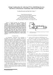
A <strong>Novel</strong> <strong>RC</strong> <strong>Model</strong> <strong>of</strong> <strong>Capacitive</strong>-<strong>Loaded</strong> <strong>Parallel</strong><br />
<strong>and</strong> <strong>Series</strong>-<strong>Parallel</strong> Re.sonant DC-DC Converters<br />
Abstract -A novel analytical methodology Is<br />
proposed<strong>and</strong>applled to Investigate the steady state<br />
processes In voltage-red parallel <strong>and</strong> serles-parallel<br />
resonant DC-DC converters wIth capacitive output<br />
filter. In this methodology the rectlrler, output<br />
capacitor <strong>and</strong> load are replaced by an equivalent<br />
circuit which Includes a capacitor <strong>and</strong> resistor<br />
connected In parallel. Excellent agreement was<br />
obtained ,,'hen comparing numerlc'al values<br />
calculated by the proposed model to cycle-by-cycle<br />
SPICE simulation <strong>and</strong> to the numerical results or<br />
earllerstudles.<br />
IN1RODUcnON<br />
Gregory Ivensky, Arkadiy Kats <strong>and</strong> Sam Ben- Yaakov<br />
Exact analysis <strong>of</strong> parallel <strong>and</strong> series-parallel DC-DC<br />
resonant conveners with capacitive output filter [I, 2, 3] is<br />
rather complex due to the fact that the equations include<br />
unknown time instances at which the output rectifier begins<br />
<strong>and</strong> ceases to conduct. The simplified analysis proposed by<br />
Steigerwald [4] is based on the method <strong>of</strong> the first harmonic.<br />
This approach is applicable to parallel <strong>and</strong> series-parallel<br />
converters with an LC output filter, but does not cover the<br />
case <strong>of</strong> a capacitor filter, in which the input current <strong>of</strong> the<br />
rectifier flows only a part <strong>of</strong> the switching period.<br />
The objectives <strong>of</strong> the present study were as follows:<br />
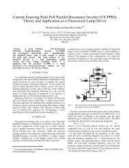
I. To develop a simple analytical method for the analysis<br />
<strong>of</strong> parallel <strong>and</strong> series-parallel converters with capacitive<br />
output filter (Fig. I);<br />
2. To obtain easy-to-use formulas <strong>and</strong> to apply them to<br />
develop design procedure for this class <strong>of</strong> converters.<br />
II. MAIN EQUA 11ONS DESCRIBING STEADY -STATE<br />
PROCESSES<br />
The analysis was carried out under the following basic<br />
assumptions:<br />
I. The converter's elements (switches, transformer .<br />
inductor, capacitors) are ideal.<br />
.Corresponding author<br />
Power Electronics Laboratory<br />
Depanment <strong>of</strong> Electrical <strong>and</strong> Computer Engineering<br />
Ben-Gurion University <strong>of</strong> the Negev<br />
P. 0. Box 653, Beer-Sheva 84105, ISRAEL<br />
Tel: +972-7-6461561; FAX: +972-7-6472949<br />
Email: sby@bguee.bgu.ee.ac.il<br />
*<br />
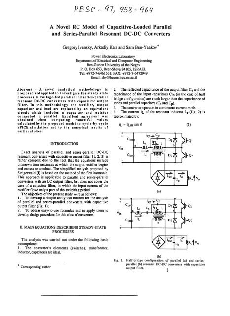
2. The reflected capacitance <strong>of</strong> the output filter Co <strong>and</strong> the<br />
capacitance <strong>of</strong> the input capacitors Cin (in the case <strong>of</strong> half<br />
bridge configuration) are much larger than the capacitance <strong>of</strong><br />
series <strong>and</strong> parallel capacitors (Cs <strong>and</strong> Cp).<br />
3. The converter operates in continuous current mode.<br />
4. The current iL <strong>of</strong> the resonant inductor Lr (Fig. 2) is<br />
approximated by:<br />
iL = ILm sin ~ (I)<br />
(a)<br />
(b)<br />
Fig. 1. Half-bridge configuration <strong>of</strong> parallel (a) <strong>and</strong> seriesparallel<br />
(b) resonant DC-DC converters with capacitive<br />
output filter.
2<br />
where ILm is the peak value <strong>and</strong> ~ = 27tft is nohnalized time<br />
in radians with zero value at ~o when the rectifier ceases to<br />
conduct, f is the switching frequency <strong>and</strong> t is time.<br />
The inductor current iL flows through the capacitor Cp<br />
during the non conducting interval <strong>of</strong> the rectifier ~o-~ I <strong>and</strong><br />
through the primary <strong>of</strong> the transformer T during the<br />
conducting interval <strong>of</strong> the rectifier ~1-~2. The rectifier's<br />
conduction angle ~-~I is defined as e (Fig. 2).<br />
The voltage across the capacitor Cp can be derived by<br />
applying the following initial conditions: at ~O = O when the<br />
output rectifier ceases to conduct vCp=- Voln. At ~ I =7t-e.<br />
when the output rectifier begins to conduct again. vCp =<br />
Vo/n. where Vo is the output voltage <strong>and</strong> n is the<br />
transformer's turns ratio (secondary to primary). Applying (1)<br />
along with the above boundary conditions we get:<br />
2VoroCQ<br />
ILm = n(l+cose)<br />
where (I) = 27tf.<br />
The peak inductor voltage is found to be:<br />
VLm = ILm (l)Lr =<br />
n (I +cos 9) -(4) (l)p<br />
2Vo ( (I) ) 2<br />
where<br />
I<br />
(I) p = -r;-;:;- ( 5)<br />
"'I LrCp<br />
The peak voltage across the series capacitor Cs (in series-<br />
(3)<br />
The OU1pU1 curren1 <strong>of</strong> the Conver1er 10 js equal 10 1he<br />
average rectifier's curren1 Irec av :<br />
7t<br />
10 = lrec av = 1- JILmsjn~d~ l ILmSjn2(~ 2) (8)<br />
7tn e 7tn<br />
7t-<br />
or applying (3):<br />
10 = Irec ay = ~ V oroCptan2( - 2e)<br />
On the other h<strong>and</strong>:<br />
7tn<br />
(9)<br />
~<br />
10 = Irec ay = Ro (10)<br />
where Ro is the load resistance.<br />
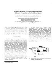
From (9) <strong>and</strong> (10) we fmd the rectifier's conduction angle:<br />
where<br />
2 ~ ~ n<br />
e = 2 tan- 1- -\' ~2tan-l 2 ~ ~= 2 roCpRO (11)<br />
parallel converter) is: Relationship (11) is depicted in Fig. 3.<br />
Now we find the first harmonics voltage <strong>and</strong> phase angle at<br />
ILm 2Vo~<br />
VCsm =roc;= n(l+cose) Cs (6)<br />
The rectifier's peak current Irec pk at \'> 1 (Fig. 2)<br />
corresponds to the reflected current <strong>of</strong> capacitor Cp just prior<br />
to the transition:<br />
the transfonner's primary (Fig. 4). The primary transfonner<br />
voltage vrl is the voltage vCp across the capacitor Cp.
3<br />
[e,deg]<br />
120-<br />
100.<br />
80-<br />
60<br />
40.<br />
20.<br />
0-<br />
-<br />
1 10 100 1000<br />
[(J)~Ro/n2]<br />
Fig. 3. Rectifier conduction angle e as a function on the load<br />
coefficient CpRoln2.<br />
,<br />
Applying (2) <strong>and</strong> the condition that vCp is equal to Voln<br />
during the conduction interval <strong>of</strong> the rectifier, we find the<br />
peak value <strong>of</strong> the first harmonics <strong>of</strong> the primary transfomler<br />
voltage:<br />
VT(l)m = VCp(l)m<br />
V<br />
= ~ kv (13)<br />
where kv is the voltage wavefoml coefficient:<br />
arxl<br />
(14)<br />
(15)<br />
2<br />
bv(l) = ; (l-cose) (16)<br />
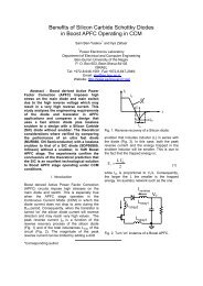
The relationship kv as a function <strong>of</strong> e is depicted in Fig. 5<br />
(solid curve). This can be approximated by:<br />
kv = I + 0.27 Sin(~) (17)<br />
(Fig. 5, dashed curve).<br />
The phase angle <strong>of</strong> the first harmonics component <strong>of</strong> the<br />
transfonner's voltage (referred to the instant ~o. Fig. 4) will<br />
be:<br />
Note that ;v(I)
4<br />
1.3<br />
[kv]<br />
[1(31. deg ]<br />
l30<br />
1.2 20<br />
f'j<br />
~l7'r1 "<br />
1.1 10<br />
1.0 -0<br />
4:1<br />
90 135 19o<br />
[ 8. deg ]<br />
Fig. 5. The voltage waveform coefficient ky <strong>and</strong> phase angle ~<br />
versus the rectifier's conduction angle 9; solid curves<br />
obtained by Fourier analysis. dashed' curves -by<br />
approximate eqs. (17) & (21).<br />
or applying (10), (13) <strong>and</strong> (23)<br />
"'2n<br />
ITI rms = 10<br />
k R (27)<br />
v cos..<br />
The secondary transformer rms current will thus be:<br />
I -.!I1-rm.:i -T --V'2<br />
T2 rms -n -'0 kv cos~<br />
(28)<br />
Applying the equivalent resistance Re <strong>and</strong> the equivalent<br />
capacitance Ce. the parallel <strong>and</strong> senes-parallel converter with<br />
the capacitive output filter can be represented by the<br />
equivalent circuits <strong>of</strong> Fig. 7a <strong>and</strong> 7b respectively. vab is the<br />
voltage between the points a <strong>and</strong> b <strong>of</strong> the original converters<br />
(Fig. 1). This voltage has a rectangular waveform with an<br />
amplitude <strong>of</strong>:tgVin. where Vin is the converter input voltage<br />
<strong>and</strong> 9 is topology constant
~<br />
5<br />
or applying (13), (29) <strong>and</strong> (30)<br />
V *-i~<br />
o -7t ky (37)<br />
Now we define the input phase angle q>(l). i.e. the angle<br />
between the voltage vab <strong>and</strong> the first hannonics <strong>of</strong> the<br />
inductor Lr current iL(l) (Fig. 7).<br />
In the parnllel converter (Figs. la <strong>and</strong> 7a)<br />
tanq>(l)= ( -(I)<br />
) 2 1 2]<br />
C R [1+«(1)CpRe+tanlpl) -<br />
(l)p (I) p e<br />
[(1)CpRe + tanlpl] (38)<br />
where Re is equivalent load resistance (eq. (23)) <strong>and</strong> ~ is the<br />
phase angle between the flfSt harmonics <strong>of</strong> the primary<br />
transformer voltage <strong>and</strong> current (Fig. 4, eq. (21)).<br />
In the series-parallel converter (Figs. Ib <strong>and</strong> 7b)<br />
1 ~ { ( ro ) 2 2<br />
tan
6<br />
The equations derived above were applied to elucidate the<br />
output characteristics <strong>of</strong> the converters (Figs. 8 & 9, solid<br />
curves). These characteristics are in excellent agreement with<br />
simulation results obtained by our group (Figs. 8 & 9,<br />
crosses <strong>and</strong> circles). They also agree very well with the<br />
results <strong>of</strong> complex analysis <strong>of</strong> Johnson <strong>and</strong> Erickson [2] <strong>and</strong><br />
Bhat [3]. The output to input voltage ratio <strong>of</strong> the parallel<br />
converter calculated by (17), (21), (32) <strong>and</strong> (37) agree with the<br />
results <strong>of</strong> Steigerwald [I] to within 10.6% (see Appendix).<br />
Note that the determination <strong>of</strong> output characteristics by the<br />
proposed method is much simpler than by more exact<br />
analyses [1-3]. This benefit is most important for parameter<br />
optimization for which the numerical data given in previous<br />
studies [1-3] may not suffice. For example, in [3] the data for<br />
series-parallel converter is given only for the case Cs=Cp.<br />
IV .CURRENT SOU<strong>RC</strong>E AND VOLTAGE SOU<strong>RC</strong>E<br />
CONDmONS<br />
The slope <strong>of</strong> the converter output characteristics (Figs. 8 &<br />
9) is a function <strong>of</strong> the frequency ratio ro/rop <strong>and</strong> ro/ros. As<br />
can be seen, both converters can operate as a
7<br />
v. DESIGN PROCEDURE (parallel converter) dependence between the peak <strong>of</strong> the inductor current ILm <strong>and</strong><br />
The following parameters are assumed to be given: output<br />
<strong>and</strong> input voltages (Vo <strong>and</strong> Vin min + Vin max), load<br />
resistance (Ro min + Ro max), nominal switching frequency<br />
f .<br />
The design begins from the case Ro min, Vin min.<br />
1. Set the values <strong>of</strong> the angles