Current-Sourcing Push-Pull Parallel-Resonance Inverter (CS-PPRI ...
Current-Sourcing Push-Pull Parallel-Resonance Inverter (CS-PPRI ...
Current-Sourcing Push-Pull Parallel-Resonance Inverter (CS-PPRI ...

You also want an ePaper? Increase the reach of your titles
YUMPU automatically turns print PDFs into web optimized ePapers that Google loves.
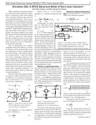
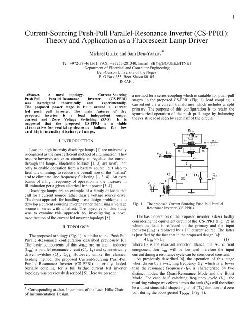
1<strong>Current</strong>-<strong>Sourcing</strong> <strong>Push</strong>-<strong>Pull</strong> <strong>Parallel</strong>-<strong>Resonance</strong> <strong>Inverter</strong> (<strong>CS</strong>-<strong>PPRI</strong>):Theory and Application as a Fluorescent Lamp DriverMichael Gulko and Sam Ben-Yaakov *Tel: +972-57-461561; FAX: +97257-281340; Email: SBY@BGUEE.BITNETDepartment of Electrical and Computer EngineeringBen-Gurion University of the NegevP. O Box 653, Beer-Sheva 80105ISRAELAbstract. A novel topology, <strong>Current</strong>-<strong>Sourcing</strong><strong>Push</strong>-<strong>Pull</strong> <strong>Parallel</strong>-<strong>Resonance</strong> <strong>Inverter</strong> (<strong>CS</strong>-<strong>PPRI</strong>)was investigated theoretically and experimentally.The proposed power stage is built around a currentfed push pull inverter. The main features of theproposed inverter is a load independent outputcurrent and Zero Voltage Switching (ZVS). It issuggested that the proposed <strong>CS</strong>-<strong>PPRI</strong> is a viablealternative for realizing electronic ballasts for lowand high intensity discharge lamps.I. INTRODUCTIONLow and high intensity discharge lamps [1] are universallyrecognized as the most efficient method of illumination. Theyrequire however, an extra circuitry to regulate the currentthrough the lamps. Electronic ballasts [1, 2] are useful notonly to enable operation from a battery source, but also tofacilitate dimming, to reduce the overall size of the "ballast"and to eliminate line frequency flickering [1, 3, 4]. An extrabonus of a high frequency of operation is the increase inillumination per a given electrical input power [3, 4].Discharge lamps are an example of a family of loads thatcall for a current source rather than a voltage source drive.The direct approach for handling these design problems is todevelop a current sourcing inverter rather than using a voltagesource in series with a ballast. The objective of this studywas to examine this approach by investigating a novelmodification of the current fed inverter topology [5].II. TOPOLOGYThe proposed topology (Fig. 1) is similar to the <strong>Push</strong>-<strong>Pull</strong><strong>Parallel</strong>-<strong>Resonance</strong> configuration described previously [6].The basic components of this stage are an input inductor(Lin), a parallel resonance circuit (Cr, Lr) and symmetricallydriven switches (Q1, Q2). However, unlike the classicalloading method, the proposed <strong>Current</strong>-<strong>Sourcing</strong> <strong>Push</strong>-<strong>Pull</strong><strong>Parallel</strong>-<strong>Resonance</strong> <strong>Inverter</strong> (<strong>CS</strong>-<strong>PPRI</strong>) is serially loaded.Serially coupling for a full bridge current fed invertertopology was previously described [5]. Here we present* Corresponding author. Incumbent of the Luck-Hille Chairof Instrumentation Design.a method for a series coupling which is suitable for push-pullstages. In the proposed <strong>CS</strong>-<strong>PPRI</strong> (Fig. 1), load coupling iscarried out via a current transformer which includes a splitprimary. The purpose of this configuration is to retain thesymmetrical operation of the push pull stage by balancingthe resistive load seen by each half of the circuit.VTf sin load2nn = 22 n 1T 12n1V inL inL rV rn1C rQ 1 D1 D 2 Q 2tR loadFig. 1. The proposed <strong>Current</strong> <strong>Sourcing</strong> <strong>Push</strong>-<strong>Pull</strong> <strong>Parallel</strong><strong>Resonance</strong> <strong>Inverter</strong> (<strong>CS</strong>-<strong>PPRI</strong>).The basic operation of the proposed inverter is described byconsidering the equivalent circuit of the <strong>CS</strong>-<strong>PPRI</strong> (Fig. 2) inwhich the load is reflected to the primary and the inputinductor (Lin) is replaced by a DC current source. The latteris justified by the fact that in the proposed design [4]:4 Lin >> Lr (1)where Lr is the resonant inductor. Hence, the AC currentcomponent thru Lin will be low and therefore the inputcurrent during a resonance cycle can be considered constant.As previously described [6], the operation of this stagewhen driven by a switching frequency (fs) which is a lowerthan the resonance frequency (fr), is characterized by twodistinct modes: the Quasi-<strong>Resonance</strong> Mode and the BoostMode. For each half switching frequency cycle (fs), theresulting voltage waveform across the tank (Vr) will thereforebe a quasi-sinusoidal shaped signal of (Tλ) duration and zerovolt during the boost period Tboost (Fig. 3).
2In response to the voltage across the parallel resonancenetwork, the resonant inductor current (iL) and therefore thecurrent through the load, will be continuous and smooth(Fig. 3). Since the transitions from one mode to the other iscarried out when the voltage across the tank is nil, thetransistors (Q1, Q2) operate under Zero Voltage Switching(ZVS). This helps to reduce switching losses at highoperating frequency. The experimental <strong>CS</strong>-<strong>PPRI</strong> was tested ata switching frequency range of 250 to 450 kHz.VGS1Ts2V GS 2tIinTLr1 1i LR load2nTλV rTboostttCrVrD1 Q1 Q D2 2Fig. 2. Simplified equivalent circuit of the proposed <strong>CS</strong>-<strong>PPRI</strong>.III. ANALYSISSf si LI Q 2I L 2 I L3I L1I Q 2,D2ID2ttA. The Quasi Resonant state.The tank voltage (vr) for the quasi-resonant period (Tλ,Fig. 4) can be derived by solving the following set ofdifferential equations:Iin2 = i C + iL (2)vr = 1 Cr ∫ iCdt (3)Fig.3.Expected waveforms of proposed <strong>CS</strong>-<strong>PPRI</strong>. (simulatedby HSICE, MetaSoftware Co.)1ωr = ωo 1- ( )nQ =2Rloadvr = Lr di L+dtiL R loadn 2 (4) ϑλ = ωr Tλwhich were evaluated by taking into account the boundryconditions constraints:vr=0 at t=0 and when t=Tλ (Fig. 4).ϑλR⎛*⎞2n 2 ⎣ ⎢⎢⎡ ⎜4-RCos(ϑλ)-e*2 -⎟ϑ λR * x- ϑ λR * x4-Re⎜ ⎟*2 Sin(ϑλx) - e⎝ ⎠⎦ ⎥⎥⎤Sin(ϑλ)vr = R loadIinwhere:Rload - Load resistor (Fig. 1).n - Turns ratio of transformer T2 (Fig. 1).Iin - Input current (Fig. 2).1ωo =Lr CrLrCr2Q4-R *2 Cos(ϑλx) + 1 (5)R * = 1 - Normalized load resistance.Qx = tTλAt steady state conditions, the average voltage (per cycle)across Lin is zero:2
3Tsϑλ2πVin - 2 vrTs 0∫ 2 dt = 0 (6) 1.141.12Applying the fact that during the Tboost period{Tλ < t < T s2 } (Fig. 4) v r = 0:1Vin =ϑλ fsπ 4-R *2 fo ∫ vr dx (7)0where:fo = ω o2πIntegrating (7), assuming that the SC-<strong>PPRI</strong> is lossless andequating input to output power, we obtain:I * load =2R * ⎣ ⎢⎢⎡4⎛ ⎞⎝4-R *2 ⎠ϑ λ Sin(ϑλ)+2Cos(ϑλ ) -2π Sin( ϑλ)4-R *2(8)where:I *nload =LrIload (r.m.s)- Normalized load current.Vin CrUtilizing the fact that the resonant inductor current (iL) issymmetrical (Fig. 3) and that it decays expotentialy duringthe boost period (Fig. 3), from (2) and (3),we find:iL= I in2⎡⎢⎢⎣fofs = 21- R* 4-R *2e2⎛1π R * ⎣ ⎢⎢⎢⎡2 ln ⎝ ⎜⎜⎛⎜⎜⎝e1.11.081.061.041.02[ ]R*=0.3R* = 0.25R*=0.2R*=0.15R * =0.111.1 1.3 1.5 1.6 1.8 2f[ o ]fsFig. 4. The normalized quasi-resonant period ( ϑ λπ = 2f rTλ) as afunction of the normalized switching frequency (fo/fs)with the normalized load (R * ) as a parameter.ϑλR *4-R *2 + e-foϑλR * ⎞fs⎟4-R *2 ⎟⎠Applying now (9), the fact that the boundry conditions as:iL=IL1 at t=0 (x=0) and iL=IL2 when t= Tλ (x=1) (Fig. 3)and the expotential behavior of the inductor current (iL), thefrequency ratio (fo/fs) is expressed as:ϑλR⎛*⎞⎤4-R⎥*2⎥⎝ ⎜⎜⎛ ⎜4-RCos(ϑλ)- e*2⎟⎛Cos(ϑλx) -⎜ ⎟R* Sin(ϑλx)⎞+ R* Cos(ϑλx)+ Sin(ϑλx)Sin(ϑλ) ⎜⎟⎝ ⎠⎠ ⎟⎟⎞⎝4-R *2 ⎠ 4-R *2 ⎦- ϑ λR * x(9)ϑλR *- ⎞- (2-R*2 )Sin(ϑλ)+R * 4-R *2 ⎝ ⎜⎜⎛ 4-RCos(ϑλ)-e*2⎠ ⎟⎟⎞ϑλR * -(2-R *2 )Sin(ϑλ)-R * 4-R *2 ⎝ ⎜⎜⎛ 4-RCos(ϑλ)-e*2 ⎠ ⎟⎟⎞⎟⎟⎠ϑλR *⎦ ⎥⎥⎥⎤⎦ ⎥⎥⎤124-R *2 (10)
4The last expression can be used to explore the dependenceof the quasi-resonant period (Tλ) on the switching frequency(fs) and load (Rload) (Fig. 4). It is evident that under theoperating conditions discussed here, the quasi-resonant periodis longer than half the period of the natural resonant frequency(fo).B. Voltage Stress.Assuming that the voltage waveform vr (Fig. 3) could beapproximated by a sinusoidal wavefom [6], and apllying (7),we find the maximun tank voltage (Vrm ) which is thevoltage stress of the transistors (VQm) and the diodes (VDm):VQm = VDm = Vrm = V inπ 2 4-R *22ϑλfofs(11)C. <strong>Current</strong> stress.The maximum normalized transistor current (I * Qm ) wasfound to be:I * Qm = IQm ω oLrVin = I * 2[ ]I * Qm109876543R * =0.3loadR * ⎝ ⎜ ⎛R*=0.2Fig. 6.I Qr.m.s * = IQr.m.s ω oLrVin[ IDm* ]6543R*=0.1R * =0.2R * =0.321 1.2 1.4 1.6 1.8 2[fo]fs(14)Normalized diode current (I * Dm ) as a function of thenormalized switching frequency (fo/fs) with thenormalized load (R * ) as a parameter.ϑλR *- ⎞⎟4 Sin(ϑλ)⎣ ⎢⎢⎡ (2-R *2 )Sin(ϑλ)+R * 4-R *2 ⎝ ⎜⎜⎛ 4-RCos(ϑλ)-e*2⎠ ⎟⎟⎞⎦ ⎥⎥⎤ ⎠12 + 1R*=0.11 1.2 1.4 1.6 1.8 2[fo]fs(12)Fig. 5. Normalized transistor current (I * Qm ) as a function ofthe normalized switching frequency (fo/fs) with thenormalized load (R * ) as a parameter.The maximum normalized diode current (I * Dm ) was derivedas:I * Dm = IDm ω oLrVin = I* Qm - I * loadR 2 * (13)The transistors' normalized r.m.s. current I * Qr.m.s wasevaluated and is shown in Fig. 8 where:[ I Qr.m.s* ]54321R * =0.3R*=0.2R*=0.101 1.2 1.4 1.6 1.8 2f[ o]fsFig. 7. Normalized transistor current (I * Qr.m.s) as a function ofthe normalized switching frequency (fo/fs) with thenormalized load (R * ) as a parameter.IV. EXPERIMENTAL RESULTSThe design parameters of the experimental <strong>CS</strong>-<strong>PPRI</strong> wereas follows:Vin=24V; Lin= 70 µH; Cr=8.24 nF; n=4; fo=487.9 kHz;Lr=12.9 µH (including 1.6 µH of leakage inductor of thetransformer T2)
5The waveform of the experimental circuit (Fig. 8) werefound to be smooth and indicative of ZVS (Fig. 3). Theparasitic oscillation of the current through the switch ispartially due to a layout modification required to facilitatecurrent measurements ( an extra loop at the drain of one ofthe transistors). It should be pointed out though, that a slightparasitic oscillation does not interfere with the inherent ZVSof the proposed <strong>CS</strong>-<strong>PPRI</strong>. The smooth operation of the <strong>CS</strong>-<strong>PPRI</strong> dispose of the need to use snubbers or clamps.The output current for various load resistances (Fig. 9)were found to be in good agreement with the analyticalexpected values (8). The somewhat larger discrepancy at highfrequency ratios (fo/fs) is due to conductive losses whichincrease as the boost period is becoming longer. Sinceparasitic losses were ignored in the present theoreticalanalysis, one would expect an inconsistency between theanalytical and experimental results when the losses are high.The theoretical and experimental results clearly point outto the fact that the proposed <strong>CS</strong>-<strong>PPRI</strong> is operating as acurrent source (Fig. 10) and that the magnitude of the outputcurrent is controlled by the driving switching frequency (fs)(Fig. 10).The overall efficiency of the experimental <strong>CS</strong>-<strong>PPRI</strong> wasfound to be around 85% for a power level of 80 Watt.V DSFig. 8. Measured waveforms of experimental <strong>CS</strong>-<strong>PPRI</strong>.Verticalscales 50V/div, 2A/div in (a) and 0.6 A/div in (b).Horizontal scales: 500 nS/div.[ I load* ]Theoretical6ExperimentalFig. 9.543210.12.01.51.31.10.15 0.2 0.25 0.3[ R * ]The relationship between the normalized output currentI * load (equation 8) and the normalized load resistanceR * (equation 10) as a function of the frequency ratio(fo/fs).I load*TheoreticalExperimental 0.15R *0.2[ ]430.3f of sI Q21.1 1.3 1.5 1.7 1.9fo[ ]fsI D(a)Fig. 10. The relationship between the normalized outputcurrent I * load (equation 8) and the frequency ratio(fo/fs) as a function the normalized load resistance R *(equation 10 ).V. APPLICATION AS A FLUORESCENT LAMPDRIVERV The current sourcing nature of the proposed <strong>CS</strong>-<strong>PPRI</strong>DS makes it a viable alternative for fluorescent lamp driver. Theproposed modification for a battery operated fluorescent lampdriver is shown in Fig. 11. The main difference of this driveras compared to the one shown in Fig. 1, is the inclusion ofi load an extra capacitor (Cig) at the output side. The purpose ofthis capacitor is to provide initial filament heating path andhigh voltage during the lamp starting period [1]. The value ofthe extra capacitor (Cig, Fig. 11) can be calculated by solvingthe set of non-linear equations for no load condition given in[7].(b)As previously documented [1, 3], fluorescent lamps exhibita resistive nature at high frequencies. This can be clearly seenby examining the experimental lamp voltage and current
6depicted in Fig. 12. It is thus evident that a first orderapproximation of a fluorescent lamp, when driven by a highfrequency source, is a pure resistor. The present study revealsthat this average resistance can be desribed by a simple modelwhich is readily interpreted is physical terms.R s = Tan(β) = V pk.1 - Vpk.2Ipk.2 - Ipk.1(17)Vmax = RsIpk.1 + Vpk.1 (18)[V] v lampT 2C igi lampV lampn 21 V pkV max2V pkα 1p.1βp. 2Fig. 11. Output section of the <strong>CS</strong>-<strong>PPRI</strong> (Fig. 1) when used as abattery operated fluorescent lamp driver.v lampfo increasefsi lampFig. 12. Measured V-I characteristic of the experimentalfluorescent lamp (General Electric type F40D/2 ) as afunction the frequency ratio fo/fs (fo/fs range: 1.1-1.5). Vertical scale: 50 V/div. Horizontal scale: 0.2A/div. Nominal switching frequency 300 kHz.Fig. 13.α 2I pk 1I pk 2i lamp [ A]The proposed model (16) of the V-I characteristic of afluorescent lamp, when driven by a high frequencysinusoidal current source. See text for details.Excellent agreement was found between measured data andR eq estimation by (16) (Fig. 14)R Ω eq[ ]280260240220200TheoreticalExperimentalThe proposed model is based on our observation (Fig. 12)1800.35 0.4 0.45I lamp r.m.s [ 0.5 A]0.55that the V-I characteristic of a fluorescent lamp when drivenby a sinusoidal current is characterized by the followingrelationship: Fig. 14. The relationship between the (dynamic) equivalentor:Ipk(Req + Rs) = Vmax (14)2 Ir.m.s(Req + Rs) = Vmax (15)where Req is the (dynamic) equivalent resistance of the lamp,Ipk is the peak current thru the lamp, Vmax is a constant ofthe lamp (akin to the breakdown voltage) and Rs is a seriesresistance. Equation (14) can be written as:Req =Vmax- Rs (16)2 Ir.m.swhere Vmax and Rs are constants of the lamp. Theexperimental parameters Vmax and Rs can be evaluated byfitting a linear curve to the top of the family curves shown inFig. 12. The line can be defined by two peak points(Vpk.1,Ipk.1), (Vpk.2,Vpk.2) (Fig. 13) to yield:resistance of the lamp (Req) and the lamp current(Ilamp (r.m.s)). The parametrs (16) of the experimentalfluorescent lamp (General Electric type F40D/2(40W)): Rs = 58.66Ω, Vmax = 121.5V.A simple interpretation to the experimantally derivedequation (16) is that the familiar low frequency V-I curve ofthe fluorescent lamp [1] represents steady state relationshipbetween the voltage across the lamp and the space chargealong it. At high enough frequency, the space charge densitydoes not decay appreciably within one cycle. Consequently athigh frequencies, the lamp represents a pure resistor whosevalue is a function of the average space charge density. Thevalue of this resistor is thus inversly proportional to thecurrent thru the lamp (16) and is influenced by the fact thatthe steady state voltage across the lamp drops as the currentthrough it increases [1].
7A. Design guidelines.The following procedure is suggested for the practicaldesign of the <strong>CS</strong>-<strong>PPRI</strong> driver for a fluorescent lamp of agiven input voltage (Vin), current (Ilamp (r.m.s) ) and power(Plamp):1. Select the switching frequency (fs) according to thetransistors and magnetic material available.2. Choose (R * ) to be in the range 0.1 to 0.2.VLinmax = V rm2 - V inILin(r.m.s) = I in(dc)These constraints normally call for an air gappedconstruction.15. The resonant capacitor (Cr) must be capable ofsustaining the expected maximum voltage (VCrmax =Vrm) and should have a low ESR.3. Select the ratio (fo/fs) to be in the range 1.1 to 1.5. VI. CONCLUSIONS4. Calculate the apparent load resistor (Rload):Rload =Plampη I 2 lamp(r.m.s)where η - the efficiency of the <strong>CS</strong>-<strong>PPRI</strong> (0.8-0.85).5. Calculate the natural resonant frequency (fo) from theratio (fo/fs).The results of the present study suggest that the <strong>CS</strong>-<strong>PPRI</strong>is a viable alternative for the realization of high frequencycurrent sources. The inherent ZVS characteristic of theproposed topology permits efficient operation at highfrequency, possibly to 1MHz, with commercially availableelectronic devices and magnetic materials. The proposed <strong>CS</strong>-<strong>PPRI</strong> is particularly useful as a driver for discharge lampwhich need to be fed by a current source. The advantage ofthis approach over previously described topologies is that iteliminates the need for an extra (inductive or capacitive)ballast. That is, there is no need to generate a much highervoltage and then to limit the current by a series impedance. Inthe proposed <strong>CS</strong>-<strong>PPRI</strong> the current is a function of thefrequency ratio (fo/fs), a feature that can be used to realize afluorescent lamp dimmer. The proposed model for theresistance of a fluorescent lamp can be useful in the design ofelectronic ballasts for these non linear devices.6. Select I * load from Fig. 10 for the chosen R * , (fo/fs).7. Calculate (Lr):I *Lr = ⎝⎛load Vin⎠ ⎞ 2 R *Ilamp(r.m.s) Rlampωowhere ωo = 2πfoI * 8. Calculate (n): n =load VinIlamp(r.m.s) ω οLrREFERENCES19. Calculate (Cr): Cr =Lr ωο 2 [1] W. Elenbaas, Ed., Fluorescent Lamps, Macmillan,10. Estimate the current stress of the transistors (IQm)and anti-parallel diodes (IDm) from (12), (13) andFigs. 5 and Fig. 6.London, 1971.11. Calculate the voltage stress of the transistors (VQm)and anti-parallel diode (VDm) from equation (11).12. The design of (Lr) is based on the inductance (Lr),maximum voltage (Vrm ), r.m.s. current (ILr(r.m.s )and switching frequency (fs):[2] J. Spangler, B. Hussain, A. K. Behera, "ElectronicFluorescent Ballast using a Power Factor CorrectionTechniques for Loads Greater Than 300 Watts," APEC-91, pp.393-399, March, 1991.[3] E. E. Hammer, "High Frequency Characteristics ofFluorescent Lamp up to 500 kHz," Journal of theIlluminating Engineering Society, pp.52-61, Winter,1987.ILr(r.m.s) = ( Ilamp(r.m.s) n )+ ( 0.5Iin)2[4] W. R. Alling, "Important Design Parameters for Solid-State Ballasts," IEEE Transactions on IndustryApplications, Vol. 25, No. 2, pp. 203-207,13. Similarily, transformer (T2) design is based on theMarch/April, 1989.D. V. Divan, "Designmaximum transformer voltage (VTrmax) and current(ITr(r.m.s) ): [5] Considerations for Very HighFrequency Resonant Mode DC/DC Converters," IEEETransactions on Power Electronics, Vol. Pe-2, No.1,pp. 45-54, January, 1987.VTrmax = V inI* Qm - 0.5I * loadR 2 * R lampn 2 [6] G. Ivensky, A. Abramovitz, M. Gulko and S. Ben-Yaakov, "A Resonant DC-DC Transformer,"IEEEITr(r.m.s) = I Lr(r.m.s)Transactions on Aerospace Electronic Systems (inpress).14. Choose (Lin) such that 4 Lin >> Lr. Calculate the [7] G. Ivensky, M. Gulko and S. Ben-Yaakov, "<strong>Current</strong>maximuminductor voltage Fed Multi-Resonant DC-DC Converter,"APEC-93 (this(VLinmax) and theinductor currentproceedings).(ILin(r.m.s) ):ωoLr ( )