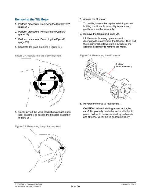
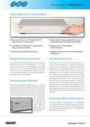
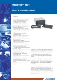
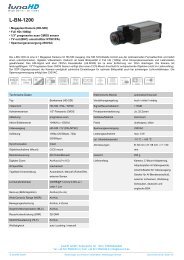
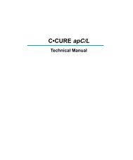
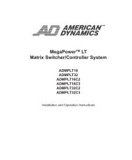
Removing the Tilt Motor1. Perform procedure "Removing the Slot Covers"(page21).2. Perform procedure "Removing the <strong>Camera</strong>"(page 22).3. Perform procedure "Detaching the Eyeball"(page 22).4. Separate the yoke brackets (Figure 27).6. Access the tilt motor.To do this, loosen the captive retaining screwholding the tilt cable assembly in place andgently remove the assembly.7. Remove the tilt motor (Figure 29).Lift the motor housing up as shown todisengage the motor from the tilt gear. Then pullthe motor bracket towards the outside of thecable/tilt assembly to remove the motor.Figure 27. Separating the yoke bracketsFigure 29. Removing the tilt motorTilt Motor(Lift up, then out.)8. Reverse the steps to reassemble.5. Gently pry off the yoke bracket covering the pangear assembly to access the tilt cable assembly(Figure 28).CAUTION: When installing a new motor, becareful to properly mesh the motor with the tiltgears! Failure to do so can destroy both motorand tilt gear. Verify the tilt gear turns freely.Figure 28. Removing the yoke bracketsSPEEDDOME ULTRA 8 CAMERA DOMEINSTALLATION AND SERVICE GUIDE 24 of 308200-0600-03, REV. B
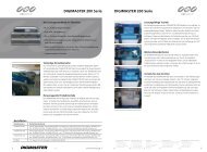
Parts List for AuthorizedUsersThe following parts can be ordered by authorizedusers only. To become authorized, contact yoursales representative. Parts in the tables below areshown in Figure 30.Parts listsBase Assembly with I/O BoardKey Description Part Number1 Mounting Base 0500-7257-02/032 I/O Board, Indoor 0312-3006-013 Dust Cover 3100-0066-014 Video XCVR BNC ADACTP01BNCHousing AssemblyKey Description Part Number5 Screws, M3x10 PHP5801-1061-120(Qty. 3†)6 Cap 0505-1224-01/027 CPU PC Board 0312-2104-018 Screw, M3x6, PHP (Qty. 2†) 5801-1041-1209 Standoff, M3x16 LG SS (Qty. 5899-0055-033†)10 Power Supply PC Board 0312-2122-0111 Pan Motor 3501-0017-0112 Screw, M3x6, PHP 5801-1041-12013 Optical Sensor 6003-0228-0114 Slip Ring Assy. 2100-0005-0215 Standoff, M3x16 LG SS (Qty. 5899-0055-033†)16 Housing 0500-7255-02/0317 Bearing Assy., Pan Gear 2510-0040-0118 Trim Ring 0505-1281-01/02Eyeball AssemblyKey Description Part Number19 Cable Assy., Tilt 0650-1680-0120 Tilt Motor 3501-0018-0121 Yoke, <strong>Camera</strong> 0500-7258-0122 Slot Cover (No Lens)* 0500-8037-01/-0223 <strong>Camera</strong>/Lens PC Board 0312-0953-0124 Bearing Assy., Lens2510-0038-01Carriage25 Yoke Bracket (Qty. 2†) 0500-8038-01/-0226 <strong>Camera</strong>, Color, 22x, NTSC 2003-0037-4127 <strong>Camera</strong>, Color, 22x, PAL 2003-0037-4228 <strong>Camera</strong>, Color, 35x, 2003-0054-01Day/Night, NTSC29 <strong>Camera</strong>, Color, 35x, 2003-0054-02Day/Night, PAL30 Screw, 1/4-20 x ½2804-7106-07(Qty. 2)31 Washer, Locking2847-0101-10(Qty. 2)32 Washer, Flat (Qty. 2) 2848-8100-0833 Screw, M2x3 (Qty. 4†) 5801-0011-12034 Screw, M2x3 (Qty. 2†) 5801-0011-12035 Tripod Mount 0500-6712-0136 <strong>Camera</strong> Support 0500-9680-0137 Slot Cover with Lens* 0404-0353-01/-02* Items 22 and 37 are supplied with the final assembly,not the eyeball assembly.† Item shipped in quantities of one. Order the quantityrequired.SPEEDDOME ULTRA 8 CAMERA DOMEINSTALLATION AND SERVICE GUIDE 25 of 308200-0600-03, REV. B