SpeedDome Ultra 8 Camera Dome Install/Service ... - IP CCTV GmbH
SpeedDome Ultra 8 Camera Dome Install/Service ... - IP CCTV GmbH
SpeedDome Ultra 8 Camera Dome Install/Service ... - IP CCTV GmbH
- No tags were found...

Create successful ePaper yourself
Turn your PDF publications into a flip-book with our unique Google optimized e-Paper software.
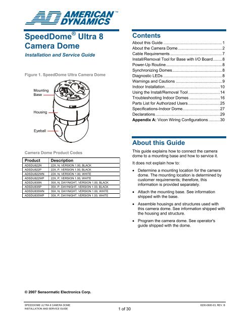
<strong>Speed<strong>Dome</strong></strong> ® <strong>Ultra</strong> 8<strong>Camera</strong> <strong>Dome</strong><strong>Install</strong>ation and <strong>Service</strong> GuideFigure 1. <strong>Speed<strong>Dome</strong></strong> <strong>Ultra</strong> <strong>Camera</strong> <strong>Dome</strong>MountingBaseHousingContentsAbout this Guide ....................................................1About the <strong>Camera</strong> <strong>Dome</strong> .......................................2Cable Requirements ..............................................7<strong>Install</strong>/Removal Tool for Base with I/O Board........8Power-Up Routine..................................................8Synchronizing <strong>Dome</strong>s............................................8Diagnostic LEDs ....................................................8Warnings and Cautions .........................................9Indoor <strong>Install</strong>ation.................................................10Using the <strong>Install</strong>/Removal Tool ............................14Troubleshooting Indoor <strong>Dome</strong>s ...........................16Parts List for Authorized Users ............................25Specifications-Indoor <strong>Dome</strong>.................................27Declarations .........................................................29Appendix A: Vicon Wiring Configurations ..........30Eyeball<strong>Camera</strong> <strong>Dome</strong> Product CodesProduct DescriptionADSDU822N 22X, N, VERSION 1.00, BLACKADSDU822P 22X, P, VERSION 1.00, BLACKADSDU822WN 22X, N, VERSION 1.00, WHITEADSDU822WP 22X, P, VERSION 1.00, WHITEADSDU835N 35X, N, DAY/NIGHT, VERSION 1.00, BLACKADSDU835P 35X, P, DAY/NIGHT, VERSION 1.00, BLACKADSDU835WN 35X, N, DAY/NIGHT, VERSION 1.00, WHITEADSDU835WP 35X, P, DAY/NIGHT, VERSION 1.00, WHITEAbout this GuideThis guide explains how to connect the cameradome to a mounting base and how to service it.It does not explain how to:• Determine a mounting location for the cameradome. The mounting location is determined bycustomer requirements; therefore, thisinformation is provided separately.• Attach the mounting base. See informationshipped with the base.• Assemble housings and structures used withthis camera dome. See information shipped withthe housing and structure.• Program the camera dome. See operator'sguide shipped with the dome.© 2007 Sensormatic Electronics Corp.SPEEDDOME ULTRA 8 CAMERA DOMEINSTALLATION AND SERVICE GUIDE 1 of 308200-0600-03, REV. B
Indoor Ceiling/Wall Mounting(Optional)The camera dome attaches to one of the followingoptional indoor mounting structures (Figure 4).Sheet Rock, Concrete, Plaster or Wood CeilingsRHIUTHRHIUHCRHIUFBRHIUPNDT†Structural I-BeamsRHIUIB /RHIUIBM†Top hat housing with trim ring.This housing attaches to a ceiling or tomost indoor mounting structures. A trimring and optional magnetic bubbleprovide concealment. Optional bubbles:RUCLR (clear), RUSLV (silver), RUSMK(smoked), or RUGLD (gold).<strong>Dome</strong> base included.Hard ceiling bracket.Enables top hat housing to be recessedin ceiling (requires top hat RHIUTH).Can be installed from below ceiling.Fixed bracket.Enables top hat housing to be recessedin ceiling (requires top hat RHIUTH).Requires access from above ceiling.Pendant mount.Suspends dome from a hard ceiling with3.2cm (1 1/4in) NPT pipe fittings.I-beam mount only.Enables dome suspension from anI-beam. RHIUIBM version has all relatedaccessories to suspend from I-beam,except 3.2cm (1 1/4in) NPT pipe.Tile CeilingsRHIUFBRHIUABRHIU2X2M*RHIU2X2P*Fixed bracket.Enables top hat housing to be recessedin a 2x2 tile (requires top hat RHIUTH).Adjustable bracket.Enables top hat housing to be recessedin a 2x4 tile (requires top hat RHIUTH).2 X 2 metal tile mount.Enables top hat housing to be recessedin 2x2 openings (includes top hathousing).2 X 2 metal tile pendant mount.Enables dome to be suspended from 2x2openings. Requires 3.2cm (1 1/4in) NPTpipe (allow 3m (10ft) max. length).Accepts the following housings:RHIOTH, <strong>Dome</strong> base.* Option in white, but can be painted to match decor.† Top hat housing/dome assembly also mounts to structure.Wall MountingRHIUCM*RHIULWM*†Wall mount with corner feature.Enables dome to attach to a flat wall,inside corner, or outside corner.Long 60cm (24in) wall mount.Positions dome away from wall to enableit to see over furniture, shelving, anddisplays. This mounting structureattaches to the flat wall, inside corner, oroutside corner.* Option in white, but can be painted to match decor.† Top hat housing/dome assembly also mounts to structure.Electrical Box in CeilingRHIU3X3RHIU4X43 X 3 mounting plate.Attaches dome to a standard3.5 x 3.5 duplex electrical box.CAUTION: Do not use the sameelectrical box used for line voltagemains.4 X 4 mounting plate.Attaches dome to a standard 4 x 4duplex electrical box.CAUTION: Do not use the sameelectrical box used for line voltagemains.* Option in white, but can be painted to match decor.† Top hat housing/dome assembly also mounts to structure.SPEEDDOME ULTRA 8 CAMERA DOMEINSTALLATION AND SERVICE GUIDE 3 of 308200-0600-03, REV. B
Figure 4. Indoor mounting structures (optional)RHIUFB, RHIUAB RHIUHC RHIU2X2RHIU2X2P (with options)ADSDUPIHCADSDUPIHSADSDUPIVRCADSDUPIVRSRHIUIBM (with options)RHIUTHRHIUTHADSDUPIHCADSDUPIHSADSDUPIVRCADSDUPIVRSRD500AVandal-ResistantBubbleRHIUTHVandal-ResistantBubbleRD500ARHIUWMRHIUPNDTRHIUCMRHIUTRRHIU3X3RHIU4X4RUCLRRUSLVRUSMKRUGLDRHIULWM (with option)RHIUTHSPEEDDOME ULTRA 8 CAMERA DOMEINSTALLATION AND SERVICE GUIDE 4 of 308200-0600-03, REV. B
Outdoor Mounting (Optional)Note: This document does not include installationand service instructions for the AD outdoorhousing. These instructions are supplied with thehousing.The camera dome attaches to outdoor walls andceilings using an AD outdoor housing (Figure 5)and an ROENDC end cap connected to one of thefollowing optional mounting structures (Figure 7).• RHOTR Over Roof Mount• RHOTRF Over Roof Floor Mount• RHOPN Pendant Mount• RHOWPA Pole Mount• RHOSW/RHOLW Wall Mount• RHOWCA Corner Bracket.<strong>Speed<strong>Dome</strong></strong> Housing AdapterBracket (Optional)An RHSDA adapter bracket (Figure 6) enables thedome to fit into <strong>Speed<strong>Dome</strong></strong> indoor housings(RD500A). Locking pins in the bracket enable thedome to swing out for servicing or removal.Figure 6. RHSDA adapter bracket(used with the RD500A housing)The outdoor housing contains a pre-installedmounting base, a cooling fan for hot weather, aheater for cool weather and to prevent icing, andsurge protection circuitry.An environmental PC board is used to pre-wirecables. A round spring-finger connector on theboard makes electrical contact with the housingand eyeball assembly as it connects to the base.Note: Do not use the I/O board (designed forindoor use) in place of the environmental board.Figure 5. AD outdoor housing (optional)SPEEDDOME ULTRA 8 CAMERA DOMEINSTALLATION AND SERVICE GUIDE 5 of 308200-0600-03, REV. B
Figure 7. Outdoor mounting structures(optional).Note: Housing is shown for reference only.RHOTR over roof mount comes with the ROENDCend cap (shown with RHOTRF bracket)ROENDC end capRHOWPA pole mount comes with the ROENDCend capRHOSW/RHOLW wall mount comes with theROENDC end capRHOPN pendant mountRHOSWRHOLWRHOWCA corner bracket only (shown with RHOLWmount)SPEEDDOME ULTRA 8 CAMERA DOMEINSTALLATION AND SERVICE GUIDE 6 of 308200-0600-03, REV. B
Cable RequirementsData CableThe table below shows requirements forSensorNet, RS-422, and Manchester networks. Formore information about communication protocolsand cable networks, see Communication Protocolsand Cable Networks, 8000-2573-19.Data cable requirementsCable type 1unshielded,twistedpair*SensorNet RS-422 Manchester2shielded,twisted pair*1shieldedtwistedpair**Wire gauge 22 AWG 22 AWG 18 AWGConnectionMax.devices onlineNonpolarizedPolarized32 10 3Polarized* Power, data, and video cables can be orderedseparately or within a composite cable that can beordered in various lengths. Plenum-rated cables mustbe used in indoor ceilings used for environmental airreturn (called "other air space" in the National ElectricalCode). Order parts through your distribution network.Note: If you order cable from an outside source, wirecolors may be different.** Belden 88760 (plenum), or Belden 8760 cable (nonplenum)cable is recommended. Plenum-rated cablesmust be used in indoor ceilings used for environmentalair return (called "other air space" in the NationalElectrical Code). Order cable directly from Belden bycalling 1-800-235-3361.Power CableFor the camera dome to operate properly, linevoltage must not go below the worst-case low linevoltage shown in the following table. Make cablelengths as short as possible to minimize the affectsof low line voltages.As shown in the table, the maximum cable lengthdepends on the Class 2 LPS (low voltage) acsource (such as a J-box) and the worst-case lowline voltage. These lengths are for Sensormaticcomposite cables, which use 18 AWG ac powerwires.Note: Typically, distances are used that providea 15% margin between nominal and low lineconditions. For example, if the nominal voltage is120Vac, restrict cable length to that associatedwith 100Vac (0.85 x 120).Worst-case ac line voltagesIndoor <strong>Dome</strong> Worst-Case MetersAC Power Source Low Line V (Feet)28 VA 117 180 (600)Transformer 100 130 (430)5604-0006-01 90 80 (270)50 VA 117 180 (600)Transformer 100 150 (500)5604-0044-01 90 90 (300)Outdoor 117 210 (700)1-position SensorNet 100 130 (430)RJ1SNUD 90 100 (325)Outdoor (PAL) 240 210 (700)1-position SensorNet 200 130 (430)RJ1SNUD-1 180 100 (325)117 300 (1000)6-position SensorNet 100 230 (750)Indoor J-Box 90 160 (530)RJ6SN 240 300 (1000)200 230 (750)180 160 (530)10-Position RS-422 117 275 (900)Indoor 120V/60Hz J-Box 100 200 (650)RJ860AP 90 130 (430)10-Position RS-422 240 275 (900)Indoor 240V/60Hz J-Box 200 200 (650)RJ860AP1 180 130 (430)Universal Transformer 117 200 (650)0300-0914-01 100 130 (430)90 90 (300)Universal Transformer 240 200 (650)0300-0914-03 200 130 (430)180 90 (300)SPEEDDOME ULTRA 8 CAMERA DOMEINSTALLATION AND SERVICE GUIDE 7 of 308200-0600-03, REV. B
<strong>Install</strong>/Removal Tool for Basewith I/O BoardThe install/removal tool (Figure 8) enables you toconnect or disconnect the housing and eyeballassembly from the mounting base, and toattach/detach skirts and bubbles from a top-hathousing, without the need for a ladder. The toolattaches to a telescopic pole (purchasedseparately). See page 14.CAUTION: Do not use this tool to connect thedome to the base without I/O board.Figure 8. RHIRT indoor install/removal toolRHIRT Removal ToolTelescopic PolePower-Up RoutineAfter power is connected to the dome, the domeperforms the following homing routine.After a few seconds, the camera lens tilts up intothe housing and eyeball assembly and then tiltsdown until it looks at the floor. While doing this, theeyeball pans fast in one direction to find theapproximate home position, then pans slowly tofind the exact home position.Note: If this is the first time power was connectedto the dome, the dome will home to thesecoordinates: 90° tilt, 0° pan. Otherwise, the domewill home to the position it was in when lastpowered down.Once the lens is in its home position, the controllercan be used to call up the camera and control it.Synchronizing <strong>Dome</strong>sTo prevent picture rolling when switching fromcamera to camera, all domes can be synchronizedto a 50Hz or 60Hz ac source.A V-phase adjustment at the control consoleenables the dome to sync to any line phase.Diagnostic LEDsLEDs on the underside of the mounting baseenable you to check for power and data.If an RS-422 network is used, other LEDs on theboard indicate that wiring is correct, reversed,open, or grounded.SPEEDDOME ULTRA 8 CAMERA DOMEINSTALLATION AND SERVICE GUIDE 8 of 308200-0600-03, REV. B
Warnings and CautionsPlease review the following warnings and cautionsbefore you begin installation or service.WARNINGS! WARNING!ALWAYS USE:• Proper safety equipment for the location andtype of installation.• Proper lift equipment to reach the installation.• Safety features of the lift equipment.BE SURE:• Electrical power is not connected to the domewhen connecting wires. <strong>Dome</strong> will move whenpower is applied.• Electrical power is not connected to nearbyfixtures that you might touch during installation.!!WARNING! DO NOT install this cameradome where highly combustible orexplosive products are stored or used.WARNING! This dome runs on 24Vac.DO NOT connect line voltage to thisdome.North America power requirements: InNorth America, this device is intended tobe supplied from a Class 2 powersupply. For outdoor installations, useClass 3 wiring techniques, liquid-tightconduit, or liquid-tight pipe.This installation should be made by aqualified service person and shouldconform to all local codes.! WARNING!EU power requirements: This product runs on24Vac. In the EU, it is intended to be powered froma Limited Power Source. A limited power source isa certified source of SELV, and if inherently limited,with 8 amps maximum output current, and amaximum of 100VA available; or if not inherentlylimited, fused with a maximum value of 3.3 Amps,meeting section 2.11 of IEC950, and a maximum of250VA available.The power supply can be obtained throughSensormatic or through another source where theprovider can furnish the verification. This isrequired to assure electrical safety in the product.Stromanforderungen in der EU: Dieses Produkt wirdmit 24 V Wechselstrom betrieben. In der EU ist es fürden Betrieb durch eine begrenzte Stromquellevorgesehen. Eine begrenzte Stromquelle ist einezertifizierte SELV-Quelle (Schutzkleinspannung), beiinhärenter Begrenzung mit einem maximalenAusgangsstrom von 8 A und 100 VA maximalerVerfügbarkeit, bei nicht inhärenter Begrenzung mit einermaximalen Sicherung von 3,3 A gemäß Abschnitt 2.11der IEC950 und 250 VA maximaler Verfügbarkeit. DasNetzteil kann über Sensormatic oder eine andere Quellebezogen werden, wobei der Anbieter den Nachweis derKonformität bereitstellen sollte. Dies ist zurGewährleistung der elektrischen Sicherheit desProduktes erforderlich.CAUTION• Cables:- Do not run data and power cables adjacent to orin the same conduit as line voltage mains power.- SensorNet 485 networks require 22 AWGunshielded cable. Do not exceed 32 devices percable run.- RS-422 networks require 22 AWG shielded cable.Do not exceed 10 devices per cable run.- Manchester networks require 18 AWG shieldedcable. Do not exceed 3 devices per cable run.• I/O PC board:− Use a jeweler's 2.5mm (0.1in) slotted screwdriverto tighten connector screws. Do not over tightenthese screws.− Always terminate I/O board jumper E1 if the domeconnects at the end of a cable run.− Keep the dust cover to protect contacts should theenvironmental PC board need to be removedfrom the housing.• When connecting the housing and eyeballassembly to an outdoor housing remove bothslot covers to keep the camera fromoverheating.• If disassembling the dome:− <strong>Dome</strong> contains electrostatic-sensitive devices!Use a ground strap when handling PC boards.− Once disassembled, parts of housing and eyeballassembly are fragile and may break. Use extremecare!SPEEDDOME ULTRA 8 CAMERA DOMEINSTALLATION AND SERVICE GUIDE 9 of 308200-0600-03, REV. B
4. Connect twisted pair wires, if used, to connectorTB5.Pin1 VideoDesignation2 Video GroundFigure 9. Electrical connections6. Connect the alarm input cable, if used, to theTB3 connector.Pin Color Designation1 — Alarm 1 input (3.5mA sink)2 — Alarm 2 input (3.5mA sink)3 — Alarm 3 input (3.5mA sink)4 — Alarm 4 input (3.5mA sink)5 — Ground6 — Ground7. Connect power to the TB4 connector.Pin Color Designation1 Black 24Vac2 Red Ground3 White 24VacVideoTwistedPairRS-422 Data,SensorNet Data,Manchester Data8. Reattach the I/O board.9. Connect power to the base.10. Check LEDs on the I/O board to verify powerand data are reaching the dome (Figure 10).VideoBNCAlarmInputsAlarmOutputs5. Connect the alarm output cable, if used, to theTB2 connector.Pin Color Designation1 — 12Vdc (100mA max.)2 — 12Vdc (100mA max.)3 — Output 1 (40mA sync. max.)4 — Output 2 (40mA sync. max.)5 — Output 3 (40mA sync. max.)6 — GroundPowerTerminationJumpera. The green ac power LED (CR9) glowssteadily when ac power is applied.b. For Manchester or SensorNet: The yellowcomm. LED (CR11) glows steadily(Manchester) or blinks (SensorNet). If thisLED is off, then probably one or bothcommunication wires are open or both areshorted together.For RS-422: Press and hold data test switchSW1 and observe nearby red (CR12) andgreen (CR13) LEDs; they indicate thefollowing:Constant green,Blinking redConstant green,Red offConstant red,Blinking greenBlinking red,Green offBoth LEDs offRS-422 line correctly wired.RS-422 "Data In –" shortedto ac ground."Data In +/ –" wiresreversed."Data In +" shorted to acground."Data In +/ –" wires shortedor open.SPEEDDOME ULTRA 8 CAMERA DOMEINSTALLATION AND SERVICE GUIDE 11 of 308200-0600-03, REV. B
Figure 10. Test switch/LEDs on I/O boardRed(CR12)Green(CR13)SW1Yellow(CR11)11. Set the dome address (Figure 11).Figure 11. Setting address switchesSW3MSBSW2Green(CR9)SW1LSB0 9 0 9 0 9Use the following addresses for the protocolsshown:PROTOCOL SW3 SW2 SW1AD Manchester,0 x xRange: 001—064PELCO "P," 4800 baud0 x xRS-422, Range: 001–099Sensormatic, 4800 baud0 x xRS-422, Range: 001–063, 065–099Sensormatic, RS-422 Address 64 is 0 6 4used for global broadcastsSensorNet,0 x xRange: 001–099VICON, 4800 baud RS-422, Range: 0 x x001–099SensorNet,1 x xRange: 100–254 2 x xAddress 255 is used for global2 5 5broadcastsDept. of Transportation (NTC<strong>IP</strong>), 3 x x4800 baud RS-422, Range: 301–399Dept. of Transportation (NTC<strong>IP</strong>), 4 x x9600 baud RS-422, Range: 401–499Dept. of Transportation (NTC<strong>IP</strong>), 5 x x19.2K baud RS-422, Range: 501–599PELCO "P," 2400 baud6 x xRS-422, Range: 601–699PELCO "P," 9600 baud7 x xRS-422, Range: 701–799Reset camera block from 38.4K to 8 3 04800 baud (<strong>Speed<strong>Dome</strong></strong> <strong>Ultra</strong> VIIWITH EIS 0100+ feature only).PANASONIC UTC 8 9 0Tyco UTC 8 9 1PELCO UTC (Origins, Standard, & 8 9 3Extended)RS-422, LED diagnostic mode for 9 0 0dome wiring installations without theI/O BoardManufacturing Use,Range: 901-9999 x xSPEEDDOME ULTRA 8 CAMERA DOMEINSTALLATION AND SERVICE GUIDE 12 of 308200-0600-03, REV. B
12. Connect the housing and eyeball assembly tothe base (Figure 12) by aligning the cap andbase tabs, and then turning the housingclockwise until you hear a click.Note: The base has a florescent arrow and dot.Once the housing is secured, only the florescentdot will be seen.Note: Tabs on the base and cap have smallholes that align once the base and cap arelocked. If required, insert the security pinsupplied (part number 2869-0037-01) throughthe holes.CAUTION: Use of the security pin prevents theuse of the install/removal tool.Figure 12. Connecting housing and eyeballassembly to mounting baseAlign tabs onCap and Base.Turn clockwiseto latch13. Wait a few seconds for dome to begin itshoming routine. This routine indicates that theaddress was placed into the dome memory andthat the dome is ready for programming.SPEEDDOME ULTRA 8 CAMERA DOMEINSTALLATION AND SERVICE GUIDE 13 of 308200-0600-03, REV. B
Using the <strong>Install</strong>/RemovalToolCAUTION: Do not use this tool to connect thedome to the standard base (without I/O board)CAUTION: Use of the security pin prevents the useof the install/removal tool.The RHIRT install/removal tool is used only whenthe dome is connected to a base having an I/Oboard. The tool eliminates the need for a ladderduring routine service. It can be used to:• Detach the skirt or bubble from the housing, ifused. The skirt or bubble remains attached tothe housing during service.• Connect/Disconnect the dome from the basewith I/O board.• Reattach the skirt or bubble.Telescopic Pole Required to Use ToolThe tool attaches to a telescopic pole used to cleanswimming pools. The pole should be approximately 1.7m(5.5ft) telescoping to 4.7m (15.5ft) long. It should have a29.7mm (1.17in) inside diameter to accept the 28.6mm(1.125in) outside diameter stem of the tool.ProcedureReferring to Figure 13, maneuver the stem of thetool into the top of the pole until it snaps into place.TO CONNECT DOME:1. Insert the dome "eyeball down" into the tool'sreceptacle. Fins on the dome mate with slots inthe tool. Use the fins to properly align thedimple at top of the dome with the label on thetool.2. Align the label on the tool with the logo on theI/O board in the base. Push the dome up intoplace.3. Turn the dome clockwise until it clicks.4. If power is applied, the dome should begin its"homing" routine.5. Lower the pole.TO DISCONNECT DOME:1. Raise the pole and insert the dome "eyeballdown" into the tool's receptacle.2. Fins on the dome mate with the slots in the tool.3. Turn the dome counterclockwise until it unlocks.4. Lower the pole "vertically" to prevent thecamera dome from falling out.CAUTION: Turning the pole horizontally as it islowered can cause the camera dome to fall outof tool and possibly break on the floor.5. Remove the dome for service.TO ATTACH SKIRT OR BUBBLE:Use the tool to push up on the bubble to secure itin place. Magnets secure the bubble. Lower thepole.TO DETACH SKIRT OR BUBBLE:Lifting the pole up at an angle, use one of thehooks on the tool to catch one of the notches at theside of the dome and pull down. The T-lanyard willprevent the skirt or bubble from falling.SPEEDDOME ULTRA 8 CAMERA DOMEINSTALLATION AND SERVICE GUIDE 14 of 308200-0600-03, REV. B
Figure 13. How to use the install/removal toolSkirt or Bubble Attachment/DetachmentA B CSnap toolinto poleCatch notchand pull downAttachmentDetachment<strong>Dome</strong> Connection (Reverse the steps to disconnect)Line upLine upBDTurn untilyou feel aclickCESPEEDDOME ULTRA 8 CAMERA DOMEINSTALLATION AND SERVICE GUIDE 15 of 308200-0600-03, REV. B
Troubleshooting Indoor<strong>Dome</strong>sCAUTION: This troubleshooting section is forindoor camera domes only! To troubleshootoutdoor domes, see the installation and serviceguide shipped with the outdoor housing.This chapter contains information on:• Routine troubleshooting• Detailed troubleshooting• Disassembling the dome.IMPORTANT!1. Try routine troubleshooting first! Use thisprocedure to isolate the problem withoutdisassembling the housing and eyeballassembly (the I/O board is field repairable).CAUTION: DO NOT troubleshoot if the domefunctions but does not pan or tilt (see step 2).2. If you cannot isolate the problem or the domefunctions but does not pan or tilt, contact yoursales representative for repair instructions.3. If you have no choice but to repair the housingand eyeball assembly. Follow the detailedtroubleshooting procedure, but use extremecare.CAUTION: Once disassembled, parts of thehousing and eyeball assembly are "extremelyfragile" and may break. Proceed using extremecare!Items You Will NeedYou should have on hand the following items:• Phillips screwdriver• Small slotted screwdriver• 2.5mm (0.1in) slotted screwdriver (for wireconnections). Wider blade widths can damageconnectors.• Socket wrench with 127mm (5in) extension and5.5mm, 6mm, 8mm, and 10mm sockets• 14-18 AWG and 20-22 AWG wire strippers• <strong>Install</strong>/Removal tool to connect/disconnectdome to indoor bases with I/O boards, and toattach/detach skirts and bubbles—without aladder.Routine TroubleshootingUse this procedure if:• <strong>Dome</strong> does not respond to commands• <strong>Dome</strong> does not produce video• Quality of the video is poor• <strong>Dome</strong> has no lens control.CAUTION:• DO NOT use this procedure if the domefunctions but does not pan or tilt (see step 2 onpage 16).• Use a ground strap when handling the I/Oboard. When shipping the base and I/O boardassembly, place the dust cover over the springfinger connector to protect it.• DO NOT over tighten connector screws on theI/O board; they are delicate. Use a 2.5mm(0.1in) slotted screwdriver. Wider blade widthscan damage connectors.ProcedureFollow steps until the problem is corrected.1. Check video on monitor (a, b, or c).a. No video? Go to step 2.b. Contrast or color off?YES Contact your sales representative forrepair instructions.NO Go to step 2.c. Video rolls when switching betweenmonitors?YES Use the video controller or switcher tosynchronize video vertical sync phasesof all domes to ac line. For specificinstructions, see the installation andservice guide for the controller orswitcher.NO Go to step 2.2. Check ac power and video connections atJ-box. Are 24Vac and/or video signal absent?YES Correct problem at J-box.NO Go to step 3.SPEEDDOME ULTRA 8 CAMERA DOMEINSTALLATION AND SERVICE GUIDE 16 of 308200-0600-03, REV. B
3. Detach the dome from its base. Are the addressswitches set correctly?YES If dome still doesn't respond, contact yoursales representative for repairinstructions. If you must repair the dome,see Detailed Troubleshooting onpage 18.NO Set correct address and reattach housingand eyeball assembly.Figure 14. I/O board connector and jumperlocations4. Isolate the problem to the housing/eyeballassembly or base by attaching dome to anotherbase. Does dome display video or respond tocommands?YES Problem is likely cable connections or theI/O board, if used. Go to step 5.NO Contact your sales representative forrepair instructionsTwistedPairRS-422 Data,SensorNet Data,Manchester Data5. Verify the video cable is securely connected tocoax of I/O board (Figure 14). Is the cabledisconnected?YES Connect cable.NO Go to step 6.6. Observe the green power LED CR9 on the I/Oboard (Figure 15). Is the LED off or not onsteady?YES Verify the 24Vac cable is properlyattached. If so, replace the I/O board orcontact your sales representative forrepair instructions.NO Go to step 7.P7 Connector (AC in)Pin Color Designation1 Black 24Vac2 Red Ground3 White 24Vac7. Observe the yellow comm. LED CR11 on theI/O board (Figure 15). Is the LED on or flashing?YES Go to step 8.NO Verify the cable is properly attached byreferring to table in step 9, page 18. If so,replace the I/O board or contact yoursales representative for repairinstructions.VideoAlarmsPowerP1 connector (Manchester data)Pin Color Designation1-4 Not used.5 Black Manchester (+)6 White Manchester (–)P1 connector (RS-422 data)Pin Color Designation1 Orange RS-422 Data In High (+)2 Green RS-422 Data In Low (–)3 Yellow RS-422 Data Out High (+)4 Brown RS-422 Data Out Low (–)5-6 — Not used.P1 connector (SensorNet 485 data)Pin Color Designation1-4 — Not used.5 Orange SensorNet 4856 Yellow SensorNet 485TerminationJumperSPEEDDOME ULTRA 8 CAMERA DOMEINSTALLATION AND SERVICE GUIDE 17 of 308200-0600-03, REV. B
8. If using RS-422 network and an I/O board isused, check comm. line connections bypressing and holding data test switch SW1(Figure 15) and observing nearby red (CR12)and green (CR13) LEDs. These LEDs indicatethe following:Constant green,Blinking redConstant green,Red offComm. line correctly wired."Data In -" shorted to ground.9. Check the spring finger connector on the I/Oboard by connecting a known good dome to thebase to verify contact between the springfingers and the CPU board (under cap). Doesdome produce video and respond tocommands?YES Spring fingers may not have seatedproperly. Reconnect housing and eyeballassembly.NOReplace I/O board.Constant red,Blinking greenBlinking red,Green offBoth LEDs off"Data In +/ -" wires reversed."Data In +" shorted to ground."Data In +/ -" wires shorted oropen.If routine troubleshooting did not solve theproblem, the manufacturer stronglyrecommends that you contact your salesrepresentative for repair instructions.If you must perform detailed troubleshooting,use extreme care when disassembling parts!See Detailed Troubleshooting, next.Figure 15. I/O board test switch and LEDlocationsYellow(CR11)Detailed TroubleshootingUse this procedure to determine if the problem is asimple cable connection or a major component.To perform this procedure, you must open thehousing and eyeball assembly. Refer to"Disassembling the <strong>Dome</strong>" on page 19.Red(CR12)Green(CR13)SW1Green(CR9)CAUTION:• DO NOT use this procedure if the domefunctions but does not pan or tilt (see step 2 onpage 16).• If routine troubleshooting did not solve theproblem, the manufacturer stronglyrecommends that you contact your salesrepresentative for repair instructions. If you mustperform detailed troubleshooting, use extremecare when disassembling parts!• When shipping a base and I/O board assembly,use a dust cover to protect the spring fingers.• Connector screws on the I/O board are delicate.DO NOT over tighten them! Use a 2.5mm(0.1in) slotted screwdriver. Wider blade widthscan damage connectors.• The dome contains electrostatic-sensitive PCboards. Use a ground strap when handlingthese boards.SPEEDDOME ULTRA 8 CAMERA DOMEINSTALLATION AND SERVICE GUIDE 18 of 308200-0600-03, REV. B
ProcedureChoose a, b, c, d or e to determine if the problem isa cable connection or major component.a. <strong>Dome</strong> functions but does not pan.On the power supply board, is the pan motorribbon cable attached to connector P2 and isthe metal side of its fingers towards the contactsof connector?YES Replace the power supply board. If thisdoesn't work, replace the pan motor.NO Connect the cable(s).b. <strong>Dome</strong> functions but does not tilt.On the camera/lens board, is the tilt motor cableattached to connector P3?YES Replace the camera/lens board. If thisdoesn't work, replace the tilt motor orpower supply board.NO Connect the cable(s).c. <strong>Dome</strong> pans to the home position but doesnot tilt or display video.On the power supply board, is the slip ring cableattached to connector P1?YES Replace the <strong>Camera</strong>/Lens board.NO Connect the cable.Disassembling the <strong>Dome</strong>CAUTION: Once disassembled, parts of domehousing and eyeball assembly are "extremelyfragile" and may break. Use extreme care!This section explains how to remove the followingparts from the camera dome.• CPU board, page 20• Power supply, page 20• Pan motor, page 21• Slot covers, page 21• <strong>Camera</strong>, page 22• Eyeball, page 22• <strong>Camera</strong>/Lens board, page 23• Tilt motor, page 24.To order parts (authorized users only), seepage 25.Tools Required• Phillips screwdriver.• Small slotted screwdriver.d. <strong>Dome</strong> does not "home" or respond tocommands even when attached to anotherdome's base and its address switches areset correctly (dead dome).Is the slip ring cable attached to connector P1?YES Replace the CPU board. If this doesn'twork, replace the power supply board.NO Connect the cable(s).e. <strong>Dome</strong> functions but does not find the panhome position.On the bottom of the power supply board, checkthat the optical sensor is functioning andplugged into connector P3 on the power supplyboard.SPEEDDOME ULTRA 8 CAMERA DOMEINSTALLATION AND SERVICE GUIDE 19 of 308200-0600-03, REV. B
Removing the CPU BoardCAUTION: Electrostatic-sensitive device. Use aground strap when handling CPU board.Referring to Figure 16.1. Remove cap.Remove the three Phillips screws holding thecap, then "gently" lift the cap (this will unplugthe CPU board from the power supply).2. Remove CPU board.Remove the two screws holding the board in theend cap. Then push your finger through largefinger connector hole in the cap to pop out theboard.3. Reverse the steps to reassemble.Figure 16. Removing the CPU boardRemoving the P/S BoardCAUTION: Electrostatic-sensitive device. Use aground strap when handling power supply board.Referring to Figure 17.1. Remove three Phillips screws holding the cap,then "gently" lift the cap (this will unplug theCPU board from the power supply).2. On the power supply board, detach 14-pin slipring cable from connector P1 and pan motor flatflex cable from connector P2.3. Carefully lift the power supply board and tilt it tothe edge to remove the 4-pin optical sensorcable P3 on the bottom of the board.4. Remove the power supply board.5. Remove three standoffs. Then remove thepower supply board from the housing.6. Reverse the steps to reassemble.Figure 17. Removing the P/S boardP2P1P3(underside ofPC board)SPEEDDOME ULTRA 8 CAMERA DOMEINSTALLATION AND SERVICE GUIDE 20 of 308200-0600-03, REV. B
Removing the Pan MotorReferring to Figure 18.1. Perform procedure "Removing the P/S Board"(page 20).2. Remove pan motor.a. Lift the motor housing up as shown todisengage the motor from the pan gear.b. Then pull the motor bracket towards theoutside of the housing to remove it.3. Reverse the steps to reassemble.CAUTION: When putting in a new motor, becareful to properly mesh motor and pan gears!Failure to do so can destroy both motor and pangear. Verify pan gear turns freely!Removing the Slot Covers1. Gently swivel eyeball to totally expose one oftwo slot covers (Figure 19).CAUTION: Swiveling fast can damage gears.2. Insert small, thin-bladed screwdriver into spacebetween cover and eyeball.3. Gently pry off slot cover.4. Gently swivel eyeball to totally exposeremaining slot cover. With other cover removed,this cover can be easily removed.Figure 19. Removing slot coversFigure 18. Removing the pan motorb. Pull outa. Lift upSPEEDDOME ULTRA 8 CAMERA DOMEINSTALLATION AND SERVICE GUIDE 21 of 308200-0600-03, REV. B
Removing the <strong>Camera</strong>1. Perform procedure "Removing the Slot Covers"(page21).2. Remove ribbon cable from camera (Figure 20).Swivel camera yoke to expose cameraconnector. Then, using a small slottedscrewdriver, 1) gently pry camera connectorloose from camera, and 2) pull it down throughcable tie wrap.Figure 20. Removing the ribbon cable12Detaching the Eyeball1. Perform procedure "Removing the Slot Covers"(page 21).2. Perform procedure "Removing the <strong>Camera</strong>"(this page).3. Detach the eyeball from the housing (Figure22).a. Turn the yoke to access the tabs. One tab ismore accessible than the other. Use yourfinger to press this tab while using a smallslotted screwdriver to press the other tab.b. While pressing both tabs, push up on eyeballto detach it.Figure 22. Loosening the eyeball3. Remove camera (Figure 21).1) Loosen the screw holding the camera tripodmount and then 2) carefully lift the camera out.Figure 21. Removing the camera24. Detach slip ring connector (Figure 23).1Figure 23. Detaching the eyeball4. Reverse the steps to reassemble. Ensureribbon cable pins are inserted "face down".SPEEDDOME ULTRA 8 CAMERA DOMEINSTALLATION AND SERVICE GUIDE 22 of 308200-0600-03, REV. B
Removing the <strong>Camera</strong>/Lens Board1. Perform procedure "Removing the Slot Covers"(page 21).2. Perform procedure "Removing the <strong>Camera</strong>"(page 22).3. Perform procedure "Detaching the Eyeball"(page 22).4. Separate the yoke brackets (Figure 24).Figure 24. Separating the yoke bracketsThe following steps refer to Figure 26.6. Access camera/lens board.To do this, loosen captive retaining screwholding bearing assembly in place and removethis assembly.7. Remove cables from camera/lens board.a. Small amber ribbon cable is from tilt motor.Unplug this cable from connector J3 oncamera/lens board.b. Large gray ribbon cable is from slip ringconnector. Unplug this cable from connectorJ2 on camera/lens board.DO NOT unplug small white ribbon cable fromconnector J1.8. Push out on the three prongs to detach thecamera/lens board.9. Reverse the steps to reassemble.Figure 26. Removing the camera/lens boardProngs (3)DO NOT unplugcable from J1.5. Gently pry off the yoke bracket covering thecamera/lens board to access the bearingassembly (Figure 25).J3 (Pins on ribboncable must facecontacts onconnector.)Figure 25. Removing the yoke brackets<strong>Camera</strong>/Lens BoardBearing AssemblySPEEDDOME ULTRA 8 CAMERA DOMEINSTALLATION AND SERVICE GUIDE 23 of 308200-0600-03, REV. B
Removing the Tilt Motor1. Perform procedure "Removing the Slot Covers"(page21).2. Perform procedure "Removing the <strong>Camera</strong>"(page 22).3. Perform procedure "Detaching the Eyeball"(page 22).4. Separate the yoke brackets (Figure 27).6. Access the tilt motor.To do this, loosen the captive retaining screwholding the tilt cable assembly in place andgently remove the assembly.7. Remove the tilt motor (Figure 29).Lift the motor housing up as shown todisengage the motor from the tilt gear. Then pullthe motor bracket towards the outside of thecable/tilt assembly to remove the motor.Figure 27. Separating the yoke bracketsFigure 29. Removing the tilt motorTilt Motor(Lift up, then out.)8. Reverse the steps to reassemble.5. Gently pry off the yoke bracket covering the pangear assembly to access the tilt cable assembly(Figure 28).CAUTION: When installing a new motor, becareful to properly mesh the motor with the tiltgears! Failure to do so can destroy both motorand tilt gear. Verify the tilt gear turns freely.Figure 28. Removing the yoke bracketsSPEEDDOME ULTRA 8 CAMERA DOMEINSTALLATION AND SERVICE GUIDE 24 of 308200-0600-03, REV. B
Parts List for AuthorizedUsersThe following parts can be ordered by authorizedusers only. To become authorized, contact yoursales representative. Parts in the tables below areshown in Figure 30.Parts listsBase Assembly with I/O BoardKey Description Part Number1 Mounting Base 0500-7257-02/032 I/O Board, Indoor 0312-3006-013 Dust Cover 3100-0066-014 Video XCVR BNC ADACTP01BNCHousing AssemblyKey Description Part Number5 Screws, M3x10 PHP5801-1061-120(Qty. 3†)6 Cap 0505-1224-01/027 CPU PC Board 0312-2104-018 Screw, M3x6, PHP (Qty. 2†) 5801-1041-1209 Standoff, M3x16 LG SS (Qty. 5899-0055-033†)10 Power Supply PC Board 0312-2122-0111 Pan Motor 3501-0017-0112 Screw, M3x6, PHP 5801-1041-12013 Optical Sensor 6003-0228-0114 Slip Ring Assy. 2100-0005-0215 Standoff, M3x16 LG SS (Qty. 5899-0055-033†)16 Housing 0500-7255-02/0317 Bearing Assy., Pan Gear 2510-0040-0118 Trim Ring 0505-1281-01/02Eyeball AssemblyKey Description Part Number19 Cable Assy., Tilt 0650-1680-0120 Tilt Motor 3501-0018-0121 Yoke, <strong>Camera</strong> 0500-7258-0122 Slot Cover (No Lens)* 0500-8037-01/-0223 <strong>Camera</strong>/Lens PC Board 0312-0953-0124 Bearing Assy., Lens2510-0038-01Carriage25 Yoke Bracket (Qty. 2†) 0500-8038-01/-0226 <strong>Camera</strong>, Color, 22x, NTSC 2003-0037-4127 <strong>Camera</strong>, Color, 22x, PAL 2003-0037-4228 <strong>Camera</strong>, Color, 35x, 2003-0054-01Day/Night, NTSC29 <strong>Camera</strong>, Color, 35x, 2003-0054-02Day/Night, PAL30 Screw, 1/4-20 x ½2804-7106-07(Qty. 2)31 Washer, Locking2847-0101-10(Qty. 2)32 Washer, Flat (Qty. 2) 2848-8100-0833 Screw, M2x3 (Qty. 4†) 5801-0011-12034 Screw, M2x3 (Qty. 2†) 5801-0011-12035 Tripod Mount 0500-6712-0136 <strong>Camera</strong> Support 0500-9680-0137 Slot Cover with Lens* 0404-0353-01/-02* Items 22 and 37 are supplied with the final assembly,not the eyeball assembly.† Item shipped in quantities of one. Order the quantityrequired.SPEEDDOME ULTRA 8 CAMERA DOMEINSTALLATION AND SERVICE GUIDE 25 of 308200-0600-03, REV. B
Figure 30. Base, housing, and eyeball assembly* ADSDU8IOB/ ADSDU8IOBWBase Assemblywith I/O Board*Housing Assembly(0404-0306-01/-0254126783 910Housing and Eyeball Assy.,<strong>Speed<strong>Dome</strong></strong> <strong>Ultra</strong> 8(0101-0150-xx)1112131415161718Eyeball Assy. (0404-0079-xx)20192112-01 Color 22X NTSC camera (BLK)-02 Color 22X PAL camera (BLK)-05 Color 22X NTSC camera (WHT)-06 Color 22X PAL camera (WHT)-31 Color 35X NTSC camera (BLK)-32 Color 35X PAL camera (BLK)-35 Color 35X NTSC camera (WHT)-36 Color 35X PAL camera (WHT)3533233726-2932312425363034SPEEDDOME ULTRA 8 CAMERA DOMEINSTALLATION AND SERVICE GUIDE 26 of 308200-0600-03, REV. B
Specifications-Indoor <strong>Dome</strong>OperationalPan/Tilt:Manual pan speed .................. 0.25°-100° per second(scaled to zoom position)Manual tilt speed..................... 0.25°-100° per second(scaled to zoom position)Preset pan speed: .............360° per second maximumPreset tilt speed ................220° per second maximumPan travel..............................360° continuous rotationTilt travel ..............................................................110°Pan/Tilt accuracy.................................................±0.5°Auto synchronization:Line locked.....................Remote V-phase adjustmentInternal .....................................Built-in sync generatorUp-the-coax ............................................System syncAddress range ........................... 1-99 (RS-422/RS-485),1-64 (Manchester), 1-255 (SensorNet)AD-UTC (based on number of inputs)Preset access time .................
22X <strong>Camera</strong>Type............................Interline transfer 1/4in CCD arrayScanning area ................................3.2 (H) x 2.4 (V) mmScanning system .........................................2:1 interlaceHorizontal resolution..........................470 lines at centerVideo out .......................... 1.0 Vp-p/75 ohms compositeSignal-to-noise.......................................... 50dB (typical)Minimum illumination ..............0.3 lux (AGC On, 20 IRE)0.02 lux with ¼ sec open shutterWhite balance......... Through-the-Lens (TTL), AutomaticTracing White balance (ATW)NTSC:Pickup device.........................768 (H) x 494 (V) pixelsScanning ......................525 lines, 60 fields, 30 framesHorizontal................................................... 15.734kHzVertical .............................................................59.9HzPAL:Pickup device.........................752 (H) x 582 (V) pixelsScanning ......................625 lines, 50 fields, 25 framesHorizontal................................................... 15.625kHzVertical ................................................................50HzLens Design:Type ........................................................... AsphericalFocal length ............................................... 4 to 88mmAperture ..................f1.6 (wide angle), f3.8 (telephoto)Viewing angle (equivalent to 8mm to 80mm on ½-inchCCD array or 11mm to 110mm on 2/3-inch CCD array):4mm ..............................................47.0°(H) x 35.2°(V)88mm ................................................2.2°(H) x 1.6°(V)Total zoom..............................................................242XOptical zoom.............................................................22XDigital zoom..............................................................11XZoom pause.........................33X default; 22X selectableZoom stop................................. 44X, 66X, 88X (default),110X, 132X, 154X,198X, 220X, 242XZoom/Focus accuracy .......................................... ±0.5%35X Day/Night <strong>Camera</strong>Type ........................... Interline transfer 1/4in CCD arrayScanning area................................ 3.2 (H) x 2.4 (V) mmScanning system......................................... 2:1 interlaceHorizontal resolution ......................... 540 lines at centerVideo out...........................1.0 Vp-p/75 ohms compositeSignal-to-noise ..........................................50dB (typical)Minimum illumination............ 0.24 lux (AGC On, 20 IRE)0.028 lux with ¼ sec open shutter0.021 lux in IR mode0.00041 lux in IR mode with ½ sec open shutterWhite balance .........Through-the-Lens (TTL), AutomaticTracing White balance (ATW)NTSC:Pickup device ........................ 768 (H) x 494 (V) pixelsScanning ..................... 525 lines, 60 fields, 30 framesHorizontal ...................................................15.734kHzVertical ............................................................ 59.9HzPAL:Pickup device ........................ 752 (H) x 582 (V) pixelsScanning ..................... 625 lines, 50 fields, 25 framesHorizontal ...................................................15.625kHzVertical ............................................................... 50HzLens Design:Type ........................................................... AsphericalFocal length...........................................3.4 to 119mmAperture.................. f1.4 (wide angle), f3.4 (telephoto)Viewing angle:3.4mm .......................................... 55.8°(H) x 41.8°(V)119mm ............................................. 1.7°(H) x 1.3°(V)Total zoom ............................................................. 420XOptical zoom ............................................................ 35XDigital zoom ............................................................. 12XZoom pause ........................ 52X default; 35X selectableZoom stop ..................... 71X, 94X, 117X, 140X (default)163X, 186X, 209X, 232X, 255X,278X, 301X, 324X, 347X, 370X,393X, 420XZoom/Focus accuracy...........................................±0.5%SPEEDDOME ULTRA 8 CAMERA DOMEINSTALLATION AND SERVICE GUIDE 28 of 308200-0600-03, REV. B
Field-of-View Formulas:3.2mm* x distance from camera (m)Focal length (mm) x Digital Zoom2.4mm** x distance from camera (m)Focal length (mm) x Digital Zoom= Horizontal view (m)= Vertical view (m)* Horizontal scanning area of pickup device (mm) incamera.** Vertical scanning area of pickup device (mm) incamera.Example: Wide angle view with lens at 6mm and viewedobject at 10m.3.2mm x 10m6mm2.4mm x 10m6mmDeclarations= 5.33m Horizontal view (m)= 4.0m Vertical view (m)Regulatory ComplianceREG ID ............................................................... VP SDUEmissions ................................ 47 CFR, Part 15, Class AICES-003 Class AEN55022 Class AEN61000-3-2EN61000-3-3Immunity ........................................................ EN50130-4Safety .................................................................. UL1950CSA C22.2 No. 950EN 60950-1Other DeclarationsThank you for using American Dynamics products. Wesupport our products through an extensive and worldwidenetwork of dealers. The dealer, through whom you originallypurchased this product, is your point of contact if you have aneed for service or support. Our dealers are fully empoweredto provide the very best in customer service and support.Dealers should contact American Dynamics at(800) 507-6268 or (561) 912-6259 or on the web atwww.americandynamics.net.WARRANTY DISCLAIMER: Sensormatic ElectronicsCorporation makes no representation or warranty with respectto the contents hereof and specifically disclaims any impliedwarranties of merchantability or fitness for any particularpurpose.NOTICE: The information in this manual was current whenpublished. The manufacturer reserves the right to revise andimprove its products. All specifications are therefore subject tochange without notice.LIMITED RIGHTS NOTICE: For units of the Departmentof Defense, all documentation and manuals were developed atprivate expense and no part of it was developed usingGovernment Funds. The restrictions governing the use anddisclosure of technical data marked with this legend are setforth in the definition of “limited rights” in paragraph (a) (15)of the clause of DFARS 252.227.7013. Unpublished - rightsreserved under the Copyright Laws of the United States.TRADEMARK NOTICE: American Dynamics andSensormatic are trademarks or registered trademarks ofSensormatic Electronics Corporation. Other product namesmentioned herein may be trademarks or registered trademarksof Sensormatic or other companies.COPYRIGHT: Under copyright laws, the contents of thismanual may not be copied, photocopied, reproduced,translated or reduced to any electronic medium or machinereadableform, in whole or in part, without prior writtenconsent of Sensormatic Electronics.MDR 01/2007FCC COMPLIANCE: This equipment complies with Part 15of the FCC rules for intentional radiators and Class A digitaldevices when installed and used in accordance with theinstruction manual. Following these rules provides reasonableprotection against harmful interference from equipmentoperated in a commercial area. This equipment should not beinstalled in a residential area as it can radiate radio frequencyenergy that could interfere with radio communications, asituation the user would have to fix at their own expense.EQU<strong>IP</strong>MENT MODIFICATION CAUTION: Equipmentchanges or modifications not expressly approved bySensormatic Electronics Corporation, the party responsible forFCC compliance, could void the user's authority to operate theequipment and could create a hazardous condition.www.americandynamics.netSPEEDDOME ULTRA 8 CAMERA DOMEINSTALLATION AND SERVICE GUIDE 29 of 308200-0600-03, REV. B
Appendix A: Vicon Wiring ConfigurationsIn Vicon systems where domes support loop through, daisy chain the <strong>Speed<strong>Dome</strong></strong> <strong>Ultra</strong> 8 domes off the lastVicon dome in the communications chain.Figure 31. <strong>Speed<strong>Dome</strong></strong> <strong>Ultra</strong> 8 dome loop-through wiring from Vicon domeTo controller orother domesIn Out In OutCommand ResponseVicon dome<strong>Speed<strong>Dome</strong></strong><strong>Ultra</strong> 8 dome<strong>Speed<strong>Dome</strong></strong><strong>Ultra</strong> 8 domeIn Vicon systems where domes support RS-485 daisy chaining, daisy chain the <strong>Speed<strong>Dome</strong></strong> <strong>Ultra</strong> 8 domes offthe controller or one of the Vicon domes in the communications chain.Figure 32. <strong>Speed<strong>Dome</strong></strong> <strong>Ultra</strong> 8 dome RS-485 wiring from Vicon domeTo controller orother domes+ - + - R+ R- T+ T-R+ R- T+ T-In OutCommand ResponseVicon dome<strong>Speed<strong>Dome</strong></strong><strong>Ultra</strong> 8 dome<strong>Speed<strong>Dome</strong></strong><strong>Ultra</strong> 8 domeSPEEDDOME ULTRA 8 CAMERA DOMEINSTALLATION AND SERVICE GUIDE 30 of 308200-0600-03, REV. B