Service Manual - The Expert - Dana Holding Corporation Product ...
Service Manual - The Expert - Dana Holding Corporation Product ...
Service Manual - The Expert - Dana Holding Corporation Product ...

Create successful ePaper yourself
Turn your PDF publications into a flip-book with our unique Google optimized e-Paper software.
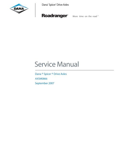
<strong>Dana</strong> ® Spicer ® Drive Axles<br />
<strong>Service</strong> <strong>Manual</strong><br />
<strong>Dana</strong> ® Spicer ® Drive Axles<br />
AXSM0866<br />
September 2007<br />
More time on the road
Axle Identification ................................................................................. 2<br />
Model Identification Numbering System ......................................... 3<br />
Gear Set Identification ......................................................................... 3<br />
Axle Lubricant Recommendations ..................................................... 4<br />
General Precautions .............................................................................. 5<br />
Axle Components .................................................................................. 6<br />
Removal ................................................................................................... 7<br />
Differential Carrier from Axle Housing<br />
Differential from Carrier<br />
Differential Disassembly ...................................................................... 8<br />
Pinion Removal ....................................................................................... 10<br />
Cleaning and Inspection ...................................................................... 11<br />
Pinion Assembly ..................................................................................... 12<br />
Differential Assembly ............................................................................ 14<br />
Pinion Position ....................................................................................... 15<br />
Pinion Setting Chart ............................................................................. 16<br />
Differential Installation......................................................................... 18<br />
Ring Gear and Pinion Tooth Contact Pattern ................................. 19<br />
Wheel Bearing Adjustment ................................................................. 20<br />
Fastener Torques and Axle Specifications........................................ 21<br />
Installation of Differential Carrier Into Axle Housing ................... 22<br />
Recommended <strong>Service</strong> Tools .............................................................. 23<br />
GENUINE SPICER SERVICE PARTS<br />
Should an axle assembly require replacement component<br />
parts, it is recommended that Spicer Heavy Axle<br />
<strong>Service</strong> Parts be used. Spicer Heavy Axle <strong>Service</strong> Parts<br />
are manufactured under the same rigid specification as<br />
are original equipment axle components. This assures<br />
the customer who uses genuine Spicer service parts,<br />
maximum reliability for a Spicer Heavy Axle assembly.<br />
<strong>The</strong>y may be obtained through your vehicle manufac-<br />
1<br />
TABLE OF CONTENTS<br />
turer. <strong>The</strong> use of non-original Spicer service parts may<br />
cause premature component failure and may void the<br />
warranty.<br />
<strong>The</strong> items included in this book are currently being<br />
offered as service parts at the time of printing. <strong>The</strong><br />
part numbers and illustrations are provided specifically<br />
for reference purposes only. <strong>The</strong>refore, Spicer reserves<br />
the right to update this manual without notice or<br />
liability.
AXLE IDENTIFICATION<br />
LAST SIX DIGITS OF<br />
VEHICLE SERIAL NUMBER<br />
(OPTIONAL)<br />
DANA PART<br />
NUMBER<br />
MODEL YEAR<br />
All axle assemblies are identified with two tags. One<br />
located on the differential carrier, and the other located<br />
on the right hand side of the axle housing. Two types of<br />
tags may be found on the axle, an aluminum tag that is<br />
riveted on the assembly or a coated mylar tag.<br />
<strong>The</strong> aluminum differential carrier tag contains the<br />
following items: serial number, according to the julian<br />
date code, the <strong>Dana</strong> part number, and ratio. <strong>The</strong> mylar<br />
differential carrier tag contains the following: <strong>Dana</strong><br />
part number, julian date code, and ratio. Optional items<br />
DANA PART<br />
NUMBER<br />
Carrier Tag<br />
LAST SIX DIGITS OF<br />
VEHICLE SERIAL NUMBER<br />
(OPTIONAL)<br />
CUSTOMER<br />
PART NUMBER<br />
(OPTIONAL)<br />
Axle Assembly Tag<br />
97 070<br />
DAY OF YEAR<br />
CUSTOMER<br />
PART NUMBER<br />
(OPTIONAL)<br />
LINE SET<br />
NUMBER<br />
(OPTIONAL)<br />
MODEL<br />
LINE SET<br />
NUMBER<br />
(OPTIONAL)<br />
JULIAN DATE<br />
CODE<br />
JULIAN DATE<br />
CODE<br />
2<br />
JULIAN JULIAN JULIAN D DDATE<br />
D TE CODE<br />
CODE<br />
070 97<br />
DAY OF YEAR MODEL YEAR<br />
Mylar Tag Aluminum Tag<br />
include customer part number, line set number, and the<br />
last six digits of the vehicle serial number.<br />
<strong>The</strong> aluminum axle assembly tag�contains the following<br />
items: serial number, according to the julian date, <strong>Dana</strong><br />
part number, and the model. <strong>The</strong> mylar axle assembly<br />
tag contains the following items: <strong>Dana</strong> part number,<br />
julian date code, axle model, and ratio. Optional items<br />
include customer part number, line set number, and the<br />
last six digits of the vehicle serial number.<br />
SERIAL NUMBER<br />
���������<br />
�����������<br />
�����������<br />
Carrier Tag<br />
SERIAL NUMBER<br />
���������<br />
����������<br />
Axle Assembly Tag<br />
DANA PART NUMBER<br />
DANA PART NUMBER<br />
������������<br />
MODEL
Family<br />
(J & W)<br />
Nominal Load<br />
Carrying Capacity<br />
(175 = 17,500 Lbs.)<br />
(190 = 19,000 Lbs.)<br />
(210 = 21,000 Lbs.)<br />
(220 = 22,000 Lbs.)<br />
(230 = 23,000 Lbs.)<br />
GEAR SET IDENTIFICATION<br />
���������������������Date gear set was made.<br />
������������������Company logo and location of<br />
manufacturing facility.<br />
����������Part number of pinion. (TYPICAL)<br />
�������������������������������Indicates the pinion<br />
has 11 teeth and the ring gear has 41 teeth which<br />
results in a 3:73:1 ratio.<br />
��������������������Spicer ring gears and pinions<br />
are manufactured as matched sets. Both ring gear and<br />
pinion are marked with a corresponding number (i.e.<br />
260), which identifies them as a matched set.<br />
A gear set that does not have the same match set<br />
numbers should not be run together. If either ring gear<br />
or pinion require replacement, a new matched set must<br />
be used.<br />
���������������Indicates backlash setting for assembly.<br />
�������������Indicator for proper pinion position shim<br />
stack up. (See�����������������Pg. 15)<br />
MODEL IDENTIFICATION NUMBERING SYS-<br />
TEM<br />
J 175 S N<br />
Gearing Type<br />
(S = Single Reduction)<br />
3<br />
41-11<br />
TOOTH<br />
COMBINATION<br />
SPICER<br />
TRADEMARK<br />
PART<br />
NUMBER<br />
Options<br />
(N = *No-SPIN ® Differential)<br />
HEAT<br />
CODE<br />
* No-SPIN ® is a registered trademark of Tractech<br />
SPICER<br />
TRADEMARK<br />
PINION<br />
ETCH<br />
MFG.<br />
DATE<br />
L10<br />
BACKLASH<br />
ETCH<br />
+15<br />
260<br />
MATCHED<br />
SET NUMBER<br />
260
AXLE LUBRICANT RECOMMENDATIONS<br />
To ensure proper lubrication and operating temperature,<br />
correct lubricants and lubricant levels must be obtained.<br />
RECOMMENDED GEAR LUBRICANTS<br />
Mineral or Synthetic based hypoid gear lubricants that<br />
meet or exceed military specification MIL-L-2105D, and<br />
API service classification GL-5, are the minimum requirements<br />
for use in Spicer Medium and Heavy Duty Drive<br />
Axles.<br />
<strong>The</strong> table below indicates which SAE viscosities are<br />
recommended for various temperature ranges the vehicle<br />
will encounter.<br />
SERVICE<br />
AMBIENT AIR TEMPERATURE<br />
Recommended lubricant change intervals are dependent<br />
on the application and operating environment. <strong>The</strong><br />
following chart should be used to establish proper<br />
change intervals.<br />
SUBMERSION OR DEEP WATER FORDING<br />
In the event the carrier housing should become<br />
submerged in water, particularly if over the vent or<br />
breather, it is recommended that the lubricant be<br />
drained and all internal parts be inspected for water<br />
damage and/or contamination. Reassemble the carrier<br />
to the housing and refill with specified gear lubricant.<br />
4<br />
������������ ��������������������������������������<br />
����������������������������������������������������������<br />
On Highway 100,000 1 Year 250,000 3 Year<br />
��Severe <strong>Service</strong><br />
and 50,000 1 Year 100,000 1 Year<br />
On-Off Highway<br />
* Severe service includes any applications operating at<br />
or near maximum GVW or GCW ratings. This<br />
includes normally wet or dusty environment, or<br />
consistent high load and low speed applications.<br />
** Includes Semi-Synthetic blends that meet<br />
MIL-L-2105D specifications.<br />
AFTER OVERHAUL OR CHANGE INTERVALS<br />
Fill the axle assembly to the bottom of housing fill hole<br />
as shown in the illustration below. It is recommended<br />
that following an overhaul, each side of the axle be<br />
jacked up separately to approximately six inches and<br />
held into position for one minute. This procedure will<br />
allow adequate lubricant to flow into the wheel<br />
ends and help eliminate the possibility of premature<br />
damage to wheel bearings and seals. Lower the vehicle<br />
to the floor and allow ten minutes for lube to return to<br />
normal level. Check and refill assembly to bottom of fill<br />
hole to replace the lubricant that was directed into the<br />
wheel ends.<br />
����� Lubricant close enough to the bottom of the fill hole to be seen or<br />
touched is not sufficient. Lubricant must be level with the fill hole.
GENERAL AXLE DESCRIPTION<br />
This manual covers maintenance and rebuild procedures<br />
for the Spicer J175-S, J190-S, J210-S, J220-S, J230-SB<br />
and W230-S rear drive axle assemblies.<br />
<strong>The</strong> Spicer Heavy Duty Single Reduction Rear Drive Axle<br />
is a full floating hypoid gear carrier assembly in one<br />
piece HSLA steel axle housing. <strong>The</strong> hypoid pinion is<br />
straddle mounted, having two tapered roller bearings<br />
ahead of the pinion teeth for forward and rear thrust,<br />
and also having a third bearing behind the pinion teeth<br />
for radial load. <strong>The</strong> differential itself uses four precision<br />
forged pinion mate gears, a forged cross, and precision<br />
forged side gears. A fresh supply of lube oil is fed to the<br />
differential assembly by our Spicer positive flow lube<br />
system. Axle shafts and drive pinion splines are of the<br />
rolled involute type.<br />
Follow the sections of this manual that cover individual<br />
service needs.<br />
SAFTEY PRECAUTIONS<br />
Proper service and repair of vehicle components is<br />
important to the safe and reliable operation of all motor<br />
vehicles. This applies particularly to driving axles such<br />
as the ones described in this manual. <strong>The</strong> procedures<br />
recommended and described in this manual are tested,<br />
and effective methods for performing service operations.<br />
Follow each procedure closely, making use of both the<br />
text and illustrations. Some of these service procedures<br />
show the use of certain tools designed specifically for<br />
the operation being performed. <strong>The</strong>y are shown as a<br />
preferred means of performing the operation. It is not<br />
practical to anticipate and advise the service trade of all<br />
possible alternative methods, and of all possible hazardous<br />
consequences that could occur.<br />
���������<br />
���������������������������������<br />
����������������������<br />
5<br />
GENERAL PRECAUTIONS<br />
Accordingly, anyone who uses a service procedure or<br />
tool different than shown must insure that their safety,<br />
and the vehicle's safety, will not be jeopardized by the<br />
service method selected.<br />
END YOKES AND FLANGES<br />
����������������� Hammering on end yokes can close in<br />
the bearing bores or misalign yoke lugs and result in<br />
early failures of journal needle bearings or other driveline<br />
components. Serious damage can also be done<br />
internally to the ring and pinion set or pinion bearings<br />
by hammering on external parts. End yokes or companion<br />
flanges should be removed or installed using the<br />
recommended methods outlined in this manual.<br />
CLEANLINESS<br />
Axle components should be steam cleaned prior to<br />
removal from the vehicle. Dirt is abrasive and will cause<br />
premature wear of otherwise serviceable parts.<br />
<strong>Service</strong> personnel should use a wash tank for thorough<br />
cleaning of parts just prior to reassembly.<br />
�����������������������������<br />
����������������������������<br />
�����������������������<br />
CAUTION<br />
�����������������������������������������<br />
��������������������������������������������������������������<br />
���������������������������������������������������<br />
�������������������<br />
������ ������������������������������������������������������<br />
�����������������������������������������������������������<br />
�����������������������������������������������������������<br />
������������������������������������������������������������������<br />
����������������������������������������������������������<br />
������������������������������������������������������������������<br />
����������������������������������
AXLE COMPONENTS<br />
NOTE: Torque specifications, shown<br />
on illustration, apply only to J Model.<br />
See Page 21 for W Model torque<br />
specifications.<br />
Pinion-Up Components<br />
Axle Shaft<br />
Fill Plug<br />
(35-45 Lb-Ft)<br />
(47-61 N-m)<br />
Temperature Sensor Plug<br />
(35-45 Lb-Ft)<br />
(47-61 N-m)<br />
6<br />
Housing<br />
Differential Bearing Cap<br />
Ring Gear Bolt Kit<br />
Adjusting Ring<br />
Differential Side Gear<br />
Differential Bearing Cup<br />
Differential Cross Shaft<br />
Differential Bearing Cone<br />
Differential Case Bolt<br />
(115-135 Lb-Ft)<br />
Differential Bearing Cap Bolt<br />
(156-183 N-m)<br />
(295-340 Lb-Ft)<br />
Differential Gear Thrust Washer<br />
(397-460 N-m)<br />
Differential Case Cap Half<br />
Differential Case Flange Half<br />
Differential Bearing Cap Washer<br />
Ring Gear Rivet<br />
(45-50 tons)<br />
(41-45 metric tonnes)<br />
Differential Pinion Mate<br />
Cotter Pin<br />
Differential Pinion MateThrust Washer<br />
Differential Case Nut<br />
Adjusting Ring Lock<br />
No-Spin ® Differential<br />
Carrier Housing<br />
Carrier Mounting Bolt<br />
(240-260 Lb-Ft)<br />
(325-352 N-m)<br />
Vent Plug<br />
Magnetic Drain Plug<br />
(35-45 Lb-Ft)<br />
(47-61 N-m)<br />
Pinion Pilot Bearing<br />
Pinion<br />
Inner Pinion Bearing Cup<br />
Ring Gear<br />
Inner Pinion Bearing Cone<br />
Pinion Position Shim(s)<br />
Pinion Bearing Spacer (Selective)<br />
Outer Pinion Bearing Cup<br />
Pinion Bearing Cage<br />
Pinion Bearing Cage Bolt<br />
(160-180 Ft-Lb)<br />
(217-244 N-m)<br />
Outer Pinion Bearing Cone<br />
Bearing Preload Spacer<br />
Pinion Oil Seal<br />
Washer<br />
End Yoke Assembly<br />
Flanged Hex Nut<br />
(900-1,200 Lb-Ft)<br />
(1,220-1,627 N-m)
DIFFERENTIAL FROM AXLE HOUSING<br />
��������������������������������<br />
�� Block wheels.<br />
�� Remove magnetic drain plug and drain lubricant<br />
�� Disconnect drive shafts at the rear U-joint.<br />
������������������������������������������������<br />
�����������������������������<br />
�� Remove axle shaft stud nuts and lock washer, or<br />
cone locks if used.<br />
�� Remove axle shafts. If a gasket is assembled between<br />
the hub and shaft, discard the old gasket and<br />
replace it with a new one at the time of assembly.<br />
��������������������������������������������������<br />
������������������������������������������������������<br />
�������������������������������������������������������<br />
������������������������������������������������������<br />
�����������������������������<br />
�� Remove axle shafts.<br />
�� Support the differential carrier assembly on a roller<br />
jack. Secure as necessary to prevent it from<br />
falling off the jack when removed from the housing.<br />
�� Loosen the carrier-to-housing mounting bolts.<br />
Remove all bolts except top two. <strong>The</strong>se two bolts<br />
will prevent the carrier assembly from falling.<br />
��������<br />
�������<br />
����<br />
��������<br />
��������<br />
�������<br />
����<br />
7<br />
DIFFERENTIAL FROM CARRIER<br />
��������<br />
REMOVAL<br />
�� Install two 1/2"-13 bolts into threaded holes provided<br />
in carrier housing flange. ��������� Be certain<br />
carrier is balanced properly on jack, and remove top<br />
two carrier mounting bolts. Remove differential<br />
carrier assembly from the axle housing.<br />
��� Mount carrier assembly in a suitable rebuild stand.<br />
(See �������������������������, pg. 23).<br />
�� Remove adjusting ring locks from bearing caps.<br />
�� Match mark one differential bearing cap and leg<br />
with center punch or chisel for reference during<br />
reassembly. �������������<br />
�� Loosen four bearing cap retainer bolts.<br />
�� Loosen adjusting rings, relieving bearing preload.<br />
�� Remove four bearing cap retainer bolts.<br />
�� Remove bearing caps.<br />
�� Remove adjusting rings.<br />
�������������������������������������<br />
�� Carefully lift the ring gear and differential subassembly<br />
out of the carrier.<br />
������������������������������������������������<br />
���������������������������������������������������������<br />
����������������������<br />
���������������������������������
Used on W Model carriers that do<br />
not have oil scoope cast integrally<br />
to the flange half of the differential<br />
case.<br />
Differential Gear Thrust Washer<br />
Differential Case Cap Half<br />
Differential Cross Shaft<br />
Differential Case Nut<br />
Differential Side Gear<br />
�� Match mark differential case halves with punch or<br />
chisel for correct alignment in reassembly. ���<br />
���������<br />
�� Remove differential case bolts and lift off differential<br />
case cap half.<br />
�� Remove differential gear thrust washer and differential<br />
side gear.<br />
�� Lift out differential cross shaft, differential pinion<br />
mates, and differential pinion mate thrust washers.<br />
�� Remove second differential side gear and differential<br />
side gear thrust washer.<br />
8<br />
DIFFERENTIAL DISASSEMBLY<br />
Ring Gear<br />
Differential Pinion Mate<br />
Differential Pinion MateThrust Washer<br />
Differential Bearing Cone<br />
Ring Gear Rivet<br />
(45-50 tons)<br />
(41-45 metric tonnes)<br />
Adjusting Ring<br />
Differential Case Bolt<br />
(115-135 Lb-Ft)<br />
(156-183 N-m)<br />
Differential Case Flange Half<br />
��������<br />
Differential Bearing Cup<br />
NOTE: Torque specifications, shown<br />
on illustration, apply only to J Model.<br />
See Page 21 for W Model torque<br />
specifications.
�� If differential bearing cones are to be replaced,<br />
remove old bearings using a suitable puller. ���<br />
���������<br />
��������<br />
�����������������������������������������������<br />
����������������������������<br />
If any gears are to be replaced, they must be replaced in<br />
sets. Inspect thrust washers for scoring and excessive<br />
wear. Replace all worn or damaged parts�<br />
�� When it is necessary to remove ring gear from the<br />
differential case, carefully center punch each rivet<br />
head. Using a 9/16" drill bit, drill through rivet<br />
heads to depth shown. Next, use a rounded<br />
type punch to drive out remaining portion<br />
of the rivet.<br />
���������������������������������<br />
9<br />
DIFFERENTIAL DISASSEMBLY<br />
CORRECT PROCEDURE<br />
���� ���������<br />
�������������������������������������������������<br />
����������������������������<br />
������������������������������������������������<br />
���������������������������������������<br />
���������<br />
INCORRECT PROCEDURE<br />
����
PINION REMOVAL<br />
Pinion Pilot Bearing<br />
NOTE: Torque specifications, shown<br />
on illustration, apply only to J Model.<br />
See Page 21 for W Model torque<br />
specifications.<br />
�� Remove pinion bearing cage mounting bolts.<br />
�� Remove pinion and cage assembly from carrier<br />
housing. If difficulty is encountered in removing<br />
pinion assembly from carrier housing, place brass<br />
drift on inner end of pinion and tap lightly.<br />
������������������������������������������<br />
�����������<br />
�����������<br />
Inner Pinion Bearing Cup<br />
���������<br />
Pinion<br />
Inner Pinion Bearing Cone<br />
Pinion Position Shim(s)<br />
�� <strong>Holding</strong> yoke stationary, remove flanged hex nut<br />
and washer. Use of a torque multiplier may be<br />
necessary.<br />
�� Remove the end yoke using a suitable puller. ���<br />
Pinion Bearing Spacer (Selective)<br />
Outer Pinion Bearing Cup<br />
Outer Pinion Bearing Cone<br />
10<br />
Pinion Bearing Cage<br />
Pinion Bearing Cage Bolt<br />
(160-180 Ft-Lb)<br />
(217-244 N-m)<br />
Bearing Preload Spacer<br />
���������<br />
Pinion Oil Seal<br />
����Remove pinion from cage assembly.<br />
End Yoke Assembly<br />
Flanged Hex Nut<br />
(900-1,200 Lb-Ft)<br />
(1,220-1,627 N-m)<br />
�� Remove bearing preload spacer and save for use in<br />
reassembly.<br />
�� Remove the old pinion seal and discard. Always<br />
replace it with a new seal at the time of reassembly.<br />
�� Lift out outer pinion bearing cone.<br />
�� Remove inner pinion bearing cup, using a suitable<br />
adapter and press or puller.<br />
����������������������������������<br />
��� Remove outer pinion bearing cup, using same<br />
procedure as step 9.<br />
�� � Remove pinion pilot bearing from end of pinion.<br />
��� Remove inner pinion bearing cone from pinion.<br />
�����������������������<br />
Washer
CLEANING<br />
�� Parts should be cleaned with emulsion cleaners or<br />
petroleum base cleaning solvent.<br />
�������������������������������������������������<br />
����������������������������������������<br />
�� Make sure interior of axle housing is clean prior to<br />
�� reassembly. Clean all gasket surfaces of old material.<br />
DRYING<br />
Use soft, clean, lintless towels or rags to dry<br />
components after cleaning. Bearings should not be<br />
dried by spinning with compressed air. This can<br />
damage mating surfaces due to the lack of lubrication.<br />
After drying, parts should be coated with a light<br />
coat of lubricant or rust inhibitor to prevent<br />
damage from corrosion. If parts are to be stored for<br />
a prolonged period, they should be wrapped in wax<br />
INSPECTION<br />
paper.<br />
Prior to reassembly, inspect parts for signs of<br />
excessive wear or damage. Replacement of these<br />
parts can prevent premature failure and costly<br />
downtime.<br />
BEARINGS<br />
Bearing surfaces should be inspected for pitting,<br />
excessive wear, or overheating.<br />
THRUST WASHERS<br />
Inspect thrust washers for scoring and cracking.<br />
11<br />
GEARS<br />
SPLINES<br />
CLEANING AND INSPECTION<br />
Inspect gears for excessive wear or damage. Replace<br />
gears that are pitted, scored, broken, or worn.<br />
SHAFTS<br />
Inspect shafts for nicks or scoring.<br />
Inspect all splines for excessive wear, distortion from<br />
twisting, and cracking.<br />
HOUSINGS<br />
Inspect housing for stripped threads and bending<br />
fatigue.
PINION ASSEMBLY<br />
Pinion Pilot Bearing<br />
NOTE: Torque specifications, shown<br />
on illustration, apply only to J Model.<br />
See Page 21 for W Model torque<br />
specifications.<br />
Inner Pinion Bearing Cup<br />
���������<br />
Pinion<br />
Pinion Position Shim(s)<br />
�� Press inner pinion bearing cone onto pinion.<br />
Inner Pinion Bearing Cone<br />
�� Press pinion pilot bearing onto nose of pinion.<br />
�� Stake nose of pinion in 9 places, using a center<br />
punch or equivalent tool. �������������<br />
�� Install inner pinion bearing cup into pinion bearing<br />
cage.<br />
�� Install outer pinion bearing cup into pinion bearing<br />
cage.<br />
�� Use a feeler gauge or shim stock (.0015 Approx.) to<br />
ensure bearing cups are completely seated in<br />
bearing bores. This is necessary for proper pinion<br />
position.<br />
Pinion Bearing Spacer (Selective)<br />
Outer Pinion Bearing Cup<br />
Outer Pinion Bearing Cone<br />
12<br />
Pinion Bearing Cage<br />
Pinion Bearing Cage Bolt<br />
(160-180 Ft-Lb)<br />
(217-244 N-m)<br />
Bearing Preload Spacer<br />
Pinion Oil Seal<br />
End Yoke Assembly<br />
Washer<br />
Flanged Hex Nut<br />
(900-1,200 Lb-Ft)<br />
(1,220-1,627 N-m)<br />
�� Place pinion bearing spacer, that was removed during<br />
disassembly, onto pinion.<br />
�� Place pinion bearing cage onto inner pinion bearing<br />
cone.<br />
�� Install outer pinion bearing cone and washer on to<br />
pinion.<br />
��� Inspect end yoke or flange for grooves in seal<br />
surface caused by contaminants. If grooves can<br />
be detected with fingernail, then end yoke must be<br />
repaired with a CR approved repair sleeve replaced.<br />
�� � Install end yoke onto pinion without seal, to allow<br />
proper setting of bearing preload. Torque pinion nut<br />
to 900-1200 Lb-Ft(1,220-1,627 N-m)��������������<br />
����������������������<br />
��������<br />
���������
To measure preload with spring scale, clamp the end<br />
yoke horizontally in a soft-jawed vise. Attach one end of<br />
cord to a bolt hole in the pinion bearing cage and<br />
attach the other end of the cord to the spring scale.<br />
Rotate pinion cage and attach the other end of cord to<br />
the spring scale. Rotate pinion bearing cage by pulling<br />
scale. Read scale during fourth revolution. Scale<br />
reading must be between 3-9 lbs. ��������������<br />
���������<br />
���������<br />
13<br />
PINION ASSEMBLY<br />
����Measure torque to rotate with an inch-pound torque<br />
wrench. Torque measurements should be<br />
taken every fourth revolution and should read<br />
between 10-30 in-lbs of bearing preload.<br />
������������<br />
�����������������������������������������������������<br />
���������������������������������������������������<br />
�����������������������������������������������<br />
.001" change in preload spacer thickness will change<br />
torque to rotate approximately 30 in-lbs.<br />
��������������������������������������������<br />
Pinion bearing preload spacers are available in several<br />
thicknesses. Refer to service parts booklet for kits of<br />
commonly used preload spacers.<br />
Always measure each spacer before assembly to ensure<br />
correct thickness.<br />
��������������������������������������������������<br />
����������������������������������������������������<br />
������������������������<br />
�����������������������������������������<br />
�������������������������������������<br />
��������������������������������������������������<br />
�������������<br />
��� Apply Loctite #680(green) to threads.<br />
��� Install new pinion oil seal. Apply a small amount of<br />
light grease to the seal lip. Prior to installing yoke.<br />
��� Use torque multiplier and torque flanged hex nut to<br />
900-1,200 Lb-Ft (1,220-1,627 N-m).<br />
������������������������
DIFFERENTIAL ASSEMBLY<br />
NOTE: Torque specifications, shown<br />
on illustration, apply only to J Model.<br />
See Page 21 for W Model torque<br />
specifications.<br />
Differential Gear Thrust Washer<br />
Differential Case Cap Half<br />
������������������������<br />
������������������������<br />
Differential Cross Shaft<br />
Differential Case Nut<br />
Differential Side Gear<br />
�� If ring gear was removed from the differential case,<br />
reinstall it at this time. Bolt ring gear to differential<br />
case in two places, 180 o apart, before compressing<br />
rivet; this will eliminate ring gear runout. Use a<br />
hydraulic or mechanical press and riveting fixture.<br />
Pressure requirement per rivet is 45-50 tons or<br />
(41-45 metric tonnes).<br />
������������������������������������������������<br />
�����������������<br />
�� Press differential bearing cones onto differential<br />
case halves. Place differential bearing cups on<br />
14<br />
Ring Gear<br />
Differential Pinion Mate<br />
Differential Pinion MateThrust Washer<br />
Differential Bearing Cone<br />
Ring Gear Rivet<br />
(45-50 tons)<br />
(41-45 metric tonnes)<br />
Differential Bearing Cup<br />
cones during remainder of assembly to prevent<br />
damage of bearings.<br />
�� Apply a small amount of gear lubricant to all mating<br />
surfaces. This will aid in assembly by keeping parts<br />
together and providing initial lubrication.<br />
�� Place differential gear thrust washer and differential<br />
side gear in differential case flange half.<br />
�� Assemble differential pinion mates and differential<br />
pinion mate thrust washers onto differential cross<br />
shaft. Place assembly into differential case flange<br />
half.<br />
�� Place remaining differential side gear and differential<br />
side gear thrust washer in position on differential<br />
pinion mates.<br />
�� Assemble case halves, making sure match marks are<br />
lined up.<br />
�� Install differential case bolts and torque evenly to<br />
115-135 Lb-Ft (156-183 N-m).<br />
������������������������������<br />
Adjusting Ring<br />
Differential Case Bolt<br />
(115-135 Lb-Ft)<br />
(156-183 N-m)<br />
Differential Case Flange Half
Ring gears and pinions are supplied in matched sets<br />
only. Matching numbers on both the pinion and ring<br />
gear are etched for verification. If a new gear set is<br />
being used, verify the numbers of each pinion and ring<br />
gear before proceeding with assembly. (See ��������<br />
��������������, Page 3)<br />
Pinion position is based on the nominal mounting<br />
distance measured from the centerline of the ring gear<br />
to the nose of the pinion. This dimension is controlled<br />
by selectively shimming between the pinion cage<br />
assembly and the carrier housing. <strong>The</strong> nominal dimension<br />
is 3.976 in. (100.990 mm).<br />
��������������������������������������������������<br />
�������������������������������������������������������<br />
����������������<br />
�� To establish the correct nominal dimension by using<br />
a pinion setting gauge, install pinion and cage<br />
assembly into the carrier housing without shims.<br />
Tighten pinion cage bolts to correct torque specifications.<br />
(See ��������������������������, Pg. 21)<br />
Failure to tighten properly may result in incorrect<br />
gear adjustment.<br />
�� Attach the step plate clamp assembly to the carrier<br />
mounting flange. Locate step plate clamp screw<br />
over center of pinion. Install step plate under clamp<br />
screw and tighten to hold step plate securely in<br />
position.<br />
���������������������������������������������������<br />
���������������������������������������������������<br />
������������������������������������������������������<br />
�����������������������������������������������<br />
�� Remove any burrs and wipe clean differential<br />
bearing bore I.D.'s. Turn micrometer 90 deg. to<br />
step plate. Install assembled pinion setting gauge<br />
into bearing bores of carrier housing until fully<br />
seated. Adjust micrometer so it is directly over end<br />
of step plate. Run the micrometer thimble down to<br />
measure the distance between the center of the ring<br />
gear and the step plate. ��������������� ������<br />
�����������������������<br />
15<br />
PINION POSITION<br />
Figur igur igure igur e 11<br />
10 1<br />
�����������������������������������������������<br />
��������������������������������������������������������<br />
���������������������������������������������������<br />
������������������������������������<br />
�� On the machined end of each pinion either a plus<br />
(+), minus (-), or a zero (0) will be etched. (See<br />
�����������������������, Pg. 3) This number<br />
represents the amount in thousandths of an inch<br />
(.001) to be added or subtracted from the nominal<br />
dimension for the best running position for that<br />
particular gear set.<br />
��������<br />
If pinion is etched +3, the required mounting<br />
distance is more than nominal by .003 in. (.076<br />
mm). This means the pinion would require .003 in.<br />
(.076 mm) thicker shim between pinion bearing<br />
cage assembly and carrier housing that a pinion<br />
etched with "0". If the pinion is marked -3, the<br />
shim required between pinion gearing cage assembly<br />
and carrier housing would be .003 in (.076 mm)<br />
thinner than if pinion was etched "0".
PINION POSITION<br />
�� Pinion shims are available in the following thicknesses.<br />
Inches MM<br />
.005 .127<br />
.010 .254<br />
.030 .762<br />
�� Position shims on carrier housing so oil return holes<br />
align properly. Use a minimum of three shims in a<br />
pack. If the pack is made of different shim thicknesses,<br />
install the thinnest shims on both sides of<br />
the pack for maximum sealing.<br />
PINION SETTING CHART<br />
When a new gear set is being installed, use a micrometer<br />
to measure the thickness of the old pinion position<br />
shims. Measure each shim separately and add together<br />
to get the total thickness of the original build-up.<br />
����������������������������������������������������<br />
������������<br />
If a new gear set is being used, notice the (+), (–) or<br />
"0" etching on both the old and the new pinions, and<br />
adjust the thickness of the shims to compensate for the<br />
difference of these two figures (as shown in table on<br />
next page).<br />
For example, if the old pinion is etched +2, and the new<br />
pinion is –2, subtract .004 in. from the thickness of the<br />
original shims used to position the pinion.<br />
16<br />
��������������������������������������������������<br />
�������������������������������������������������������<br />
������������������������������������<br />
�� Install pnion and pinion cage assembly into carrier.<br />
�����������������������������������������������<br />
�� Tighten pinion cage to carrier bolts. (See �����<br />
���������������������, Pg. 21)<br />
�� An alternative to using the pinion setting gauges is<br />
to follow the procedure described in the following<br />
section.<br />
������������������������<br />
If either or both the pinions are etched beyond the<br />
values on this chart, follow the same procedure to<br />
establish correct pinion position.<br />
For example if the old pinion is etched –12 and the new<br />
pinion is etched +9, add .021 inch to the thickness of<br />
the original shims.<br />
After determining the new total build up of pinion<br />
position shims, round the figure off to the nearest<br />
multiple of .005 inch.<br />
Use the Pinion Setting Chart on the next page as a<br />
guideline to set the pinion.
17<br />
PINION SETTING CHART
DIFFERENTIAL INSTALLATION<br />
�����������<br />
�����<br />
�� Three differential cases are used with the W Model<br />
carriers, depending on the ratio. Two of the cases<br />
have two oil pick-up plates attached. Clean and coat<br />
bolts with Loctite #271 or its equivalent. Assemble<br />
and torque bolts to 7-9 Lb-Ft (9-12 N-m)<br />
����������������������������������������<br />
������������������������������������������������������<br />
����������������������������������<br />
�� Install ring gear and differential assembly into<br />
carrier housing.<br />
���������������������������������������������<br />
����������������������������������������������������<br />
����������������������������������������������������<br />
�� Be sure side bearing cups are seated on bearing<br />
cones. Assemble differential bearing caps, with<br />
match marks in proper location. Clean differential<br />
bearing cap bolts and washers and coat threads<br />
with Loctite #277 or its equivalent. Install bearing<br />
cap bolts and tighten enough to eliminate visible<br />
space between differential bearing cap and<br />
carrier housing. Do not torque the cap bolts at<br />
this time.<br />
��� Install adjusting rings. Tighten both adjusting rings<br />
until end play is eliminated and there is backlash<br />
between the ring gear and pinion. ��������������<br />
18<br />
���������<br />
�� Loosen adjusting ring on tooth side of ring gear 1<br />
notch and tighten adjusting ring on flange side of<br />
ring gear 1 notch. Repeat process until backlash is<br />
eliminated. Tighten adjusting ring on tooth side of<br />
the ring gear 2 or 3 notches or until proper<br />
backlash and side bearing preload are established.<br />
�� Check ring gear and pinion backlash in four equally<br />
spaced positions around the ring gear with a dial<br />
indicator as shown. �����������������������������<br />
�������������������������������<br />
���������������������������������������������������<br />
������������������������������������������������<br />
�������������������������������������<br />
�� Once backlash is set, torque the differential bearing<br />
cap bolts to 295-340 Lb-Ft (397-460 N-m) Check<br />
backlash after torquing cap bolts.<br />
�����������<br />
����������������������������������
<strong>The</strong> procedures to the right are to be used to establish<br />
proper gear tooth pattern after assembly of the carrier is<br />
complete.<br />
����������������������������������������������������<br />
������������������������������������������������������<br />
���������������������������������������������������<br />
����������������������������������������������������<br />
���������������������������������������������������<br />
��������������������������������<br />
STEP 1. Paint 1/4 ring gear with marking compound on<br />
both the drive and coast side.<br />
STEP 2. Rotate ring gear at least one complete revolution<br />
in both directions while load is being applied.<br />
RING GEAR AND PINION TOOTH CONTACT PATTERN<br />
CORRECT GEAR PATTERNS FOR GLEASON CUT GEARS<br />
��������������<br />
19<br />
��������������<br />
��������������������������������������������������������������������������������������������������������������<br />
���������������������������������������������������������������������������������������������������������������<br />
��������������������������������������������������������������������������������������������������������������<br />
�������������
WHEEL BEARING ADJUSTMENT<br />
��������������������������������������������������<br />
���������������������������������������������<br />
���������<br />
1. Block wheels not being adjusted to insure that<br />
vehicle will not roll. Release emergency brake.<br />
2. Raise wheel to be adjusted off of the ground. Make<br />
certain wheel rotates freely.<br />
3. Remove axle shaft.<br />
4. Remove outer adjusting nut and lock if tabs are<br />
broken.<br />
5. Torque inner wheel nut to 50 Lb-Ft (68 N-m) while<br />
rotating wheel one direction, then the other direction.<br />
Back off inner nut 1/4 turn.<br />
�������������������������������������������������<br />
��������������������������������������������������������<br />
����������������������������������������������������<br />
�������������������������������������������������������<br />
���������������������������������������������������<br />
�������������������������������������������������������<br />
������������������������������������������������������<br />
��������������������<br />
�� Install lock against inner wheel nut, with locking<br />
portion positioned on either the flat side of inner<br />
nut or peak of inner nut, as shown.<br />
�� Install outer wheel nut and torque to 250-275 Lb-Ft<br />
(340-373 N-m). Rotate wheel in both directions.<br />
Wheel must rotate freely, with out binding.<br />
�� Bend one tang of lock over flat portion of outer<br />
wheel to secure.<br />
����Remove old axle flange gasket and clean mating surfaces<br />
of hub and axle flange.<br />
��� Install new axle flange gasket.<br />
�� � Install axle shaft. Torque axle nuts to specifications.<br />
(See ��������������������������, Pg. 21)<br />
20<br />
,,<br />
,<br />
,,<br />
,,,,<br />
, ,,,, ,<br />
,<br />
LUBRICANT LUBRICANT LUBRICANT LEVEL<br />
LEVEL
��������������� ��� ����������� � ����������� �������������<br />
������������������������� � ���������� � ��������� ���������<br />
� ��������� � ��������� ���������<br />
������������������������������ ��� ��������� � ��������� ���������<br />
����������������������� � ���������� � ��������� ���������<br />
� ��������� � ��������� ���������<br />
���������������������� ��� ��������� � ��������� ���������<br />
��������������������������������� � ��������� � ����� ������<br />
21<br />
AXLE/TORQUE SPECIFICATIONS<br />
Hex Head Fasteners<br />
Position osition Model<br />
Model<br />
Thr Thread Thr ead<br />
Gr Grade Gr Grade<br />
ade Lb-Ft Lb-Ft<br />
N-m<br />
N-m<br />
Flange Head Fasteners<br />
Position osition Model<br />
Model<br />
Thr Thread Thr ead<br />
Gr Grade Gr ade Lb-Ft Lb-Ft<br />
N-m<br />
N-m<br />
��������������� ��� ����������� � ����������� �������������<br />
������������������������� � ���������� � ��������� ���������<br />
� ��������� � ��������� ���������<br />
������������������������������ ��� ��������� � ��������� ���������<br />
����������������������� � ���������� � ��������� ���������<br />
� ��������� � ��������� ���������<br />
���������������������� ��� ��������� � ��������� ���������<br />
��������������������������� ��� ��������� � ������� �������<br />
����������������������������� ����������� ��������� ������� ��������� ���������<br />
������������������ ��������� ������� ��������� ���������<br />
����������������������������� ����������� ��������� ������� ��������� ���������<br />
������������������ ��������� ������� ��������� ���������<br />
Axle Specifications<br />
It Item It em Model<br />
Model<br />
Me Metric Me Me tric<br />
�����������������������<br />
���������� ���� ����������� ������������<br />
�������������<br />
������������<br />
���� ������������� �������������<br />
���������������������������� � ������������� ������������<br />
� ������������� ������������<br />
������������������������ � ������������ ��������������<br />
�����������<br />
� ������� ���������<br />
������������������������� � ���������� �����������<br />
������������������������� � ���������� �����������<br />
������������������������ � ������� ���������<br />
� ������� ����������<br />
*�Pinion bearing preload is established prior to installation of pinion seal.<br />
** Capacity will vary depending on the housing angle in each vehicle. Fill to lower edge of fill hole in rear of axle housing as shown on page 4.<br />
U.S.<br />
U.S.
INSTALLATION OF DIFFERENTIAL<br />
CARRIER INTO AXLE HOUSING<br />
�� Thoroughly clean the inside of the carrier housing<br />
and inspect the housing mounting surface for nicks<br />
and general cleanliness. Stone the surface if necessary<br />
to remove burrs or nicks. Bolt holes must<br />
also be checked, to see that they are free of<br />
contaminants.<br />
������������<br />
�����������������<br />
���������<br />
�� Apply an .125 inch (3.175 mm) diameter bead of<br />
Loctite #518 gasket eliminator onto the axle<br />
housing mounting flange and around each bolt<br />
hole. ����������������������������������<br />
�� Thread two studs into the axle housing 180 0 apart.<br />
This will eliminate rotation of the carrier assembly<br />
after it makes contact with the gasket material�<br />
�� Install the carrier assembly into the axle housing.<br />
If reinstalling used bolts, clean the mounting bolts,<br />
and coat with Loctite #277, and install. Tighten<br />
bolts evenly in cross pattern. Torque bolts<br />
240-260 Lb-Ft (325-352 N-m).<br />
�� Allow one hour cure time for gasket material before<br />
adding hypoid gear lubricant.<br />
�� Remove the old axle flange gasket and clean mating<br />
surfaces of the hub and axle flange.<br />
�� Install the new axle flange gasket.<br />
�� Install the axle shafts to proper location. Torque<br />
the axle flange nuts to vehicle manufacturers<br />
specifications. (See ��������������������������, Pg.<br />
22<br />
21)<br />
�� Clean magnetic drain plug and install. Torque<br />
magnetic drain plug to 35-45 Lb-Ft (47-61 N-m).<br />
Fill unit to proper level with hypoid gear lubricant.<br />
��� Install fill plug and torque to 35-45 Lb-Ft<br />
(47-61 N-m).<br />
NOTE : Lubricant close enough to bottom of fill hole to be seen<br />
or touched is not sufficient. Lubricant must be level with the fill<br />
hole.<br />
��������������������������<br />
����� ����� ������<br />
�������� ���� ��<br />
�������� ���� ����<br />
* Lube capacity will vary depending upon the housing<br />
angle in each vehicle. Capacities given above are for an<br />
angle of 4°. Fill to the lower edge of the fill hole in the axle<br />
housing as shown above.
ORDER NUMBER<br />
�������<br />
�������<br />
ILLUSTRATION<br />
������� �������������<br />
23<br />
RECOMMENDED SERVICE TOOLS<br />
DESCRIPTION<br />
������������������<br />
������� ���������������������<br />
�������<br />
���������������������<br />
�������<br />
���������������������<br />
�������<br />
����������������������<br />
�����������������������<br />
����������������������������<br />
����������� ����
RECOMMENDED SERVICE TOOLS<br />
ORDER NUMBER<br />
ILLUSTRATION<br />
24<br />
DESCRIPTION<br />
��������� �����������������������������<br />
��������� ���������������������<br />
����������������������������������������������<br />
<strong>Service</strong> Tools<br />
655 Eisenhower Drive<br />
Owatonna, MN 55060<br />
Telephone: 1-800-533-0492<br />
Fax Number: 1-800-578-7375
Copyright Eaton and <strong>Dana</strong> <strong>Corporation</strong>,<br />
2007. EATON AND DANA CORPORA TION<br />
hereby grants its customer s, vendor s, or<br />
distributor s permission to freely copy,<br />
reproduce and/or distribute this document<br />
in printed format. It may be copied only in its<br />
entirety without any changes or modifications.<br />
THIS INFORMATION IS NOT INTENDED<br />
FOR SALE OR RESALE, AND THIS NOTICE<br />
MUST REMAIN ON ALL COPIES.<br />
©20 07 <strong>Dana</strong> <strong>Corporation</strong> · All rights reserved.<br />
Pr inted in US A<br />
Fo r spec’ing or service assistance, call 1-80 0-826-HELP (4357) 24 hours a day, 7 days a w eek (Mexico:<br />
001-80 0-826-4357), for mo re time on the road. O r visit our w eb sit e at www .roadr ang er.com .<br />
Roadranger: Eaton, <strong>Dana</strong> and other trusted partner s providing the best<br />
products and services in the industry , ensuring more time on the road.<br />
<strong>Dana</strong> <strong>Corporation</strong> • Commercial Vehicle S ystems • P. O. Bo x 4097 • Kalamaz oo, MI 490 03 • U.S.A. • www .roadranger .com