Owner's Manual - Yamaha Commercial Audio
Owner's Manual - Yamaha Commercial Audio
Owner's Manual - Yamaha Commercial Audio

Create successful ePaper yourself
Turn your PDF publications into a flip-book with our unique Google optimized e-Paper software.
Controls and Connectors<br />
Controls and Connectors<br />
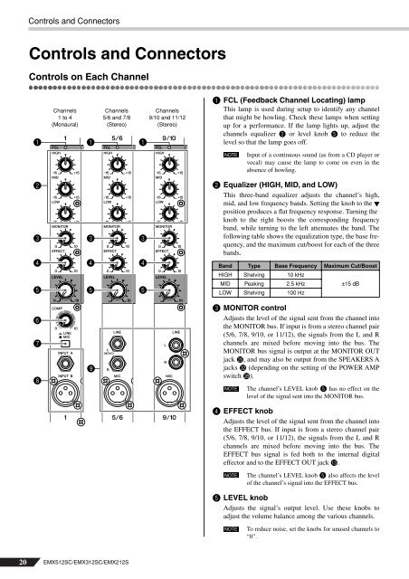
Controls on Each Channel<br />
1<br />
2<br />
3<br />
4<br />
5<br />
6<br />
7<br />
8<br />
Channels<br />
1 to 4<br />
(Monaural)<br />
1<br />
3<br />
4<br />
5<br />
9<br />
Channels<br />
5/6 and 7/8<br />
(Stereo)<br />
20 EMX512SC/EMX312SC/EMX212S<br />
1<br />
3<br />
4<br />
5<br />
Channels<br />
9/10 and 11/12<br />
(Stereo)<br />
1 FCL (Feedback Channel Locating) lamp<br />
This lamp is used during setup to identify any channel<br />
that might be howling. Check these lamps when setting<br />
up for a performance. If the lamp lights up, adjust the<br />
channels equalizer 2 or level knob 5 to reduce the<br />
level so that the lamp goes off.<br />
NOTE<br />
Input of a continuous sound (as from a CD player or<br />
vocal) may cause the lamp to come on even in the<br />
absence of howling.<br />
2 Equalizer (HIGH, MID, and LOW)<br />
This three-band equalizer adjusts the channel’s high,<br />
mid, and low frequency bands. Setting the knob to the<br />
position produces a flat frequency response. Turning the<br />
knob to the right boosts the corresponding frequency<br />
band, while turning to the left attenuates the band. The<br />
following table shows the equalization type, the base frequency,<br />
and the maximum cut/boost for each of the three<br />
bands.<br />
Band Type Base Frequency Maximum Cut/Boost<br />
HIGH Shelving 10 kHz<br />
MID Peaking 2.5 kHz<br />
LOW Shelving 100 Hz<br />
3 MONITOR control<br />
Adjusts the level of the signal sent from the channel into<br />
the MONITOR bus. If input is from a stereo channel pair<br />
(5/6, 7/8, 9/10, or 11/12), the signals from the L and R<br />
channels are mixed before moving into the bus. The<br />
MONITOR bus signal is output at the MONITOR OUT<br />
jack O, and may also be output from the SPEAKERS A<br />
jacks V (depending on the setting of the POWER AMP<br />
switch R).<br />
NOTE<br />
±15 dB<br />
The channel’s LEVEL knob 5 has no effect on the<br />
level of the signal sent into the MONITOR bus.<br />
4 EFFECT knob<br />
Adjusts the level of the signal sent from the channel into<br />
the EFFECT bus. If input is from a stereo channel pair<br />
(5/6, 7/8, 9/10, or 11/12), the signals from the L and R<br />
channels are mixed before moving into the bus. The<br />
EFFECT bus signal is fed both to the internal digital<br />
effector and to the EFFECT OUT jack C.<br />
NOTE<br />
The channel’s LEVEL knob 5 also affects the level<br />
of the channel’s signal into the EFFECT bus.<br />
5 LEVEL knob<br />
Adjusts the signal’s output level. Use these knobs to<br />
adjust the volume balance among the various channels.<br />
NOTE<br />
To reduce noise, set the knobs for unused channels to<br />
“0”.