1.0 - SATA-IO
1.0 - SATA-IO
1.0 - SATA-IO
- No tags were found...

Create successful ePaper yourself
Turn your PDF publications into a flip-book with our unique Google optimized e-Paper software.
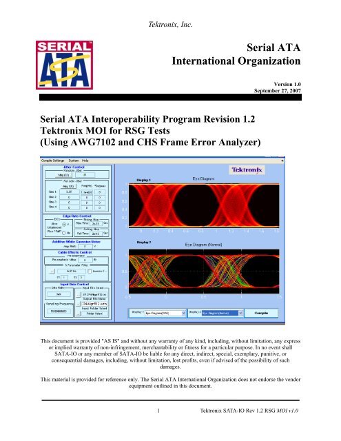
Tektronix, Inc.Serial ATAInternational OrganizationVersion <strong>1.0</strong>September 27, 2007Serial ATA Interoperability Program Revision 1.2Tektronix MOI for RSG Tests(Using AWG7102 and CHS Frame Error Analyzer)This document is provided "AS IS" and without any warranty of any kind, including, without limitation, any expressor implied warranty of non-infringement, merchantability or fitness for a particular purpose. In no event shall<strong>SATA</strong>-<strong>IO</strong> or any member of <strong>SATA</strong>-<strong>IO</strong> be liable for any direct, indirect, special, exemplary, punitive, orconsequential damages, including, without limitation, lost profits, even if advised of the possibility of suchdamages.This material is provided for reference only. The Serial ATA International Organization does not endorse the vendorequipment outlined in this document.1 Tektronix <strong>SATA</strong>-<strong>IO</strong> Rev 1.2 RSG MOI v<strong>1.0</strong>
Tektronix, Inc.TABLE OF CONTENTSTABLE OF CONTENTS.........................................................................................2MODIFICAT<strong>IO</strong>N RECORD ..................................................................................3INTRODUCT<strong>IO</strong>N....................................................................................................5DETAILED TESTS..................................................................................................6TEST RSG-01 - GEN1 (1.5GB/S)RECEIVER JITTER TEST .............................................................. 6TEST RSG-02 – GEN2 (3 GB/S) RECEIVER JITTER TEST............................................................... 8APPENDIX A – RESOURCE REQUIREMENTS .............................................10APPENDIX B – TEST SETUPS...........................................................................11DRIVE RECEIVER TESTS USING BIST-FIS ................................................................................... 11HOST RECEIVER TESTS USING BIST-FIS..................................................................................... 12APPENDIX C – MEASUREMENT CALIBRAT<strong>IO</strong>N .......................................12APPENDIX D – AWG-7102 SETUPS ..................................................................19APPENDIX E – FRAME ERROR DETECTOR................................................20APPENDIX F – ARBITRARY WAVEFORM GENERATOR ACCURACY ..222 Tektronix <strong>SATA</strong>-<strong>IO</strong> Rev 1.2 RSG MOI v<strong>1.0</strong>
Tektronix, Inc.MODIFICAT<strong>IO</strong>N RECORDSeptember 6, 2006 (Version 0.7) INITIAL RELEASEMike Martin, John Calvin: RSG MOI contributionsSeptember 7, 2006 (Version 0.71) Updated Test Setup information in Appendix BMike MartinSeptember 19, 2006 (Version 0.72) Updated to reflect the omission of the SSC margin test, and decisions around focusing thetests around 10, 62 and 5 MHZ and increasing the time interval to 20 minutes each.John CalvinSeptember 20, 2006 (Version 0.8) Reviewed by <strong>SATA</strong> IW working group and incorporated comments.John CalvinNovember 15, 2006 (Version 0.81) Revised CHS Frame Error Detector nomenclature.John Calvin, Daniel Jackson (CHS)December 14, 2006 (Version 0.82) 2’nd round of review by <strong>SATA</strong> IW .John CalvinApril 4, 2007 (Version 0.83) Third round to incorporate introduction of 33 MHZ Sj term, removal of 5MHz termand amplitude calibration methods (Minimum and Maximum).April 26, 2007 (Version 0.90) Incorporated feedback from review session, clarified the dependency on the true413 bit pattern required for amplitude measurements and added new logo.July 12, 2007 (Version <strong>1.0</strong>RC) released for general membership review.September 26, 2007 (Version <strong>1.0</strong>) Revised after 90 day general membership review, and submitted forinclusion with the <strong>SATA</strong> 1.2 IW test program.Chris Skach3 Tektronix <strong>SATA</strong>-<strong>IO</strong> Rev 1.2 RSG MOI v<strong>1.0</strong>
Tektronix, Inc.ACKNOWLEDGMENTSThe <strong>SATA</strong>-<strong>IO</strong> would like to acknowledge the efforts of the following individuals in the development of thistest suite.Tektronix, Inc. – Creation of this documentJohn CalvinMike MartinChris SkachUNH <strong>IO</strong>L. –Provider of the <strong>SATA</strong> Framed Composite pattern.Andrew Baldman4 Tektronix <strong>SATA</strong>-<strong>IO</strong> Rev 1.2 RSG MOI v<strong>1.0</strong>
Tektronix, Inc.INTRODUCT<strong>IO</strong>NThe tests contained in this document are organized in order to simplify the identification ofinformation related to a test, and to facilitate in the actual testing process. Tests are separatedinto groups, primarily in order to reduce setup time in the lab environment, however the differentgroups typically also tend to focus on specific aspects of device functionality.The test definitions themselves are intended to provide a high-level description of themotivation, resources, procedures, and methodologies specific to each test. Formally, each testdescription contains the following sections:PurposeThis document outlines precise and specific procedures required to conduct <strong>SATA</strong> IW1.2 tests, as they pertain to receiver testing. This document covers the following testswhich are all based around testing the receiver channel using a directly synthesizedframed composite pattern with a precise level of digital impairment using an ArbitraryWaveform Generator.The actual framed Composite pattern utilized is a synthesized version of the patternoutlined in the <strong>SATA</strong>_Pretest_MOI revision 1.2.Test CoveragePhy Receiver Signal Requirements (RSG 1-2), as specified in section 2.15 of the UnifiedTest Document revision 1.2.DocumentsReference the Serial ATA document repository found athttp://www.serialata.org/testing.asp for most current versions of these documents.5 Tektronix <strong>SATA</strong>-<strong>IO</strong> Rev 1.2 RSG MOI v<strong>1.0</strong>
Test RSG-01 - Gen1 (1.5Gb/s)Receiver Jitter TestTektronix, Inc.Detailed TestsPurpose: To verify that the <strong>SATA</strong> Gen1 and Gen2 PUT will receive a 1.5Gbps stressed data pattern withoutreceive errors.References:[1] <strong>SATA</strong> Standard revision 2.5, 7.2.1, Table 24 – Lab-Sourced Signal (for Receiver Tolerance Testing)[2] Ibid, 7.2.2.6.7 –[3] Ibid, 7.3 - Jitter[4] Ibid, 7.4.1 – Frame Error Rate[5] Ibid, 7.4.9 – Receiver Tolerance[6] <strong>SATA</strong> unified test document, 2.15.1Resource Requirements:See appendix ASignal Calibration:See appendix C.3 for Amplitude calibration Note: this step should precede the Jitter Calibration steps.See appendix C.1 for Rj calibrationSee appendix C.2 for Tj calibrationSee appendix C4 for Transition time validation.Last Template Modification: September 6, 2006 (Version <strong>1.0</strong>)Discussion:Reference [1] specifies the general RSG conformance limits for <strong>SATA</strong> devices. This specification includesconformance limits for the Receiver Amplitude. Reference [2] provides the definition of Frame Error Rate for thepurposes of <strong>SATA</strong> receiver testing. Reference [4] defines the measurement requirements for this test.Test Setup:Connect equipment as shown in Appendix B, figure 1 or 2 as appropriate.Use AWG Framed Long COMP Receiver Test Pattern library of stressed data patterns outlined in Appendix D. Thislibrary includes 1.5Gbps stressed patterns with sine Dj source frequencies of:10MHz33MHz62MHzTest Procedure:This procedure should be applied to the worst case port (in a multi-port system/host) as determined through theworst case port identification MOI.If necessary, use ancillary equipment to place the <strong>SATA</strong> product-under-test (host or drive) in BIST-L mode .Note: In most cases the AWG will complete the entire process from OOB sequencing to BIST-L, and finally issuinga repeating Framed COMP pattern. In certain cases, it may be necessary to use ancillary equipment to properlyinitiate BIST-L modes of operation..Once in BIST-L mode, connect the AWG to the PUT.6 Tektronix <strong>SATA</strong>-<strong>IO</strong> Rev 1.2 RSG MOI v<strong>1.0</strong>
Tektronix, Inc.To validate that the frame error counting HW is functioning properly, recall the error injector (1 Frame Error)framed comp pattern. (SFCP_1ERR_Clean.wfm from the <strong>SATA</strong>-Gen1-RSG-Compliance.awg setup ). Observe thatthe frame error counter increments by one every time the AWG Run button is pressed. Clear the error counters backto 0 once this has been validated.Recall the clean (no jitter) framed comp pattern (SFCP_0ERR_Clean.wfm from the <strong>SATA</strong>-Gen1-RSG-Compliance.awg setup) and run to observe that no frame error count increments are occurring for 1 minute of initialoperation.For each of the three sine jitter (SJ) frequencies defined, apply the appropriate Stressed Framed COMP patternsoutlined in Appendix D to the PUT. Perform the Frame Error Count test for each frequency for a period of 20minutes. Record Frame Error Count for each jitter frequency.Test pattern setup file :<strong>SATA</strong>-Gen1-RSG-Compliance.awg<strong>SATA</strong> usage model:1.5Gbps(Gen1)Observable Results:Accuracy:Frame Error Counter must record 0 frame errors over a 20 minute period at each of the prescribed jitterfrequencies. Record the number of observed errors at each of the three phases of this test.Possible Problems:7 Tektronix <strong>SATA</strong>-<strong>IO</strong> Rev 1.2 RSG MOI v<strong>1.0</strong>
Tektronix, Inc.Test RSG-02 – Gen2 (3 Gb/s) Receiver Jitter TestPurpose: To verify that the <strong>SATA</strong> Gen2 PUT will receive a stressed data pattern without receive errors.References:[1] <strong>SATA</strong> Standard revision 2.5, 7.2.1, Table 24 – Lab-Sourced Signal (for Receiver Tolerance Testing)[2] Ibid, 7.2.2.6.8 –[3] Ibid, 7.3 - Jitter[4] Ibid, 7.4.1 – Frame Error Rate[5] Ibid, 7.4.9 – Receiver Tolerance[6] <strong>SATA</strong> unified test document, 2.15.2Resource Requirements:See appendix A.Signal Calibration:See appendix C.3 for Amplitude calibration Note: this step should precede the Jitter Calibration steps.See appendix C.1 for Rj calibrationSee appendix C.2 for Tj calibrationSee appendix C4 for Transition time validation.Last Template Modification: September 6, 2006 (Version <strong>1.0</strong>)Discussion:Reference [1] specifies the general RSG conformance limits for <strong>SATA</strong> devices. This specification includesconformance limits for the Receiver Amplitude. Reference [2] provides the definition of Frame Error Rate for thepurposes of <strong>SATA</strong> receiver testing. Reference [4] defines the measurement requirements for this test.Test Setup:Connect equipment as shown in Appendix B, figure 1 or 2 as appropriate.Use AWG Framed Long COMP Receiver Test Pattern library of stressed data patterns. This library includes 3Gbpsstressed patterns with sine Dj source frequencies of:10MHz33MHz62MHzTest Procedure:This procedure should be applied to the worst case port (in a multi-port system/host) as determined through theworst case port identification MOI.If necessary, use ancillary equipment to place the <strong>SATA</strong> product-under-test (host or drive) in BIST-L mode .Note: In most cases the AWG will complete the entire process from OOB sequencing to BIST-L, and finally issuinga repeating Framed COMP pattern. In certain cases, it may be necessary to use ancillary equipment to properlyinitiate BIST-L modes of operation..Once in BIST-L mode, connect the AWG to the PUT.8 Tektronix <strong>SATA</strong>-<strong>IO</strong> Rev 1.2 RSG MOI v<strong>1.0</strong>
Tektronix, Inc.To validate that the frame error counting HW is functioning properly, recall the error injector (1 Frame Error)framed comp pattern. (SFCP_1ERR_Clean.wfm from the <strong>SATA</strong>-Gen2-RSG-Compliance.awg setup ). Observe thatthe frame error counter increments by one every time the AWG Run button is pressed. Clear the error counters backto 0 once this has been validated.Recall the clean (no jitter) framed comp pattern (SFCP_0ERR_Clean.wfm from the <strong>SATA</strong>-Gen2-RSG-Compliance.awg setup) and run to observe that no frame error count increments are occurring for 1 minute of initialoperation.For each of the three sine jitter frequencies defined, apply the appropriate Stressed Framed COMP patterns outlinedin Appendix D to the PUT. Perform the Frame Error Count test for each frequency for a period of 20 minutes.Record Frame Error Count for each jitter frequency.Test pattern setup file :<strong>SATA</strong>-Gen2-RSG-Compliance.awg<strong>SATA</strong> usage model:3Gbps(Gen2)Observable ResultsFrame Error Counter must record 0 frame errors over a 20 minute period at each of the prescribed jitterfrequencies.Accuracy:Possible Problems:9 Tektronix <strong>SATA</strong>-<strong>IO</strong> Rev 1.2 RSG MOI v<strong>1.0</strong>
Tektronix, Inc.Appendix A – Resource RequirementsThe resource requirements include two separate sets of equipment. The equipment required for PHY and TSG testsis shown in section A.1, and the equipment required for TX and RX tests is shown in section A.2, and the equipmentrequired for OOB tests is shown in section A.3.A.1 Equipment for verifying Signal Source Calibration1. Real-time Digital OscilloscopeDPO/DSA71254 (or higher), TDS6154C, TDS612C, or TDS6804B (gen1 only!)2. Test FixtureCrescent Heart Software Fixture TF-<strong>SATA</strong>-NE-XP, TF-<strong>SATA</strong>-NE-ZPor equivalent3. Cables179-4944-00 for valid results using the distributed AWG setup files4. SoftwareTektronix AWG7000 Framed Long COMP Receiver Test Pattern libraryTektronix TDSJIT3v2Tektronix TDSRT-Eye (RTeye version 2.0.3 or later, SST version 1.1.2 or later)A.2 Equipment for Performing Receiver Tests1. Signal GeneratorAWG7102, option 6 and 1 (interleaved output with 20Gs/s sample rate)2. Frame Error CounterCrescent Heart Software <strong>SATA</strong>-II Probe Adapter3. Test Fixture4. Cables5. AttenuatorsCrescent Heart Software Fixture TF-<strong>SATA</strong>-NE-ZPor equivalent179-4944-00 for valid results using the distributed AWG setup files.Two 6 dB (2:1) attenuators should inserted at the end of the cables from the AWG attachingto the inputs of the fixtures. Part number (Tek) 015-1001-01 are recommended.6. <strong>SATA</strong> BISTFIS initialization systemAny system capable of controlling Gen1 and Gen2 products-under-test (PUT), and capable ofplacing the PUT into BIST-L mode. For host testing, this could be a system such as the Catalyst<strong>SATA</strong> analyzer and device emulator. For drive testing, this could be a system such as the UlinkDriveMaster running on a <strong>SATA</strong> capable host system. It is possible that the AWG7000 might beused to perform the BIST-L setup, as well as provide the stressed data pattern for receiver testing.It is also acceptable to utilize proprietary solutions to meet this requirement.7. SoftwareTektronix AWG7000 Framed Long COMP Receiver Test Pattern libraryftp://ftp.tek.com/outgoing/<strong>SATA</strong>-Gen2-RSG-Compliance.zipftp://ftp.tek.com/outgoing/<strong>SATA</strong>-Gen1-RSG-Compliance.zip10 Tektronix <strong>SATA</strong>-<strong>IO</strong> Rev 1.2 RSG MOI v<strong>1.0</strong>
Tektronix, Inc.Appendix B – Test SetupsDrive receiver tests using BIST-FISOnce the Device or Drive DUT has been put in BIST-L mode, the Framed Long COMP pattern is applied with theAWG7102, and the frame errors are counted using the Crescent Heart Software <strong>SATA</strong>-II Probe Adapter using thefollowing configuration:Figure 1: Test the drive receiver using BIST-LFixture Pinout InfoFor DRIVE connectionJ2 J3 J4 J5Rx+ Rx- Tx- Tx+S2 S3 S5 S611 Tektronix <strong>SATA</strong>-<strong>IO</strong> Rev 1.2 RSG MOI v<strong>1.0</strong>
Tektronix, Inc.Host receiver tests using BIST-FISOnce the Host DUT has been put in BIST-L mode, the AWG7102 is set to generate the Framed Long COMPpattern. Frame Errors are counted by the Crescent Heart Software <strong>SATA</strong>-II Probe Adapter.Figure 2: Test the transmitter host DUT using BIST FIS/User methodFixture Pinout InfoFor HOST connectionJ2 J3 J4 J5Tx+ Tx- Rx- Rx+S2 S3 S5 S612 Tektronix <strong>SATA</strong>-<strong>IO</strong> Rev 1.2 RSG MOI v<strong>1.0</strong>
Tektronix, Inc.Appendix C – Measurement CalibrationCalibration:Figure 1: AWG sequence table for the setup file <strong>SATA</strong>-G2-RSG-Compliance.awg illustrating three principalsets of waveforms. 1. BIST-L initiator, 2. .45UI test vectors and 3. Various diagnostic vectors.After recalling the <strong>SATA</strong>-Gn-RSG-Compliance.awg setup , with the output of the AWG directed into CH1 and CH3of Tektronix Oscilloscope (JNB) as outlined in appendix A.1, One may select the various test or diagnostic vectorssequentially and verify the overall system calibration.Test Vectors can be individually selected by clicking on the desired sequence and with a right click perform a AWG” force jump here” operation. As these patterns are sequenced for infinite repetition, they will remain in this stateuntil user intervention occurs.Jitter measurements will be performed using TDSJIT3.V2 using a DATA-TIE (Time Interval Error) without a PLLconfiguration.13 Tektronix <strong>SATA</strong>-<strong>IO</strong> Rev 1.2 RSG MOI v<strong>1.0</strong>
Tektronix, Inc.Setups for Jit3V2:ftp://ftp.tek.com/outgoing/<strong>SATA</strong>-RSG-Gen-1-Calibration.zipor ftp://ftp.tek.com/outgoing/<strong>SATA</strong>-RSG-Gen-2-Calibration.zipUsing the appropriate setup files to conduct the following Rj, and Tj jitter calibration steps.C.1 RJ CalibrationA reference Gen1 and Gen2 MFTP pattern (MFTP-Rj-Cal.wfm) is provided in the AWG bases RSG waveformlibrary support package to facilitate verification of calibration of Rj. Rj is specified to be .18UI PtP @ 7 Sigma or4.285pSec RMS for Gen2 signaling rates and correspondingly 8.57pSec for Gen1 signaling rates.The RJ found in the Tektronix AWG MFTP pattern has been synthesized and is a truncated Gaussian distributionwith the truncation occurring at 5 Sigma.Before performing the Rj calibration verification process, perform a SPC calibration on the Tektronix oscilloscopeused to host JIT3 and perform a D/A channel calibration on the AWG to ensure instrument environmental conditionshave been compensated for.Figure 3: Average Rj value along with a jitter spectrum plot showing Rj content out to Nyquist.14 Tektronix <strong>SATA</strong>-<strong>IO</strong> Rev 1.2 RSG MOI v<strong>1.0</strong>
Tektronix, Inc.As is illustrated in red circled area of Figure 2, ensure the averaged RJ is nominally reading 4.285pSec RMS +- 4%allowable variation. 4.11pSec < Nominal Value < 4.45pSec. The provided setup file will analyze 16E6 contiguouspoints per measurement, and 3 runs will typically converge on a averaged RJ close to 4.285pSec. Jitter magnitudesin excess of these values should result in re-calibration of the AWG.For Gen-1 rates the nominal variation of Rj would be within 8.22 < Nominal Tj Value < 8.9).C.2 TJ CalibrationThe required test waveforms for both Gen1 and Gen2 have been pre-synthesized are provided in the AWG basedRSG waveform library support package. These base patterns conform to the IW sanctioned Framed Compositepattern outline in the <strong>SATA</strong>_Pretest_MOI revision 1.2.After instructing the AWG sequencer to step to any of the provided SCFP-xxMHz-0.45-UITJ test vectors, Jit-3should be run and the Total jitter (Total @ BER (Pk-Pk) observed.Nominal accuracy of a calibrated system will provide .45UI conformance within 4% of nominal error.Figure 3: TIE RjDj-BER result Tab for DATA-TIE jitter measurements.Observe the averaged Total @ BER (Pk-Pk) Jitter value after three acquisitions. The nominal accuracy of acalibrated system will provide .45UI Tj conformance within 4% of nominal error. As such The observed jitter forGen 2 signaling Tj should nominally be 149.9pSec of Tj +- 4% allowable variation. 144pSec < Nominal Tj Value< 155.8 pSec. Jitter magnitudes in excess of these values should result in re-calibration of the AWG.For Gen-1 rates the nominal variation of a Nominal value of Tj would be within 288 < Nominal Tj Value
Tektronix, Inc.C.3 Amplitude CalibrationSignal amplitude conformance requires that Gen 1 and Gen 2 signaling not exceed 600mV or 750mV ptp and bewithin 5% of a target minimum amplitude of 325 and 275mV respectively.The AWG RSG setup files such as <strong>SATA</strong>-Gn-RSG-Compliance.awg provide a set of test vectors with predefinedminimum amplitude. Fine adjustment may be performed by adjusting the Vertical amplitude setting on the AWG’sCH1 output.The minimum amplitude measurements are performed on both 212141 (negative pulse) and 413 (positive pulse)RL patterns.Reference <strong>SATA</strong> specifications on LBP based amplitude measurements.The minimum amplitude over a 1UI epoch is the two consecutive bits at the string of a four or more consecutivebits, which is not a representative LBP pattern but is the minimum value in Framed Composite (Pre-ECN18)pattern.A .45UI to .55UI Histogram is setup on the two lone bits of interest from which the difference of the mean values iscomputed to obtain the lone pulse amplitudes.16 Tektronix <strong>SATA</strong>-<strong>IO</strong> Rev 1.2 RSG MOI v<strong>1.0</strong>
Tektronix, Inc.413 (One) LBP Sequence212141 (Zero) LBP SequenceIn this example the difference in the mean histograms is 278.4mv where as the similar native instrumentmeasurement offers a value of 280mV.Allowable amplitude values will conform to a range of values of 275mV or 325mV +- 13mV. Vertical channeladjustments can compensate for any deviation form these nominal values.17 Tektronix <strong>SATA</strong>-<strong>IO</strong> Rev 1.2 RSG MOI v<strong>1.0</strong>
Tektronix, Inc.C.4 Transition Time ValidationThe same JIT3 setup files used for Jitter calibration/validation have Rise and Fall time measurements which allowthe user to validate that the transition rate does not exceed 100pSec 20/80.JIT3 screen-shot of Framed-Composite signal transition time18 Tektronix <strong>SATA</strong>-<strong>IO</strong> Rev 1.2 RSG MOI v<strong>1.0</strong>
Tektronix, Inc.Appendix D – AWG-7102 SetupsThe AWG-7102 (with Option 6) arbitrary waveform generator is capable of regenerating a <strong>SATA</strong> FramedComposite pattern with prescribed amount of random and deterministic jitter. These synthesized waveforms areencapsulated in a series of setup files which will recall the waveform pattern to generate, set the proper AWG timebasesettings and set the vertical drive amplitude accordingly. Properly calibrated AWG instruments will exhibit aninstrument to instrument difference of less than 4% variation.These AWG setup files reflect framed composite patters with five different jitter configurations modulated onto theclean pattern. The Total Jitter observed on these patterns will be .5UI of jitter with .32UI ofDeterministic/Sinusoidal jitter and .18UI of Random jitter. The mean transition time for these signals is set to120pSec, and the signal amplitude set to 325mV ppd (Gen1) or 275mV ppd (Gen2).D.1 <strong>SATA</strong> 1.5Gb/Sec AWG7102 setup file descriptions.<strong>SATA</strong>-Gen1-RSG-Compliance.awgD.2 <strong>SATA</strong> 3.0Gb/Sec AWG7102 setup file descriptions.<strong>SATA</strong>-Gen2-RSG-Compliance.awg19 Tektronix <strong>SATA</strong>-<strong>IO</strong> Rev 1.2 RSG MOI v<strong>1.0</strong>
Tektronix, Inc.Appendix E – Frame Error Detector(Crescent Heart Software <strong>SATA</strong>-II Probe Adapter)While there are many methods of capturing <strong>SATA</strong> frame errors, the most inexpensive and easy-to-setup methodoutlined in this procedure utilizes a Crescent Heart Software <strong>SATA</strong>-II probe adapter, functioning as a frame errorrate (FER) detector. The probe adapter, in addition to tracking and tallying frame errors, can also provide detailedbit- and frame-level protocol information when connected to a Tektronix logic analyzer. Note that use of the <strong>SATA</strong>-II in FER applications requires an enabling license (part number <strong>SATA</strong>-II-Option-1).As outlined in Section 9.8 of the <strong>SATA</strong>-II users’ manual, install the <strong>SATA</strong>-II control application on any host PC orinstrument in proximity to the PUT. The <strong>SATA</strong>-II probe adapter must be powered using the provided DC powersupply, and attached via USB cable to the host PC running the control application. After invoking the software theapplication’s main window will be seen, as in Figure A.A – <strong>SATA</strong>-II Main WindowThe controls in the middle column set as shown above are appropriate for any simple Gen-I FER counting objectiveoutlined in this MOI. For Gen-II use, the Initial Host Rx speed Gen2 and Initial Device Rx speed Gen2 checkboxesshould also be enabled.20 Tektronix <strong>SATA</strong>-<strong>IO</strong> Rev 1.2 RSG MOI v<strong>1.0</strong>
Tektronix, Inc.Select Counters on the View pulldown menu and the Counters window will be displayed, as seen in Figure B.B – <strong>SATA</strong>-II Counters WindowEnsure that the periodic update checkbox is checked and 40-bit count statistics will be automatically updated whenthe events occur.21 Tektronix <strong>SATA</strong>-<strong>IO</strong> Rev 1.2 RSG MOI v<strong>1.0</strong>
Tektronix, Inc.Appendix F – Arbitrary Waveform Generator AccuracyTables F.1 outline the system and individual measurement accuracy parameters for the <strong>SATA</strong> measurementsoutlined in his MOI when performed using a AWG 7102 Arbitrary Waveform Generator.Table F.2 Measurement specific performance parameters for current IW RSG measurements.SpecnumberMeasurementAccuracyNotes:RSG-01RSG-02Receiver1.5Gb/SecReceiver3.0Gb/SecTBD.TBD.TBD.TBD.22 Tektronix <strong>SATA</strong>-<strong>IO</strong> Rev 1.2 RSG MOI v<strong>1.0</strong>