Enigma/Odyssey installation manual - MGL Avionics
Enigma/Odyssey installation manual - MGL Avionics
Enigma/Odyssey installation manual - MGL Avionics
- No tags were found...

You also want an ePaper? Increase the reach of your titles
YUMPU automatically turns print PDFs into web optimized ePapers that Google loves.
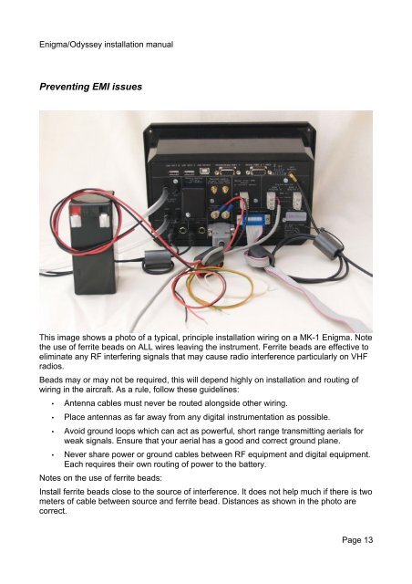
<strong>Enigma</strong>/<strong>Odyssey</strong> <strong>installation</strong> <strong>manual</strong>Preventing EMI issuesThis image shows a photo of a typical, principle <strong>installation</strong> wiring on a MK-1 <strong>Enigma</strong>. Notethe use of ferrite beads on ALL wires leaving the instrument. Ferrite beads are effective toeliminate any RF interfering signals that may cause radio interference particularly on VHFradios.Beads may or may not be required, this will depend highly on <strong>installation</strong> and routing ofwiring in the aircraft. As a rule, follow these guidelines:• Antenna cables must never be routed alongside other wiring.• Place antennas as far away from any digital instrumentation as possible.• Avoid ground loops which can act as powerful, short range transmitting aerials forweak signals. Ensure that your aerial has a good and correct ground plane.• Never share power or ground cables between RF equipment and digital equipment.Each requires their own routing of power to the battery.Notes on the use of ferrite beads:Install ferrite beads close to the source of interference. It does not help much if there is twometers of cable between source and ferrite bead. Distances as shown in the photo arecorrect.Page 13