Enigma/Odyssey installation manual - MGL Avionics
Enigma/Odyssey installation manual - MGL Avionics
Enigma/Odyssey installation manual - MGL Avionics
- No tags were found...
You also want an ePaper? Increase the reach of your titles
YUMPU automatically turns print PDFs into web optimized ePapers that Google loves.
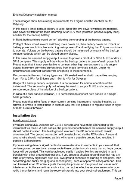
<strong>Enigma</strong>/<strong>Odyssey</strong> <strong>installation</strong> <strong>manual</strong>These images show basic wiring requirements for <strong>Enigma</strong> and the identical set for<strong>Odyssey</strong>.In this case a small backup battery is used. Note that two power switches are required.One power switch for the main incoming 12 or 24 V feed (switch in positive supply lead),another for the backup battery.In flight, both switches would be “on” allowing the charging of the backup battery.Preflight check would involve switching main power on, then battery power on. Check ofbattery power would involve switching main power off and verifying that <strong>Enigma</strong> continuesto operate. Voltage on the backup battery should be measured by means of the backupvoltage readouts which can be placed on any display.In this case the secured supply output is used to power a SP-3, 4 or SP-5 AHRS and/or aSP-2 compass. This supply will draw from the backup battery in case of main power fail.Please note that it is not permissible to connect other high current users to this supplyoutput. Maximum permitted current draw from these terminals is 0.5A. Under nocircumstances connect transceivers or lighting to these terminals.Recommended backup battery types are 12V sealed lead acid with capacities rangingfrom 1Ah to 2.5Ah for <strong>Enigma</strong> and 1.5Ah to 4Ah for <strong>Odyssey</strong>.Usage of a backup battery is optional. It is not required for normal operation of theinstrument. The secured supply output may be used to supply AHRS and compasssensors regardless of <strong>installation</strong> of a backup battery.In case of a dual panel <strong>installation</strong>, it is permissible to connect both panels to a singlebackup battery.Please note that inline fuses or over-current sensing interrupters must be installed asshown. It is wise to install these in such as way that it is possible to replace fuses in flightor reset a circuit breaker.Installation tips:Avoid ground loopsIf you are using <strong>MGL</strong> <strong>Avionics</strong> SP-2,3,4,5 sensors and have them connected to theinstrument via the RCA data cables, the ground connection from the secured supply outputshould not be installed. The black ground wire from the SP sensors should remainunconnected. The ground connection will be established via the RCA cable. A secondground wire should not be used as this will create a possible ground loop resulting inpossible EMI problems.If you are using data or signal cables between electrical instruments in your aircraft thatcontain ground connections, always route these cables in such a way that no large groundloops will be created. This can be achieved easily if cables like this are routed in tightbundles with other ground connections. If you create a physical ground loop that has anyform of physically significant area (i.e. Two ground connections starting at one point, thenseparating and finally merging at a second point), such a loop forms a loop antenna. Thiscan transmit small RF noise signals thatmay be present on the ground and cause radiointerference. At the same time, such a loop can act as effective receive antenna for yourradio transmissions and route the received signals into your electrical equipment. This canPage 9


