Scroll Compressor Application Guidelines - Desco Energy
Scroll Compressor Application Guidelines - Desco Energy
Scroll Compressor Application Guidelines - Desco Energy
- No tags were found...

Create successful ePaper yourself
Turn your PDF publications into a flip-book with our unique Google optimized e-Paper software.
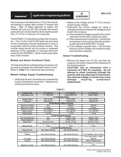
AE4-1318the compressor will start and run. If not, the modulewill attempt a restart after another 5 minute timedelay. After 10 failed attempts to restart, themodule will lock-out (M1-M2 contacts will remainopen) and can only be reset by removing the powerfrom T1-T2 for a minimum of 5 seconds.The INT69SCY is intended to protect the compressor.The L1/L2/L3 and S1/S2 leads are pre-wiredon the compressor and are engineered to work inconjunction with the motor protector module. Themodule leads should not be moved or extendedbecause of the possibility of inducing electronicnoise into the INT69SCY, which could cause falsetrips of the module.Module and Sensor Functional CheckThe following field troubleshooting procedure canbe used to evaluate the solid state control circuit:Refer to Table 7 for a technical data summary.Module Voltage Supply Troubleshooting• Verify that all wire connectors are maintaininga good mechanical connection. Replace anyconnectors that are loose.• Measure the voltage across T1-T2 to ensureproper supply voltage.• Determine the control voltage by using avoltmeter and then measure the voltage acrossthe M1-M2 contacts:a) If the measured voltage is equal to the controlvolts then the M1-M2 contacts are open.b) If the measurement is less than 1 volt and thecompressor is not running, then the problemis external to the INT69-SCY module.c) If the voltage is greater than 1 volt but lessthan the control voltage, the module is faultyand should be replaced.Sensor Troubleshooting• Remove the leads from S1-S2, and then byusing an ohmmeter measure the resistance ofthe incoming leads.CAUTION: Use an Ohmmeter with amaximum of 9 VDC for checking – do notattempt to check continuity through thesensors with any other type of instrument.Any external voltage or current may causedamage requiring compressorreplacement.TABLE 7Copeland P/N 071-0520-07 071-0520-05 071-0547-01Manufacture P/N T.I. 30AA201E Kriwan 69SC-DV Kriwan 69SCYVoltage Supply 120V & 240VT1-T2 Module Power120V & 240V 120V & 240VFrequency 50Hz 60 Hz 50Hz 60 Hz 50Hz 60 HzM1-M2 Module Output ContactsMaximum Voltage N/A 250VAC 250VACMaximum Current 5 Amps 5 Amps 5 AmpsMinimum Current 100 milliamps 100 milliamps 100 milliampsRelay Output 2.5 A, 600 V 5 A, 300 VA 5 A, 300 VAPower Output < 5.5 VA < 3 VA < 3 VAS1-S2 Thermal ProtectionTrip Out Resistance N/A 4500Ω ± 20% 4500Ω ± 20%Reset Resistance N/A 2750Ω ± 20% 2750Ω ± 20%Reset Time 30 min ± 5 min. 30 min ± 5 min. 30 min ± 5 min.T1-T2 interrupt for minimum of T1-T2 interrupt for minimum of T1-T2 interrupt for minimum ofManual Reset5 sec5 sec5 secL1-L2-L3 Phase MonitoringPhase Sensor Non Phase Sensing Non Phase Sensing 3Phase Monitoring CircuitRating Non Phase Sensing Non Phase Sensing 3 AC 50/60Hz 120V to 632VTrip Delay Non Phase Sensing Non Phase Sensing5 min delay before restartattemptLockout Non Phase Sensing Non Phase Sensing After 10 module tripsReset for Lockout Non Phase Sensing Non Phase SensingT1-T2 interrupt for minimum of5 sec5©2002, 2003 Copeland Corporation.Printed in the U.S.A.