Network Camera Server VB101
Network Camera Server VB101
Network Camera Server VB101
- No tags were found...

Create successful ePaper yourself
Turn your PDF publications into a flip-book with our unique Google optimized e-Paper software.
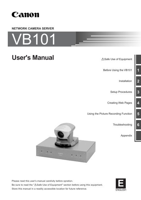
NETWORK CAMERA SERVER<strong>VB101</strong>User's ManualaSafe Use of EquipmentBefore Using the <strong>VB101</strong>InstallationSetup ProceduresCreating Web PagesUsing the Picture Recording FunctionTroubleshooting123456AppendixPlease read this user's manual carefully before opration.Be sure to read the "aSafe Use of Equipment" section before using this equipment.Store this manual in a readily accessible location for future reference.EENGLISH
a Safe Use of EquipmentIntroductionAn exclamation point, within a triangle, is intended to alert the user to the presence of important operatingand maintenance (servicing) instructions in the literature accompanying the equipment.Thank you for purchasing the Canon <strong>Network</strong> <strong>Camera</strong> <strong>Server</strong> <strong>VB101</strong> (referred to hereafter as thesystem).This manual describes how to set up and use the server. Read this manual carefully before usingthe server to ensure effective operation. In particular make sure that you read the "aSafe Use ofEquipment" in this manual, as well as the CD-ROM Readme file.1a Important Warningsa CAUTION:TO REDUCE THE RISK OF ELECTRIC SHOCK, DO NOT REMOVE COVER (OR BACK).NO USER-SERVICEABLE PARTS INSIDE. REFER SERVICING TO QUALIFIEDSERVICE PERSONNEL.Exclusion of LiabilityIf the Product is connected to a recording device (for example a VCR), Canon Inc. accepts noresponsibility whatsoever for any financial losses that may be incurred as a result of the loss ofrecorded information or images, regardless of the internal or external cause of the loss.Copyright InformationVideo or still images recorded using your <strong>VB101</strong> cannot be used in ways that infringe copyrightlaws or without the consent of the owner, unless intended for personal use only.Notes1. The unauthorized transfer of all or any part of the contents of this Manual is forbidden.2. The contents of this Manual are subject to change without notice.3. Every effort has been made to ensure that this Manual is flawless. However, if you find anyoversights, please let us know.4. Item 3. notwithstanding, Canon accepts no responsibility for any effects resulting from the use ofthis Manual.2The serial number of this equipment may be found on the back of the camerahead. No others have the same serial number as yours.You should record the number and other vital information here and retain thisbook as a permanent record of your purchase to aid identification in case of theft.Date of PurchaseDealer Purchased fromDealer AddressDealer Phone No.Model No. <strong>VB101</strong>Serial No.a Important Operational Instructionsa WARNING:a Safe Use of EquipmentTrademark Notices● Canon and Canon logo are registered trademark of Canon Inc.● Microsoft and Windows are registered trademarks of Microsoft Corporation in the United Statesand other countries.● Windows is legally recognized as Microsoft Windows Operating System.● Other brand or product names in this manual may be trademarks or registered trademarks oftheir respective companies.TO REDUCE THE RISK OF ELECTRIC SHOCK, DO NOT EXPOSE THIS EQUIPMENTTO RAIN OR MOISTURE.a CAUTION:TO REDUCE THE RISK OF ELECTRIC SHOCK AND TO REDUCE ANNOYINGINTERFERENCE, USE THE RECOMMENDED ACCESSORIES ONLY.© Copyright 2000 CANON INC.ALL RIGHTS RESERVEDFDA regulationThis communication camera has not been evaluated by the Food and DrugAdministration (FDA) for use as a medical device. When incorporated into asystem with medical applications, FDA regulations may apply. Therefore,please consult your legal advisor to determine whether FDA regulations apply.2 3
a Safe Use of Equipmenta Safe Use of EquipmentFCC NOTICE<strong>Network</strong> <strong>Camera</strong> <strong>Server</strong> <strong>VB101</strong> (D78-0138)3a IMPORTANT SAFETY INSTRUCTIONSThis device complies with Part 15 of the FCC Rules. Operation is subject tothe following two conditions: (1) This device may not cause harmfulinterference, and (2) this device must accept any interference received,including interference that may cause undesired operation.Note: This equipment has been tested and found to comply with the limits fora Class B digital device, pursuant to Part 15 of the FCC Rules. These limitsare designed to provide reasonable protection against harmful interference ina residential installation. This equipment generates, uses and can radiate radiofrequency energy and, if not installed and used in accordance with theinstructions, may cause harmful interference to radio communications.However, there is no guarantee that interference will not occur in a particularinstallation. If this equipment does cause harmful interference to radio ortelevision reception, which can be determined by turning the equipment offand on, the user is encouraged to try to correct the interference by one ormore of the following measures:- Reorient or relocate the receiving antenna.- Increase the separation between the equipment and receiver.- Connect the equipment into an outlet on a circuit different from that to whichthe receiver is connected.- Consult the dealer or an experienced radio/TV technician for help.Use of shielded cable is required to comply with class B limits in Subpart B ofPart 15 of FCC Rules.Do not make any changes or modifications to the equipment unless otherwisespecified in the manual. If such changes or modifications should be made,you could be required to stop operation of the equipment.Canon U.S.A. Inc.One Canon Plaza, Lake Success, NY 11042, U.S.A.Tel No. (516) 328-5600IC NOTICEThis product does not exceed the Class B limits for radio noise emissionsfrom digital apparatus as set out in the Interference-causing equipmentstandard entitled ‘Digital Apparatus’, ICES-003 of the Industry Canada.NOTIFICATION ICCet appareil numériquw respecte les limites de bruits radioélectriquesapplicables aux appareils numériques de Classe B prescrites dans la normasur le matériel brouilleur: “Appareils Numériques”, NMB-003 édictées parI’lndustrie Canada.Dieses Produkt ist zum Gebrauch im Wohnbereich, Geschäfts- undGewerbebereich sowie in Kleinbetrieben vorgesehen.In these safety instructions, the word“equipment” refers to the Canon <strong>Network</strong><strong>Camera</strong> <strong>Server</strong> <strong>VB101</strong> and all itsaccessories.1. Read Instructions - All the safety andoperating instructions should be readbefore the equipment is operated.2. Retain Instructions - The safety andoperating instruction should be retainedfor future reference.3. Heed Warnings - All warnings on theequipment and in the operatinginstructions should be adhered to.4. Follow Instructions - All operating andmaintenance instructions should befollowed.5. Cleaning - Unplug this equipment fromthe wall outlet before cleaning.Wipe the equipment with a clean softcloth. If necessary, put a cloth in dilutedneutral detergent and wring it well beforewiping the equipment with it. Finally,clean the equipment with a clean drycloth. Do not use benzene, thinner orother volatile liquids or pesticides asthey may damage the product’s finish.When using chemically-treated cleaningcloths, observe those precautionsaccordingly.6. Accessories - Do not use accessoriesnot recommended in this manual asthey may be hazardous. Always usespecified connection cables. Connectdevices correctly.7. Water and Moisture - Hazard of electricshock - Do not use the equipment nearwater or in rainy/moist situations. Do notput a heater near this equipment.8. Placing or Moving - Do not place on anunstable cart, stand, tripod, bracket ortable. The equipment may fall, causingserious injury to a child or adult, andserious damage to the equipment. Anequipment and cartcombination shouldbe moved with care.Quick stops, excessive force, anduneven surfaces may cause theequipment and cart combination tooverturn.9. Power Sources - The PA-V16 ACadapter should be operated only fromthe type of power source indicated onthe marking label. If you are not sure ofthe type of power supply to your home,consult your equipment dealer or localpower company.10. Polarization - The PA-V16 AC adapteris equipped with a polarized 2-prongplug (a plug having one blade wider thanthe other).The 2-prong polarized plug will fit intothe power outlet only one way. This is asafety feature. If you are unable to insertthe plug fully into the outlet, try reversingthe plug. If the plug still fails to fit, contactyour electrician to replace your obsoleteoutlet. Do not defeat the safety purposeof the polarized plug.11. Power Cord Protection - Power cordsshould be routed so that they are notlikely to be walked on or pinched byitems placed upon or against them. Payparticular attention to plugs and the pointfrom which the cords exit the equipment.12. Outdoor Antenna Grounding - If anoutside antenna is connected to theequipment, be sure the antenna isgrounded so as to provide someprotection against voltage surges andbuilt-up static charges. Section 810 ofthe National Electrical Code, ANSI/NFPA No.70-1984, provides informationwith respect to proper grounding of themast and supporting structure,grounding of the lead-in wire to anantenna discharge unit, size ofgrounding conductors, location ofantenna antenna discharge unit,connection to grounding electrodes,and requirements for the groundingelectrode. See figure 1.a Safe Use of Equipment4 5
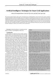
a Safe Use of Equipmenta Safe Use of Equipmentfig-1EXAMPLE OF ANTENNA GROUNDING ASPER NATIONAL ELECTRICAL CODEGROUNDINGCLAMPELECTRICSERVICEEQUIPMENTNEC — NATIONAL ELECTRIC CODEANTENNALEAD IN WIREANTENNADISCHARGEUNIT (NECSECTION 810-20)GROUNDINGCONDUCTORS(NEC SECTION810-21)GROUNDING CLAMPSPOWER SERVICEGROUNDING ELECTRODESYSTEM(NEC ART 250. PART H)13. Lightning - For added protection of thisequipment during a lightning storm, orwhen it is left unattended and unusedfor long periods of time, disconnect itfrom the wall outlet and disconnect theantenna. This will prevent damage tothe equipment due to lightning andpower-line surges.14. Power Lines - An outside antennasystem should not be located in thevicinity of overhead power lines orother electric light or power circuits,or where it can fall into such powerlines or circuits. When installing anoutside antenna system, extreme careshould be taken to keep from touchingsuch power lines or circuits as contactwith them might be fatal.15. Overloading - Do not overload walloutlets and extension cords as this canresult in a risk of fire or electric shock.16. Object and Liquid Entry - Never pushobjects of any kind into this equipmentthrough openings as they may touchdangerous voltage points or short outparts that could result in a fire orelectric shock. Be careful not to spillliquid of any kind onto the equipment.17. Servicing - Do not attempt to servicethis equipment yourself as opening orremoving covers may expose you todangerous voltage or other hazards.Refer all servicing to qualifiedpersonnel.18. Damage Requiring Service - Disconnectthis equipment from the wall outlet andall power sources including batteries, andrefer servicing to qualified servicepersonnel under the following conditions.a. When the power-supply cord or plugis damaged.b. If any liquid has been spilled onto, orobjects have fallen into, theequipment.c. If the equipment has been exposedto rain or water.d. If the equipment does not operatenormally even if you follow theoperating instructions. Adjust onlythose controls that are covered by theoperation instructions. Improperadjustment of other controls mayresult in damage and will often requireextensive work by a qualifiedtechnician to restore the equipmentto its normal operation.e. If the equipment has been droppedor the cabinet has been damaged.f. When the equipment exhibits adistinct change in performance. Thisindicates a need for service.19. Replacement Parts - When replacementparts are required, be sure the servicetechnician has used replacement partsthat are specified by Canon or that havethe same characteristics as the originalpart. Unauthorized substitutions mayresult in fire, electric shock or otherhazards.20. Safety Check - Upon completion of anyservice or repairs to this equipment, askthe service technician to perform safetychecks to determine that the equipmentis in safe operating order.21. Do not install the equipment in thefollowing locations as this can cause afire or electric shock:- Hot locations- Close to a fire- Very humid or dusty locations- Locations exposed to direct sunlight- Locations exposed to salt spray- Close to flammable solvents (alcohol,thinners, etc.)22. When any of the following occurs,immediately switch OFF the equipment,unplug it from the main power supplyand contact your nearest Canonsupplier. Do not continue to use theequipment as this can cause a fire orelectric shock.- The equipment emits any smoke,heat, abnormal noise, or unusualodor.- A metal object falls into theequipment.- The equipment is damaged in someway.23. Please observe the following whenusing the equipment. Failure to do socan result in a fire or electric shock.- Do not use flammable sprays nearthe equipment.- Do not subject the equipment tostrong impacts.24. Please observe the following whenhandling the batteries. Failure to do socan result in the batteries bursting oremitting heat, sparks or corrosive fluid.- Do not throw the batteries into a fire,and do not heat, short-circuit orattempt to disassemble the batteries.- Do not attempt to recharge thebatteries.- Do not use batteries other than thosespecified for use with the equipment.25. Please observe the following whenhandling the batteries. Failure to do somay result in the batteries bursting oremitting heat, sparks or corrosive fluid.- When the batteries are used up, orwhen the equipment will not be usedfor an extended period, remove thebatteries.- When replacing the batteries, alwaysreplace both batteries, and do not usedifferent types of batteries together.- Ensure that the + and - terminals arecorrectly positioned when you loadthe batteries.- If any soiling or leakage of the internalbattery fluid occurs, thoroughly cleanthe soiling or leaked fluid with water.6 7a Safe Use of Equipment
a Safe Use of EquipmentContentsIntroduction4 MaintenanceCleaning the Equipment1. Unplug the AC adapter from the wall outlet.2. Carefully wipe the equipment with a soft cloth that has been moistenedwith water or a mild detergent.WARNINGDo not use flammable solvents such as alcohol, benzene or thinners.The use of such substances can cause a fire or electric shock.3. Wipe with a dry cloth.4. When you have finished, plug the AC adapter back in to the wall outlet.Icons Used in This Instruction ManualIndicates important information that must be observed or actions thatc are prohibited during an operation. These notes must be read toNoteprevent possible faults or damage to the equipment.eTipIndicates supplementary information or a reference to an operation.Users are advised to read these memos.aSafe Use of Equipment1 a Important Warnings ................................................. 32 a Important Operational Instructions .......................... 33 a IMPORTANT SAFETY INSTRUCTIONS ................. 54 Maintenance ................................................................. 8Chapter 1 Before Using the <strong>VB101</strong>Features of the <strong>VB101</strong> .......................................... 12System Configuration .......................................... 14Hardware and Software Requirements............... 16Webview Livescope Viewer Software ........................ 16Webview Livescope MV MonitoringStation Software version 1.0 (optional) ................ 16Compatible <strong>Camera</strong>s (optional) ................................. 17Compatible <strong>Network</strong>s ................................................. 17Compatible PCMCIA Cards ........................................ 17Compatible Cables (optional) ..................................... 17System Components and Their Operation ......... 18Chapter 2 InstallationPackage Contents ................................................. 22Precautions for use .............................................. 23Precautions for Switching the <strong>VB101</strong> On and Off ...... 23Connecting the Components .............................. 24Using a PCMCIA Card .......................................... 25Procedure for Using Flash Memory Cards ................ 25Sample <strong>Network</strong> Configurations ......................... 26Sample LAN Environment Configuration ................... 26Sample Dialup Environment Configuration ................ 26LAN plus Dialup Environment .................................... 27Sample Configuration in an ISP Environment ........... 27Chapter 3 Setup ProceduresInstallation Workflow ............................................ 30Initial Setup ........................................................... 31Checking Operation.............................................. 33Detail Settings ....................................................... 34Accessing the Settings Title Pages ............................ 34Settings Title Page ...................................................... 35Basic Settings Page ................................................... 36Systems Settings Page .............................................. 37<strong>Network</strong> Settings Page ............................................... 38<strong>Camera</strong> and Video Settings Page .............................. 40Preset Settings Page .................................................. 44Picture Recording and External Device I/OSettings Page ....................................................... 458 9Contents
ContentsAccess Control Settings Page .................................... 49Application Settings Page .......................................... 52Miscellaneous Settings Page ..................................... 54Administration Tools Page .......................................... 56Chapter 4 Creating Web PagesWeb Pages for Video Transmission .................... 58Features of the Java Viewers ..................................... 59Features of the Helper Viewer .................................... 61Viewing Sample Pages ......................................... 62Using a Java Viewer to Transmit Video Images .... 63Using a Java Viewer to Create a Web page ............... 63Example of Using a Java Viewer to Create a Web page ... 64Java Viewer Parameters ............................................. 72Using the Helper Viewer to TransmitVideo Images ......................................................... 74Example of a Web page Using the Helper Viewer ..... 76Transmitting Video Images Using aBrowser Only ......................................................... 77Chapter 5 Using the Picture Recording FunctionUsing the Still Picture Recording FunctionLinked to an External Device............................... 80Sample application in combination with adoor-opening sensor and lighting unit ........................ 80Using the Still Picture Recording Functionwith a Predetermined Schedule .......................... 82Sample application in combination with a lighting unit .. 82Viewing and Transmitting Recorded Pictures ... 84Viewing Recorded Pictures ........................................ 84Transmitting Recorded Pictures ................................. 88Chapter 6 TroubleshootingAppendixTroubleshooting .................................................... 90Log Messages ....................................................... 92Specifications ..................................................... 104External Device I/O Terminals .................................. 105Using the Enclosed Software ............................ 106Restoring the Factory Default Settings .................... 106Upgrading the Firmware Remotely .......................... 107Using the Administrator Viewer ................................ 108Factory Default Setting ...................................... 110Index..................................................................... 112Chapter 1Before Using the <strong>VB101</strong>This chapter contains information that you should read beforeusing the <strong>VB101</strong>. It also describes the features of this system, thesystem configuration, the hardware and software requirements,and the name and fonctions of the system components.10
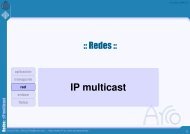
Features of the <strong>VB101</strong>Features of the <strong>VB101</strong>The <strong>VB101</strong> digitalizes images captured from a video camera, allowing easy distribution of these imagesover the Internet or an intranet. The person receiving the images can use the Canon WebView Livescopesoftware (Java version viewer and Helper version viewer) to view the images. If a Canon Communicationcamera is used, a wide range of additional functions are also available, including remote camera controland using a Web page for everything from transmitting video information to video image monitoring.Furthermore, by using this system together with the optional* WebView Livescope MV monitoring viewer, youcan conduct remote monitoring from multiple locations. For more information on how to use the WebViewviewer software and the WebView Livescope MV software, refer to the respective software manuals.*VB-101 can also be used in VIEW-Windows.*VIEW-Windows is a product designed for use within Japan.■High-quality images with a high frame rateThe <strong>VB101</strong> is capable of image capture at speed of up to 30 fps. Image compression is performedusing Motion-JPEG. Because the sender can control the image quality and capture rate, thesettings can be optimized for the network environment. The image quality can be set on a scalefrom 1 to 99, and the capture rate can be set to speeds between 0.1 and 30 fps.■Up to 4 cameras connectedUp to 4 video cameras can be connected to the <strong>VB101</strong> and up to two cameras can be selected forcamera control. <strong>Camera</strong>s can be switched by the viewer and the images from the selectedcamera are displayed. Two RCA sockets are provided as the input interface for video camerasand 2 BNC sockets are provided for cameras commonly used for monitoring. The user canspecify which camera connected to which socket is to be controlled.■Versatile camera controlIf a Canon Communication camera is used, the client can control the angle (pan and tilt) and thezoom ratio of cameras installed in remote locations just as if he or she was actually there. Theclient can also impose operating limits by specifying camera angles that are not to be shown andrestricting the available zoom settings.■Preset function for camera positionsBy registering camera angles specified beforehand, the user can display a scene requested by aclient simply by selecting the specified preset information.■New VC-C4/VC-C4R <strong>Camera</strong>s supportedThe <strong>VB101</strong> can be used with the latest Canon Communication <strong>Camera</strong> VC-C4/VC-C4R (support for reverse suspended installation). This allows the user tocontrol VC-C4/VC-C4R cameras, which provide improved performance andfunctionality, including reverse suspended installation and a larger controlrange than the VC-C3 and VC-C1 MK II.■Internet/intranet compatibilityThe <strong>VB101</strong> software is compatible with TCP/IP and HTTP, the standard Internet protocols, allowingvideo image transmission and remote camera control to be performed easily from a Web browser.The Ethernet interface supports 10 Mbps/100 Mbps autosensing (or auto detection), and a PC card■Simple set up and managementBy accessing a Setup Management page provided on the Web, you can use the Web browser onyour PC to set up and manage the system from a remote location without ever visiting the placewhere the system is actually installed. You can also use the special setup program provided tospecify the initial IP address. IP addresses can be automatically specified in networkenvironments where Bootp can be used.■Log functionsYou can use the logging functions to save log information on events such as faults and accessstatuses to a file and then send that information to a specific e-mail address.■Built-in Web server and FTP serverAs well as transmitting video images, the <strong>VB101</strong> also features built-in Web server functions forWeb pages. By making Web page data to an optional flash memory card, the <strong>VB101</strong> can bealso used to transmit data and video images across the Web. Moreover, because the <strong>VB101</strong>has a built-in FTP server, it is also possible to download Web pages remotely.■Fully expandableThe <strong>VB101</strong> is provided with 2 card slots which you can use to add a modem, or a flash memoryas required.■Concurrent video is distributed up to 20 clientsUp to 20 clients can view video at the same time from a single <strong>VB101</strong>. Also, the number ofconcurrent accesses can be specified on the camera server to suit the available networkbandwidth.■<strong>Camera</strong> control rights to coordinate camera control contentionThe introduction of control rights means that contention can be prevented when multiple videoreceivers are controlling the camera at the same time. The default time for which clients receivingimages have exclusive control of the camera is 20 seconds in the initial factory settings. (Thissetting can be changed from the server.)■More powerful security functionsThe destinations for video transmissions can be restricted based on IP addresses and passwords.■Picture recording function using schedule management and cooperationwith external devicesThe <strong>VB101</strong> is provided with picture recording and digital output functions controlled by presetschedules, along with on/off functions that are triggered by digital input from connected devices.These features expand the range of system applications still further.12 modem can be used to access public switched telephone networks.131Before Using the <strong>VB101</strong>
VC-C4CO MUNICATION CAMERAf:4-64 m 1:1.4-2.8VC-C4CO MUNICATION CAMERAf:4-64 m 1:1.4-2.8VC-C4CO MUNICATION CAMERAf:4-64 m 1:1.4-2.8VC-C4CO MUNICATION CAMERAf:4-64 m 1:1.4-2.8VC-C4CO MUNICATION CAMERAf:4-64 m 1:1.4-2.8VC-C4CO MUNICATION CAMERAf:4-64 m 1:1.4-2.8System ConfigurationSystem ConfigurationExample of Webview Livescope System ConfigurationExample of Webview Livescope MV System ConfigurationSample system configurationVC-C4VC-C4VC-C4<strong>VB101</strong><strong>VB101</strong>InternetEthernet(10/100Mbps)WebView Livescope(Java applet or special helper software)Recommended browser● Netscape Navigator/Communicator4.5 or later● Internet Explorer 4.01 or laterSample System ConfigurationVC-C4VC-C4<strong>VB101</strong>Ethernet(10/100Mbps)WebView Livescope MVWindows98/95/NT4.0/2000(Internet Explorer 5 required)1Webview Livescope is a system, which webcasts live video images shot using a Canon Communication<strong>Camera</strong> (VC-C4, etc) installed in a remote location to computers connected to the Internet or an intranet.Clients can view the received video images simply using a Web browser. And because clients can controlthe cameras remotely from their Web browser via the network, Webview Livescope provides realtimeimages with a true feeling of immediacy.Images from the <strong>VB101</strong> are viewed on a special viewer. Embedding this viewer in a web page greatly expandsthe possibilities of the Internet or intranets, including such functions as monitoring of remote locations using aWeb browser and the creation of striking Web pages, thereby building networks that a more useful to business.Video image receiverViewer (free of charge)■Viewer software types and functionsViewer SoftwareJava ViewerHelper ViewerThis refers to the computer that runs a Viewer module used to viewimages transmitted from the <strong>VB101</strong> on a Web browser. The two types ofviewer module are described in the table below.FunctionsA Web browser that can run Java applets and displays video images from the <strong>VB101</strong>.Because the Java Viewer is automatically downloaded and does not need to be pre-installed, unliketheir helper viewer, it is compatible with any platform that supports Java-capable environments.Because it uses the HTTP protocol, the Java Viewer penetrates firewalls unscathed.However, it may not run stably on some platforms or browser types.Also, because the viewer is downloaded when the Web page loads, start-up times andexecution speeds are slower than the helper viewer.A helper application for viewing video images from the <strong>VB101</strong> that is launched from a Web browser.The helper viewer must be pre-installed.This application can be downloaded free of charge from the CD-ROM provided, or the following Web page.URL: http://www.x-zone.canon.co.jp/WebView-E/download/dload.htmCompared with the Java Viewer, start-up is faster because the viewer does not need to bedownloaded. This viewer is recommended for users who use the viewer frequently.Because it supports the HTTP protocol, the helper Viewer penetrates firewalls unscathed.14 15VC-C4cNote<strong>VB101</strong>WebView Livescope MV provides administration tools and a multi-viewer for an easy-to-use centralizedmonitoring environment that uses multiple <strong>VB101</strong> network cameras.Users can easily create their own monitoring screens from more than 60 screen patterns-almost withoutneeding to refer to the manual, which in turn reduces the time it takes to create a Web page- just byanswering Create Screen Wizard questions. A maximum of 16 locations can be displayed simultaneously ona monitoring screen and users can also use the Map function, Auto switch function and Auto drive function.In addition, you can compile a list of multiple <strong>VB101</strong> cameras to control camera settings, perform versioncontrol and control operation status.■Optional Products• Webview Livescope MV version 1.0■Optional Accessories• Modem card• Flash memory card• PC• Canon Communication <strong>Camera</strong> VC-C4/VC-C4R/VC-C3• Wide Converter WL-37 (for VC-C4), WD-37 (for VC-C3)• Sensor• Relay● To connect the <strong>VB101</strong> to the Internet, you require a leased line connection to anInternet service provider or a LAN-type dialup IP connection. If you are using a LANtypedialup connection, check that the connection supports bidirectional calling.● You need a Web browser to use the <strong>VB101</strong>. Check beforehand that you canuse a Web browser.Before Using the <strong>VB101</strong>
Hardware and Software RequirementsHardware and Software RequirementsWebview Livescope Viewer SoftwareCompatible <strong>Camera</strong>s (optional)Java Viewer version 3.10PCIBM PC/AT compatibleOperating SystemWindows 95/98 or Windows NT 4.0 (IE 4.0 or later required)/Windows 2000Web BrowserNetscape Navigator/Communicator 4.5 or later,or Microsoft Internet Explorer 4.01 or later required* This viewer is installed on the <strong>VB101</strong> and is automatically downloaded by the client at access.* This software may not run stably on operating systems other than those listed above.Canon Communication <strong>Camera</strong>VC-C4/VC-C4R(NTSC)Canon Communication <strong>Camera</strong>VC-C4R(NTSC)Canon Communication <strong>Camera</strong>VC-C3(NTSC/PAL)1Helper Viewer version 3.10PCOperating SystemWeb BrowserIBM PC/AT compatibleWindows 95/98 or Windows NT 4.0 (IE 4.0 or later required)/Windows 2000Netscape Navigator/Communicator 4.5 or later,or Microsoft Internet Explorer 4.01 or later required* This software must be installed beforehand.* It can be installed free of charge from the CD-ROM for the <strong>VB101</strong>, or the following Web site.URL: http://www.x-zone.canon.co.jp/WebView-E/download/dload.htmThe wide converter WL-37 (for the VC-C4) and the wide converter WD-37 (for the VC-C3) areavailable as optional accessories.eTipCompatible <strong>Network</strong>sWhile other cameras can be used, the camera control functions will not beavailable. Only the video functions can be used.Before Using the <strong>VB101</strong>cNoteThe helper viewer or plug-in viewer for Webview Livescope version 1.21, 2.01and 3.0 can also be used, but some of the functions differ.On Macintosh computers, some of the functions of the helper viewer forWebview Livescope version 1.20 are not available.• 10 Base-T/100 Base-TX Ethernet (auto negotiation)• Public switched telephone networks (Use a recommended modem card)Compatible PCMCIA CardsUse a recommended PCMCIA card. For further information, contact your Canon dealer.Webview Livescope MV Monitoring Station Software version 1.0 (optional)Compatible Cables (optional)ComputerOSWeb BrowserIBM PC/AT compatible deviceCPU: Pentium II 266 MHz or better, RAM: 64 Mbytes or better, Hard disk capacity: 300 Mbytes or betterWindows 95/98 or Windows NT 4.0/Windows 2000Microsoft Internet Explorer 5 or later requiredRS-232C cables for camera control and video cables are available as optional accessories inlengths other than the ones provided. For further information, contact your Canon dealer.16 17
System Components and Their OperationSystem Components and Their OperationFront ViewRear ViewPower LEDPowered onSystem faultSlot-A LEDlit greenlit orange(Shows the operation status for card slot A)Normal operation lit greenDuring access lit orangeSlot-B LED(Shows the operation status for card slot B)Normal operation lit greenDuring access lit orangePower Slot-A Slot-B VB 101100 Tx/Lnk Col/RxDc InPower connection socketExternal device I/O terminalsCard slot A(accepts modem card)Card slot B(accepts modem card)100/10 BT Ethernet connector(100Base-TX, 10Base-T automatic detection and switching)Slot-BSlot-ARS232CVideo InCC1 CC2 V1 V2 V3 V41 2 1 2InOutEthernet100/10BT1Before Using the <strong>VB101</strong>100 LED(Shows the Ethernet 100/10 operation mode)100Base-TX lit green10Base-T offTx/Lnk LED(Shows the Ethernet transmission status)Normal connection lit greenDuring transmission lit orangeCol/Rx LED(Shows the Ethernet reciving status)Receiving lit greenCollision lit orangeConsole connector terminalfor initial setup and servicing(RS-232C)<strong>Camera</strong> control connector CC1,CC2(RS-232C, with one touch lock)Video input sockets V1, V2(RCA pin-jack)Video input sockets V3, V4(BNC connector)eTipWhen you power on the <strong>VB101</strong>, the power LED glows orange for severalseconds and then turns green. This is normal and does not indicate a fault.eTipThe video cable supplied with the Canon Communication<strong>Camera</strong> VC-C4/VC-C4R, VC-C3 and VC-C1 MK II is compatiblewith the RCA pin-jack. To connect these cameras to a BNCsocket, use a third party Pin → BNC conversion adapter.18 19
Chapter 2InstallationThis chapter explains how to connect the system components anddescribes a sample network configuration.20
Package ContentsPrecautions for useThe <strong>VB101</strong> package contains the following items. If any of these items is missing, contact theretailer from which you purchased the product.Precautions for Switching the <strong>VB101</strong> On and Off1. <strong>VB101</strong> main unit2. AC Adapter PA-V16The <strong>VB101</strong> has no power switch. To switch the <strong>VB101</strong> off and on, unplug the AC adapter. Whenyou unplug the AC adapter from the <strong>VB101</strong>, wait at least 5 seconds and then plug the AC adapterto the <strong>VB101</strong>. Be sure to observe the precautions given in "aImportant Safety Instructions".AC Outlet3. AC cable (1 meter 3 ft. 3 /32 in.) 4. RS-232C cable (miniDIN-miniDIN)● For camera control, 3 m (9 ft. 10 3 /32 in.)<strong>VB101</strong>AC adapterAC cable2* The cable length may differ depending on thecountry in which the product was purchased.cNote● Refer also to the enclosed ReadMe file. The ReadMe file may containimportant information not included in this manual. Be sure to read this file.● If the <strong>VB101</strong> will not be used for some time, unplug the AC adapter fromthe power supply.Installation5. RS-232C cable(miniDIN-Dsub9pin Female sub)6. CD-ROM● For setup, 3 m (9 ft. 10 3 /32 in.)7. Users Manual (This document)8. Warranty CardCD-ROM contentsReadMe<strong>VB101</strong> Initial Setup ToolsFactory Default Setup ToolsAdministrator ViewerRemote Firmware Upgrade UtilityInternal File SystemWebview Livescope Helper Viewer version 3.1Webview Livescope Viewer User's Manual (PDF file)22 23
VC-C4CO MUNICATION CAMERAf:4-64mm 1:1.4-2.8VC-C4CO MUNICATION CAMERAf:4-64 m 1:1.4-2.8VC-C4CO MUNICATION CAMERAf:4-64 m 1:1.4-2.8VC-C4CO MUNICATION CAMERAf:4-64 m 1:1.4-2.8VC-C4CO MUNICATION CAMERAf:4-64 m 1:1.4-2.8CO MUNICATION CAMERAf:4-64 m 1:1.4-2.8Connecting the ComponentsUsing a PCMCIA CardThe <strong>VB101</strong> has 2 card slots, and you can record Web page data, etc. by inserting a flash memory card intoone of these slots.Initial setup PCCOM portRS-232C cableRS-232C cableVideo cable (RCA)<strong>Camera</strong>VC-C4Procedure for Using Flash Memory Cards1Insert the flash memorycard into the <strong>VB101</strong>.PCMCIAcardRS-232CcableVideo cable (RCA)<strong>Camera</strong>You can insert the card into eitherslot. But if cards are inserted in bothFlash memory card<strong>VB101</strong> rear panelslots, you cannot use both cards at the same time. Preparation is complete when the<strong>VB101</strong> rear panelDc InSlot-BSlot-ARS232CVideo InCC1 CC2 V1 V2 V3 V4LED on the front of the <strong>VB101</strong> changes from green to orange.1 2 1 2InOutEthernet100/10BT<strong>Camera</strong>2Create the directories.Create directories called "htdocs" and "logs", for web page data (hereafter referred to2AC OutletAC adapterAC cableSensor input,relay outputLANcableEthernetVideo cable(BNC)Video cable(BNC)<strong>Camera</strong>3as content) and log data respectively, on the flash memory card. You can create thedirectories using ftp commands or by inserting the flash memory card into a notebookPC and using file operations.Save the content.You can save the content to the flash memory card using either file operations on anotebook PC or remotely using FTP. When a flash memory card is inserted correctly, itInstallationcNotes● The cable connecting the <strong>VB101</strong> and the camera should be no longer than15 meters (49 ft. 2 19 /32 in.), as stipulated in the RS-232C standards. If the cablelength exceeds 15 meters (49 ft. 2 19 /32 in.), system operation is no longerguaranteed.● The video cable supplied with the Canon Communication <strong>Camera</strong> VC-C4/is mounted in the <strong>VB101</strong> file system as a directory called "/card". The content data isstored as files in the /card/htdocs directory (file names made up of eight alphanumericcharacters followed by a three-character extension). Data can also be stored in theflash memory built into the <strong>VB101</strong>. However, due to the limited available space (550kilobytes), only the minimum required amount of data can be stored.VC-C4R, VC-C3 and VC-C1 MK II is compatible with the RCA pin-jack. Toconnect these cameras to a BNC socket, use a third party Pin → BNCconversion adapter. (→ P.19)● To connect a RS-232C cable to the VC-C4/VC-C4R, use the IN socket.DeviceOn-board flashmemoryFile system(accessed by file operations or by an ftp client)ftp://IP address/htdocsURL(accessed from a Web browser)http://IP address/● Though daisy-chain connections are possible under the VC-C4/VC-C4RFlash memory cardftp://IP address/card/htdocshttp://IP address/opt/specifications, only one camera can be connected to each socket since a<strong>VB101</strong> does not support daisy-chain connections.cNote● To use a Web browser as an FTP client:Insert "user name: password@" before the IP address, as in "ftp://root:<strong>VB101</strong>@192.168.100.1/card/htdocs". The FTP user is restricted to thesystem administrator (→ P.36). The <strong>VB101</strong> does not support anonymousFTP.● Use only flash memory cards recommended by Canon.24 25
Sample <strong>Network</strong> ConfigurationsSample <strong>Network</strong> ConfigurationsThis section describes some typical installation modes for the <strong>VB101</strong>.Sample LAN Environment ConfigurationLAN plus Dialup Environment<strong>VB101</strong><strong>Server</strong>Provide the appropriateserver as required:● HTTP (WWW)● SMTP (mail)● Syslog (log)● BOOTPModemPublic switchedtelephone network<strong>VB101</strong>Viewer PCIP 192.168.100.2Modem cardViewer PCRouterRouterViewer PCViewer PCCall 123-4567192.168.101.2 is set.IP 192.168.100.1PPP local : 192.168.101.1PPP remote : 192.168.101.22This example shows the <strong>VB101</strong> connected to a LAN by Ethernet. In this configuration, videoimages can be used by viewers in the same Ethernet segment as the <strong>VB101</strong> and by viewers withaccess to that segment.To send log information such as faults and access statuses by e-mail and save that information toanother computer, an SMTP server or a Syslog server is required.To automatically assign an IP address for the <strong>VB101</strong>, a BOOTP server is required.This example shows the <strong>VB101</strong> connected to a LAN and a dial up environment. Video imagescan be used by viewers in the same Ethernet segment as the <strong>VB101</strong>, viewers who can accessthe segment, or by viewers which can dial up to the <strong>VB101</strong> with a modem.InstallationSample Dialup Environment ConfigurationSample Configuration in an ISP EnvironmentViewer PCModemCall 123-4567Public switchedtelephone network192.168.101.2 is set.<strong>VB101</strong>Modem cardInsert modem card.PPP local : 192.168.101.1PPP remote : 192.168.101.2Viewer PCViewer PCModemRouterAnalog lineISDN/leased line, etcClient receivingimagesInternet<strong>Server</strong>sISDN/leased line, etc<strong>Server</strong> sendingimagesProvide the appropriateserver as required:● HTTP (WWW)● SMTP (mail)● Syslog (log)Router<strong>VB101</strong>This example shows the <strong>VB101</strong> connected in a dialup environment. In this configuration, videoimages can be accessed by viewers which can dial up to the <strong>VB101</strong> using a modem.In this situation, a modem card must be inserted into the card slot (use a recommended modemcard). PPP (Point to Point Protocol) is used as the network protocol. For information on settings,refer to Chapter 3 (→ P.39).This example shows an environment in which the <strong>VB101</strong> is connected to an ISP (Internet serviceprovider). In this configuration, video images is used by viewers capable of accessing the ISP.Bidirectional communication is possible between the <strong>VB101</strong> and the ISP, and a fixed IP addressmust be set for the <strong>VB101</strong>.26 27
Chapter 3Setup ProceduresThis chapter describes the procedures from the initial setup of the<strong>VB101</strong> through to operation checking and the method forspecifying detailed settings.28
VC-C4CO MUNICATION CAMERAf:4-64 m 1:1.4-2.8VC-C4CO MUNICATION CAMERAf:4-64 m 1:1.4-2.8VC-C4CO MUNICATION CAMERAf:4-64 m 1:1.4-2.8VC-C4CO MUNICATION CAMERAf:4-64 m 1:1.4-2.8VC-C4CO MUNICATION CAMERAf:4-64 m 1:1.4-2.8VC-C4CO MUNICATION CAMERAf:4-64 m 1:1.4-2.8VC-C4CO MUNICATION CAMERAf:4-64 m 1:1.4-2.8VC-C4CO MUNICATION CAMERAf:4-64mm 1:1.4-2.8VC-C4CO MUNICATION CAMERAf:4-64 m 1:1.4-2.8VC-C4CO MUNICATION CAMERAf:4-64 m 1:1.4-2.8VC-C4CO MUNICATION CAMERAf:4-64 m 1:1.4-2.8VC-C4CO MUNICATION CAMERAf:4-64 m 1:1.4-2.8Installation WorkflowInitial SetupOnce the initial setup has been completed and operation has been verified, the<strong>VB101</strong> can be used immediately. This section describes the installation procedurefor 3 <strong>VB101</strong>s and 6 cameras, as shown in the figure below.1Connect the <strong>VB101</strong> to the PC tobe used for initial setup byusing bundled RS-232C cable.<strong>VB101</strong>Installation Example<strong>Camera</strong><strong>Camera</strong>2Switch the <strong>VB101</strong> and the PC on.The power lamp on the <strong>VB101</strong> turns to green. (→ P.18)RS-232C cable tobe used for setupPC<strong>Camera</strong>3Insert the CD-ROM supplied with the <strong>VB101</strong> into the PC andlaunch the "<strong>VB101</strong>_IP.exe" program.<strong>VB101</strong><strong>VB101</strong><strong>VB101</strong>Installation Procedure12Perform initial setup for all the <strong>VB101</strong>s (→ next page).You should determine the IP address and password for each unit beforehand. Youshould then set these for each <strong>VB101</strong> and create the web page before transporting the<strong>VB101</strong> to the installation site (→ Chapter 4).Install the <strong>VB101</strong> and the cameras. (→ Chapter 2)4Enclosed CD-ROMWhen the "<strong>VB101</strong>_IP.exe" dialog box appears, use steps toin the procedure below to enter the password, IP address,subnet mask, and gateway address.1 Select the connection port. 2 Switch the <strong>VB101</strong> off and then on again.On some PCs youmay have to select aport other than COM1.Check the port numberto which the serialcable is connected.3Setup ProceduresUp to 2 cameras can be controlled.Connect RS-232C cables to controlconnectors CC1 and CC2 on the cameras3 Enter "<strong>VB101</strong>" as the password4(Factory initial setting).Enter the IP address, subnet mask,and gateway address.to be controlled (→ P.24).3Check the operation. (→ P.33)4Install the remaining <strong>VB101</strong> units in the same way and checkthat they are operating normally.30 31cNote● If you do not know the network settings, contact the network administrator.● When you click the [Cancel] button after switching the <strong>VB101</strong> back on, thepower LED remains lit orange. At this point, the <strong>VB101</strong> software has notstarted up. If you do not need to change the settings, switch the <strong>VB101</strong> offand then on again, and check that the power LED turns green. To begin thesetup procedure again, launch "<strong>VB101</strong>_IP.exe" and then switch the <strong>VB101</strong>off and on again as directed by the on-screen instructions.
Initial SetupChecking Operation5Remove the RS-232C path cable connected to the PC usedfor initial setup and connect the LAN cable.When you connect cable, turns off the <strong>VB101</strong> power.When you have completed the initial setup, check that the <strong>VB101</strong> works normally. Use thesample page to simplify checking.cNoteInstall the Web browser on your PC beforehand.6LANcableHubFollow steps - below to launch the browser and enteryour user name and password.1When you have completed initial setup, launch the Webbrowser and enter the following URL:(Example) http://192.168.100.1/sample/Enter the value specified in the initial settings (→ P.31) as the IP address(192.168.100.1).1 Launch the browser and enter the 3following URL:http://192.168.100.1/admin/2Enter the user name and password.User name: rootPassword: <strong>VB101</strong>The title page for specify is displayed.A sample page is shown at:http://192.168.100.1/sample/Settings pagecNoteFor the example, the IP address is given as "192.168.100.1". However, the actualIP address must be changed to match your system settings.Sample page3Setup ProcedurescNoteFor the example, the IP address is given as "192.168.100.1". However, the actualIP address must be changed to match your system settings.2Click on the sample page.If the sample page appears and the video image is displayed, the <strong>VB101</strong> is operating7Check the operation (→ P.33) and specify detailed settings(→ P.34).normally.cNote● When you change the settings, always you should click the "Send Config.to <strong>VB101</strong>", or the "Send Config. and Reboot <strong>VB101</strong>" button.● Before check the operation, install the Web browser on your PC.● To restore the factory initial settings, refer to P.106 in the appendix.32 33
Detail SettingsDetail SettingsAccessing the Settings Title PagesThe various settings on the <strong>VB101</strong> are specified by using a browser to access Web pages on theserver. You begin by accessing the title page for the settings.1Use the browser to access http://192.168.100.1/"path".Use the IP address specified in "Initial Setup" (→ P.31) and in the "path" field, use thepath specified in "System" (→ P.37). The default setting for "path" is "admin".Settings Title PageThe various settings on the <strong>VB101</strong> are specified by using a browser to access Web pages on theserver. From this title page, you can move to each settings pages and confirm the changes to thesettings, write the changes to the <strong>VB101</strong> memory and perform restarts.Top Page for <strong>VB101</strong> Settings"Japanese" buttonClick this button to display the settings pagein Japanese. The button then changes to"English" and switches the display back toEnglish when clicked.2Enter the user name and password.You are now asked for your user name and password. In the factory initial settings, theuser name is "root" and the password is "<strong>VB101</strong>". Enter these settings. These can bechanged at any time from the "System" page.Clicking on the titles displayseach setting pages."Send Config. and Reboot <strong>VB101</strong>." buttonAfter you have changed the settings on apage, click the "OK" button on that page.This returns you to the title page. At thatpoint, the changes have not been sent to the<strong>VB101</strong>. Clicking this button confirms thechanges, writes them into the <strong>VB101</strong>memory and automatically restarts the<strong>VB101</strong> to validate the changes. If thechanges sent do not require restarting, the"Send Config. to <strong>VB101</strong>" button is displayedinstead of this button."Restore previous <strong>VB101</strong> Config" buttonClick this button when you want to cancelthe changes you have made to the settingspage. All the changes are discarded andreturns to its previous values.If no settings have been changed, these 2buttons are not displayed.3Setup ProcedurescNote● Do not open multiple browser windows at the same time to changesettings in parallel.● Do not use the "Back" and "Forward" buttons in your browser to movebetween settings pages. Due to the effects of caching, this can result ininconsistencies between the browser settings and the <strong>VB101</strong> settings.cNoteIndication of the title pageThe configuration of the settings pages that can be accessed from the titlepage varies greatly depending on whether Webview Livescope or VIEW-Windows is selected as the target application in "Basic Settings".VIEW-Windows is an optional product designed specifically for use withinJapan. Do not select VIEW-Windows 1.21. (→ P.36)eTipThose settings that require the <strong>VB101</strong> to be restarted for the changes to takeeffect are marked with a red tick.Click the [OK] button when you have changed the settings. To discard thechanges, click the [Cancel] button. You are then returned to the settings title page.34 35
Detail SettingsDetail SettingsBasic Settings PageThis page contains indispensable settings taken from the various settings pages for the <strong>VB101</strong>. Ifvalues are specified for these settings on other pages, the most recent change is valid.System Settings PageUse this page to set the administrator ID and password as well as the date and time."Administration Account"The same settings can be specified on theSystem Settings page."Administrator ID"Specifies the administrator ID. Up to 15alphanumeric characters can be usedincluding underscores and hyphens. Thedefault setting is "root"."Password"Sets the password. Up to 15 ASCIIcharacters can be used (space orprintable characters)."Password (Confirm)"Confirms the password in the field above."Administration Account"Specifies the same setting as the basicssettings page."Administrator ID"Sets the ID used by the administrator. Upto 15 characters can be set consisting ofalphanumeric characters, underscoresand hyphens. The default setting is "root"."Password"Sets the password. Up to 15 ASCIIcharacters can be used (spaces orprintable characters)."Password (Confirm)"Confirms the password in the field above.3EthernetSpecifies the same settings as the network settings page."Use Ethernet"Tick this checkbox to use Ethernet."Address Settting Method"If you select "Auto Setting (Bootp)", the IP address is automaticallyacquired by the Bootp server after restart. If you select "ManualSetting", enter the IP address and subnet mask also."IP Address"Enter a network interface-specific IP address.Target ApplicationChooses " Webview Livescope" or "VIEW-Windows" as the application used by the<strong>VB101</strong>.VIEW-Windows is an optional productdesigned specifically for use within Japan.Do not select VIEW-Windows 1.21.WebView Livescope MV can work on"WebView Livescope" setting.Others"Device Name"Sets the device name (nickname). The device name is usedfor log mail. If no name is specified, "<strong>VB101</strong>" is used.Settings Web Page URLSets the "path" component for the settingsmanagement pages. This URL is usedsubsequently when you access the settingsmanagement pages after restarting thesystem. Up to 31 ASCII characters can beused (Up to 31 characters can be setconsisting of alphanumeric characters,underscores and hyphens.).Date and TimeYou can only change the time on the <strong>VB101</strong>when the "Set the clock to the followingtime" option is ticked. Because this setting isreturned to the <strong>VB101</strong> when the "SendConfig. and Reboot <strong>VB101</strong>" button isclicked, the values for the settings from yearto second must be matched to the timewhen the button is clicked.Setup Procedures"Subnet Mask"Enter the subnet mask specified for the network to beconnected."Default Gateway Address"Specify this setting when you are connecting to a wide areanetwork such as the Internet.cNote● For reasons of system security, we recommend that you change the administrator IDand password at regular intervals. It is also a good idea to change the URL of theSettings page. However, be sure to make a note of the new settings (→ P.110) sothat you do not forget them.● If you forget the administrator ID and password, you will have to returnthe <strong>VB101</strong> to a service center. Please contact your Canon dealer.If you selected "Auto Setting (Bootp)" as the address settingmethod, check that the Bootp server has been started up.Contact the network administrator for the IP address, subnetmask, and default gateway address settings.Click the [OK] button to change the settings. To discard the changes, click the[Cancel] button. This returns you to the title page.Click the [OK] button to change the settings. To discard the changes, click the[Cancel] button. This returns you to the settings title page.36 37
○ ○ ○ ○ ○Detail SettingsDetail Settings<strong>Network</strong> Settings PageUse this page to specify the settings for connecting to an Ethernet or PPP network.For a LAN connection, specify Ethernet settings. For connections made with a modem, specifyPPP settingscNoteEthernetSpecifies the same settings as the BasicSettings page."Use Ethernet"Tick this checkbox to use Ethernet."Address Setting Method"If you select "Auto Setting (Bootp)", the IPaddress is automatically acquired by theBootp server after restart. If you select"Manual Setting", enter the IP addressand subnet mask also."Give priority to Bootp option whendeciding subnet mask."If you tick this option, the subnet maskspecified by the Bootp server is givenpriority over the subnet mask addressspecified below when "Auto Setting(Bootp)" is selected as the addresssetting method."Give priority to Bootp option whendeciding gateway address."If you tick this option, the gatewayaddress specified by the Bootp server isgiven priority over the default gatewayaddress specified below when "AutoSetting (Bootp)" is selected as theaddress setting method."IP Address"Enter a network interface-specific IPaddress."Subnet Mask"Enter the subnet mask specified for thenetwork to be connected.If you selected "Auto Setting (Bootp)" asthe address setting method, check thatthe Bootp server has been started up.Contact the network administrator for theIP address, subnet mask, and staticroutes settings.If you are using Ethernet, take particular care with the IP address, subnet maskand route settings. If any of these items an error, you may be completely unableto access the system via Ethernet and it may only be possible to recover theproblem by using the initial setup tools to correct the error."Static Route Control"Route control is required when you are communicating over awide area network via a router. When you are using bothEthernet and PPP, set the route as required."Default Route"Specifies the same setting as "Default Gateway Address" onthe Basic Settings page. Specify the route normally used. Youmust specify a gateway address if you are using a router onan Ethernet network.38 3339cNoteTurn the <strong>VB101</strong> off before you insert a modem card.PPPClick the [OK] button to change the settings. To discard the changes, click the[Cancel] button. This returns you to the settings title page."Use PPP"Tick this option to allow PPP connectionsusing a modem cards."PPP Local Address"Sets the local address. For PPPconnections, this address is used for the<strong>VB101</strong> by the PPP server for the <strong>VB101</strong>."PPP Remote Address"Sets the remote address. For PPPconnections, this address is used for the<strong>VB101</strong> by the Viewer PC or the routerPPP client."PPP Account List"PPP connection is only permitted toaccounts with combinations of a nameand a passwords that match thoseincluded in this list. (Passwords are notdisplayed in the list.) If you select anaccount and click the "Delete" button, thecombination of a account name andpassword is removed from the list. Up to10 accounts can be registered on the list."Add PPP Account"Use this to add account and passwordcombinations to the PPP account list.Enter the account name and password,and click the "Add" button. The accountname can be up to 15 charactersincluding alphanumeric characters,underscores and hyphens. Passwords canconsist of up to 15 ASCII text characters(space or printable characters)."Modem max speed"Select the maximum baud rate as the limiton the Modem speed. The available settingsare 4800, 9600, 19,200, 38,400, 57,600 and115,200. Normally, there is no need tochange this setting. Set a low speed whenthe condition of the line is poor."Country Selector"When the global modem is used, thissetting selects the country used by the<strong>VB101</strong>. This setting is ignored if the globalmodem is not used.○ ○ ○ ○ ○ ○ ○ ○ ○ ○ ○ ○ ○ ○ ○ ○ ○ ○ ○"Route 1-3"Use this setting if you require connectionroutes other than the normal route. Youcan select either Ethernet or PPP as theinterface. Specify the destination route inthe Destination and Mask fields. You mustspecify a gateway address if you areusing a router on an Ethernet network.3Setup Procedures
Detail SettingsDetail Settings<strong>Camera</strong> and Video Settings PageUse this page to set the camera control parameters and the video image size and quality.Common Settings"Main <strong>Camera</strong>"Specifies the camera selected when the<strong>VB101</strong> starts up."Baud rate of camera control port CC1/CC2"For CC1 and CC2, select the same baudrate as that set on the camera.Settings for cameras 1 to 4The camera1 to 4 correspond to cameraswhich are connected to V1 to V4."Use this <strong>Camera</strong>"When you tick this option, this camera isused and the settings below are enabled."Control Port"Four cameras can be connected, but onlytwo of those can be controlled. Whenthese cameras are connected to controlport CC1 or CC2, either can be selected.Select "Not controlled" for cameras thatare not connected or not controlled."Home Position"The reference position for the cameraused at start-up and for picture recording .When you tick the "Return to Homeposition at start-up" option, the settingsbelow are enabled."Pan"Sets the initial pan position of <strong>Camera</strong>.Enter an angle between -179.99 and180.00 degrees.3"<strong>Camera</strong> Name"Used in the camera selection menu in theWebView Livescope Viewer."Wide Converter"Always select "Used" when a wideconverter is mounted on the camera."Video Signal"Select Auto Detect, NTSC or PAL."Video Capture Size"The available settings are 640x240,320x240 and 160x120."Video Quality"Enter an adjustment setting between 1and 99. Higher values give better imagequality but a slower frame rate since theamount of image data increases."Visible range Limitation"If you tick the "Apply the Visible range Limitation" option, the settingsbelow are enabled. Use this setting to prevent clients from seeingcertain camera angles."Upper value, Lower value, Left value, Right value"Sets the extent of the field of view provided to users. Enter an anglebetween -179.99 and 180.00 for each setting.(Specify settings so that the upper value is greater than the lowervalue and the left value is lesser than the right value.)"Tilt"Sets the initial tilt position for thecamera. Enter an angle between -179.99 and 180.00 degrees."Zoom"Sets the initial value for the camera'sangle of zoom. Enter an angle between0.01 and 300.0."Brightness"Sets the target value for the camera'sauto exposure feature. Select"Standard" (for bright subjects) or"Brighter " (for dark subjects)."Shutter speed "Sets the camera shutter speed. SelectAuto, 1/60 or 1/100."Focus Mode"Sets the focusing mode for the camera.Select "Auto" (auto focus) or "Infinity"(focus fixed at infinity).Setup Procedures"Telephoto, Wide"Sets the zoom angles provided to users. Enter a horizontal anglefor the field of view of between 0.01 and 300.0 for each setting.(Specify settings so that the telephoto setting is lesser than orequal to the wide setting.)Click the [OK] button to change the settings. To discard the changes, click the[Cancel] button. This returns you to the settings title page.40 41
Detail SettingsDetail SettingsVisible Range Limitation SettingsYou can set the visible range by restricting the camera pan, tilt and zoom ratio (field of viewangle) settings.■Controllable range and Video Capture RangeMaximum vertical extentof the video capture range-Extent of tilt controlExtent of pan control+0°Field of view at themaximum wide-angle setting+eTipRestricting the Visibility Range● Restrictions on the angle of pan and tilt apply not to camera movement butto the angle of the field of view. When the "wide-angle field" for the zoomsetting (visibility angle) is wide, the camera movement angle narrows.When you set the visible rangelimitation, the angles of cameramovement are automaticallyrestricted.If the zoom is set to wide-angleand the angle of camera movementremains the same, video captureextends beyond the permitted range.Consequently, the angle of movementis automatically reduced.■Video Capture Range for Each <strong>Camera</strong>VC-C4Maximum horizontal extent of the video capture rangeControllable rangeAnglePan control range -100° to 100°Tilt control range -30° to 90°Zoom control range(with wide converter)Horizontal shooting range(with wide converter)3.7° to 47°(4.6° to 61°)-124° to 124°(-132° to 132°)-The camera's Controllable range is the angle indicating the camera "direction". The video capturerange is larger than the controllable range, because of the "field of view" is centered on thecamera position and it protruded from the controllable range.Vertical shooting range(with wide converter)-48° to 108°(-54° to 114°)VC-C4RControllable rangeAnglePan control range -170° to 170°Tilt control range -90° to 10°Zoom control range 3.7° to 47°Horizontal shooting range -180° to 180°Vertical shooting range -108° to 28°Captured rangeRestricted rangeof visibility<strong>Camera</strong>Zoom out(wide-angle)Restricted range of visibilityAngle of camera movementAutomaticallypansCaptured rangeIf the visibility range is exceeded because the zoom is set to wide range,the camera angle (pan, tilt) will be adjusted automatically.3Setup Procedures● If the visibility range is restricted, the zooming range may also beVC-C3Controllable rangeAnglePan control range -90° to 90°Tilt control range -30° to 25°Zoom control range(with wide converter)Horizontal shooting range(with wide converter)Vertical shooting range(with wide converter)4.8° to 48°(6.7° to 67°)-114° to 114°(-124° to 124°)-48° to 43°(-55° to 50°)VC-C1MK IIControllable rangeAnglePan control range -50° to 50°Tilt control range -20° to 20°Zoom control range(with wide converter)Horizontal shooting range(with wide converter)Vertical shooting range(with wide converter)6.1° to 46°(8.2° to 61°)-73° to 73°(-81° to 81°)-37° to 37°(-45° to 45°)restricted.42 43
Detail SettingsDetail SettingsPreset Settings PageUse this page to specify the settings for preset camera positions provided to users.Presets 1-8Picture Recording and External Device I/O Settings PageUse this page to specify the operating condition for the picture recording function. This page canalso be used to control picture recording from an external device (sensor, etc.) and perform stillvideo capture based on a predetermined schedule (up to 1000 images).Picture Recording Common Settings"Application"Use these options to specify whether thispreset can be used only for picturerecording (→ P.45) or is also madeavailable in WebView Livescope. If it is alsoprovided in WebView Livescope, alwaysspecify the preset name."Preset Name"Enter a name consisting of up to 15alphanumeric characters."<strong>Camera</strong>"Selects the camera for which the presetposition is set."<strong>Camera</strong> parameter"Use this to set the video capture settingsto be provided."Pan, Tilt"Enter an angle between -179.99 and 180.00."Zoom"Enter a horizontal angle for the field ofview of between 0.01 and 300.0."Brightness"Sets the target value for the camera's autoexposure feature. Select "Standard" (for brightsubjects) or "Brighter " (for dark subjects)."No. of days recorded pictures held"Specifies how many days the recordedpicture data will be kept in memory card.The recorded data which exceeded thekeeping days is erased daily at the timespecified in "Recoreded picture delete time".In this manner, picture recording functiondoes not keep data on a permanent basis,so picture data must be saved as requiredby replacing the memory card or using FTPto transfer the data files.Picture data files are placed in a directorycalled "/card/images". (To record pictures, aflash memory card is required.) Files createdin "yyyymmddHHMMSSCC" (year, month,day, hour, minute, second, and 1/100 second)format will be listed as "HHMMSSCC.jpg" inthe yyyymmdd sub-directory."Recoreded picture delete time"Sets the time at which picture data is deleted."Recording Priority"When there is a conflict between the timingof recording specified in a schedule and"ON event to OFF event" recordingscontrolled from an external device, thissetting specifies which recording takespriority. Tick "Recording triggered byexternal device" or "Recording triggered byschedule". The factory default setting givespriority to external device origin recording.3Setup ProcedurescNote● Video images are recorded on flash memory card. Even if the settings on this page are specified,the Picture Recording function does not perform if there is no memory card in the <strong>VB101</strong> slot.● The amount of data that can be recorded for a still image is less than 32 KB. Ifthis amount is exceeded, the image will not be recorded. The number of imagesthat can be recorded depends on flash memory card (sold separately) capacity,however the maximum number of images that can be recorded is 1000.Click the [OK] button to change the settings. To discard the changes, click the[Cancel] button. This returns you to the settings title page.44 45eTipThe amount of data for a still image varies depending on the settings for picture size andpicture quality (→ P.40), and the subject. As a guide, approximately 5-10 KB is the standardwhen the picture size is set to 320x240 and the picture quality is set to 30. (In some cases thismay be exceeded) To check the amount of data for a still image, select "View"-"Videoinformation" from the menu after you start up the helper viewer, then check the "Size" value.
VC-C4CO MUNICATION CAMERAf:4-64 m 1:1.4-2.8VC-C4CO MUNICATION CAMERAf:4-64 m 1:1.4-2.8VC-C4CO MUNICATION CAMERAf:4-64 m 1:1.4-2.8VC-C4CO MUNICATION CAMERAf:4-64 m 1:1.4-2.8VC-C4CO MUNICATION CAMERAf:4-64 m 1:1.4-2.8Detail SettingsDetail SettingsPicture Recording and output :triggered by external deviceUse this setting to operate the PictureRecording function when recording isperformed in conjunction with an externaldevice such as a sensor or switch.For a detailed example of actual operation,see Chapter 5, "Using the Picture RecordingFunction". (→ P.79)"External Device Input""Recording at ON event"Tick this option to record pictures when an"ON" input signal is received from anexternal device."Recording between ON event and OFF event"Tick this option to record pictures for aslong as an "ON" input continues from theexternal device.eTipPicture Recording triggered by External DevicesONOFFPicture Recording A B C D E● Picture recording triggered by an external device can be performedbased on the timing of ON and OFF events or by recording picturesduring the ON state.OFFONOFFON"Recording at OFF event"Tick this option to record pictures when an"OFF" input is detected from an externaldevice.3"<strong>Camera</strong> Position"Selects the camera angle used whenpictures are recorded. Select "Not specity","Home 1" to "Home 4" or "Preset 1" to"Preset 8"."Pre-event Recording (sec.)"When you want to save the pictures thatpreceded an ON or OFF event, use thissetting to enter the required number ofseconds."Post-event Recording (sec.)"When you want to save the pictures thatfollowed an ON or OFF event, use thissetting to enter the required number ofseconds.A: Pre-event recording for an ON event B: Post event recording for an ON event(Fixed at 1 sec. intervals. -4 to 0.)(Fixed at 1 sec. intervals. 0 to 10.)ONOFF ON OFFSetup Procedures"Recording Interval between events"Records pictures at set intervals betweenON and OFF event. Specify a valuebetween 10 and 600 seconds as thesampling interval."Output to External Device 1/2"Tick this option to control output forexternal devices."Delay from OFF event (sec.)When controlling output to an externaldevice and output must retain ON afterinput is set to OFF, use this setting tospecify a delay of up to 20 seconds."Set operation time"When you tick this option, input from anexternal device is limited to the operationtime specified below. Enter the start timeand end time for the intervals duringwhich external input is acceptable.C: Recording during the ON state(exclude B and D)ONOFFE: Post event recording both for an OFF event(Fixed at 1 sec. intervals. 0 to 10.)D: Pre-event recording for an OFF event(Fixed at 1 sec. intervals. -4 to 0.)● For A and D, recording is controlledto the pre-event recording time, andfor B and E, it is controlled to thepost event recording time.● In the case of C, the "Recordingbetween ON event to OFF event"setting is used (between 10 and 600seconds)."Handle ON/OFF input in reverse"On some devices, ON and OFF arereversed. Use this setting for such devices.46 47
Detail SettingsDetail SettingsAccess Control Settings PagePicture Recording and Output: byScheduleUse this setting to operate the picturerecording function based on a schedule setbeforehand. For a detailed example of actualoperation, see Chapter 5, "Using the PictureRecording Function". (→ P.79)From this page, you can restrict access to the <strong>VB101</strong> to specific authorized users only, and youcan control who may and may not access from a specific host. In either case, access by restrictedclients is prohibited.Authorized user account"Authorized user list"Only accounts registered in this list arepermitted to connect to the <strong>VB101</strong>. Up to10 users can be registered."Schedule 1 to 4""Record pictures"When this option is ticked, picturerecording is performed based on thesettings below."<strong>Camera</strong> Position"Selects the camera angle used for picturerecording. Select "Not Specified", "Home1" to "Home 4" or "Preset 1" to "Preset 8"."<strong>Camera</strong> Stabilization Time (sec.)"When the camera moves to a newphotography position, this setting specifiesthe delay time for the camera to stabilizebefore still video is captured."Output to External Device 1/2"Tick this option to output ON to externaldevice 1 or 2 in accordance with the StartTime, Repetition interval (min.) and No. ofrepetitions settings specified below."Output Time (sec.)"Sets the duration for which output is ON atthe specified time. If zero is specified,output is only ON momentarily."Start Time"Sets the start time for picture recordingand output to an external device triggeredby the schedule."Repetition interval (min.)/No. of repetitions"Sets the execution interval and thenumber of times for repeated picturerecording and output to an external devicefollowing the start time.Authorized/Limited Host Specification"Authorized/Limited Host List"In this list, you can describe the details of how access to thehosts is permitted or denied.See the next page for the description format."Apply this list to WebView Livescope"If you tick this option, the listed hosts are used as the hosts thatcan access the WebView Livescope server."Apply this list to HTTP server"If you tick this option, the listed hosts are used as the hosts thatcan access the HTTP server."Delete"Select a user account and click thedelete button to remove the user fromthe list."Add"You can add authorized users to the listby entering their account name andpassword."Authorize access to HTTP <strong>Server</strong> bylisted users only"When this option is ticked, only usersregistered in the list are permitted toconnect to the <strong>VB101</strong>.Access using the WebView LivescopeHelper Viewer and WebView LivescopeMV is prohibited.3Setup ProceduresClick the [OK] button to change the settings. To discard the changes, click the[Cancel] button. This returns you to the settings title page.Click the [OK] button to change the settings. To discard the changes, click the[Cancel] button. This returns you to the settings title page.48 49
Detail SettingsDetail SettingsDifferences in Access Control by ApplicationWhen Users are RestrictedClient TypePermissible UsersWeb browser Administrator and registered usersWebView Java Viewer Administrator and registered usersListing GuidelinesDescriptions in the Authorized/Limited Host List are extremely complex, and errors in the settingscan result in access being prohibited where it should be permitted. To avoid this, follow theguidelines given below with great care.WebView Helper ViewerFTP clientAdministrator(use The Administrator Viewer)System administrator only1.Left-align the mask172.20.0.0/255.255.0.0 -- Correct172.0.28.0/255.0.255.0 -- IncorrectWhen Hosts are RestrictedClient TypeWeb browserWebView Java ViewerPermissible HostsAuthorized hosts onlyAuthorized hosts only2.Use prohibited entries mainly rather than permitted entries.!172.20.26.0/255.255.255.0!172.20.28.0/255.255.255.0WebView Helper ViewerFTP clientAuthorized hosts onlyN/A3.Make permitted entries subsets of prohibited entries.172.20.26.0/255.255.255.0172.20.28.0/255.255.255.0!172.20.0.0/255.255.0.03Authorized/Limited Host List DescriptionsThe Host Restriction function applies to hosts running client applications such as viewer. Accessrestrictions are imposed using a list made up of one or more entries written using the formatdescribed below.Listing Format4.List specific entries before generic entries.Not like this:!172.20.0.0/255.255.0.0172.20.28.0/255.255.255.0Like this:172.20.28.0/255.255.255.0!172.20.0.0/255.255.0.0Setup Procedures[!]addr[/mask] (items in square brackets are optional)● "addr" and "mask" are written in standard IP address format and specify the range of IPaddresses.● Let host IP address is A, if the value of A masked by "mask" in the bit pattern matches the"addr" value, this indicates that A belongs to addr/mask.● When you provide a host IP address A and want to determine whether access is authorized ordenied for that host, the entries to which A belongs are searched from the top of the list. If theretrieve entry begins with an exclamation mark (!), access is prohibited. If not, access is permitted.● Redundant or contradictory entries included in the list are deleted. The order in which the listis displayed can be altered so that it begins with specific entries or so that generic entries aredisplayed from the end.● If the given address does not belong to any of the entries, access is authorized.5.Avoid dangerous settings.0.0.0.0/255.255.255.25510.0.0.0/0.0.0.0Such specification are not prohibited, but will effectively prohibit access from all hosts. Avoidentry !0.0.0.0/0.0.0.0 in particular wherever possible.cNote● The default value for "mask" is 255.255.255.255.● If you do not make a list, access is permitted to all hosts.● If the list provided prohibits access for all hosts, the Host Limiting functionis disabled and access is permitted to all hosts.● If you set the host limitations incorrectly, access to the settings page itselfmay be prohibited. In this event, the problem can only be recovered byrestoring the factory default settings.50 51
Detail SettingsDetail SettingsApplication Settings PageUse this page to specify settings for each application. Only the application selected as the "TargetApplication" in the Basic Settings page is shown on this page.View-Windows is for sale in Japan only, it cannot be used in any other country.■When WebView Livescope is selectedWebView Livescope"Set Service time for user"When you want to set service reception for WebViewLivescope users, tick this option and specify the Fromand To times."Video Transmission Port"Sets the TCP port number for the WebViewLivescope video transmission protocol.Enter an integer between 1 and 65535.The default setting is 65310."<strong>Camera</strong> Control Port"Sets the TCP port number for the WebViewLivescope camera control protocol. Enteran integer between 1 and 65535. Thedefault setting is 65311."Maximum Clients"Sets the maximum number of clients thatcan be connected using the WebViewLivescope protocol. Enter an integerbetween 1 and 20."Control Queue Length"Sets the length of the queue when multipleclients are waiting for control authorityunder the WebView Livescope protocol.Enter an integer between 0 and 20."Maximum Frame rate (fps)"Sets the maximum number of framescaptured per second under the WebViewLivescope protocol. Enter a fixed pointbetween 0.1 and 30. The maximum framerate is 30 fps."Maximum View Time (sec)"Sets the maximum time for which aWebView Livescope protocol connectioncan be maintained. Enter an integerbetween 1 and 65535. A setting of 0disables the time limitation (unlimitedconnection time).■When VIEW-Windows 1.21 is selectedVIEW-Windows 1.21"Video Transmission Port"Sets the TCP port number for the VIEW-Windows 1.21 video transmission protocol.The default setting is 5111."<strong>Camera</strong> Control Port"Sets the TCP port number for the VIEW-Windows 1.21 camera control protocol.Enter an integer between 1 and 65535.The default setting is 5110."Switcher Control Port"Sets the TCP port number for the VIEW-Windows 1.21 switcher control protocol.Enter an integer between 1 and 65535.The default setting is 5120."Maximum Clients"Sets the maximum number of clients thatcan be connected using the VIEW-Windows 1.21 protocol. Enter an integerbetween 1 and 10."Maximum Frame rate (fps)"Sets the maximum number of framescaptured per second under the VIEW-Windows 1.21 protocol. Enter a realnumber between 0.1 and 30.3Setup Procedures"Maximum <strong>Camera</strong> Control Time (sec)"Sets the maximum time for which cameracontrol authority can be maintained underthe WebView Livescope protocol. Enter aninteger between 1 and 3600."Still Video Capture Delay Wait Time (msec.)"When the GetStillImage command hasbeen requested, this setting specifies thedelay to allow the camera to stabilizebefore still video capture is performed.Enter an integer between 1 and 10000.The maximum delay is 10000milliseconds.cNoteTake care when changing port numbers. Port numbers do not need to bechanged in normal use.Click the [OK] button to change the settings. To discard the changes, click the[Cancel] button. This returns you to the settings title page.52 53
Detail SettingsDetail SettingsMiscellaneous Settings PageUse this page to specify various other settings.HTTP <strong>Server</strong>"HTTP Port"Sets the TCP port number for the HTTP.Enter an integer between 1 and 65535. Asa general rule, No. 80 is used.Log"Recipient Mail Address"Specifies the log mail recipient."Syslog <strong>Server</strong> Host"Sets the Syslog server.MailLog messages are emailed to the specified recipient address viathe specified mail forwarding server using the SMTP."Mail <strong>Server</strong> Host"Specifies the SMTP server."Sender's (From) Mail Address"Specifies the log mail sender.cNote"Max Clients"Sets the number of HTTP connectionsthat can be made. The maximum numberof connections that can be made is 40.Enter an integer between 1 and 40. Thissets the maximum number of clients forthe WebView Livescope viewer and theWeb server.WebView Livescope viewer: because theJava viewer and helper viewer use 2HTTP connections , it is possible tosimultaneously connect a maximum of 20clients when the setting "40" is entered."Maximum Idling Time (sec)"Sets the time-out time for KeepAliveconnections. Enter an integer between 0and 20. The maximum wait time is 20seconds.If you specify 0, KeepAlive connectionsare prohibited.DNSSets the domain name server address."Name <strong>Server</strong> Address 1 to 3"Enter the addresses.Enter the addresses from the top down. Ifyou are only registering 1 or 2 addresses,the remaining fields can be left blank."Max clients" settings for the WebView Livescope viewer"WebView Livescope protocol"* and "HTTP protocol" are used in connections fromthe helper viewer and Java viewer to the camera server. Synchronous "Max clients"settings for each of these viewers are as follows.● Helper viewerSet in "Max clients" on p.52 and p.54.• A maximum of 20 clients can be connected simultaneously with WebView Livescope protocol• A maximum of 20 clients can be connected simultaneously with HTTP protocol● Java viewerSet in "Max clients" on p.54.• A maximum of 20 clients can be connected simultaneously with HTTP protocolThe helper viewer, Java viewer and Web server can each share HTTP protocolconnections. A maximum of 40 HTTP protocol connections can be accessed.* "WebView Livescope protocol" supports the helper viewer only"Maximum Log File Number"Sets the maximum number of log filessaved. Enter an integer between 1 and 10.The maximum number is 10."Maximum Log File Size (K bytes)"Sets the maximum log file size. Enter aninteger between 16 and 1024. Themaximum size is 1024 KB."Log mail collection time (min.)"Log messages containing errors,warnings and other information arecollected for a set period beginning fromthe first log entry. This setting specifiesthat collection period. Enter an integerbetween 0 and 60. The maximum time is60 minutes."Response to Error/Warning/Information"Tick the "File" option to save logmessages to files.Tick the "Forward" option to send thelog messages to a Syslog server.Tick the "Mail" option to send the logmessages by email.Click the [OK] button to change the settings. To discard the changes, click the[Cancel] button. This returns you to the settings title page.54 55cNoteeTip● The log message will be stored on the flash memory card (sold separately).Even if settings are made for this page, this function will not operate unless aflash memory card is inserted into the slot on the main unit.● See Chapter 6 (→P.92 ) for log message details.● The log message for external device input (sensor, etc.) is A023. If the "log mailgather up time" has been set, this message will be sent after a specified waiting time.● Log files will be created in the /card/logs directory (a flash card is required to save log messages ina file). The most recent log file will be saved as "log". The log file size is specified in "Maximum logfile size" and if the log file exceeds the specified size, back-up files named "log.0..." are created.● Only the number of back-up log files that are specified in "Maximum number of log files (N)" willremain. These will be listed in the order, "log.0, log.1,..., log.N". For example, if the maximum numberof log files is set to 10, files named "log.0, log.1,..., log.9" will be created in the same directory. Thefile named "log.0" is the most recent back-up file (the most recent log file is listed as "log").●`Because log files will be overwritten in order after the number of files specified in "Maximumnumber of log files" have been created, maintenance should be carried out periodically.3Setup Procedures
Detail SettingsAdministration Tools PageOn-board File System InformationThe On-board File System displays the usedspace, free space and total space (usedspace + free space) in bytes.Slot A/BIf a PCMCIA card, used for communicationsand storage, is inserted into the slot, themanufacturer and the "About products"information is displayed. Depending on thecard type and its status, the operationbuttons are displayed and the card statuscan be controlled. The card slots arelabelled A and B from the bottom upwards.Recorded Picture Manipulation andInformationThis section displays the number ofrecorded pictures and the status of recordedpicture processing. The maximum number ofpictures that can be recorded is 1000. Undercertain circumstances, the "Rebuilding ofrecorded picture list" and "Deletion ofrecorded pictures" buttons may bedisplayed, and if the images cannot berecorded the reason will be displayed."Rebuilding of recorded picture list"Normally. there is no need to reconstructthe picture list. Click this button if you haveremoved a memory card and modified thecontent of that memory card (erased files,etc.) on another PC.Chapter 4Creating Web PagesThis chapter describes how to use the <strong>VB101</strong> to webcastinformation.Picture data can be transmitted in various ways, includingdisplaying video or still images and displaying multiple images ona web page."Deletion of recorded pictures"Deletes pictures stored on a card. Selectone of the settings below and then clickthe "Delete" button."Time"Select the period of time following theshooting of the pictures after which thepictures are deleted.Miscellaneous"Restoration of Settings"All but the Basic Settings, System settings and <strong>Network</strong>settings will back to the factory shipment settings. Afterthis process, it will be rebooted automatically."Event"Select whether the images to bedeleted are those where shooting wascontrolled from an external device oraccording to a schedule. You can alsoselect a combination of the two."<strong>Camera</strong>"Select camera by which the pictureswere shot."Reboot"Reboots the <strong>VB101</strong>.cNoteWe recommend that you make a note of current server settings before yourestore the default settings in "Restore Settings" (→P.106).56Click the [Cancel] button to exit from this page. This returns you to thesettings title page.
VC-C4COMMUNICATION CAMERAf:4-64 m 1:1.4-2.8Web Pages for Video TransmissionWeb Pages for Video TransmissionTo transmit picture data by <strong>VB101</strong>, you create a dedicated web page. The viewers that can be used withthe <strong>VB101</strong> are "Java Viewer (with or without camera control function)" and "Helper Viewer", and detailedparameters can be specified for each of these. The person sending the data determines which of theseviewers is supported and must create the Web page for the viewer.DedicatedWeb server or <strong>VB101</strong>Features of the Java ViewersThese viewers are supplied as Java applets. They run on Web browsers that are Java-capable,such as the Netscape Navigator and Microsoft Internet Explorer browsers. The applets aredownloaded from the camera server to the Web browser and are then run by the Web browser. Thefeatures of the Java Viewers are described below.HTTP (WWW) serverInternet1 Access to Web pages2 IP address information notificationVideo transmission and camera operation using the WebView-HTTPprotocol. Penetrate firewalls to access external sites.Because they are automatically downloaded, the Java Viewers do notneed to be pre-installed by the client.Java Viewers run on a wide variety of platforms .3 Request for video<strong>VB101</strong>4 Video transmissionViewer PCIf you select a link requesting video in step , a file that includes the IP address information for the<strong>VB101</strong> is sent from the Web server in step . If you are using the Java version, the applet isdownloaded to the viewer PC from the <strong>VB101</strong> in response to the request in step and the videorequest is then initiated.cNote● File NamesThe <strong>VB101</strong> can handle file names consisting of up to 8 characters followedby a 3-character extension. Note that the names of applets built into the<strong>VB101</strong> are exceptions to this rule.● Refer to step 3 on P.25 for information on saving content.eTipJava Viewer TypesTwo Java Viewers are "LiveApplet", which has video display and camera control functions, and"Glimpse", which only has video display functions. Because both viewers use WebView-HTTP asthe transfer protocol, they do not require special settings to penetrate firewalls.■Viewer TypesBecause the Java applets are downloaded using the HTTP protocol when theviewer starts up, the start up time is longer than the Helper Viewer.4Creating Web PagesViewer NameFunctionsDisplays video images from the camera server.eTipYou can use the Language setting function for the Browser to create a multilingualWeb site. For example, if you set the French-language top page asindex-fr.htm and the English-language top page as index.htm and supplyusers with a URL address terminates in slash, such as http://vb101/sample/,the server will transmit a file that corresponds with the language setting forLiveAppletGlimpseAllows camera control.Allows overlays and superimposition of bitmaps in the video frame.Because video is not displayed until the viewer has finisheddownloading, video display takes longer than with the Helper Viewer.Allows the video transmission interval to be set.Downloading is fast because it has only simple functions and is small.the Browser. For further information on the Language setting function for theBrowser, refer to the Browser Help.58 59
Web Pages for Video TransmissionWeb Pages for Video TransmissionFeatures of the Helper ViewerJava ViewerLiveAppletVideo display function<strong>Camera</strong> control functionThe Helper Viewer is an application which is launched from a Web browser. Unlike the JavaViewer, it must be pre-installed on the client's computer. The features of the Helper Viewer aredescribed below.Must be pre-installed, but once installed, start-up time is quick andoperation is stable.The Helper Viewer can use WebView-TCP protocol as well as WebView-HTTP protocol and can penetrate firewalls to access external sites.Can be run as a stand-alone application.Java ViewerGlimpse4Video display functionCreating Web PagesAppears in a separate window from the browser.cNoteAs of Helper Viewer version 3.0 a panorama display function is provided.However, the <strong>VB101</strong> does not support shooting or transmission of panoramaimages. Consequently, if the Panorama display button is clicked in HelperViewer version 3.0 or later, a blank Panorama window appears. On thePanorama window, frames appear showing the camera position and field ofview, and the camera can be controlled by dragging these frames (see viewermanual).60 61
Viewing Sample PagesUsing a Java Viewer to Transmit Video ImagesReady-made video transmission sample pages are provided with the <strong>VB101</strong>. Follow the procedure belowto view these pages. Refer to these pages when creating your own Web pages.Viewing the PagesThis section describes how to use the Java Viewers to provide video images. Application examples are also given.Using a Java Viewer to Create a Web page12Launch your Web browser and enter the following URL:http://192.168.100.1*/sample/* The underlined portion is a sample IP address. Enter the actual IP address of the camera server.The page shown below appears with links to the other sample pages. Click on the link to thesample page you want to view.When you use a Java Viewer, the viewer applet to be used must be incorporated into the webpage you provide. However, this is not especially difficult. The page can be created using theHTML normally used to include an applet.LiveApplet●Examples of sample pagesGlimpseJavaApplet sample 1 JavaApplet sample 2This is a LiveApplet sample page whichtransmits live pictures from the videoand allows users to control the camera.This is a sample page which displays live videoat a low frame rate. You can also click to useLiveApplet to operate the camera at a high rate.Enter the parameters required by the applet between the - tags.Use the tag for parameters other than the common attributes for applets (codebase,code, archive, width and height).* The underlined portion is a sample IP address. Enter the actual IP address of camera server.4Creating Web PagesSample layout for 4 still imagesThis sample page shows the layoutfor four still video images.Still image request page using JavaScriptThis is a sample page for an applet in which theuser specifies the camera control parametersand a live still video image is displayed.62 63eTipIn Netscape Navigator 3.X, tag values may not be read correctly dependingon the character codes used in the page. If this occurs, the problem can be remediedby specifying a "ISO-8859-1" as the character set in the tag at the beginningof the page in which the applet is running.Example:However, if the tag is used, some characters encoded by the scheme otherthan iso-8859-1 will not be displayed correctly. if you want to use foreign languagesin the same page, consider using the frames to construct the page.
Using a Java Viewer to Transmit Video ImagesUsing a Java Viewer to Transmit Video ImagesExample of Using a Java Viewer to Create a Web pageThis section describes an example in which a Java Viewer is used to create a Web page.Use this example to create your own original Web page.Embed the Java Viewer, and display a text in a separate frame.12Frame settingsThe text displayed in aseparate frame1sample.htmSampleSite LiveApplet2header.htm3Frame with the embeddedJava ViewerLiveApplet commentLiveApplet4eTip● Writing IP AddressesUsing the Web server functions built into the <strong>VB101</strong>, IP addresses can beexpressed as (all upper-case characters, including the anglebrackets) in the three file types used by the Web server in the <strong>VB101</strong>.When only Ethernet is used, IP addresses can be specified directly. However,when Ethernet and modems are used together, IP addresses must always bewritten using the convention.If the address is specified in this way, it can be converted correctly and sent as afile to the respective client regardless of whether the system was accessed froman Ethernet network or via PPP (modem).3lvappl.htmLiveAppletCreating Web PagesThis function is valid when the <strong>VB101</strong> is used jointly as both Web server andcamera server and cannot be used to specify IP addresses for other <strong>VB101</strong>s.* The underlined portion is a sample IP address. Enter the actual IP address of the camera server.cNoteThe convention may not be used through firewalls.64 65
Using a Java Viewer to Transmit Video ImagesUsing a Java Viewer to Transmit Video ImagesUsing Glimpse and LiveApplet TogetherThis section describes how to create a Web page that allows users to use Glimpse to downloadquickly and view live video at a low frame rate, and then use LiveApplet to view video at a high framerate and control the camera when they find images they are particularly interested in.Click the button to displaythe page in whichLiveApplet is embedded.21Pop-up LiveAppletwindowGlimpse embedded inthe page.12glimps.htmGlimpsepopup.htmLiveApplet4Creating Web Pages* The underlined portion is a sample IP address. Enter the actual IP address of the camera server.66 67
Using a Java Viewer to Transmit Video ImagesUsing a Java Viewer to Transmit Video ImagesProviding "LiveApplet" without <strong>Camera</strong> ControlModifying the Startup and Disconnection ScreensThis section describes how to create a Web page that only displays live video and has no cameracontrol GUI for situations where you want to prohibit camera control.You can modify the image files (JPEG or GIF image files) shown in the startup and disconnection screens.Nothing Selected■Startup screen■Disconnection screenCertain Images Selected■Startup screen■Disconnection screen4 ........................................................specifies whether of not a user interface for camera control is displayed."true": Displayed."false": Not displayed.If no particular image is specified, the "connecting to hostname" (when the hostname parameter isspecified) or "now connecting" animation is displayed at startup and the "disconnected hostname"(when the hostname parameter is specified) or "disconnected" is displayed at disconnection.You can modify the screens to show any image by providing images for the startup and disconnectionscreens and setting the parameters. The image size is automatically adjusted to the size specified inthe video_width parameter. The display time for the specified screen at startup can also be specified.Creating Web Pages ...................... .............................................. .......................specifies the file name for the startup image screen.specifies the display time for the startup image screen (in milliseconds).specifies the file name for the disconnection image screen.cNoteYou must use the path name (name that begins with "/") to specify the URLfor the image file displayed.(→ See step 3 on P.25.)68 69
Using a Java Viewer to Transmit Video ImagesUsing a Java Viewer to Transmit Video ImagesDisplaying the Host Name,Frame Count and Other Information on the Video ScreenDisplaying Bitmap Imageson the Video ScreenSample transparent GIFspecifies whether the frame rate is displayed on the screen."on": Displayed."off": Not displayed.specifies whether the frame count is displayed on the screen."on": Displayed."off": Not displayed.specifies the host name (any text string) to be displayed on the screen and whether thehost name is displayed."on": Displayed."off": Not displayed.specifies a comment to be displayed on the screen and whether the comment is displayed."on": Displayed."off": Not displayed.* "x,y" specifies the display position. When x,y = 0,0, the image is displayed in the top left corner. If "x,y" isomitted, the image is displayed in the center of the frame.Specifying the Background Color* The underlined portion is a sample IP address. Enter the actual IP address of the camera server.4Creating Web Pages70 71
Using a Java Viewer to Transmit Video ImagesUsing a Java Viewer to Transmit Video ImagesJava Viewer ParametersYou can specify applet parameters to provide an applet tailored to modify the behaviour or appearance ofapplets. Refer to the table below to ensure that you thoroughly understand the parameters.■LiveApplet■GlimpseParameter Name OmissableDescriptionParameter NameOmissablebg_color Yesclose_imageYescomment Yescontrollable Yeshostname YeslocaleYesopen_image Yesopen_image_time Yesshow_capture Yesshow_comment Yesshow_counter YesUse this parameter to set the background color. The parameter specification format is"#RRGGBB" (values between 0 and 255 for each component color expressed as a hexadecimal).Eg. White: "#FFFFFF", Grey: "#AAAAAA", Green: "#00FF00"If this parameter is omitted, the default background color is used.You can use this parameter to specify the screen displayed in the video displaywindow at the time of disconnection. Specify the name of a JPEG or GIF file. If thisparameter is omitted, the default disconnection screen is displayed.This parameter specifies the comment text string displayed as an overlay on the applet(alphanumeric characters only). If this parameter is omitted, no comment is displayed.Specifying "false" in this parameter displays a GUI with no camera control functions.Specify "true" or "false". The default value is "true".This parameter specifies the host name displayed in the applet (alphanumeric characters only). This value is used asthe host name in messages displayed during connection, etc. If this parameter is omitted, no host name is displayed.Selects English or Japanese as the language used to display error messages and camera preset names.Specify "japanese" or "english". The default setting is "japanese". However, if "japanese" is specifiedwhen the browser or operating system does not support Japanese text display, English is used.You can use this parameter to specify the screen that appears in the video displaywindow until the first video image appears. Specify the name of a JPEG or GIF file. Ifthis parameter is omitted, the default startup screen is displayed.When a startup screen is specified in the "open_image" parameter, this parameter specifies the display time.The time is specified in milliseconds (1/1000 sec.), and the default value is 0. When the value is 0, the imageis displayed until the first video frame appears. Values from 0 to 30000 (30 seconds) can be specified.This function specifies whether the Snapshot button is displayed. Specify "on" or "off". Thedefault value is "on". The button is always displayed unless "off" is explicitly specified.This function specifies displays the comment as an overlay on the video image. Specify "on" or "off". The default value is "off".This function displays the frame count as an overlay on the video image. Specify "on" or "off". The default value is "off".commenthostnameshow_countershow_hostnamesleepurlcodecodebaseYesYesYesYesYesNo■Applet Tag DescriptionsParameter NameOmissableNoNoDescriptionThis parameter specifies the comment text string displayed as an overlay on the applet(alphanumeric character only). If this parameter is omitted, no comment is displayed.This parameter specifies the host name displayed in the applet (alphanumeric character only). This value is used asthe host name in messages displayed during connection, etc. If this parameter is omitted, no host name is displayed.This function displays the frame count as an overlay on the video image. Specify "on" or "off". The default value is "off".This function displays the host name as an overlay on the video image. Specify "on" or "off". Thedefault value is "off". Note that this parameter is only valid if the "hostname" parameter is specified.This parameter specifies the interval (in milliseconds) at which the screen is updated. Ifthis parameter is omitted, the screen is updated at 5-second intervals. Because theGlimpse applet is designed to be used for displaying multiple sites as a list, thisparameter is provided as a means of reducing the processing load. Intervals between 0and 300,000 ms (5 minutes) can be set. If 0 is specified, the interval is not adjusted.Specify the URL of the HTTP server for applet access. Specify the IP address andport number that match those specified in the codebase attribute.DescriptionThis parameter specifies the applet file name. Enter "LiveApplet.class" or"Glimpse.class". If this parameter is not specified correctly, the applet (LiveApplet orGlimpse) is not downloaded.This parameter specifies the directory that contains the applet.http://HTTP server IP address: port number/directory/If this parameter is not specified correctly, the applet (LiveApplet or Glimpse) is not downloaded.Directories are fixed for each applet.Directory (LiveApplet)=-wvdoc-01-/LiveAppletDirectory (Glimpse)=-wvdoc-01-/Glimpse4Creating Web Pagesshow_fps Yesshow_hostname Yesshow_panobutton YesThis function displays the frame rate as an overlay on the video image. Specify "on" or "off". The default value is "off".This function displays the host name as an overlay on the video image. Specify "on" or "off". Thedefault value is "off". Note that this parameter is only valid if the "hostname" parameter is specified.Specify whether or not to display the panorama window pop-up button. The buttonwill be displayed only when "on" is specified explicitly.widthNoThis parameter specifies the size of the area acquired for the applet (in pixels).For LiveApplet, if the value specified is smaller than the LiveApplet drawing area, the applet may notbe displayed correctly. If the camera control function GUI is to be added (controllable=true), addabout 130 to the value. Eg. For an image size of 320 x 240, width=450.For Glimpse, because the areas used for the applet and for the video display are the same size,specify the same value as the image width. Eg. For an image size of 320 x 240, width=320.superimpose YesThis function displays a bitmap image as an overlay on the video image. Specify the image using the "bitmap-filename,x,y"format. Use the GIF format for bitmap images (transparent GIFs supported). The "x,y" parameters specify the coordinatesof the bitmap image position on the video frame. If "x,y" is omitted, the image is displayed in the center of the video frame.heightNoAs for width.For LiveApplet, add around 140. Eg. For an image size of 320 x 240, height=380.For Glimpse, specify the same value as the image height. Eg. For an image size of 320 x 240, height=240.urlNoSpecify the URL of the HTTP server for applet access. Specify the IP address andport number that match those specified in the codebase attribute.archiveYesSpecify LiveApplet.zip or Glimpse.zip to comply with the applet type.video_widthYesThis parameter specifies the video image display size (in pixels). Specify the width. Thedisplay sizes are 80 to 640, and any value can be set as the width. The height iscalculated as 3/4 of the specified width. Eg. video_width="240" (height = 240 x 3/4 = 180.)72 73
Using the Helper Viewer to Transmit Video ImagesUsing the Helper Viewer to Transmit Video ImagesThis section describes how to use the Helper Viewer to provide video images. Application examples arealso given.If a client is using the Helper Viewer to transmit video images, the sender must set up the Web server andcreate the necessary wvh files.Creating wvh filesThis section describes how to create the wvh file required for launching the Helper Viewer application.1Use a text editor or similar program to create a new text file and type the following type ofeTipIf the <strong>VB101</strong> is used as the Web server, the settings described below are not required.code in the file:(Example) 192.168.100.1 65310192.168.100.1 65311Setting Up the Web <strong>Server</strong>wvhttp:192.168.100.1 80● The first line gives the IP address (or host name) of the camera server and the TCP portSet up the Web server to be used for saving the data transmission Web page. Add the MIME typeto the Web server software and specify the extension. Refer to the manual for your Web serversoftware for details.number used for the image transmission service.For WebView Livescope, the default setting is 65310. The default setting will be used ifno particular value is specified.● The second line gives the IP address (or host name) of the camera server and the TCPport number used for the camera control service. For WebView Livescope, the defaultMIME typeExtensionvideo/x-webview-hwvhsetting is 65310. The default setting will be used if no particular value is specified.● The third line gives the setting for the Helper Viewer to use HTTP protocol. After"wvhttp:", type in the IP address of the camera server and "80" as the HTTP port4For ApacheIn the settings for added the MIME type in Apache,edit the "mime.types" file in the "conf" directory.■Use the following syntax to add the required MIME type to the computer:type/subtype extention2number. As a result of this, you will be able to view images from the camera serverthrough firewalls.* Type in the actual IP address (or host name) of the camera server.After you save the text file and quit the text editor program, create a wvh file by changingthe file name and extension. Be sure to add the ".wvh" extension, as in "Webview.wvh".File names can contain up to 8 characters. (eg. WebView)Creating Web Pages■The settings for WebView Livescope are as follows:cNotevideo/x-webview-h wvh(Helper settings)If the MIME setting is not specified correctly for the Web server, you may notbe able to launch the helper viewer. Be sure to specify the setting.eTipHelper Viewer supports WebView Livescope protocol and HTTP protocol.● WebView Livescope protocol: Cannot be viewed through firewalls. Thisprotocol is primarily for clients who are connected directly to the Internet.● HTTP protocol: In general, this protocol is used with Web browsers. Imagesfrom clients inside firewalls can also be viewed by using this protocol.74 75
Using the Helper Viewer to Transmit Video ImagesTransmitting Video Images Using a Browser OnlyExample of a Web page Using the Helper ViewerThis section describes an sample web page in which the Helper Viewer is used.You can also use the WebView-HTTP protocol to provide images from the camera directly to a Webbrowser. Some example of this are described in this section.Displaying the Live Video Imageat Access as a Still ImageHelper applicationlaunched and displayed.When a client accesses the Web page that provides video images, the video image shot at thatpoint can be supplied as a still image.(or)1Click the link to launch thehelper application.Include the tags that link to the wvh file in the text or images in the Web page.1 Let's view the imageDisplaying a Specified Number Of Live VideoFrames As a Movie at Access4Creating Web PageseTipTo use the sample page template in the <strong>VB101</strong> to supply video images,specify .The <strong>Server</strong> Push format provided as an extended function by Netscape Communications Corp.can be used to transmit multiple-frame images. However, these images can only be displayed onNetscape Navigator. In the coding example below, 100 frames of live video are transmitted whenthe client accesses the server.eTipSetting frame_count=no_limit, removes the limits on the number of imageframes.76 77
Transmitting Video Images Using a Browser OnlyDisplaying Live Video from a Specified Angleas Still ImagesBy specifying the camera angle as a parameter in the HTML code beforehand, you can displaythe image from a specified camera angle. The example below displays a still image shot with thecamera panned right by 40° and tilted down 10°.* The underscored portion is a sample IP address. Enter the actual camera server IP address.Using■GetStillImage Parametersp/pant/tiltParameterz/zoomb/back_lightcamera_iddelayDescriptionSpecifies the camera pan angle. p is a 1°unit, and pan is a 0.01°unit. Forexample if the camera pans right 20°, then p is 20 and pan is 2000. If thisparameter is omitted, the camera pan angle is not controlled.Specifies the camera tilt angle. t is a 1°unit, and tilt is a 0.01°unit. If thisparameter is omitted, the camera tilt angle is not controlled.Specifies camera zoom. z is ten times the zoom ratio of the widest angle, andzoom is the view angle in 0.01°units (horizontal direction. If this parameter isomitted, camera zoom is not controlled.Specifies camera backlight compensation. When this parameter is set to on, the imagecaptured will be bright and when this parameter is set to off, the image captured will bedark. If this parameter is omitted, camera backlight compensation is not controlled.Assigns the numbers 1 to 4 to camera 1 to 4. If this parameter is omitted, thecamera that is currently selected will be used.Waiting time until camera focus is stabilized (in milliseconds). Specified in therange 0 to 10000.Chapter 5the PictureRecording FunctionThis chapter describes a couple of specific examples of the PictureRecording function using the <strong>VB101</strong>. This function can be used toautomatically capture still pictures according to a preset scheduleor in response to inputs from an external device, and then displaythose pictures on a Web pageoptionseqSpecifies how errors are dealt with. When skip_on_error is specified, theprocess will be continued. When quit_on_error is specified, the process willbe aborted. The following errors can occur: failure to acquire camera controlright, loss of camera control, camera selection errors and camera controlerrors. To omit, the default value is quit_on_error.Allows any number to be specified to avoid displaying old images (numericvalue).cNoteIf old images are displayed, you can prevent this recurring by specifying asequence number in the seq parameter.78
Using the Still Picture Recording Function Linked to an External DeviceUsing the Still Picture Recording Function Linked to an External DeviceBy using the "External Device Input 1/2" setting and connecting devices such as sensors and switches tothe <strong>VB101</strong>, you can construct a monitoring system that operates in response to external changes. The stillimages captured in this way are recorded on a memory card inserted into the <strong>VB101</strong>.Sample application in combination with a door-opening sensor and lighting unitThis is a monitoring system in which the lighting unit needed to take pictures switches on when thedoor opens and the VC-C4R camera mounted on the ceiling captures still images. The equipmentshown in the figure below is connected to the terminals on the back of the <strong>VB101</strong> at installation.Installation ExampleSample SettingsPhotography settings specified on the "<strong>Camera</strong> and Video" page (→ P.40)Specify the appropriate settings for the camera 1 being used.Photography settings specified on the "Preset" page (→ P.44)Set a camera angle that shoots the open doorway as preset 1.Sensor ALighting unitSensor BVC-C4R<strong>Camera</strong> controland video imagesPowersupplyunitLighting unitON/OFFDoor opening signalEthernetWhen the door opens andSensor B moves away fromsensor A, connection inputIn1 generates an ON event.In response to this event,Out1 is controlled to switchon the lighting unit andimages of the entrance arecaptured and recorded bythe camera.Photography settings specified in "External Device Input 1/2" (→ P.45)● Set the photography operation time from 17:00 to 6:00.● Give priority to "Recording triggered by external device".● Set the camera position for shooting to preset 1.● Set the light to switch on when the door opens and to switch off 20 seconds after the door closes.● Begin recording pictures 4 seconds before the door opens. The light is not switched on at that point.● Continue to record pictures for 8 seconds after the door closes.● Record pictures at 10-second intervals while the door is open.● Delete the recorded pictures at 12:00 on the next day. In this case, delete the pictures recorded in themorning at 12:00 on the next day, and delete the pictures recorded in the afternoon at 12:00 two days later.5<strong>VB101</strong><strong>VB101</strong> Connection ExampleDc In1 2 1 2InOutSlot-BSlot-ARS-232CcableEthernet100/10BTCC1<strong>Camera</strong>RS232CVideo cable(RCA)Video InCC2 V1 V2 V3 V4Connector Attached CableIn1 Sensors mounted on the doorOut1 Lighting unit via the power supply unitV1 Video cable for the VC-C4R cameraCC1 Control cable for the VC-C4R cameraUsing the Picture Recording FunctionSensor Relayinput outputLANcableEthernetcNoteDo not directly connect the power cord for thelighting unit to OUT1 or OUT2.80 81
Using the Still Picture Recording Function with a Predetermined ScheduleUsing the Still Picture Recording Function with a Predetermined ScheduleBy using the "Schedule 1-/4" setting, you can construct a monitoring system that records picturesaccording to a predetermined schedule. The still images captured in this way are recorded on a memorycard inserted into the <strong>VB101</strong>.Sample application in combination with a lighting unitThis is a monitoring system of the type used in zoos and similar facilities in which the animals aremonitored during the hours they are unattended. The light switches on and still images arecaptured at 15-minute intervals by a VC-C4R camera mounted on the ceiling. The equipmentshown in the figure below is connected to the terminals on the back of the <strong>VB101</strong> at installation.Sample SettingsPhotography settings specified on the "<strong>Camera</strong> and Video" page (→ P.40)Specify the appropriate settings for the camera 1 being used.Photography settings specified on the "Preset" page (→ P.44)Set a camera angle that shoots the animal cage as preset 1.Installation ExamplePhotography settings specified in "Schedule 1-4" (→ P.45)● If you are not using photography triggered from an external device, leave the default priority("Recording triggered by external device") unchanged.In accordance with the predetermined● Set the camera position for shooting to preset 1.schedule, Out1 is controlled from Out1● Insert a 5-second delay before shooting to allow the camera to stabilize in the shooting position.Lighting unitVC-C4R<strong>Camera</strong> control andvideo imagesPowersupplyunitLighting unitON/OFFto switch on the lighting unit andimages are captured and recorded bythe camera.Ethernet● Set the light to switch on when shooting begins and to switch off 10 seconds later.● Set the photograph operation time from 20:00 to 6:00. Because this is performed daily, set thestart time for 20:00 every day of every month.● Set a repeating interval for shooting of 10 minutes. Set the repeating number of times to 60 (6 times/hour x 10 hours).● Delete the recorded pictures at 12:00 on the next day. In this case, delete the pictures recorded in themorning at 12:00 on the next day, and delete the pictures recorded in the afternoon at 12:00 two days later.5<strong>VB101</strong> Connection ExampleDc In1 2 1 2InOutSlot-BSlot-ARS-232CcableEthernet100/10BTCC1<strong>Camera</strong>RS232C<strong>VB101</strong>Video cable(RCA)Video InCC2 V1 V2 V3 V4Connector Attached CableOut1 Lighting unit via the power supply unitV1 Video cable for the VC-C4R cameraCC1 Control cable for the VC-C4R cameraUsing the Picture Recording FunctionLANcablecNoteDo not directly connect the power cord for thelighting unit to OUT1 or OUT2.RelayoutputEthernet82 83
Viewing and Transmitting Recorded PicturesViewing and Transmitting Recorded PicturesYou can search and view recorded pictures by accessing the Picture Retrieval page. You can search by trigger,by camera or by time interval from your browser and view pictures as images or as a pseudo-animation. Youcan also transmit stored images directly to users so that they can search and view the images in the same way.Viewing Recorded PicturesUse your Web browser to access the followingURL:http://192.168.100.1/sample/lookup/* Enter the IP address of the actual camera server.The "Sample Page for the Retrieval ofRecorded Pictures" shown at left appears.Click the "Specify capture period with text"link if you want to enter numbers to specifythe shooting period to be searched, or clickthe "Specify capture period with menu" linkto select the shooting period from a menu.When you select "Specify capture periodwith text", the search condition specificationscreen appears in window at left.● Select either connection input or schedule asthe "Trigger". Connection input 1 and 2correspond to the "External Device Input 1/2"parameter on P.46, and schedule 1-4corresponds to the "Schedule 1-4" parameteron P.43. Use the "any" option to search allthe options for the respective parameter.● In "<strong>Camera</strong>", specify the camera number to besearched. Select "any" to search all the cameras.● In "Period", enter the date and time theimages were captured.Example 1/200004191830-20000420010530Searches from 18:30:00 on April 19, 2000 to 01:05:30 on April 20, 2000.Example 2/20000419-[blank]Searches from 00:00:00 on April 19, 2000 to the present.Example 3/[blank]-20000420Searches from the oldest recorded pictures to 23:59:59 on April 20, 2000.When you specify the search condition and click the [Retrieve] button, a list of the shooting dates andtimes that meet those conditions appears in window . When you click on one of the listed items, thecorresponding image and photography settings appear in window .Displays the position of the currentimage number relative to the totalnumber of images. Drag to reposition.eTipStart/Stop buttonIf you select "Specify capture period withmenu", the search criteria specificationscreen appears in window at left.● Select either connection input or schedule asthe "Trigger". Connection input 1 and 2correspond to the "External Device Input 1/2"parameter on P.46, and schedule 1-4corresponds to the "Schedule 1-4" parameteron P.48. Use the "any" option to search allthe options for the respective parameter.● In "<strong>Camera</strong>", specify the camera number to besearched. Select "any" to search all the cameras.● In "Period", enter the date and time theimages were captured.When you specify the search condition andclick the [Retrieve] button, a list of the shootingdates and times that meet those conditionsappears in window . When you click on oneof the listed items, the corresponding imageand photography settings appear in window .By clicking "Animation" in the list display, youcan view all the retrieved images in the listcontinuously as a pseudo-animation.Click the right side of the screen to displaythe next screen, and click the left side todisplay the previous screen.Use the slider to vary the speed of theanimation.Customize the search criteria specification page before using the Searchfunction.5Using the Picture Recording Function84 85
Viewing and Transmitting Recorded PicturesViewing and Transmitting Recorded PicturesPictures Search CGIThe pictures search CGI includes the enum command to generate a list of recorded pictures thatsatisfy the search criteria, the desc command to generate the video data display page, and thedata command to retrieve the video data.enum CommandThe enum command is used to generate a list display page for the search page and to generatea page for SnapAnimator. The items displayed in the recorded picture list generated by theenum command are displayed in order of the time they were collected.■enum Command ParametersParameter NametypeserverDetailsList format. Specify "html" to specify a list display page, or "anim" to specify a pagefor SnapAnimator.Specifies the HTTP server. If this parameter is omitted, the IP address of the client sidenetwork interface is used*1. Specify the IP address of the HTTP server.desc CommandThe desc command is used to generate a video display page. The video display page usesHTML text for the video display area and attribute display area, and uses the data commanddescribed below to retrieve the video data.■desc Command ParametersParameter NamebserverlocaleDetailsSpecifies the video data. this is the video data file name excluding the ".jpg"extension and is specified using the "yyyymmdd/HHMMSSCC" format. Thisparameter can not be omitted.Specifies the HTTP server. If this parameter is omitted, the IP address of the clientside network interface is used*1. Specify the IP address of the HTTP server.Language used to display the desc command attribute information. Specify "english" forEnglish-language display and "japanese" for Japanese-language display. The default valueis "english". When an undefined value is specified, the default value is used.targetlocaleskip/limitTarget frame name for list display. Mandatory when a multi-frame configuration isused to construct the picture search page.Language used to display the desc command attribute information. Specify "english" for English-language display and "japanese"for Japanese-language display. The default value is "english". When an undefined value is specified, the default value is used.Specifies the range for the search results. Specify an integer of 0 or more for either. Of the listof recorded pictures that satisfy the search criteria, the list displayed excludes the number ofitems specified by the skip parameter from the beginning of the list and includes items up tothe limit imposed by the limit parameter. If these parameters are omitted or erroneous valuesare specified, skip is set to 0 and limit to 100. If limit is set to 0, no limit is applied.data CommandThe data command retrieves video data. The parameters only specify the video data and theformat is the same as the b parameter for the desc command. Specify the data directly as"data?yyymmdd/HHMMSSCC" with no parameter name.5tncntsteSpecifies the trigger that governs the main cause of picture recording. A setting of i0 restrictsany connection input, and i1 and i2 restrict connection input to inputs 1 and 2. A setting of s0restricts any schedule setting, and s1, s2, s3 and s4 restrict schedule setting to settings 1,2,3,and 4. If this parameter is omitted, or an undefined value is specified, the trigger is unrestricted.<strong>Camera</strong> number use for shooting. Specify a value from 1 to 4 as the camera number. If thisparameter is omitted or an undefined value is specified, the camera number is unrestricted.Start time for the shooting period. Specify a setting using the "yyyymmddHHMMSS" format (yyyy: year; mm:month; dd: day; HH: hour; MM: minute; SS: second). If this parameter is omitted or an erroneous value isspecified, the start time for the recording period is unrestricted. The mmddHHMMSS parameter andHHMMSS parameter can be omitted. The default settings are 01 for mm and dd, and 00 for HH, MM and SS.End time for the shooting period. The specification format and the handling of omitted or erroneousparameters is the same as for ts. The mmddHHMMSS parameter and HHMMSS parameter can beomitted. The default settings are 12 for mm, 31 for dd, 23 for HH, and 59 for MM and SS.*1 This is a function that corresponds to address replacement using .However, you cannot specify itself.Using the Picture Recording Function86 87
Viewing and Transmitting Recorded PicturesTransmitting Recorded PicturesTransmitting pictures that have been recordedIf you forward a picture (JPEG) recorded with the Schedule recording function and copy it, orremove the card, download the picture to a PC and embed the picture in a HP, you can create astill-image transmission page.Transmitting pictures in SnapAnimator display formatPseudo-animations (→ P.85) are created using the SnapAnimator applet. The following exampleis a SnapAnimator description in a HTML source. Customize the description between and to enter the picture in the place you want to paste it....Chapter 6TroubleshootingThis chapter explains how to deal with problems that arise with theoperation of the <strong>VB101</strong> and other faults.* The underlined text is an IP address. Enter the actual IP address of the Web server.■SnapAnimator parametersParameterimage0time0DescriptionSpecifies the URL of the image file. When specifying multiple image files,specify them successively as image1, image2, etc.Specifies the time at which image0 was taken. Written in the "Y/M/D H:M"format.88The above example was generated using an emum command for the video search CGI. By using thisdescription to properly specify the image0 and time0 parameters, you can also create an image transmissionpage that displays any still images (JPEG) you have on hand as pseudo-animations. In this case, enter thetime stamp that corresponds with the name of the image file that you want to display in the shaded area andenter the imageX and timeX parameters only for the quantity of images which you want to display.
TroubleshootingTroubleshootingBefore you contact your Canon dealer or service outlet, check the items listed below. If a log message isdisplayed, refer to the log message list for the log details and the appropriate response.The <strong>VB101</strong> does not start up. The Power lamp does not light.● Check that the AC cable is connected correctly.● Switch the <strong>VB101</strong> off and then on again (→ P.23).● If the power lamp stays orange and does not change to green, this indicates that there is a system fault.Restore the factory default settings (→ P.106). If this does not resolve the problem, contact your Canon dealer.I can't control the camera.● Checked that the RS-232C cable for camera control is connected correctly.● Check that the <strong>VB101</strong> control port for the corresponding camera is set correctly.● Check that the <strong>VB101</strong> camera control is not restricted.● If you have changed the baud rate for the serial port on the camera, ensure that thecamera control baud rate setting on the <strong>VB101</strong> matches the camera settings (→ P.40).The initial setup tools do not work.● Check that the RS-232C cable used for setup is connected correctly.● Check that you have selected the correct COM port.● Check that there are no other active applications (terminal software, etc.) that are usingthe COM port.● The baud rate for the initial setup tools is fixed at 9600. Check that the baud rate for thePC's COM port is 9600.I cannot access the <strong>VB101</strong> over the network.● Check that the LAN cable is connected correctly.● Check that the <strong>VB101</strong> network settings are correct. In particular, check that the IP address,subnet mask and default gateway address settings are valid for the network you are using.● If you have changed the IP address, the new IP address does not take effect until youreboot the <strong>VB101</strong>.● If access authority for the <strong>VB101</strong> is being used, check the settings (→ P.50).● Check that the IP address or URL settings in the viewer software are correct.The video does not appear.● Check that the camera is switched on and that the video cable is connected correctly.● Check that the viewer software is correctly installed.● If the video quality is poor, check the quality settings on the <strong>VB101</strong>. Also, check settingssuch as the number of background colors as on the viewer PC.● You can limit the number of viewers that can access the <strong>VB101</strong> at the same time. Thismessage is displayed without a video image when this limit is exceeded.● If you cannot see the video using the Java Viewer, check system settings such as thebrowser version. Up-to-date information is provided on the <strong>VB101</strong> website.(URL: http://www.x-zone.canon.co.jp/WebView-E/index.htm)I forgot the password.● You will have to return the <strong>VB101</strong> to a service center. Please contact your Canon dealeror Canon Sales Co., Inc.I cannot record images or carry out an image search.● Check that the memory card has been inserted properly.● The maximum number of images that can be recorded is 1000. When the number ofrecorded images exceeds 1000, erase images that you do not need or replace thememory card.● Check that the camera is on and the cable has been connected properly.● A maximum of 32K bytes can be recorded for each image. Reduce the size of the imageor lower the image quality.● If there is an error in the search results, try to recover the index (/card/images/index.vbi).Click on the "Rebuild" button (Rebuilding the recorded picture list) on the Administrationtools page to recover the index (→ P.56).cNoteIf you have a problem, consult the ReadMe also. The ReadMe file may containimportant information not included in this manual. Be sure to read this file.6Troubleshooting90 91
Log MessagesLog MessagesThe Syslog log messages are classified into the following 5 categories. Classification details are dealt within the UNIX syslog and the levels are explained in Chapter 3 (→P.54).ClassificationcriterrLevelErrorErrorFault SeverityCritical fault at the software level (stops task operation)Fault involving a malfunction (operation interrupted)warning Warning Fault not involving malfunction●A007 View restriction setting error (warning)MessageExplanationResponseinconsistent view restriction for camera[%1]%1 <strong>Camera</strong> number (1-4)The view restrictions settings are corrupted.The camera control functions on the affected camera cannot be used.Restore the factory default settings or reset the permitted field of view restrictions.notice Warninginfo Information* The syslog facility is local7.Fault outside the systemInformation on correct operation●A008 Compatibility error in the view restrictions settings (warning)Message unacceptable view restriction for camera[%1]%1 <strong>Camera</strong> number (1-4)Log Messages for Applications●A002 Protocol initialization failure (err)MessageExplanationResponse%1 protocol not installed%1 protocol type Webview or VIEW-Windows initialization failed.The settings may be corrupted.Correct the settings or restore the factory default settings.ExplanationResponseEven in the telephoto field of view, the view restriction settings cannot be satisfied in the horizontal or vertical direction. When this occurs,the zoom setting is fixed at the telephoto field of view, and camera head control is prohibited in directions that do not satisfy the permitted field of view restrictions.Set appropriate values for the permitted field of view restrictions.●A010 <strong>Camera</strong> control driver start and stop (info)Message%1 driver for camera[%2] %3%1 <strong>Camera</strong> type (Canon VC-C1|Canon VC-C3|Canon VC-C4|Canon VC-C4R)%2 <strong>Camera</strong> number (1-4)%3 started|stopped●A004 Fault in initial video input systems settings (warning)MessageExplanationResponseinitial video input %1 marked inactive%1 <strong>Camera</strong> number (1-4)MessageExplanationResponseBecause there was no input for the initial video input system,<strong>VB101</strong> has switched to automatic detection mode. The settings may be corrupted.Correct the settings or restore the factory default settings.●A005 <strong>Camera</strong> control channel assignment error (warning)conflicting channel assignment for %1%1 <strong>Camera</strong> control port (CC1|CC2)MessageThe same camera control port is assigned to multiple video input channels.The settings may be corrupted.Correct the settings or restore the factory default settings.●A006 <strong>Camera</strong> control system initialization failure (err)cannot open camera control port %1%1 <strong>Camera</strong> control port (CC1|CC2)ExplanationThe camera control device was detected and the driver started up,or a camera control device error was detected and the driver stopped.●A011 <strong>Camera</strong> control device error (warning)MessageExplanation%1[%2] malfunction (%3)%1 <strong>Camera</strong> type (VC-C1|VC-C3|VC-C4)%2 <strong>Camera</strong> number (1-4)%3 Error (read|write|timeout|...)Response<strong>Camera</strong> control device I/O error.If this occurs frequently, this is a malfunction. Contact an authorized Canon service representative.●A014 Access prohibited due to host restriction (notice)MessageExplanation%1@%2 access denied%1 Client type (LS|VW)%2 Client host IP addressAccess to the client was denied due to host restrictions . (LS indicates a WebView client,VW indicates a VIEW-Windows client. Normally, the same message is displayed several times.)6TroubleshootingExplanationThe camera control port cannot be opened.ResponseIf rebooting does not recover this problem, there is a malfunction. Contact an authorized Canon service representative.92 93
Log MessagesLog Messages●A016 Amount of transmitted video data (info)Message%1%1@%2 %3 frames/%4 bytes in %5 secondsClient type (LS/D|LS/H|VW/D)%2 Client host IP address%3 Number of frames%4 Number of bytes%5 Video transmission timeExplanation This shows the results of video transmission for a video transmission client.●A025 Picture recording processing error (warning)MessageResponsepicture recording failed: %1%1 busy|index broken|index full|no video data|no storage device|I/O errorExplanationThis shows the details of an error during picture recording. This message is only displayed whenerrors of different types occur. (This message is not displayed if the same error occurs repeatedly.)If the problem is "busy", no response is required. For "index broken" (corrupted index file), repairthe index. For "index full" (number of pictures that can be recorded has been exceeded), deletesome of the recorded pictures. For "no video data" (video signal input error or maximum picturesize exceeded), check the camera and camera settings. For "no storage device" (memory cardnot inserted), insert a memory card. For "I/O error" (input-output error), check the memory card.●A021 Data transmission error count for VIEW-Windows video transmission clients (notice)MessageExplanationResponseVW/D@%1 %2 transmission errors%1 Client host IP address%2 Transmission error countMessageExplanationResponseThis shows the number of video transmission errors that have occurred during monitoring station operation.Compare this with the A016 frame count just shown.If the error count is relatively high, the system is overloaded.Lower the maximum frame rate setting or set a lower traffic control setting on the monitoring station.●A022 Applet archive load failure (warning)archive/%1 not found%1 Applet archive name (glimpse.cab|glimpse.zip|lvapplet.cab|lvapplet.zip|imagemap.gif|snapanim.cab|snapanim.zip|digits.gif)MessageExplanationThe applet archive file does not exist or is corrupted.Copy the missing (or damaged) file in the "/archive" applet from the CD-ROM and reboot.The original applet archive file is in the CD-ROM.●A023 Status change of external input devices (err)a %1 detected at %2%1 external device input change (front-edge | rear-edge | pulse | notch)%2 external device terminal (In1 | In2)A change was detected at external device terminal In1 or In2. "front edge" denotes OFF → ON,"rear-edge" denotes "ON → OFF, "pulse" denotes OFF → ON → OFF,and notch denotes ON → OFF → ON. "pulse" and "notch" are brief (10-20 milliseconds)ON and OFF periods detected during OFF and ON states respectively.●A026 Picture recording processing failure count (warning)MessageExplanationResponsepicture recording failed %1 times%1 Number of pictures that could not be recordedMessageExplanationThis shows the number of times picture recording failed in the period between "suspended" and "recovered" in message A024.In addition to the responses to A025, take steps such as reducing the picture recording frequency specified in the schedule.●A028 Recorded picture deletion completed successfully (info)%1 pictures are deleted%1 Number of recorded pictures deletedMessageExplanationRecorded picture delete processing was completed successfully.●A029 Recorded picture deletion ended abnormally (warning)picture deletion failed: %1%1 index broken|no storage device|I/O errorResponseMessageProcessing was cancelled because an error was detected during recorded picture deletion.For "index broken" (corrupted index file), repair the index (Rebuilding of recorded picture list).For "no storage device" (memory card not inserted), insert a memory card.For "I/O error" (input-output error), check the memory card.●A031 Picture index restoration completed successfully (info)Explanationindex restoration completedPicture index restoration processing was completed successfully.●A032 Picture index restoration ended abnormally (warning)6Troubleshooting●A024 Picture recording suspended and restarted (notice)MessageExplanationpicture recording %1%1 suspended | recoveredPicture recording stopped because of error or picture recording restarted because of error recovery.Error details will be output as A025.94 95MessageExplanationResponseindex restoration failed: %1%1 no space left|no storage device|I/O errorProcessing was cancelled because an error was detected during picture index restoration.For "no space left" (memory card full), delete some files or replace the memory card.For "no storage device" (memory card not inserted), insert a memory card.For "I/O error" (input-output error), check the memory card.
Log MessagesLog Messages●A033 Invalid file detected during picture index restoration (info)Message broken file detected: %1%1 File nameExplanation A file was detected during picture index restoration that is not a recorded picture.●P003 Memory card error (warning)Message AUTOMNT: cannot mount %1 on %2%1 Device name%2 Mount pointResponseDelete any invalid files. This does not affect picture index restoration processing.ExplanationMount processing was cancelled due to a memory card error.●A034 Recorded picture file read error during picture index restoration (info)ResponseReplace the memory card.Messagepicture file I/O error: %1●P004 Device busy (err)%1 File nameExplanationAn error occurred while a recorded picture file was being read during picture index restoration processing.MessageAUTOMNT: %1: device is busy%1 Device nameResponseCheck the contents of the file. This file is not included in the picture index.ExplanationThe card was unmounted during file access. This does not occur during normal operation.ResponseIf this occurred when administration tools were used to unmount the card, reboot.HTTP <strong>Server</strong> Log Messages●H011 File specification error (notice)Message HTTPD: File does not exist: %1%1 File nameExplanation The specified file was not found.●P005 Card initialization failed in card slot A (warning)Message ENABLER:slota enable errExplanation Card information read from the card inserted in card slot A failed.Response Re-insert the card or replace the card.●P006 Card initialization failed in card slot B (warning)ResponseMessageExplanationCheck the URL and file. (If the URL is "/opt/..." the file is on a memory card in "/card/htdocs/...).If the URL is not "/opt/...", the file is on the internal file system in "/htdocs/...".)If there is no error, the file system must be repaired.Card Slot-related Log Messages●P001 File system mounting failure (warning)AUTOMNT: %1 already mounted or %2 busy%1 Device name%2 Mount pointResponseMessageExplanationTwo memory cards are inserted together or the memory card cannot be mountedbecause an error occurred when it was last unmounted.If the card cannot be mounted because an error occurred when it was last unmounted, reboot.●P002 Mount number exceeded (err)ResponseAUTOMNT: mount table fullThe mount entry table is full.This can occur when unmount errors are repeated.Reboot.96 97MessageExplanationResponseMessage%1ENABLER:slotb enable errCard information read from the card inserted in PCMCIA slot B failed.Re-insert the card or replace the card.●P009 Memory card read error (err)PCMCIA ATA Card(Slot%1 sector %2): Read Sector ErrorSlot (A|B)%2 Sector numberExplanationResponseMessage%1A sector read error occurred. The card may be damaged.Check the memory card and, if necessary, reformat the card.If there is a physical fault on the card, replace the card.●P010 Memory card write error (err)PCMCIA ATA Card(Slot%1 sector %2): Write Sector ErrorSlot (A|B)%2 Sector numberExplanationResponseA sector write error occurred. The card may be damaged.Check the memory card and, if necessary, reformat the card.If there is a physical fault on the card, replace the card.6Troubleshooting
Log MessagesLog MessagesSystem-related Log Messages●S001 Ethernet interface initialization failed (crit)Message eci: netif can't upExplanation <strong>Network</strong> interface initialization failed.Response If rebooting does not resolve the problem, contact an authorized Canon service representative.●S002 Ethernet route registration failure (err)Message eci: net route can't addExplanation An attempt to register a route for a local Ethernet segment failed.Response Correct the Ethernet settings and reboot.●S003 Ethernet default route registration failed (err)Message eci: default route can't add●S007 IP address conflict detected during operation (err)MessageExplanationDuplicate IP address %1%1 Ethernet addressResponse As for S006.An IP address conflict was detected during operation. This occurs when a network devicewith the same IP address as the <strong>VB101</strong> is started up after the <strong>VB101</strong> was started up.●S010 FAT (File Allocation Table) count error (err)MessageExplanationonly 2 FATs are supported (FATs=%1)%1 Number of FATsResponseThe number of FATs is not 2.The file system may be corrupted or it may not be formatted as a FAT file system.If this error affects the internal file system, contact an authorized Canon service representative. If it affects a memory card, replace the memory card.ExplanationResponseRegistration of the default Ethernet route failed.Correct the Ethernet settings and reboot.●S011 Cluster size error (err)Messagecluster size is zero●S004 System startup (info)ExplanationThe size of clusters is zero.The file system may be corrupted or it may not be formatted as a FAT file system.MessageSystem startedResponseIf this error affects the internal file system, contact an authorized Canon service representative. If it affects a memory card, replace the memory card.ExplanationThe VB software started up.●S012 Sector size error (err)●S005 System settings changed (info)MessageExplanation●S006 IP address conflict detection at startup (err)MessageExplanationDetected a conflict for IP address %1 with %2%1 IP address%2 Ethernet addressResponseSystem settings updatedThe VB software settings were modified without a reboot.An IP address conflict was detected during startup. If there is a device running on the network thathas the same IP address as the <strong>VB101</strong>, this error occurs when the <strong>VB101</strong> starts up.Change the <strong>VB101</strong> IP address or change the IP address of the conflicting networkdevice. If you change the <strong>VB101</strong> IP address, the <strong>VB101</strong> must be rebooted.When there is an IP address conflict, it may not be possible to modify the settingsvia Ethernet. In this event, an initial setup tool must be used to change the settings.MessageExplanationResponseMessageExplanationlogical sector size is zeroThe sector size is zero.The file system may be corrupted or it may not be formatted as a FAT file system.If this error affects the internal file system, contact an authorized Canon service representative. If it affects a memory card, replace the memory card.●S013 FAT entry count error (err)Responsefile system has %1 clusters, but only space for %2 FAT clusters%1 Number of clusters%2 Number of FAT entriesMessageThe FAT entry recording area for the number of clusters is not allocated.The file system may be corrupted or it may not be formatted as a FAT file system.If this error affects the internal file system, contact an authorized Canon service representative. If it affects a memory card, replace the memory card.●S014 Root directory size error (err)root directory size is zero6TroubleshootingExplanationThe root directory size is zero.The file system may be corrupted or it may not be formatted as a FAT file system.98 99ResponseIf this error affects the internal file system, contact an authorized Canon service representative. If it affects a memory card, replace the memory card.
Log Messages●S015 Root directory entry count error (err)●S023 The erase count for the on-board flash ROM exceeded the limit (err)Messageroot directory doesn't span an integral number of sector sizesMessageFlashROM erase count(%1)exceeded the limitExplanationResponseThe number of root directory entries is not consistent with the recording area sizefor root directory entries.The file system may be corrupted or it may not be formatted as a FAT file system.If this error affects the internal file system, contact an authorized Canon service representative. If it affects a memory card, replace the memory card.%1ExplanationResponseErase count for the on-board flash ROMThe erase count limit for the on-board flash ROM has been exceeded.Contact an authorized Canon service representative.If you continue to write data after this error occurs, there is a risk of data corruption.●S016 Logical sector size error (err)MessageExplanationlogical sector size is not a multiple of the physical sector sizeThe logical sector size is not a multiple of the physical sector size.The file system may be corrupted or it may not be formatted as a FAT file system.Remote firmware upgrade-related log messages■I001 Remote firmware upgrade write error (err)ResponseIf this error affects the internal file system, contact an authorized Canon service representative. If it affects a memory card, replace the memory card.Messagecannot reboot as the firmware is broken●S017 Boot sector error (err)MessageExplanationInvalid disk format in boot sectorA value recorded in the boot sector is not valid for the FAT format.The file system may be corrupted or it may not be formatted as a FAT file system.ExplanationResponseReboot cannot take place because there is an error in the firmware that was written onto read-only memory duringthe firmware remote upgrade. This error is not a transfer error and has not occurred as a result of a break in transfer.This type of error occurs only when firmware is erased from the ROM or when firmware is written onto the ROM.Contact your local Canon service representative. There is a possibility that the flash ROM chip has been damaged.ResponseIf this error affects the internal file system, contact an authorized Canon service representative. If it affects a memory card, replace the memory card.■I002 Application program is stopped because of the remote firmware upgrade (info)●S018 Write error during file system checking (err)Messageapplication is halted for updating the firmwareMessage chkdsk:Disk Write ErrorExplanation A write error occurred during file system checking.Response If this error affects the internal file system, contact an authorized Canon service representative. If it affects a memory card, replace the memory card.●S019 Read error during file system checking (err)ExplanationThe application program has been stopped so that the firmware can be installed remotely. All operationsthat are underway will be discontinued, and new commands for WebView, VIEW-Windows, imagerecording and external device output control will not be accepted until a reboot has been carried out.■I003 Remote firmware upgrade completed (info)6MessageExplanationResponse●S020 File system checking ended abnormally (err)Message%1ExplanationResponsechkdsk: Disk Read ErrorA read error occurred during the file system check.If the error is related to the built-in file system, contact your local Canon service agent. If the error is related to the memory card, replace the memory card.device name (%1) chkdsk unsuccessfulDevice name (/dev/hd0a|ata card)This error message appears after error messages S010 to S019. If the device name is "ata card",the error is on the memory card. If the device name is "/dev/hd0a", it affects the internal file system.If this error affects the internal file system, contact an authorized Canon service representative. If it affects a memory card, replace the memory card.MessageExplanationfirmware is updatedThe remote firmware upgrade process has been completed.■I004 Remote firmware upgrade time-out (warnning)MessageExplanationResponsereboot as the firmware update time is outA reboot has been carried out because the remote firmware upgrade processperformed a time-out.Check the <strong>VB101</strong> has restarted with the firmware installed before intialing remote upgrade process(check the Version and Revision numbers that are displayed at the top of the Settings title page).Troubleshooting●S021 File system structural defect (err)MessageExplanationdisk has a structural defaultDue to a file system structural defect, file system check and mount is not possible.ResponseIf the error is related to the built-in file system, contact your local Canon service agent. If the error is related to the memory card, replace the memory card.100 101
102Appendix
SpecificationsSpecificationsOperating System<strong>VB101</strong>DRYOS (Canon realtime operating system)External Device I/O TerminalsProtocolsVideocompression methodTCP/IP, HTTP, BOOTP, FTP and SMTPMotion-JPEG (image quality settings variable from 1 to 99)JPEG (for still images)External Device Input Terminals (In1, In2)SoftwareVideo compression rateOutput image sizesDisplay image sizesLog management<strong>Camera</strong> controlConnection limitationVideo input0.1 to 30 fps (variable)160 x 120, 320 x 240, 640 x 240 (pixel)80 x 60, 160 x 120, 320 x 240, 640 x 480 (pixel)Syslog format (supports email, syslog and flash memory cards)Pan, tilt, zoom, brightness, shutter speed, focus mode, view restriction,scheduling of camera control authority(Canon VC-C4, VC-C4R, VC-C3, VC-C1 MK- II)Access control (password/host), maximum view time, service period,number of concurrent connections (max. 20)4 (NTSC/PAL, BNC (2), RCA (2))The external device input terminals consist of 2 terminals (In1 and In2), one of which is '+' (red) andanother is '-' (black). The '-' terminal is grounded on the inside of the main unit. By connecting twocables to the + and – terminals and then electrically short-circuiting across the terminals (ON) orseparating the connection (OFF), an interrupt can be generated for the internal controller. See "PictureRecording and External Device I/O Settings Page" in Chapter 3 "Setup Procedures" (→ P.45) forinformation on the settings.Connect any sensors and switches to terminals with electrically separate GND terminals andpower supplies.InterfaceSerial<strong>Network</strong>Card slotsRS-232C (3) (mini-DIN8, camera control (2), initial setup (1))Ethernet (1) (RJ45, 10/100 auto-negotiation, PSTN (1 card slot),2 slots (5V)External Device Output Terminals (Out1, Out2)Main unitspecificationsDisplay LEDsExternal I/ODimensionsWeightOperating environmentPower supplyPower, <strong>Network</strong> and Card Slot status display2 inputs, 2 outputs248 x 165 x 52 mm (9 13 /16 x 6 1 /2 x 2 3 /32 in.) (W x D x H)(excluding attachments)1.3kgTemp.: 0-40°C; Humidity: 20-85% RM (condensation free)AC adapter, power consumption 25 W or less● DRYOS is a realtime OS built into Canon products and intended for the Internet and anintranet mobile devices and digital office equipment.The external device output terminals consist of 2 white terminals (Out1 and Out2). Both terminalcombinations are peers. The Internal controller switches the two output terminals to disconnectedor connected condition. The output terminals use optocouplers and are separate from the internalcircuit in the <strong>VB101</strong>. Loads connected to the output terminals should be within the followingratings:Rating across the output terminals: Up to 50 V DCContinuous load current: 200 mAModelPA-V16AC Adapter■Internal Connection ChartInput100-240 V AC, 50/60 HzOutput13.3 V DC, 1.8 A (max.)PolarityExterior (-), interior (+)Size58 x 118 x 25 mm (2 5 /16 x 4 21 /32 x 1 in.) (W x D x H) (excluding attachments)WeightApprox. 205 g● These specifications are subject to change without notice due to product improvements, etc.Wire connection of the camera control cable (RS-232C)Internal controller74LVC1410kΩ10kΩ0.1µF+3.3V10kΩ+Input terminalsIn1, In2-AppendixFrame1234567812345678Frame104Male 8pin mini-DIN Male 8pin mini-DIN105Output terminalsOut1, Out2
Using the Enclosed SoftwareUsing the Enclosed SoftwareRestoring the Factory Default SettingsUpgrading the Firmware RemotelyUse the "Ini<strong>VB101</strong>.exe" and "inivb101.elf" files in the same directory on the enclosed CD-ROM torestore the <strong>VB101</strong> settings to the factory default values.112Connect the <strong>VB101</strong> to your PC (→ P.31), insert the enclosed CD-ROMinto the CD-ROM drive and launch the "Ini<strong>VB101</strong>.exe" program.When the "Ini<strong>VB101</strong>.exe" dialog box appears, perform stepsbelow to restore the factory default settings.Select direct connection to COM1 as the connection method.● On some PCs you may have to select a port other than COM1.Check the port number to which the serial cable is connected.2toSwitch the <strong>VB101</strong> off and thenon again.When a new version of the firmware is released, the firmware can be upgraded remotely. Toupgrade remotely, use the "vbrfu.exe" program on the CD-ROM and the new software.121Obtain the new software.Visit the following Web site (URL:http:www.x-zone.canon.co.jp/WebView-E/index.htm)for the latest information on new firmware.Launch the "vbrfu.exe" program on the enclosed CD-ROM and usedthe procedure below to perform the remote upgrade.Enter the IP address, user name and password.● <strong>Server</strong> address: <strong>Camera</strong> server IP address● Administrator user name: <strong>Server</strong> administrator user name● Administrator password: <strong>Server</strong> administrator password2The current version is displayed.3Enter "<strong>VB101</strong>" as the password (default setting).● When you switch the <strong>VB101</strong> on again,the [Next] button is enabled.3Specify the firmware file to be downloaded to the server.4When the confirmation messageappears, click the [OK] button.4Store the downloaded firmware inflash ROM.●The factory default setting arerestored(5) The completion window appears.Appendix● Refer to the previous pages for the factory default settings.cNote● When you click the [Cancel] button after switching the <strong>VB101</strong> back on, the power LEDremains lit orange. At this point, the <strong>VB101</strong> software has not started up. If you do notneed to change the settings, switch the <strong>VB101</strong> to off and then on again and check thatthe power LED is green. To begin the setup procedure again, launch "Ini<strong>VB101</strong>.exe"and then switch the <strong>VB101</strong> off and on again as directed by the on-screen instructions.● If you forget the password, you will have to return the <strong>VB101</strong> to a service center.Please contact your Canon dealer.106 107cNoteDo not turn the <strong>VB101</strong> off until the completion window appears. Turning the <strong>VB101</strong> offbefore the Completion window appears may prevent the <strong>VB101</strong> from starting upproperly. If this occurs, consult your Canon dealer or service outlet.
Using the Enclosed SoftwareUsing the Enclosed SoftwareUsing the Administrator ViewerIn the same way as the client views video, the Administrator Viewer can be used to view videoimages from the camera and to adjust the camera presets and video.The Administrator Viewer can also be used to control the camera when ordinary users areforbidden to control the camera.1Launch the "vbalv.exe" program on the enclosed CD-ROM.2Enter the IP address, video and camera control ports, user namesand passwords.3Display the Administrator Viewer screen.The Administrator Viewer has a panorama displayfunction. However, the <strong>VB101</strong> does not supportshooting or transmission of Panorama images. Consequently,if the Panorama display button is clicked,a blank Panorama window appears. By moving andresizing the rectangular frames on the Panoramawindow, you can pan, tilt and zoom the camera.* Refer to the "Viewer User's Manual" for information on using the viewer.The Administrator Viewer window can be usedto display images and control the camera. Clickthe [Start Control] button to acquired controlprivileges.cNoteAdministrator PrivilegesThe Administrator Viewer has the following special privileges not available toordinary viewers:● The Administrator Viewer has unlimited video connection time. After you havefinished viewing images, you should quit the Administrator Viewer.● The administrator can connect to the system outside service hours.● When the Administrator Viewer acquires camera control privileges, it forcibly retainscontinued camera control even when a request for camera control authorization isreceived from an ordinary user. After you have finished viewing images, you mustquit the Administrator Viewer. Alternatively, you can click the control privilegesbutton in the Administrator Viewer again to relinquish control privileges.● When view restriction settings has been set on the camera server, theAdministrator Viewer can control the camera beyond the specified field of view.However, note that ordinary viewers can also view the areas outside thespecified field of view.Appendix108 109
Factory Default SettingFactory Default SettingItemSettingItem Setting 1 ( (y) (m) (d)) Item setting 2 ( (y) (m) (d)) Item SettingItem setting 1 ( (y) (m) (d))Item setting 2 ( (y) (m) (d))●Administrator IDroot●PresetNone●Administrator password<strong>VB101</strong>●Image recordingNo●Settings page pathadmin●Access AuthorizationNone●Device name●Date and timeOffset from GMT 9●EthernetAddress setting methodGive Bootp option priority whenSubnet Mask is decided.Give Bootp option priority whenGateway Address is decided.IP addressSubnet mask●PPPPPP local addressPPP remote addressPPP account listMaximum modem speed●Gateway<strong>Network</strong> interfaceGateway address●Video inputMain camera(following settings common to 1, 2, 3 and 4)Video signalVideo Capture sizeVideo Quality●<strong>Camera</strong> control<strong>Camera</strong> control port 1Baud rateWide converter<strong>Camera</strong> control port 2Baud rateWide converter●Home positionPanTiltZoomBrightnessShutter speedFocus modeNoneUseAuto SettingCheckNo check192.168.100.1255.255.255.0No use192.168.101.1192.168.101.2None57600NoneEmpty<strong>Camera</strong> 1Auto Detect320 x 24050<strong>Camera</strong> 19600Not Used<strong>Camera</strong> 29600Not UsedNoneNoneNoneStandardAutoAuto●Application settingsWebView LivescopeVideo Transmission Port<strong>Camera</strong> Control PortMax ClientsControl Queue LengthMax Frame rate (fps)Max View Time (sec)Max <strong>Camera</strong> Control Time (sec)Still Video Capture DelayWaiting (ms)Service time restrictionVIEW-Windows 1.2.1Video Transmission Port<strong>Camera</strong> Control PortSwitcher Control PortMax ClientsMax Frame rate (fps)●Miscellaneous SettingsHTTP PortMaximum ClientsMaximum Idling Time (sec)Name <strong>Server</strong> Address (1)Name <strong>Server</strong> Address (2)Name <strong>Server</strong> Address (3)Mail <strong>Server</strong> HostSender's (From) Mail AddressRecipient Mail AddressSyslog <strong>Server</strong> HostMax Log File NumberMax Log File Size(Kbytes)Log mail collection timeResponse to ErrorResponse to WarningResponse to InformationSelected6531065311202030.00201500NoneNot selected5111511051201030.0804010NoneNoneNoneNoneNoneNoneNone106410No checksNo checksNo checksAppendixVisibility range restrictionsUpper/Lower valueLeft/Right valueTelephoto/WideNoneNoneNone110 111
IndexIndexAccess control ........................................... 50Access control settings page .................... 49Accounts ......................................... 36,37,49Administration tools page .......................... 56Administrator viewer ............................... 108Applet tag descriptions .............................. 73Application settings page .......................... 52Focus modes ............................................ 41Basic settings page ................................... 36 Frame rate ................................. 40,52,53,70BNC connector .......................................... 19<strong>Camera</strong> and video settings page .............. 40CD-ROM .............................................. 22,31Changing settings ..................................... 36Checking operation ................................... 33Compatible cameras ................................. 17Compatible networks ................................ 17Compatible PCMCIA cards ....................... 17Connecting the components ..................... 24Control queue length ................................. 52Create the directories ................................ 25Creating wvh files ...................................... 75ISP ............................................................ 27Detailed settings ....................................... 34Example of using the helper viewer tocreate a web page ................................. 76External device I/O terminals .................. 105Factory default settings ........................... 110Features of the Helper viewer ................... 61Features of the <strong>VB101</strong> .............................. 12Field of view angle .................................... 42File names ................................................ 58Glimpse ........................................... 59,66,73<strong>Network</strong> settings page .............................. 38Initial setup ................................................ 31Installation workflow .................................. 30IP address ....................................... 32,36,38Java viewer features ................................. 59Error messages ......................................... 92Java viewer functions ................................ 14Ethernet ............................................... 36,38Java viewer parameters ............................ 72Events .................................................. 46,56Example of using a Java viewer tocreate a web page ................................. 64112 113Mail ........................................................... 54Maintenance ............................................... 8Maximum camera control time (sec) ......... 52Maximum clients ....................................... 52Maximum view time .................................. 52Miscellaneous settings page ..................... 54Hardware and software requirements ....... 16Helper viewer functions ............................. 14Package contents ..................................... 22Home position ........................................... 41Pan ....................................................... 41,42Host access limitation ............................... 50Passwords ................................. 31,32,36,37Picture recording and external deviceLiveApplet ....................................... 59,60,72 Sample network configurations ................. 26Log ............................................................ 55 Sample pages ........................................... 62Log messages ........................................... 92 Saving content .......................................... 25Schedule .............................................. 48,82Settings title page ..................................... 35Shutter speed ............................................ 41Specifications .......................................... 104Static route control .................................... 39System components and their operation .. 18System configuration ................................ 14System settings page ................................ 37Target application ..................................... 36Tilt ........................................................ 41,42Title page .................................................. 35Transmitting recorded pictures ................. 88Transmitting pictures using abrowser only .......................................... 77Troubleshooting ........................................ 90I/O settings page ................................... 45Upgrading the firmware remotely ............ 107Picture Recording triggered by ExternalUsing a Java viewer to create aDevices .................................................. 47Web page .............................................. 63PIIS ........................................................... 23Using a Java viewer to transmitPin→BNC conversion adapter .................. 19video images ......................................... 63PPP ........................................................... 39Using flash memory cards ........................ 25Precautions for switchingUsing PCMCIA cards ................................ 25the <strong>VB101</strong> On and Off ........................... 23Using the helper viewer to transmit ........... 74Preset settings page ................................. 44Using the still picture recordingfunction linked to an external device ..... 80Using the still picture recording functionwith a predetermined schedule ............. 82RCA pin jack ............................................. 19Restoring the factory default settings ...... 106Restricting the visibility .............................. 43Appendix
IndexVideo capture size .................................... 40video images ............................................. 74Video quality ............................................. 40Viewer module types ................................. 14Viewers ..................................................... 14Viewing recorded pictures ......................... 84VIEW-Windows .......................... 16,34,36,53Visible range limitation settings ................. 42Web pages ................................................ 58Web pages for transmitting data ............... 58Web server settings .................................. 74WebView Livescope system configuration .. 14Wide Converter ............................... 15,17,40Writing IP addresses ................................. 64Zoom .................................................... 41,42Appendix114
CANON INC.U.S.A.30-2. Shimomaruko 3-chome, Ohta-ku, Tokyo 146-8501. JapanCANON U.S.A., INC. NEW YORK OFFICEOne Canon Plaza, Lake Success, NY 11042. U.S.A.phone: 516-328-5960CANON U.S.A., INC. LOS ANGELES OFFIE15955 Alton Parkway, Irvine, CA 92718-3616. U.S.A.phone: 714-753-4320CANADAJAPANEUROPACANON CANADA, INC.6390 Dixie Road, Mississauga, Ontario, L5T 1P7. Canadaphone: 905-795-1111CANON SALES CO., INC.7-2. Nakase 1-chome, Mihama-ku, Chiba 261-8711. JapanCANON EUROPA N.V.Bovenker Kerweg 59-61 1185 XB, Amstelveen, The NetherlandsPUB.Z-IE-124-V1072kSZ0.3©CANON INC. 2000IMPRIMÉ AU JAPONPRINTED IN JAPAN