ZGOUBI USERS' GUIDE - HEP
ZGOUBI USERS' GUIDE - HEP
ZGOUBI USERS' GUIDE - HEP
- No tags were found...

Create successful ePaper yourself
Turn your PDF publications into a flip-book with our unique Google optimized e-Paper software.
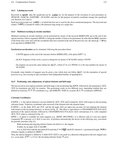
4.6 Complementary Features 133U@©@y4.6.3 Labeling keywordsKeywords in zgoubi data file zgoubi.dat can ¨¦´¡W¢¨ be ’ed, for the purpose of the execution of such procedures asPICKUPS, FAISCNL, FAISTORE , SCALING, and also for the purpose of particle coordinate storage into zgoubi.plt(see Sections 4.6.2 and 2).Each keyword accepts ¨¦´¡W¢¨ two ’s, of which the first one is used for the above mentioned purposes. The keyword and¨´ ¨ related [’s] should fit within a 80-character long string on a single line.¡.¢4.6.4 Multiturn tracking in circular machinesMultiturn tracking in circular machines can be performed by means of the keyword REBELOTE, put at the end of theoptical structure with its argument NPASS q being the number of turns to be performed. In order that the IMAX particlesof the beam start a new turn with the coordinates they have reached at the end of the previous one, the option Ñ §£§hasto be specified in REBELOTE.Synchrotron acceleration can be simulated, following the procedure below- CAVITE appears at the end of the structure (before REBELOTE), with option IOPT q- the R.F. frequency of the cavity is given a timing law by means of SCALING, family CAVITE- the magnets are given the same timing law ¡., SCALING., (whereq to NPASS q is the turn number) by means ofEventually some families of magnets may be given a law which does not follow ¡., , for the simulation of specialprocesses (e.g. fast crossing of spin resonances with independent families of quadrupoles).4.6.5 Positioning, (mis-)alignement, of optical elements and field mapsThe last record in most optical elements and field maps is the positioning flag KPOS, followed by the parameterss XCE,YCE for translation and ALE for rotation. The positioning works in two different ways, depending whether they aredefined in Cartesian§#"$Œ"[ coordinates (e.g., QUADRUPO, TOSCA), or polar ( 1 , Å , ) coordinates (DIPOLE).Cartesian Coordinates:If KPOS q , the optical element is moved (shifted by XCE, YCE and Z-rotated by ALE) with respect to the incomingreference frame. Trajectory coordinates after traversal of the element refer the element frame.If KPOS , the shifts XCE and YCE, and the tilt angle ALE are taken into account, for mis-aligning the elementwith respect to the incoming reference, as shown in Fig. 42. The effect is equivalent to a CHANGREF(XCE,YCE,ALE)upstream of the optical element, followed by CHANGREF(XCS,YCS,ALS=-ALE) downstream of it, with computedXCS, YCS values as schemed in Fig. 42.KPOS option is available for some magnets (e.g., BEND, MULTIPOL); it is effective only if a non zero dipolecomponent ¡ q is present, or if ALE is non-zero. It positions automatically the device in the following way, convenientfor periodic structures (Fig 43).Both incoming and outgoing refernce frames are tilted w.r.t. the magnet0,either, by an angle ALE ifALEor, if ALE=0 by half the ‡deviation (such that ¨ @ y ¢ŸµH¢ 7 (*)-Å( @ wherein L = geometrical length, =¡ ! 1 ! @ Ŧ reference rigidity as defined in OBJET).Next, the optical element is shifted by Y-shift=YCE (XCE is not used) in a direction orthogonal to the new magnet axis(i.e., at an ´v¨ angle wrt. the incoming reference § frame -axis).¢