Electrohydraulic Valves - Moog Inc
Electrohydraulic Valves - Moog Inc
Electrohydraulic Valves - Moog Inc
- No tags were found...

You also want an ePaper? Increase the reach of your titles
YUMPU automatically turns print PDFs into web optimized ePapers that Google loves.
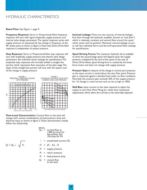
HYDRAULIC CHARACTERISTICSRated Flow: See Figure 1. page 9.Frequency Response: Servo or Proportional Valve frequencyresponse will vary with signal amplitude, supply pressure, andinternal valve design parameters.The typical response varies withsupply pressure as expressed by the change in frequency of the90˚ phase point, as shown in figure 2. Note that Direct Drive Valveresponse is independent of system pressure.Step Response: Servo or Proportional Valve step response willvary with amplitude, supply pressure and internal valve designparameters. See individual series catalogs for specifications. Fullamplitude step responses will normally exhibit a straight lineportion which represents flow saturation of the pilot stage.Theslope of this straight line portion will vary with the square rootof the change in supply pressure.1.51.41.31.21.11.0FpFref 0.90.80.70.60.50.4FIGURE 2FREQUENCY RESPONSE CHANGEWITH PRESSUREFp natural frequency at other pressures=Fref natural frequency at 3,000 psi (210 bar)0.30 1000 2000 3000 04000 5000LINEAR SCALE SUPPLY PRESSURE (PSI)FIGURE 3CHANGE IN CONTROL FLOW WITHCURRENT AND LOAD PRESSURECONTROL FLOW–% RATED FLOW-100 -80 -60 -40 -2025%50%75%10080604020-20-40-60-80100% INPUT CURRENT75%50%25%-20 -40 -60 -80 -100100%-100LOAD PRESSURE DROP–% SUPPLY PRESSUREInternal Leakage: There are two sources of internal leakage;first, flow through the hydraulic amplifier (known as “tare flow”)which is relatively constant, and second, flow around the spoolwhich varies with its position. Maximum internal leakage occursat null. See individual Servo and Servo-Proportional Valve catalogsfor specifications.Spool Driving Forces: The maximum hydraulic force availableto drive the second-stage spool will depend upon the supplypressure, multiplied by the end of the spool. In the case ofDirect Drive <strong>Valves</strong>, spool driving force is created by the linearforce motor and does not change with supply pressure.Pressure Gain: A measure of the change in control port pressuresas the input current is varied about the zero flow point. Pressuregain is measured against a blocked load under no flow conditions.Normally the pressure gain exceeds 30% of the supply pressurefor 1% change in rated current and can be as high as 100%.Null Bias: Input current to the valve required to adjust theoutput to zero flow. Most <strong>Moog</strong> <strong>Inc</strong>. valves have mechanicaladjustments which allow the null bias to be externally adjusted.Flow–Load Characteristics: Control flow to the load willchange with various combinations of load pressure drop andelectrical input, as shown in figure 3.These characteristics closelyfollow the relationship.QL = QNL iPVwhere:QNL = no-load flow at1,000 psi drop forServovalves and150 drop for P.V.i = actual/rated current (%)PV = (PS– PR) – PLPS = supply pressurePR = return pressurePL = load pressure dropQL = control flowto the load10