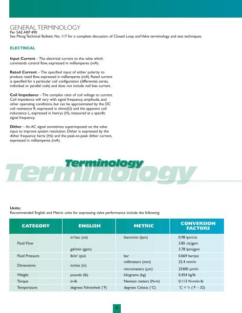
GENERAL TERMINOLOGYPer SAE ARP 490See <strong>Moog</strong> Technical Bulletin No. 117 for a complete discussion of Closed Loop and Valve terminology and test techniques.ELECTRICALInput Current – The electrical current to the valve whichcommands control flow, expressed in milliamperes (mA).Rated Current – The specified input of either polarity toproduce rated flow, expressed in milliamperes (mA). Rated currentis specified for a particular coil configuration (differential, series,individual or parallel coils) and does not include null bias current.Coil Impedance – The complex ratio of coil voltage to current.Coil impedance will vary with signal frequency, amplitude, andother operating conditions, but can be approximated by the DCcoil resistance R, expressed in ohms(½) and the apparent coilinductance L, expressed in henrys (H), measured at a specificsignal frequency.Dither – An AC signal sometimes superimposed on the valveinput to improve system resolution. Dither is expressed by thedither frequency hertz (Hz) and the peak-to-peak dither current,expressed in milliamperes (mA).TerminologyTerminologyUnits:Recommended English and Metric units for expressing valve performance include the following:CATEGORY ENGLISH METRICCONVERSIONFACTORSin 3 /sec (cis) liters/min (lpm) 0.98 lpm/cisFluid Flow3.85 cis/gpmgal/min (gpm)3.78 lpm/gpmFluid Pressure lb/in 2 (psi) bar 0.069 bar/psiDimensionsinches (in)millimeters (mm)25.4 mm/inmicrometers (µm)25400 µm/inWeight pounds (lb) kilograms (kg) 0.454 kg/lbTorque in-lb Newton meters (N-m) 0.113 N-m/in-lbTemperature degrees Fahrenheit (˚F) degrees Celsius (˚C) ˚C = 5 /9 (˚F – 32)8
HYDRAULICControl Flow QV – The flow through the valve control ports tothe load expressed in in 3 /sec (cis), gal/min (gpm), or liters/min (lpm).Rated Flow QR – Servovalves are typically rated at 1,000 psidrop, while Proportional <strong>Valves</strong> are rated at 150 psi drop.Theflow under no-load condition, QNL, will vary with supply pressureas shown in Figure 1.The relationship can be calculated by:QNL = QRPSÆPwhere:QNL = no-load flowPS = supply pressureQR = Servovalve rated flowat 1,000 psi drop, P.V.rated flow at 150 psi dropÆP =valve drop, typically 1,000 psifor Servovalves and 150 psifor Proportional <strong>Valves</strong>Valve Pressure Drop ÆPV – The sum of the differentialpressure across the control orifices of the valve spool, expressedin psi or bar.Valve pressure drop will equal the supply pressure,minus the return pressure, minus the load pressure drop,[ÆPV = (PS – R) – ÆPL].PERFORMANCELinearity – The maximum deviation from control flow from thebest straight line of flow gain, expressed as percent of rated current.Symmetry – The degree of equality between the flow gain of onepolarity and that of reversed polarity. Measured as the differencein flow gain for each polarity, expressed as percent of the greater.Hysteresis – The difference in valve input currents requiredto produce the same valve output as the valve is slowly cycledbetween plus and minus rated current.2001005040302010510.5FIGURE 1CHANGE IN RATED FLOW WITH PRESSURE60 gpm @ 1000 PSID40 gpm @ 1000 PSID30 gpm @ 1000 PSID25 gpm @ 1000 PSID20 gpm @ 1000 PSID15 gpm @ 1000 PSID10 gpm @ 1000 PSID5.0 gpm @ 1000 PSID2.5 gpm @ 1000 PSID1.0 gpm @ 1000 PSIDThreshold – The increment of input current required to producea change in valve output.Valve threshold is usually measured as thecurrent increment required to change from an increasing output toa decreasing output, expressed as percent of rated current.Lap – In a sliding spool valve, the relative axial position relationshipbetween the fixed and moveable flow-metering edges withinthe null region. Lap is measured as the total separation at zeroflow of straight line extensions of nearly straight portions ofthe flow curve.Pressure Gain – The change of load pressure drop with changeof input current at zero control flow (control ports blocked),expressed as nominal psi/mA or bar/mA throughout the rangeof load pressure between ±40% supply pressure.Null – The condition where the valve supplies zero control flowat zero load pressure drop.0.1100 200 500 1000 2000 3000 5000Flow Gain – The normal relationship of control flow to inputcurrent, expressed as cis/mA, gpm/mA, or lpm/mA.No Load Flow – The control flow with zero load pressure drop,expressed in cis, gpm, or lpm.Internal Leakage – The total internal valve flow from pressure to returnwith zero control flow (usually measured with control ports blocked),expressed in cis, gpm, or lpm. Leakage flow will vary with input current,generally being a maximum at the zero level of null (called null leakage).Null Bias – The input current required to bring the valve to null,excluding the effects of valve hysteresis, expressed as percent ofrated current.Null Shift – The change in null bias resulting from changes inoperating conditions or environment, expressed as percent ofrated current.Frequency Response – The relationship of no-load control flowto input current when the current is made to vary sinusoidally atconstant amplitude over a range of frequencies. Frequency responseis expressed by the amplitude ratio in decibels (db) and phaseangle in degrees (˚) over a specific frequency range.Load Pressure Drop ÆPL – The differential pressure betweenthe control ports (that is, across the load actuator), expressed inlbs/in 2 (psi) or bar.9