Model F446 Deluge Valve - Wormald New Zealand
Model F446 Deluge Valve - Wormald New Zealand
Model F446 Deluge Valve - Wormald New Zealand
- No tags were found...

Create successful ePaper yourself
Turn your PDF publications into a flip-book with our unique Google optimized e-Paper software.
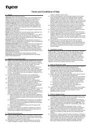
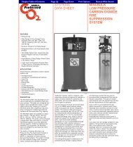
II *M(2:q0mm)1 8-l/4”(209,6mm)SOLENOID VALVE(FOR ELECTRICACTUATION)\l/2” NPT,DIAPHRAGM%YIFRl-l/4”DRAINNPT/l-l/4”/ DRAINNPT.Left View* MINIMUM CLEARANCE, ADDITIONAL 2” (50 mm) RECOMMENDEDFIGURE DNOMINAL INSTALLATION DIMENSIONS FORELECTRIC ACTUATION TRIMFront Viewbe installed with smooth bends thatwill not restrict flow.5. The main drain and drip funnel drainmay be interconnected provided acheck valve is located at least 12inches (300mm) below the drip funnel.6. Suitable provision must be made fordisposal of drain water. Drainagewater must be directed such that itwill not cause accidental damage toproperty or danger to persons.7. Connect the Diaphragm ChamberSupply Control <strong>Valve</strong> to the inlet sideof the system’s main control valve inorder to facilitate setting of the <strong>F446</strong>.8. Unused pressure alarm switch connectionsmust be plugged.9. Conduit and electrical connectionsare to be made in accordance withthe requirements of the authorityhaving jurisdiction and/or the NationalElectric Code.-4-Steps 1 through 11 are to be performedwhen initially setting the <strong>F446</strong> <strong>Valve</strong>;after an operational test of the firesprinkler system; or, after system operationdue to a fire.1. Close the Diaphragm Chamber SupplyControl <strong>Valve</strong>.2. Close the Main Control <strong>Valve</strong>.3. Open the Main Drain <strong>Valve</strong> and allauxiliary drains in the system. Closethe auxiliary drain valves after waterceases to discharge. Leave the MainDrain <strong>Valve</strong> open.4. Depress the plunger of the AutomaticDrain <strong>Valve</strong> to verify that it isopen and that the <strong>F446</strong> <strong>Valve</strong> iscompletely drained.
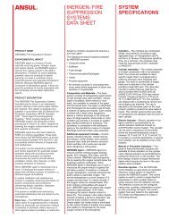
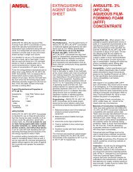
T\SYSTEM PIPING WITH OPEN NOZZLES OR SPRINKLERS-NORMALLY DRY,________________--_____________________-------------.ELECTRIC DETECTION SYSTEM(TYPICALLY 24 VOLTS DCIHEAT DETECTORS, SMOKE DETECTORS,MANUAL PULL STATIONS, ETC.POWER SUPPLY(TYPICALLY120 VOLTS AC)I -DRAIN 1 MAIN DRAIN ‘)fl 7DRAIN‘No”;;;:” 1 ! 1MAIN CONTROL \/ALVE(NORMALLY OP EN)DIAPHRAGM CHAMBER SUPPLY CONNECTIONWATERSUPPLYFIGURE EDELUGE VALVE SYSTEM SCHEMATIC- ELECTRIC ACTUATION-5. Clean the Strainer in the DiaphragmChamber Supply connection by removingthe clean-out plug andstrainer basket. The Strainer may beflushed out by momentarily openingthe Diaphragm Chamber SupplyControl <strong>Valve</strong>.6. Reset the actuation system.Manual Actuation - Push the operatinglever up; however, do not closethe hinged cover at this time.Electric Actuation - Reset the electricdetection system in accordancewith the manufacturer’s instructionsto de-energize the solenoid valve.7. Open the Diaphragm Chamber SupplyControl <strong>Valve</strong> and allow time forfull pressure to build up in the DiaphragmChamber.8. Operate (open) the Manual ControlStation to vent trapped air from theDiaphragm Chamber. If necessary,first open the hinged cover, and thenfully pull down on the operatinglever. SLOWLY close the operatinglever, by pushing it up, after aeratedwater ceases to discharge from theManual Control Station drain tubing.Close the hinged cover and insert anew break rod in the small holethrough the top of the enclosing box.9. Inspect drain connections from theManual Control Station and Solenoid<strong>Valve</strong>. Any leaks must be correctedbefore proceeding to the nextstep.10. Slowly open the Main Control <strong>Valve</strong>.Close the Main Drain <strong>Valve</strong> as soonas water discharges from the drainconnection. Observe the AutomaticDrain <strong>Valve</strong> for leaks. If there areleaks, determine/correct the causeof the leakage problem. If there areno leaks, the <strong>F446</strong> <strong>Valve</strong> is ready tobe placed in service and the MainControl Vave must then be fullyopened.11. Open the Alarm Control <strong>Valve</strong>.It is recomended that the Alarm Control<strong>Valve</strong> be wired sealed in theopen position with a No. 16 twistedwire, the ends of which are securedby a lead seal. The wire seal shouldbe looped through the hole in thehandle and tightly twisted around thepipe nipple at the outlet of the AlarmControl <strong>Valve</strong>.NOTEAfter setting a fire protection system,notify the proper authorities and advisethose responsible for monitoringproprietary andlor central stationalarms.
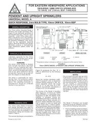
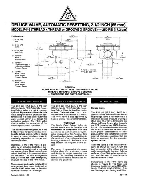
ElE2E3TO DRIP FUNNELPRESSURE ALARM (”SWITCH-‘y,’,‘..s-‘:26 20314” NPT CONNECTION27 FOR WATER MOTORALARM/FIGURE FVALVE TRIM ASSEMBLY-6-
of the leakage problem. If there areno leaks, the <strong>F446</strong> <strong>Valve</strong> is ready tobe placed in service and the MainControl Vave must then be fullyopened.Quarterly Waterflow Alarm Test ProcedureTesting of the the system waterflowalarms should be performed quarterly.To test the waterflow alarm, open theAlarm Test <strong>Valve</strong>, which will allow aflow of water to the Pressure AlarmSwitch and/or Water Motor Alarm.Upon satisfactory completion of thetest, close the Alarm Test <strong>Valve</strong>.Seller warrants for a period of one yearfrom the date of shipment (warrantyperiod) that the products furnishedhereunder will be free from defects inmaterial and workmanship.For further details on Warranty seePrice List.All orders for <strong>Model</strong> <strong>F446</strong> <strong>Valve</strong>s, trim,accessories, and replacement partsmust include the description and ProductSymbol Number (PSN).<strong>Valve</strong>s:Specify: 250 psi (17,2 bar), 2-l /2 inch,(specify Thread x Thread or Groove xGroove), <strong>Model</strong> <strong>F446</strong> Automatic Resetting<strong>Deluge</strong> <strong>Valve</strong>, PSN (specify).Thread x ThreadPSN 52-446-l-001Groove x Groove PSN 52-446-l -002“Standard Order” Black Trim:Specify: Black Electric Actuation Trimfor use with the <strong>Model</strong> <strong>F446</strong> AutomaticResetting <strong>Deluge</strong> <strong>Valve</strong>,PSN 52-446-l-103.“Special Order” GalvanizedTrim:Specify: Galvanized Electric ActuationTrim for use with the <strong>Model</strong> <strong>F446</strong> AutomaticResetting <strong>Deluge</strong> <strong>Valve</strong>,PSN 52-446-2-l 03.ReplacementTrim Parts (Fig. F):Specify: (description) for use with<strong>Model</strong> F445 Automatic Resetting <strong>Deluge</strong><strong>Valve</strong>, PSN (specify).1 - 600 lb. WaterPressureGauge2 - l/4” Gauge Test<strong>Valve</strong>3 - FIB0 ManualControl Station4 - l-1 /4” Angle<strong>Valve</strong>5 - 112” Ball <strong>Valve</strong>6 - 112’ SwingCheck <strong>Valve</strong>7 - l/2” SpringLoaded Check<strong>Valve</strong>8 - Priming SupplyRestriction9 - l/2” Y-StrainerIO - F793 AutomaticDrain<strong>Valve</strong>11 - Drip Funnelsupport Plug12 - Drip Funnelsupport13-DripFunnel ____14 - 3/32’ VentFittingPSN 92-343-l -004PSN 46-005-l -002PSN 52-289-l-001PSN 46-046-I -007PSN 46-050-I -004PSN 46-062-l -004PSN 92-322-l -002PSN 92-020-I -009PSN 52-353-l-005PSN 52-793-l -004PSN 92-21 I-l -005PSN 92-211-l-003PSN 92-343-l -007PSN 92-032-I -002E5 - 24VDC Solenoid<strong>Valve</strong> PSN 52-287-l -124Accessories:Refer to the following Technical DataSheet (TD).Pressure Alarm SwitchReplacementTD213<strong>Valve</strong> Parts (Fig. B):Specify: (description) for use with<strong>Model</strong> <strong>F446</strong> Automatic Resetting <strong>Deluge</strong><strong>Valve</strong>, PSN (specify).The following are the nominal weightsfor the valves and trim:2-l/2” Thread x Thread<strong>Model</strong> <strong>F446</strong> <strong>Deluge</strong> <strong>Valve</strong>2-l/2” Groove x Groove<strong>Model</strong> <strong>F446</strong> <strong>Deluge</strong> <strong>Valve</strong>Electric Actuation TrimWith 24VDC Solenoid <strong>Valve</strong>41 Ibs. (18,6 kg)44 Ibs. (20,O kg)27 Ibs. (12,2 kg)2 - Cover..3 - Diaphragm4 - Diaphragm Ring5 - Cap Screw,l/4”-20 UNCx 314”6 - Cap Screw,l/2”-13 UNCx 710”7 - Center <strong>Valve</strong>8-Facing _........10 - Facing Retainer11 - Retainer ScrewPSN 92-446-l -002PSN 92-445-l -003PSN 92-445-l -004PSN 62-634-I-104PSN 62-634-l -111PSN 92-445-i -005PSN 92-445-l -006PSN 92-445-l -008PSN 62-679-l -012@I Reg. trademark of GRINNELL CORPORATION, 3 TYCO PARK, EXETER, NH 03833 A tl/CO INTERNATIONAL LTD. COMPANY