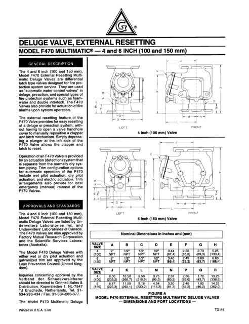
Model F470 Deluge Valve - Wormald New Zealand
Model F470 Deluge Valve - Wormald New Zealand
Model F470 Deluge Valve - Wormald New Zealand
- No tags were found...

You also want an ePaper? Increase the reach of your titles
YUMPU automatically turns print PDFs into web optimized ePapers that Google loves.
90 (27.43)80 (24.38)3z 70 (21,34)iiikkiLc‘380 (18,29)50 (15,24)? 40 (12,19)5: 30 (9.14)sE420 (8,lO)0(12:) 6 4 1 & 100 120 140 180 175(83) (8t3) (%7) (11,O) (12,l)NOTE: IF THE SUPPLY PRESSURE IS VARIABLE, SUPPLY PRESSURE, PSI (BAR)ASSUME MINIMUM EXPECTED VALUE.GRAPH BWET PILOT LINE DESIGN CRITERIAWet Pilot Actuation(Figure F-l, Items 1 through 35)The Wet Pilot Actuation Trim providesfor connection of a detection systemconsisting of wet pilot sprinklers (heatdetectors) and manual control stationsinterconnected with minimum l/2 inch(15 mm) Schedule 40 steel pipe. Thepilot line is connected to the “Wet PilotDetection” connection shown in FigureF-l. Nominal installation dimensionsfor the Wet Pilot Actuation Trim areshown in Figure D.WiTERSUPPLY-iRESSUREGRAPH CDRY PILOT LINE PRESSUREproval of the <strong>F470</strong> <strong>Valve</strong>s and are necessaryfortheir proper operation. Each;rmage of trim includes the followingREQUIREMENTS• Alarm Control <strong>Valve</strong>• Automatic Drain <strong>Valve</strong>• Dry Pilot Line Pressure Gauge(as applicable)• Water Supply Pressure Gauge To ease field assembly of the trim ar-• Diaphragm Chamber rangements, the appropriate compo-Pressure Gaugenents required for Wet Pilot Actuation,• Diaphragm Chamber Connections Dry Pilot Actuation, or Electric• Actuation Devices (as applicable) Actuaton are factory assembled as• Main Drain <strong>Valve</strong> shown in Figure F-2.• Atarm Test <strong>Valve</strong>Wet pilot sprinklers are to be minimuml/2 inch (15 mm) orifice listed or approvedautomatic sprinklers. ManualControl Stations are to be either the<strong>Model</strong> F180 or F184 described in TechnicalData Sheet TD121.The maximum height of a wet pilot lineabove the <strong>F470</strong> <strong>Valve</strong> must not exceedthe limitations given in Graph B as afunction of the minimum water supplypressure to the <strong>F470</strong> <strong>Valve</strong> and thelength of the pilot line to the most remotepilot sprinkler.Provision must be made for installinga l/2 inch (15mm) orifice, Inspector’sTest Connection at the most hydraulicallydemanding location of a wet pilotline (usually adjacent to the highestand most remote wet pilot sprinkler ormanual control station).-4-
To determine the most hydraulicallydemanding location of a wet pilot line,when the choice between two or morelocations is not readily apparent, determinefor each location the elevationabove the <strong>F470</strong> <strong>Valve</strong> and the equivalentlength of fittings plus horizontalpipe from the <strong>F470</strong> <strong>Valve</strong> to the location.Then, using Graph B, determinethe minimum system supply pressurerequired for the elevation and equivalentlength of pipe at each location.Interpolate between the equivalentlength plots as necessary. The locationrequiring the highest system supplypressure is the most hydraulically demandinglocation for the wet pilot line.(Reference: In no case should the requiredsystem supply pressure exceedthe actual available minimum expectedsystem supply pressure.)Operation of a pilot sprinkler or openingof a manual control station resultsin a rapid pressure drop in the DiaphragmChamber of the <strong>F470</strong> <strong>Valve</strong>,and the force differential appliedthrough the Clapper Latch which holdsthe Clapper down in the set position isreduced to below the valve trip point.NOTESWet Pilot Lines must be maintained ata minmum temperature of 40%/4”C.It is recommended that internally galvanizedpipe and cast iron fittings beused for wet pilot lines.Dry Pilot Actuation(Figure F-l, Items 1 through 35 plusItems Dl through D14)The Dry Pilot Actuation Trim providesfor installation of a detection systemconsisting of dry pilot sprinklers (heatdetectors) and manual control stationsinterconnected with minimum l/2 inch(15 mm) steel pipe. The pilot line,which is to be oressurized with air ornitrogen, is connected to the “Dry PilotDetection” connection shown in FiaureF. Provision must be made for a”l/2inch (15 mm) orifice, Inspector’s TestConnection at the most remote locationfrom the <strong>F470</strong> <strong>Valve</strong>. Nominal installationdimensions for Dry Pilot ActuationTrim are shown in Figure E.The Dry Pilot Actuation Trim is providedwith a listed and approved <strong>Model</strong>B-l Dry Pilot Actuator, which is describedin Technical Data SheetTDll7W. The Actuator is rated for useat a maximum pilot service pressure of50 psi (3,4 bar) and a maximum watersupply service pressure of 175 psi(12,l bar).Operation of a pilot sprinkler or openingof a manual control station, releasespneumatic pressure from thepilot line. In turn, the Dry Pilot Actuatoropens resulting in a rapid pressuredrop in the Diaphragm Chamber of the<strong>F470</strong> <strong>Valve</strong>, and the force differentialapplied through the Clapper Latchwhich holds the Clapper down in theset position is reduced to below thevalve trip point.Dry pilot sprinklers are to be minimuml/2 inch (15 mm) orifice listed or approvedautomatic sprinklers. ManualControl Stations are to be either the<strong>Model</strong> Fl80 or F184 described in TechnicalData Sheet TDl21.Graph C shows the “minimum pilot lineservice pressure” as a function of thewater supply pressure. The pressurein the dry pilot actuation system mustbe automatically maintained using oneof the following maintenance devices,as appropriate.• <strong>Model</strong> F324 Air Maintenance Device(pressure reducing type),refer to Technical Data SheetTDlll.• <strong>Model</strong> F326 Air Maintenance Device(compressor control type),refer to Technical Data SheetTDl12.• <strong>Model</strong> F328 Nitrogen MaintenanceDevice (high pressure reducingtype), refer to TechnicalData Sheet TDl13.NOTESThe dewpoint of the pilot line airpressuremust be maintained below thelowest ambient temperature to whichthe dry pilot actuation system will beexposed. Accumulation of water in thepilot line connection to the Actuatorwill lower the air pressure at whichthe Actuator will open and possiblyprevent proper operation. Also, introductionof moisture into the pilot linesexposed to freezing temperatures cancreate an ice buildup which couldpreventproper operation of the ActuatorAn air dryer must be installed wherethe moisture content of the air supplyis not properly controlled at less thanthe required value. The desiccantdryer with mounting accessories describedin Technical Data SheetTD135 is suitable for use with a maximuminlet pressure of 150 psi (lo,3bar) and for drying system air downto a dewpoint of less than -2O”Fl-29°Cat a pressure of 45 psi (3,l bar) .It is recommended that an F328 NitrogenMaintenance Device be utilizedin dry pilot actuation system applicationswhere the dewpoint must bemaintained below -2O”Fl-29°C. SeeTechnical Data Sheet TD113.It is recommended that internallygalvanizedpipe and cast iron fittings beused for dry pilot lines.Supervision of the pressure in the drypilot actuation system and/or alarm-5-which separately indicates operationof the detection system is recommendedand may be required by theauthority having jurisdiction. A dualsetting low pressure alarm switch,such as the unit described in TechnicalData Sheet TD210, is suitable for theservice. The recommended pressuresettings are as follows:. Low pressure alarm setting atapproximately 6 psi (0,4 bar)below the minimum pilot lineservice pressure requirementshown in Graph C.. Fire alarm setting at approximately15 psi (1 ,O bar) belowthe minimum pilot line servicepressure requirement shownin Graph C.The Pressure Relief <strong>Valve</strong> (Ref. ItemD5 - Fig. F-l) is factory set to relieveat a pressure of approximately 45 psi(3,1 bar); however, it may be field adjustedto a lower pressure, if required.Electric Actuation Trim(Figure F-l, Items 1 through 35 plusItems El through E5)The Electric Actuation Trim is requiredfor electric operation of the <strong>F470</strong> <strong>Valve</strong>by a detection system consisting ofelectrical devices such as heat sensitivethermostats, smoke detectors,and/or electric manual pull stations.Information on the various types of Solenoid<strong>Valve</strong>s that may be used withthis trim package is given in TechnicalData Sheet TDll9. A listed and approved,24VDC Solenoid <strong>Valve</strong> fornon-hazardous locations is suppliedas standard. Nominal installation dimensionsfor the Electric ActuationTrim are shown in Figure D.NOTEApproval by Factory Mutual is contingenton the use of an FM Approved24VDC Solenoid <strong>Valve</strong>. FM only approvessolenoid valves for use in nonhazardouslocations.The Electric Actuation Trim is only tobe used in conjunction with an electricdeluge valve releasing panel (automaticcontrol unit) that is listed or approved(as appropriate) for fire protectionsystem releasing service. Inaddition, the deluge valve releasingpanel is only to be operated by listedor approved (as approriate) fire detectors.Operation of an electrical device suchas a heat sensitive thermostat, smokedetector, or electrical manual controlstation signals the deluge valve releasingpanel to energize the Solenoid<strong>Valve</strong>. In turn, the energized Solenoid<strong>Valve</strong> opens resulting in a rapid pressuredrop in the Diaphragm Chamberof the <strong>F470</strong> <strong>Valve</strong>, and the force differ-
ential applied through the ClapperLatch which holds the Clapper down inthe set position is reduced to below thevalve trip point.NOTEConsult with the Authority HavingJurisdiction regarding installationcriteria pertaining to electric actuationcircuitry.TOSYSTEMThe <strong>Model</strong> <strong>F470</strong> Multimatic <strong>Deluge</strong><strong>Valve</strong> is a differential latch type valvewhich depends upon water pressure inthe Diaphragm Chamber (Ref. FigureC-l) to hold the Clapper closedagainst the water supply pressure. Thenominal trip ratio is 2.5 to 1, i.e., the<strong>F470</strong> <strong>Valve</strong> operates (opens) when thepressure in the Diaphragm Chamber isreduced to approximately 40 percentof the water supply pressure.WATER- Set Position -Figure C-lTOSUPPLYSYSTEMWhen the <strong>F470</strong> <strong>Valve</strong> is set for service,the Diaphragm Chamber is pressurizedthrough the trim connections fromthe inlet side of the system’s main controlvalve, for example an O.S.&Y. gatevalve or butterfly valve (Ref. FigureG-l, G-2, or G-3). Opening of an actuationdevice, for example the solenoidvalve in the Electric Actuation Trim(Ref. Fig. G-3), releases water fromthe Diaphragm Chamber faster than itcan be replenished through the l/8inch (3,2mm) Restriction in the DiaphragmChamber Supply Connection.This results in a rapid pressure drop inthe Diaphragm Chamber and the forcedifferential applied through the ClapperLatch to hold the Clapper down inthe set position is reduced to below thevalve trip point. The water supply pressurethen forces the Clapper open permittingwater to flow into the systempiping, as well as through the AlarmPort to actuate the system alarms (Ref.Figure C-2).ALARMPORTWATER‘SUPPLY- Open Position (Flowing)-Figure C-2TOSYSTEMIIUPzz’When the system main control valve isclosed to stop waterflow into the system,the Clapper will be preventedfrom resetting by the Clapper Latchuntil the Rest Knob is pushed inward(Ref. Figure C-3). Pushing the ResetKnob inward will temporarily repositionthe Clapper Latch away from the waterwayand allows the Clapper to dropinto the seated position.WATER‘SUPPLY- Open Position (No Flow)-Figure C-3FIGURE CMODEL <strong>F470</strong> EXTERNAL RESETTING MULTIMATIC DELUGE VALVE- SET AND OPEN POSITIONS --6-
SOLENOID VALVE(FOR ELECTRICDIAPHRAGMCHAMBER SUPPLYLeft ViewFront ViewNominal Installation Dimensionsin Inches and (MM)B C D E F G H J K8.69 14.25 13.69 19.00(220,7) (362,0) (347,7) (462,6) (15&‘) (l%;) (~~~) (lk$, (%?5)6.69 15.12 14.50 20.00 5.50 7.62 8.88 8.56 6.31(220,7) (384,0) (368,3) (508,O) (139,7) (193,5) (225,6) (217,4) (160,3)FIGURE DNOMINAL INSTALLATION DIMENSIONS FORWET PILOT ACTUATION TRIM OR ELECTRIC ACTUATION TRIM* MINIMUM CLEARANCE,ADDITIONAL2’ (50mm) RECOMMENDEDNOTESProper operation of the <strong>Model</strong> <strong>F470</strong>Multimatic <strong>Deluge</strong> <strong>Valve</strong>s dependsupon their trim being installed in accordancewith the instructions givenin this Technical Data Sheet. Failureto follow the appropriate trim diagrammay prevent the <strong>F470</strong> <strong>Valve</strong>from fintioning properly, as well asvoid listings, approvals, and themanufacturer$ warranties.The <strong>F470</strong> <strong>Valve</strong> must be installed in areadily visable and accessible location.The <strong>F470</strong> <strong>Valve</strong>, associated trim, andwet pilot lines must be maintained ata minimum temperature of 4O”F/4”C.Heat tracing of the <strong>F470</strong> <strong>Valve</strong> or itsassociated trim is not permitted. Heattracing can result in the formation ofhardened mineral deposits which arecapable of preventing proper operation.The <strong>Model</strong> <strong>F470</strong> Multimatic <strong>Deluge</strong><strong>Valve</strong> is to be installed in accordancewith the following criteria:1 a. Flange mounting fasteners are to betightened uniformly using a crossdrawsequence. Fastener specificationsare to be as required by theauthority having jurisdiction. Tighteningtorques are to be as indicatedbelow.<strong>Valve</strong> Fastener TorqueSize Size Ft. Lbs. (Nm)4” 5/8” (M16) 40-50 (54-68)6” 314” (M20) 50-65 (68-81)lb. All nipples, fittings, and devicesmust be clean and free of scale andburrs before installation. Use pipe-7-thread sealant sparingly on malepipe threads only.NOTEIt is recommended that internallygalvanized pipe and cast iron fittingsbe used for wet or dry pilotlines.2. The <strong>F470</strong> <strong>Valve</strong> must be trimmed inaccordance with Figures F-l & F-2.3. Care must be taken to make surethat check valves, strainers, globevalves, etc. are installed with theflow arrows in the proper direction.4. Drain tubing to the drip funnel mustbe installed with smooth bends thatwill not restrict flow.5. The main drain and drip funnel drainmay be interconnected provided acheck valve is located at least 12
-B-I112” NPT AIR SUPPLY’ (FROM AbTOMATlCAIR/NITROGENMAINTENANCE DEVICE), DRY PILOTACTUATOR2” NPT.DRAINDIAPHRAGMCHAMBER SUPPLLeft ViewNominal Installation DimensionsFront Viewin Inches and (MM)* MINIMUM CLEARANCE, ADDITIONAL 2’ (50mm) RECOMMENDEDFIGURE ENOMINAL INSTALLATION DIMENSIONS FORDRY PILOT ACTUATION TRIMinches (300 mm) below the drip funnel.6. Suitable provision must be made fordisposal of drain water. Drainagewater must be directed such that itwill not cause accidental damage toproperty or danger to persons.7. Connect the Diaphragm ChamberSupply Control <strong>Valve</strong> to the inlet sideof the system’s main control valve inorder to facilitate setting of the <strong>F470</strong><strong>Valve</strong> (Ref. G-l, G-2, or G-3).8. An Inspector’s Test Connection, asdescribed in the Technical Data section,must be provided for Wet or DryPilot Actuation systems.9. An Air Maintenance Device, as describedin the Technical Data Section,must be provided for Dry PilotActuation.10. Adesiccant dryer, when specified forDry Pilot Actuation, is to be installedbetween a drip leg and the Air MaintenanceDevice.-8-11. The Low Pressure Alarm Switch forDry Pilot Actuation is to be adjustedas follows:. Low pressure alarm setting atapproximately 6 psi (0,4 bar)below the minimum pilot lineservice pressure requirementshown in Graph C.. Fire alarm setting at approximately15 psi (1 ,O bar) belowthe minimum pilot line servicepressure requirement shownin Graph C.
12. Unused pressure alam switch connectionsmust be plugged.13. The Pressure Relief <strong>Valve</strong> providedwith the Dry Pilot Actuation Trim isfactory set to relieve at a pressure ofapproximately 45 psi (3,1 bar),which can typically be used for amaximum normal dry pilot actuationsystem pressure of 40 psi (2,8 bar).The Pressure Relief <strong>Valve</strong> mav bereset; however, it must be be rksetto relieve at a pressure which is inaccordance with the requirements ofthe authority havng jurisdiction.To reset the Pressure Relief <strong>Valve</strong>,first loosen the jam nut and thenadjust the cap accordingly - clockwisefor a higher pressure setting orcounterclockwise for a lower pressuresetting. After verifying the desiredpressure setting, tighten thejam nut.14. Conduit and electrical connectionsare to be made in accordance withthe requirements of the authorityhaving jurisdiction and/or the NationalElectric Code.Steps 1 through 12 are to be performedwhen initially setting the <strong>Model</strong><strong>F470</strong> Multimatic <strong>Deluge</strong> <strong>Valve</strong>; after anoperational test of the fire protectionsystem; or, after system operation dueto a fire.1. Close the Diaphragm ChamberSupplyControl <strong>Valve</strong>.2. Close the Main Control <strong>Valve</strong>, and ifthe system is equipped with Dry PilotActuation, close the Air Supply Control<strong>Valve</strong> (Ref. Figure F-l).3. Open the Main Drain <strong>Valve</strong> and allauxiliary drains in the system. Closethe auxiliary drain valves after waterceases to discharge. Leave the MainDrain <strong>Valve</strong> open.4. Depress the plunger of the AutomaticDrain <strong>Valve</strong> to verify that it isopen and that the <strong>F470</strong> <strong>Valve</strong> iscompletely drained.5. Push the Reset Knob inward to allowthe Clapper to reseat.Under normal circumstances, the reseatingof the Clapper can be heard;however, during an annual operationtest procedure, for example, due tominimal flow through a partiallyopened main control valve, the Clappermay not latch open as shown inFigure C-3. In which case the reseat-ing sound of the Clapper will not beheard.Also under normal circumstances,water pressure in the riser will haveexerted sufficient force on the Diaphragmso as to have emptied mostof the water from the DiaphragmChamber which, in turn, will easethe pushing of the Reset Knob byeliminating the resistive force producedby a water filled DiaphragmChamber. Therefore, should waterremain in the Diaphragm Chamber,the Reset Plunger will need to bedepressed with added force to pushthe remaining water out of the DiaphragmChamber and through anopen actuation device (e.g., a DryPilot Actuator or Solenoid <strong>Valve</strong>).NOTEZf the Reset Knob can not be depressedsufficiently to allow theClapper to reseat, operate (open)the Manual Control Station andthen once again push the ResetKnob with sufficient force to pushthe water out of the DiaphragmChamber through the ManualControl Station drain.Clean the Strainer in the DiaphragmChamber Supply connection by removingthe clean-out plug andstrainer basket. The Strainer may beflushed out by momentarily openingthe Diaphragm Chamber SupplyControl <strong>Valve</strong>.Open the Alarm Control <strong>Valve</strong> (Fig.F-l), if it was closed to silence localalarms.It is recommended that the AlarmControl <strong>Valve</strong> be wire sealed in theopen position with a No. 16 twistedwire, the ends of which are securedby a lead seal. The wire seal shouldbe looped through the hole in thehandle and tightly twisted around thepipe nipple adjacent to the handle.Reset the actuation system.Manual Actuation - Push the operatinglever up; however, do not closethe hinged cover at this time.Wet Pilot Actuation - Replace operatedpilot sprinklers and/or reset themanual control stations.Dry Pilot Actuation - Replace operatedpilot sprinklers and/or reset themanual control stations. Re-establishdry pilot pneumatic pressure.Electric Actuation - Reset the electricdetection system in accordancewith the manufacturer’s instructionsto de-energize the solenoid valve.NOTEIn order to prevent the possibility-9-of a subsequent operation of anoverheated solder type pilotsprinkler, any solder type pilotsprinklers which were possibly exposedto a temperature greaterthan their maximum rated ambientmust be replaced.9. Open the Diaphragm Chamber SupplyControl <strong>Valve</strong> and allow time forfull pressure to build up in the DiaphragmChamber.10. Operate (open) the Manual ControlStation to venttrapped air from theDiaphragm Chamber. If necessary,first open the hinged cover, and thenfully pull down on the operatinglever. SLOWLY close the operatinglever, by pushing it up, after aeratedwater ceases to discharge from theManual Control Station drain tubing.Close the hinged cover and insert anew break rod in the small holethrough the top of the enclosingbox.If wet pilot actuation is being used,crack open the Inspector’s Test Connectionand any other vent valves, torelieve trapped air. After the dischargeof air has stopped, close thevent valves and the Inspector’s TestConnection.11. Inspect drain connections from theManual Control Station, Solenoid<strong>Valve</strong>, Dry Pilot Actuator, and AlarmDevices, as applicable. Any leaksmust be corrected before proceedingto the next step.12. Slowly open the Main Control <strong>Valve</strong>.Close the Main Drain <strong>Valve</strong> as soonas water discharges from the drainconnection. Observe the AutomaticDrain <strong>Valve</strong> for leaks. If there areleaks, determine/correct the causeof the leakage problem. If there areno leaks, the <strong>F470</strong> <strong>Valve</strong> is ready tobe placed in service and the MainControl Vave must then be fullyopened.NOTEAfter setting a fire protection system,notify the proper authorities and advisethose responsible for monitoringproprietary and /or central stationalarms.
DRY PILOT DETECTIONREF. FIGURE G-2PRESSURE ALARM /“...SWITCH (ORDERED f-., -.SEPARATELY) iI/:l/2” NPT CONNECTION FROMMODEL F324. F326. OR F328 21AIR (NITROGEN) MAINTENANCE3/4” NPT CONNECTIONDEVICE ;F;RW;TER MOTORPPLY CONTROL(NORMALLY OPEN)-L-I,,,, 81 AE)L” PC-,hlTE)AI““I. I ll”L “AL,,E(NORMALLY OPEN: 2828 25.D I ID 13DIOLOW PRESSURE ALARM(ORDERED SEPARATELY)DRY PILOT LINEPRESSURE GAUGESWITCH77--c/ / \ I4(GREEN TINT)DlDlD6D9ALTERNATE PRESSUREALARM SWITCHLOCATIONI la7n /DRIP FUNNELD7TO DRlb FUNNELGA/24ELECTRIC DETECTIONREF. FIGURE G-3 (DIAPHRAGM CHAMBERPRESSURE GAUGETTO DRIP FUNNEL285DIAPHRAGM CHAMBERSUPPLY CONTROL VALVE(NORMALLY OPEN)TO DRIP FUNNEL MANUAL CONTROL STATION2823DIAPHRAGM CHAMBERSUPPLY CONNECTIONNOTE: Refer to Pagel 1 for the corresponding bills of materials.EXPLODEDFIGURE F-lVIEW OF VALVE TRIM-lO-
1 - 300 lb. Water PressureGauge(2 req’d)2 - 114’ GaugeTest <strong>Valve</strong>3 - <strong>Model</strong> F180Manual ControlStation4 - 2’ Angle <strong>Valve</strong>5 - l/2’ Ball <strong>Valve</strong>(2 req’d)6 - l/2’ Swing Check<strong>Valve</strong>7 - l/2’ springLoaded CheckVafve6 - Priming Supply Restriction9 - i/2’ Y-Strainer10 - <strong>Model</strong> F793AutomaticDrain <strong>Valve</strong>11 - Drip Funnelsupport Plug12 - Drip Funnelsupport13 - Drip Funnel14 - 3132’ VentFitting15 - t/2’ Angle<strong>Valve</strong>16 - l/4’ Tube,30’ long17 - i/2’ TubeConnector18 - l/2’ Tube,24’ long19 - l/4’ Plug20 - l/2’ Plug21 - 3/4’ Plug22 - l/2’ Union(5 req’d)23 - l/2’ 90’ Elbow (3req’d)24 - l/2’ Tee (6 req’d)25 - 1l2’x ll4’X 112’Tee (3 req’d)26 - f/2’ x l/2” x 3l4Tee27 - 2’ 90’ Elbow20 - 112’ x l-112’Nipple(17 req’d)29 - 112” x 3’Nipple30 - i/2” x 4’ Nipple31 - 112’ x 5’ Nipple(2 req’d)32 - 112 x 7-l/2Nipple33 - 112’ x 10-112’Nipple for4” valve,112’ x 12’Nipple for6’ valve34 - 114” x l-112Nipple35 -2x3Nipple(2 req’d)Dl - <strong>Model</strong> B-lDry PilotActuatorD2 - 250 lb. AirPressureGaugeD3 - l/4’ GaugeTest <strong>Valve</strong>D4 - l/2’ Globe<strong>Valve</strong>D5 - l/4’ PressureRelief <strong>Valve</strong>D6 - l/4’ PlugD7 - l/2’ TubeConnectorD0 - t/2’ Tube,24’ longD9 - l/2’ 90’ Elbow(2 req’d)DIO - 112’ x 112’ x 114’Tee (2 req’d)Dll- 112’ Tee(2 req’d)D12 - t/4’ x1-112NippleD13 - 112.x t-112”Nipple(7 req’d)D14 - 112’ x 3’NippleEl - 112’ 90’ ElbowE2 - l/2’ TubeConnectorE3 - i/2” Tube,24’ longE4 - 112’ x t-112’Nipple(2.req.d)E5 - 24VDC Solenoid<strong>Valve</strong>NOTES:1. Wet Pilot Actuation Trim consistsof Items 1 through 35.2. Dry Pilot Actuation Trim consists ofItems 1 through 35 plus Items Dlthrough D14.3. Electric Actuation Trim consists ofitems 1 through 35 plus Items Elthrough E5.4. The nipples utilized in the trim arrangementsare Schedule 40 steelper ASTM A53 or Al 35 and they arethreaded per ANSI B1.20.1 The fittingsare either malleable iron perANSI 816.3 or cast iron per ANSI816.4.“Standard order” trim is providedwith black nipples and fittings: however,galvanized nipples and fittingsare available on “special order”.VALVE TRIMBILLS OF MATERIALS-INCLUDED ONLY WITH DRY PILOTACTUATION TRIMINCLUDED ONLY WITHELECTRIC ACTUATION TRIM?TUBENOTEAssemble in alohabetical order.FIGURE F-2“STANDARD ORDER” FACTORY ASSEMBLED VALVE TRIMThe following procedures and inspectionsshould be perform as indicated,in addition to any specific requirementsof the NFPA, and any impairmentmust be immediately corrected.It is also recommended that fire protectionsystems be inspected by a qualifiedInspection Service.NOTESThe operational test procedure,waterflow pressure alarm test procedure,and low pressure alarm test procedurewill result in operation of theassociated alarms. Consequently, notificationmust first be given to theTD DRIPowner and the fire department, centralstation, or other signal station towhich the alarms are connected.Before closing a fire protection systemmain control valve for maintenancework on the fire protection systemwhich it controls, permission to shutdown the effected fire protection systemsmust first be obtained from theproper authorities and all personnelwho may be affected by this decisionmust be notified.Annual OperationTest ProcedureProper operation of the <strong>F470</strong> <strong>Valve</strong>(i.e., opening of the <strong>F470</strong> <strong>Valve</strong> as-ll-
SYSTEM PIPING WITH OPEN NOZZLES OR SPRINKLERS-NORMALLY DRYREMOTEMANUALCONTROLSTAT I ON(WHENSPECIFIED1f\ /INSPECTOR’STESTCONNECTIONIAT THE MOSTHYDRAULICALLYDEMAND I NGLOCATION OF THEWET PILOT LINE)WET PILOT SPRINKLER DETECTION SYSTEM /DRAINDRAIN’ --WATERFLOWCm?--,/-rDIAPHRAGMCHAMBERSUPPLYCONTROLVALVE(NORMALLYOPEN 1DRAINx-MAIN CONTROL VALVE[NORMALLY OPEN1DIAPHRAGM CHAMBER SUPPLY CONNECTIONWATERSUPPLYFIGURE G-lDELUGE VALVE SYSTEM SCHEMATIC-WET PILOT ACTUATION-SYSTEM PIPING WITH OPEN NOZZLES OR SPRINKLERS-NORMALLY DRY REMOTEMANUALCONTROLSTAT IONI WHENSPECIFIED14 4 4 4 4/h /DRY PILOT SPRINKLER DETECTION SYSTEMLOW PRESSURE (MINIMUM I/Z”PIPE AND AUTOMATIC SPRINKLERS1ALARM SWITCHD I APHRAGMINSPECTOR’STESTCONNECTIONIAT THE MOSTREMOTELOCATIONFROM THE<strong>F470</strong> VALVEI/DRY PILOT ACTUATORTOATMOSPHEREDRAINAUTOMAT I CAIR/NITROGENMAINTENANCEDEV ICELOCALMANUALCONTROLSTAT I ONDRAINRESTRICTIONMA[NDRAINWATERFLOWPRESSUREALARM SWITCHMODELDELUGE<strong>F470</strong>VALVED I APHRAGMCHAMBERSUPPLYCONTROL---VALVEI NORMALLYOPEN 1DRAINWATERSUPPLYMAIN CONTROL VALVE(NORMALLY OPENIDIAPHRAGM CHAMBER SUPPLY CONNECTIONWATERSUPPLYFIGURE G-2DELUGE VALVE SYSTEM SCHEMATIC- DRY PILOT ACTUATION--12-
T\SYSTEM PIPING WITH OPEN NOZZLES OR SPRINKLERS-NORMALLY DRYELECTRIC DETECTION SYSTEM(TYPICALLY 24 VOLTS DC1HEAT DETECTORS, SMOKE DETECTORS,MANUAL PULL STATIONS, ETC.(TYPICALLY 24 VOLTS DCI, D I APHRAGMCHAMBERPRESSUREGAUGERESTRICTIONWATERFLOWPRESSUREALARM SWITCHPOWER SUPPLY(TYPICALLY120 VOLTS ACIDRAINMAINDRAINMODELDELUGE<strong>F470</strong>VALVED I APHRAGMCHAMBERSUPPLYCONTROLVALVE(NORMALLYOPEN)DRAINDIAPHRAGM CHAMBER SUPPLY CONNECTIONi I\WATERSUPPLYWATERSUPPLYMAIN CONTROL VALVE[NORMALLY OPEN1FIGURE G-3DELUGE VALVE SYSTEM SCHEMATIC- ELECTRIC ACTUATION-during a fire condition) should be verifiedat least once a year as follows:If water must be prevented fromflowing beyond the riser, perform thefollowing steps.a. Close the Main Control <strong>Valve</strong>.b. Open the Main Drain <strong>Valve</strong>.c. Open the Main Control <strong>Valve</strong>one turn beyond the position atwhich water just begins to flowfrom the Main Drain <strong>Valve</strong>.d. Close the Main Drain <strong>Valve</strong>.Determine the type of actuation/detectionsystem, and operate the<strong>F470</strong> <strong>Valve</strong> accordingly.NOTEBe prepared to quickly performSteps 3, 4, and 5, if water must beprevented from flowing beyond theriserWet Pilot Actuation - Open theInspector’s Test Connection.Dry Pilot Actuation - Open theInspector’s Test Connection.Electric Actuation - Test the delugereleasing panel (automatic con-trol unit) in accordance with themanufacturer’s instructions to energizethe solenoid valve.Verify that the <strong>F470</strong> <strong>Valve</strong> hastripped, as indicated by the flow ofwater into the system.Close the Diaphragm ChamberSupplyControl <strong>Valve</strong>.Close the system’s Main Control<strong>Valve</strong>.Reset the <strong>F470</strong> <strong>Deluge</strong> <strong>Valve</strong> in accordancewith the <strong>Valve</strong> Setting Procedure.Five Year Internal <strong>Valve</strong> InspectionOnce every five years during the annualoperational test procedure andprior to the <strong>F470</strong> <strong>Valve</strong> being reset, theinternal parts of the <strong>F470</strong> <strong>Valve</strong> shouldbe cleaned and then inspected forwear and damage. Make certain thatthe two l/8 inch (3,2mm) diameterpressure equalizing vents in the top ofthe Clapper are open. Special considerationshould be given to the conditionof the Diaphragm and the ClapperFacing. The Diaphragm and/or ClapperFacing should be replaced if there-13-are any signs of deteriorationage or chemicals in the water.due toNOTEIf the water supply contains chemicalswhich tend to attack an EPDMtype rubber or the five year inspectionindicates a build-up of debris withinthe valve which could affect its properoperation, then the frequency of theinternal valve inspection procedureshould be increased as appropriate.Worn or damaged parts must be replacedand the <strong>F470</strong> <strong>Valve</strong> must bereassembled in accordance with FigureB. The Cap Screws securing theDiaphragm and Handhole Coversshould be uniformly tightened using across-draw sequence.Quarterly Solenoid <strong>Valve</strong> Test ProcedureFor Electric ActuationProper operation of the Solenoid <strong>Valve</strong>for electric actuation should be verifiedat least quarterly as follows:1. Close the Main Control <strong>Valve</strong>.2. Open the Main Drain <strong>Valve</strong>.3. Test the automatic control unit (del-
“Standard Order”Factory AssembledBlack Trim:Specify: Factory assembled black(specify type trim) for use with the<strong>Model</strong> <strong>F470</strong> Multimatic External Resetting<strong>Deluge</strong> <strong>Valve</strong>, PSN (specify).Wet Pilot ActuationTrim . .Dry Pilot ActuationTrim . .Electric ActuationTrim With 24VDCSolenoid <strong>Valve</strong>“Special Order”Factory AssembledGalvanized Trim:.PSN 52-470-l-101PSN 52-470-I -102Specify: Factory assembled galvanized(specify type trim) for use withthe <strong>Model</strong> <strong>F470</strong> Multimatic ExternalResetting <strong>Deluge</strong> <strong>Valve</strong>, PSN (specify).Wet Pilot ActuationTrim .PSN 52-470-2-101Dry Pilot ActuationTrim .PSN 52-470-2-102Electric ActuationTrim With 24VDCSolenoid <strong>Valve</strong> PSN 52-470-2-103“Special Order” Electric ActuationTrim With Separately Ordered Solenoid<strong>Valve</strong>:Specify: (Specify Factory assembledor Unassembled), (specify black orgalvanized) Electric Actuation TrimWith Separately Ordered Solenoid<strong>Valve</strong> for use with the <strong>Model</strong> <strong>F470</strong>Multimatic External Resetting <strong>Deluge</strong><strong>Valve</strong>.When ordering “Electric Actuation TrimWith Separately Ordered Solenoid<strong>Valve</strong>”, refer to Technical Data SheetTD119 for information on separatelyordered, UL Listed Solenoid <strong>Valve</strong>sthat may be suitable for use in hazardouslocations or that have voltage ratingsother than 24VDC.NOTEFactory Mutual Approval for electricactuation of the <strong>F470</strong> <strong>Valve</strong> is contingenton the’ use of the FM Approved24VDC Solenoid <strong>Valve</strong> provided withthe “Standard Order” Electric ActuationWm, PSN 52-470-l-103 or PSN52-470-2-103.Accessories:Refer to the following Technical DataSheets (TD), as applicable.Pressure Alarm Switch . .Low Pressure Alarm Switch .<strong>Model</strong> F324 Air MaintenanceDevice . . . . . . . .<strong>Model</strong> F326 Air MaintenanceDevice .<strong>Model</strong> F326 Nitrogen MaintenanceDevice .Desiccant Dryer . .<strong>Model</strong> F160 or F164TD213TD210TDIIITD112TD113TD135.PSN 52-470-t-103 Manual Control Stations TD121<strong>Valve</strong> ReplacementParts Kit:The <strong>Valve</strong> Replacement Parts Kit containsa Clapper Facing, Diaphragm,and Handhole Cover Gasket. It is recommendedto have these parts readilyavailable when servicing the <strong>Model</strong><strong>F470</strong> Multimatic <strong>Deluge</strong> <strong>Valve</strong>.Specify: <strong>Valve</strong> Replacement Parts Kitfor use with (specify size) inch <strong>Model</strong><strong>F470</strong> Multimatic External Resetting<strong>Deluge</strong> <strong>Valve</strong>.4” (100 mm) PSN 92-470-I-1016’ (150 mm) . . PSN 92-470-I-102Replacement<strong>Valve</strong> Parts (Fig. B):Specify: (description) for use with(specify size) <strong>Model</strong> <strong>F470</strong> MultimaticExternal Resetting <strong>Deluge</strong> <strong>Valve</strong>, PSN(specify).4 inch (100 mm) <strong>Valve</strong>2 - Clapper3 - Clapper Facing4 - Clapper FacingRetainer5 - Clapper Bolt .7 - Clapper Latch .6 - O-Ring . . . . . . . . . .9 - Reset BushingIO-O-Ring . . .._....11 - Reset Plunger.12-ResetKnob......13 - DiaphragmCover Bolt14 - DiaphragmRetainer15 - Flange & PushRod Assembly16 - Diaphragm17 - DiaphragmCover20 - Clapper HingePin . . . . . . . . . .21 - Latch Hinge Pin22 - Handhole Cover23 - HandholeCover Gasket24 - HandholeCover Bolt- FlurosiliconeGrease1.5grams . . . .PSN 92-470-I -006PSN 92-470-I-009PSN 92-470-I -004. PSN 62-634-l -109PSN 92-470-I -005PSN 62-576-l -306PSN 92-470-I -052PSN 62-576-l -307PSN 92-470-I -053PSN 62-470-I-001PSN 62-039-I -207. PSN 92-470-I -049PSN 92-470-I -040PSN 92-470-I-031PSN 92-470-I -029PSN 92-470-l-036PSN 92-470-I -023PSN 92-470-I -002PSN 92-470-I -008PSN 62-039-l-206PSN 92-302-l-64157 grams PSN 92-302-l -6426 inch (150 mm) <strong>Valve</strong>2 _ Clapper , PSN 92-470-I -0253 - Clapper Facing PSN 92-470-I-0324 - Clapper FacingRetainerPSN 92-470-I-0265 - Clapper Bolt PSN 62-634-I-1097 - Clapper Latch PSN 92-470-I-0306 - O-Ring PSN 62-576-l -3069 - Reset Bushing ......... .PSN 92-470-l-05210 -O-Ring .............. .PSN 62-578-l-30711 - Reset Plunger ........ .PSN 92-470-I-05312 - Reset Knob .......... .PSN 62-470-I-00113 - DiaphragmCover Bolt .......... .PSN 62-039-l -20714 - DiaphragmRetainer ............ .PSN 92-470-I-04915 - Flange 8 PushRod Assembly ....... .PSN 92-470-I -04016 - Diaphragm ........... .PSN 92-470-I-03117 - DiaphragmCover . . . . . . . . . . . . . .PSN 92-470-I -02920 - Clapper HingePin . . . . . . . . . .21 - Latch Hinge Pin22 - Handhole Cover23 - HandholeCover Gasket . .24 - HandholeCover Bolt .- FlurosiliconeGrease..... .PSN 92-470-I-039..... .PSN 92-470-I-023..... .PSN 92-470-I -021..... .PSN 92-470-I-033..... .PSN 62-634-I-4071.5grams..... ..... .PSN 92-302-i-64157 grams . . . ..... .PSN 92-302-I -642ReplacementTrim Parts (Fig. F):Specify: (description) for use with<strong>Model</strong> <strong>F470</strong> External Resetting Multimatic<strong>Deluge</strong> <strong>Valve</strong>, PSN (specify).1 - 300 lb. WaterPressureGauge . . . . . . .PSN 92-343-l -0052 - l/4’ Gauge Test<strong>Valve</strong> . , . .PSN 46-005-I -0023 - F160 ManualControl Station . . . .PSN 52-289-1-0014 - 2” Angle <strong>Valve</strong> . . .PSN 46-048-l-0095 - l/2’ Ball <strong>Valve</strong> . . .PSN 46-050-I-0046 - 112” SwingCheck <strong>Valve</strong>.PSN 46-049-I-0047 - 112’ SpringLoaded Check<strong>Valve</strong> . . . .PSN 92-322-l -0026 - Priming SupplyRestriction . . . . .PSN 92-020-I-0099 - 112” Y-Strainer . . . .PSN 52-353-l-00510 - F793 AutomaticDrain<strong>Valve</strong> . . . .PSN 52-793-lGO4II - Drto FunnelSupport Plug . .PSN 92-211-1-00512 - Drio FunnelSupport . . . . .PSN 92-21 i-I-00313 - Drip Funnel . .PSN 92-343-l-00714 - 3/32’ VentFitting . . . .PSN 92-032-I-00215 - l/2’ Angle<strong>Valve</strong> . . . . .PSN 46-046-l -004Dl - B-l Dry PilotActuator . . .PSN 52-260-1-001D2 - 250 lb. AirPressureGauge.PSN 92-343-l-012D3 - l/4” GaugeTest <strong>Valve</strong> .PSN 46-005-I -002D4 - l/2’ Globe<strong>Valve</strong> . . . .PSN 46-047-I -004D5 - l/4’ PressureRelief <strong>Valve</strong> . . .PSN 92-343-l -020E5 - 24VDC Solenoid<strong>Valve</strong> . . . . .PSN 52-267-l -024The following are the nominal weights forthe valves and trim:4’ <strong>Model</strong> <strong>F470</strong> Multimattc<strong>Deluge</strong> <strong>Valve</strong> . . . 77 Ibs. (35 kg)6” <strong>Model</strong> <strong>F470</strong> Multimatic<strong>Deluge</strong> <strong>Valve</strong>111 Ibs. (49 kg)Wet Pilot Actuation Trim . 26 Ibs. (13 kg)Dry Pilot Actuation Trim . . . . 41 Ibs. (16 kg)Electric Actuation TrimWith 24VDC Solenoid <strong>Valve</strong> . 33 Ibs. (15 kg)-15-