Catalogue - Aspectenvironmental.com
Catalogue - Aspectenvironmental.com
Catalogue - Aspectenvironmental.com
- No tags were found...

You also want an ePaper? Increase the reach of your titles
YUMPU automatically turns print PDFs into web optimized ePapers that Google loves.
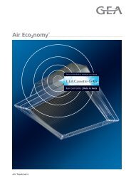
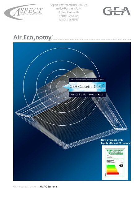
Precise air distribution, maximum use of spaceGEA Cassette-Geko ®Fan Coil Units | Data & FactsNow available withhighly efficient EC motors!GEA Heat Exchangers / HVAC Systems
Table of ContentsGEA Cassette-Geko Fan Coil UnitOverview of Capacity .....................................................................3Fan Coil Unit Components ............................................................4Unit Selection .................................................................................5Unit Description .............................................................................6EC Technology: Keyword Energy Efficiency ...............................8Description of Components ........................................................12Pressure Drops in Heat Exchanger forWarm and Chilled Water...............................................................32Example for Capacity Determination ..........................................33Acoustics ......................................................................................34Sound Pressure Level, Sound Power Level .............................. 36NR and NC Limit Curves .............................................................37Dimensions/Weight of Basic Units .............................................33Accessories / Primary Air Supply ..............................................38Air Distribution .............................................................................43Control Behaiviour of Valves ......................................................39Overview of Valves ......................................................................44Valves (loose) with modulating actuator(230 V~ and 24 V~)/3-point operation............................................................. 46Valves with modulating actuator (230 V~) a. 2 floating auxiliary switches/3-point operation ............................................................................................. 47Valves with thermoelectrical Actuators(230 V~ and 24 V~)/on/off operation............................................................... 48Valves with contunuous actuators (24 V~, 0..10 V) ........................................ 49Shut off valves................................................................................................. 50Regulation via Thermostat / Speed Switches/Regulation by Others....................................................................52Controls System GEA MATRIX ® ..................................................54System Description ......................................................................................... 54Description of Features ................................................................................... 56Installing Control Panels ................................................................................. 57Sensor / Accessories ...................................................................................... 58Global Modules ............................................................................................... 59Timer MATRIX.Clock ...................................................................................... 60Control Panel for All Groups ........................................................................... 61Service Tools................................................................................................... 62Unit Type Code..............................................................................632 PR-2010-0107-GB • Subject to modifications • Status 06/2011
GEA Cassette-Geko Fan Coil UnitOverview of CapacityUnits without Electrical HeatingModesizeMotortypeCS 1)Length xWidthAir flow rate Sound pressure level 2 Capacity EnEff class 4)•Heating duty Q 3)H•Cooling duty Q 3)KHeatingCooling[mm] [m3/h] [dB(A)] [kW]0250-460 25-352.2-4.71.5-2.5A B C D E F GA B C D E F GSingleAC12575 x 575330-660 26-43480-850 35-492.8-7.61.9-4.23.7-9.22.6-5.0A B C D E F GA B C D E F GA B C D E F GA B C D E F GEC 1250-850 25-492.2-9.21.5-5.0A B C D E F GA B C D E F GDoubleAC121175 x 575530-1000 30-47840-1400 40-544.7-12.43.2-6.86.7-16.04.6-8.8A B C D E F GA B C D E F GA B C D E F GA B C D E F GEC 1530-1400 30-544.7-16.03.2-8.8A B C D E F GA B C D E F GBigSingleAC12822 x 822620-1200 24-42770-1700 29-515.3-14.63.5-8.26.3-18.64.3-10.5A B C D E F GA B C D E F GA B C D E F GA B C D E F GEC 1620-1530 24-495.3-17.53.5-9.8A B C D E F GA B C D E F G1) CS = capacity stage2) Ambient conditions refer to page 34 "Acoustics".3)Capacity data only apply to units without electrical heating. Input parameters: PWW 70/50°C, tL1 = +20°C; PCW 6/12°C, tL1 = 27°C/46%r.h.4) EnEff class = Energy Efficiency Class according to EUROVENT refer to page 10.Correction factors 5)The correction factors listed belowcan be used to calculate thecapacity data in accordance withEUROVENT classificationconditions:Cooling (2+4-pipe system):1.01Heating (2-pipe system): 0.68Heating (4-pipe system): 1.23Sound power level 6) +3 dBCorrection factors f K forCorrection factors f H for• •cooling capacity Q Kheating capacity Q HChilledwatertemp.Air intake: t L1 [°C], ϕ 1 [% r.h.]Warmwatertemp.2-pipe systemair intake: t L1 [°C]4-pipe systemair intake: t L1 [°C][°C] 32/40 30/40 27/46 26/50 24/50 [°C] +10 +15 +20 +10 +15 +206/12 1.41 1.19 1.00 0.96 0.74 80/60 1.53 1.40 1.27 1.60 1.45 1.317/13 1.31 1.09 0.90 0.87 0.65 70/55 1.33 1.21 1.08 1.40 1.26 1.128/12 1.37 1.15 0.97 0.94 0.73 70/50 1.26 1.13 1.00 1.29 1.14 1.008/14 1.22 1.00 0.81 0.76 0.56 60/50 1.14 1.01 0.89 1.22 1.08 0.9310/15 1.09 0.89 0.70 0.66 0.49 60/40 0.98 0.85 0.71 0.98 0.82 0.6712/16 0.97 0.77 0.60 0.56 0.43 50/40 0.88 0.75 0.62 0.91 0.78 0.6312/18 0.82 0.65 0.49 0.43 0.33 40/30 0.61 0.47 0.33 0.62 0.47 0.3114/18 0.77 0.64 0.48 0.43 0.335) All indicated correction factors are arithmetically calculated for different unit configurations and are meant for approximate calculations ofcapacity data using other parameters. Exact data and other parameters can be obtained from our staff.6) Maximum indication due to EUROVENT zero tolerance.PR-2010-0107-GB • Subject to modifications • Status 06/2011 3
Components of Fan Coil UnitsUnit ComponentsGEA Cassette-Geko Fan Coil Unit71110126985413321Fig. 1:Pos. 1:Pos. 2:Pos. 3:Pos. 4:Pos. 5:Pos. 6:Pos. 7:Unit <strong>com</strong>ponents (depending on unit model)Intake grilleFilter fleeceDesign panel with air deflection vanesMain condensate trayFan with casingHeat exchanger (inc. optional electric heater)Basic casingPos. 8: Metal sheet electrical control boxwith control electronicsPos. 9: Lateral condensate trayPos. 10: Suspension bracketsPos. 11: Primary air connectionPos. 12: Opening for external air outletPos. 13: Condensate pumpGEA is a participant in the EUROVENT certification programme.The certified products are listed in the corresponding EUROVENT lists.4 PR-2010-0107-GB • Subject to modifications • Status 06/2011
Druckverluste im Wärmetauscher4 Rohrreihen Kühlen, 2-Leiter-System251322015109,08,07,06,05,04,54,0303,53,02,52,01,51,00,90,80,70,60,5506070801 9001502 02503 03504 04505 06 Wasservolumenstrom V W [l/h]7 08 09 01 0Abb. 25.3GEA Top-Geko • ˜nderungen vorbehalten • Stand 08/00 (D) 2515 02 0GEA Cassette-Geko Fan Coil UnitUnit SelectionUnit Description 6EC TechnologyKeyword Energy Efficiency [Energy Label] 8Recirculatingair4-Pipe Chilled and Warm Water 12Cooling andheating2-Pipe Chilled Water and Electrical Heating 16Cooling orheating2-Pipe Chilled or Warm Water 20Heating 2-Pipe Warm Water * 24Cooling 2-Pipe Chilled Water 28* Cassette-Geko for only-heating operation can not be subsequently converted for cooling operationDruckverlustDp [kPa]6 5 4 7Technical Data, Dimensionsand Description of Accessories 32Valves 45GEA MATRIX Control System/Thermostat Switches 52PR-2010-0107-GB • Subject to modifications • Status 06/2011 5
Unit DescriptionGEA Cassette-Geko Fan Coil UnitSingle basic unit 2-pipe systemBasic unit with valve equipment andlateral drain pan (installation by others)Single/Double/Big SingleCassette unitHeating/cooling/filtering2/4-pipe system,ceiling installation.Unit made of galvanized metalsheet, flocked on the outside,with polyethylene soundinsulation and thermal insulationon the inside (electrical and valveequipment depends on functionsand requirements)Fig. 2ValvesValve equipment2 and 3-way valves withactuators for2-point 230/24 V~ 50/60 Hz,3-point 230/24 V~ 50/60 Hzcontinuous 24 V~,control signal 0-10 VFig. 3Electric equipmentElectric equipmentTerminal boxSteel sheet electrical control box(depending on unit model,function and requirements)Fig. 4Speed and thermostat switches MATRIX control system Controls andregulation systemsaccording tounit model, valves,internal and externalelectronic <strong>com</strong>ponentsFig. 56 PR-2010-0107-GB • Subject to modifications • Status 06/2011
GEA Cassette-Geko Fan Coil UnitUnit DescriptionHeat exchanger Singlefor warm and chilled waterFig. 6Heat exchanger Big Singlefor warm and chilled waterHeat exchanger:Copper pipes with attachedaluminium fins, connection ½"or ¾" internal thread(¾" connection on double andBig Single 2-pipe units and incooling circuit on Double andBig Single 4-pipe units), air vent/drain valves.Inlet temperatureHeating: max. 80 °CCooling: min. 6 °CMax. operating pressure: 16 barLateral drain pan Centrifugal fan Lateral drain panfor collecting condensate fromvalve pipework and transportingit to the main drain pan.Centrifugal fanwith selectable AC or highefficiency EC motors withbackward curved blades, singleinlet, with low-noise andmaintenance-free ball bearings,Fig. 7IP44 protection type,building material class BMain drain pan Single Main drain pan Big Single Main drain panmade of foamed polystyrene withintegrated air intake nozzle forfan, fire protection type B1Fig. 8Filter Design panel Double Synthetic washable filtermedium, easy to change, filterclassification G1 (EN 779)Fig. 9Design panel SingleDesign panel Big SingleDesign panelPanel with attractive andelegant design, consisting of:– Plastic frame andair intake grille– Air vanes, individuallyadjustable, optionally flocked– Wide range of coloursFig. 10PR-2010-0107-GB • Subject to modifications • Status 06/2011 7
EC-Technology: Keyword Energy EfficiencyGEA Cassette-Geko Fan Coil UnitWhat are EC motors?EC-motors (= electronically <strong>com</strong>mutated motors) are DCmotors, where the rotor is not performed as a coil, like inusual AC motors, but consists of a permanent magnet.Electronic control of the motor enables continuous operation,where the integrated electronics ensures alternatingmagnetic field which adjusts itself to the relevant speed(refer to Fig. 11). As <strong>com</strong>pared to mechanical <strong>com</strong>mutating(brushes), there are no moving regulation <strong>com</strong>ponentsthat generate additional losses.In such a way the motor operates at optimal conditions, resultingin maximum torque and minimum losses. The efficiencyrate of the EC motors used by GEA is twice as highas the <strong>com</strong>parable AC motors. The application of this technologyin GEA fan coil units makes it possible to achievehigh efficiency rates for fan motors - especially in part-loadmode.North poleRegulation RegulationCoilCoilSouth poleSouthNorth poleCurrent flow Current flowFig. 11: Functional description of an EC motor(electronical <strong>com</strong>mutation)This results in the reduction of electrical power consumption of an EC fan by up to 75%.100Comparison AC/EC fan - Single Cassette90Electrical power consumption [W]807060504030-75%47%-46%AC fan CS1AC fan CS2AC fan CS3EC fan-67%2010-74%-72%0200 300 400 500 600 700 800 900Air volume flow [m³/h]Fig. 12: Comparison - electrical power consumption EC/AC fan8 PR-2010-0107-GB • Subject to modifications • Status 06/2011
GEA Cassette-Geko Fan Coil UnitEC-Technology: Keyword Energy EfficiencyFurther aspects: – Continuous operation– Low generation of heat– Established and usual high motor quality– Same design for 50 and 60 HzContinuous GEA MATRIX controlsEC fans featuring continuous operation mode offer a few of benefits:– Room temperature control is performed with a higher accuracy, because occurringtemperature differences can be addressed with the accordingly adjusted fan speed.This effect is assisted by using 3-point regulation valves (hydraulic method).– Variable fan speed control can <strong>com</strong>pensate for fluctuating conditions of heating andcooling medium. Example: season-related different inlet temperature of heat generatoror fluctuating volume flow rates (hydraulics)– With standard AC fans the fan speed, which is optimal for room temperature control,must be adapted to the available fan speed stages which often leads to rapidincrease of motor RPM and thus electrical power consumption.– With continuous speed regulation - "hard" fan speed changes are eliminated, whichprovides additional acoustical <strong>com</strong>fort.The GEA MATRIX controls uses these features by making the following functionsavailable, the customer can select between automatic and manual operation:Automatic mode:Room temperature control with continuous regulation (1.5-10 V) of a stepless EC fan.The fan continuously operates within the minimum and maximum air volumes.Using the display control panel OP50/51 a speed limitation can be activated (mutefunction) in order to prevent an acoustic overshoot in automatic mode. This upper RPMlimit can be separately set for each control panel.As an additional measure to avoid possible on site acoustical resonance occurrences,up to three speed ranges can be hidden using MATRIX.PC software.Manual mode:OP 50/51 (control panel with display): continuous fan setting using rotary switchbetween minimum and maximum air volume flow rate.OP30/31 and OP44: (speed-stage control panel): 5-speed fan setting with speed1 = minimum air volume flow rate and speed 5 = maximum air volume flow rate.Percentage values (regarding maximum air volume flow rate) for speeds 2-4 arepre-configured by the factory (default values) and can be changed on site by othersusing MATRIX.PC.PR-2010-0107-GB • Subject to modifications • Status 06/2011 9
EC-Technology: Keyword Energy EfficiencyGEA Cassette-Geko Fan Coil UnitEUROVENT Energy LabelWithin the framework of EU regulations (Eco-Design Directive) clear limits will be setin the future with respect to the energy efficiency of available technological standards.EUROVENT, as the European Association of Manufacturers of HVAC equipment,anticipates this development by having published Energy Label for fan coil units toinclude 7 energy efficiency classes (A to G) in January 2011.In this case the energy efficiency is <strong>com</strong>posed of time-weighted relationship betweencooling or heating output and consumed electrical power of the fan.Fan coil units that are equipped with an energy-efficient temperature regulation system(GEA MATRIX) and, depending on situation-related heating or cooling demand, reactwith adjusted fan speed must consider the time share of the corresponding speedstages for the evaluation of energy efficiency. For the description of time-connectedrelationships EUROVENT uses coefficient A (maximum), B (medium) and C (minimumspeed). These indicators vary, depending on heating or cooling operation mode.Fan stage Coefficient Time percentageCooling HeatingHigh (maximum) A 5 % 5 %Medium B 30 % 25 %Low (minimum) C 65 % 70 %The energy efficiency relationship is <strong>com</strong>posed of time-weighted shares and ispresented in the examples using the following formulas:Cooling (FCEER):••••A × QFCEERKHighSpeed+ B×Q KMediumSpeed+ C×Q= -----------------------------------------------------------------------------------------------------------------------------------------------KLowSpeedA×Pe HighSpeed+ B×Pe MediumSpeed+ C×QPe LowSpeedFan Coil Energy Efficiency Ratio - total cooling capacity(= Energy efficiency relationship)Heating (FCCOP):FCCOP=• • •A×Q HHighSpeed+ B×Q HMediumSpeed+ C×Q-----------------------------------------------------------------------------------------------------------------------------------------------HLowSpeedA×Pe HighSpeed+ B × Pe MediumSpeed+ C×Pe LowSpeedFan Coil Coefficient Of Performance(= Performance coefficient of fan coil unit)•with Q K = Total cooling capacity•mit Q H = Heating capacitymit Pe = Electrical power consumption of fanHigher numerical value of these indicators stands for especially outstanding energyefficiency.10 PR-2010-0107-GB • Subject to modifications • Status 06/2011
GEA Cassette-Geko Fan Coil UnitEC-Technology: Keyword Energy EfficiencyFor the corresponding energy label the EUROVENT performs the followingclassification:FCEER (Total)Class ValueA = 185B = 120C = 80D = 55E = 40F = 30G = 0FCCOPClass ValueA = 265B = 160C = 100D = 70E = 50F = 40G = 0Example:GEA-Single Cassette-Geko GSC1.UWW.SE5[unit type code for a 4-pipe unit with an EC fan]Cooling (FCEER)*:FCEER5% × 3, 21 + 30% × 2, 61 + 65% × 1,99=5% ----------------------------------------------------------------------------------------------------------- =× 0, 026 + 30% × 0, 014 + 65% × 0,008209 ≥ 185 CLASS ALabelHeating (FCCOP)*:FCEERLabel=5% × 5, 63 + 25% × 4, 54 + 70% × 3,445% ----------------------------------------------------------------------------------------------------------- =× 0, 026 + 25% × 0, 014 + 70% × 0,008367 ≥ 265 CLASS A*) Cooling, heating and electrical output in [kW] under EUROVENT conditions:Cooling: air intake 27°C / 47% r.h., chilled water 7 / 12°CHeating: air intake 20°C, warm water 70 / 60°CData for unit types as defined by the EUROVENT classification can be calculated usingour AiD@ layout software or provided by our sales representatives.PR-2010-0107-GB • Subject to modifications • Status 06/2011 11
Recirculating Air Unit Cooling and Heating4-Pipe Chilled and Warm WaterSizes Single, Double and Big SingleChilled water6/12 °Ct L1 = +27 °Cϕ 1 = 46 % r.h.Warm water70/50 °Ct L1 = +20 °CGEA Cassette-Geko Fan Coil UnitCapacity stage 0 Capacity stage 1 Capacity stage 2Model sizeSDBMotor typeACECACECACECSpeedsAir ?ow rateCooling capacityPressure dropHeating capacityPressure dropCooling capacityPressure drop•Q K Δp K•Q H Δp H•Q K Δp K•Q H Δp H•Q K Δp K•Q H Δp H[m 3 /h] kW kPa kW kPa kW kPa kW kPa kW kPa kW kPa dB(A) dB(A)1 250 1.5 1.9 2.2 0.8 - - - - - - - - 34 252 310 1.8 2.7 2.7 1.2 - - - - - - - - 35 263 460 2.5 4.6 3.6 2.0 - - - - - - - - 44 351 330 - - - - 1.9 2.9 2.8 1.3 - - - - 35 262 480 - - - - 2.6 4.9 3.7 2.1 - - - - 43 343 660 - - - - 3.2 7.3 4.5 3.1 - - - - 52 431 480 - - - - - - - - 2.6 4.9 3.7 2.1 44 352 710 - - - - - - - - 3.3 8.0 4.8 3.4 54 453 850 - - - - - - - - 3.7 9.6 5.4 4.3 58 49min 250 - - - - 1.5 1.9 2.2 0.8 - - - - 28 192 330 - - - - 1.9 2.9 2.8 1.3 - - - - 35 263 480 - - - - 2.6 4.9 3.7 2.1 - - - - 44 354 660 - - - - 3.2 7.3 4.5 3.1 - - - - 52 43max 850 - - - - 3.7 9.6 5.4 4.3 - - - - 58 491 530 - - - - 3.2 2.1 4.7 0.9 - - - - 38 302 740 - - - - 4.2 3.5 6.1 1.5 - - - - 47 393 1000 - - - - 5.3 5.2 7.6 2.2 - - - - 56 471 840 - - - - - - - - 4.6 4.1 6.7 1.8 48 402 1220 - - - - - - - - 6.0 6.6 8.7 2.9 59 503 1400 - - - - - - - - 6.6 7.9 9.4 3.4 62 54min 530 - - - - 3.2 2.1 4.7 0.9 - - - - 38 292 740 - - - - 4.2 3.5 6.1 1.5 - - - - 46 373 1000 - - - - 5.3 5.2 7.6 2.2 - - - - 53 454 1220 - - - - 6.0 6.6 8.7 2.9 - - - - 58 50max 1400 - - - - 6.6 7.9 9.4 3.4 - - - - 62 531 620 - - - - 3.5 1.8 5.3 1.1 - - - - 32 232 920 - - - - 4.9 3.3 7.2 2.0 - - - - 43 353 1200 - - - - 5.9 4.7 8.7 2.8 - - - - 50 421 770 - - - - - - - - 4.3 2.6 6.3 1.6 38 292 1150 - - - - - - - - 5.8 4.5 8.4 2.7 49 413 1700 - - - - - - - - 7.4 7.0 10.8 4.2 59 51min 620 - - - - 3.5 1.8 5.3 1.1 - - - - 32 232 770 - - - - 4.3 2.6 6.3 1.6 - - - - 38 293 920 - - - - 4.9 3.3 7.2 2.0 - - - - 43 344 1150 - - - - 5.8 4.5 8.4 2.7 - - - - 49 40max 1530 - - - - 6.9 6.2 10.1 3.7 - - - - 56 480 1 2Capacity stageTerminal box(select metal sheet electricalswitch box for GEA MATRIX®)(only for Single and Double)Speed <strong>com</strong>bination1 – 2 – 3 AHeating capacityPressure dropMetal sheet electric control boxwith terminal strip orfor integrated controlMotor thermal contact3-speed motorEC motorSpeed <strong>com</strong>bination1 – 2 – 3 Kmin...maxIntegrated TC 0External TC 1ESCooling capacityPressure dropHeating capacityColour123459Pressure dropSound powerSound pressure*Design panel similar to RAL9003 (signal white),Air vanes similar to RAL6034 (pastel turquoise)Design panel similar to RAL9003 (signal white),Air vanes flocked, similar toRAL 6034 (pastel turquoise)Design panel similar to RAL9003 (signal white),Air vanes similar to RAL7035 (light grey)Design panel similar to RAL9003 (signal white),Air vanes flocked, similar toRAL 7035 (light grey)Design panel similar to RAL9003 (signal white),Air vanes similar to RAL9003 (signal white)Colour shade of choice(design panel and unflockedair vanes only)G C . U W W . Order code* For ambient conditions refer to page 34 "Acoustics"12 PR-2010-0107-GB • Subject to modifications • Status 06/2011
GEA Cassette-Geko Fan Coil UnitAccessories/ValvesRecirculating Air Unit Cooling and Heating4-Pipe Chilled and Warm Water, Sizes Single, Double and Big SingleAccessoriesSpare filter(Single and Big Single = 4 pieces, Double = 8 pieces)1 1 1Mounting bracket set 1 1 2Model sizes S, D, B, 0 *Order codeZ G C 1 1 1* 0 - if regardless of model sizeValvesHeating circuitMATRIX 500MATRIX 2000MATRIX 3000Terminal boxCooling circuitk vs -valuesActuator Operating voltage/circuit Cooling/Heating• • • • 2-point open/230 V AC T1.60 ≡ 1 6• • • close24 V AC * Q 2.50 ≡ 2 5• •230 V AC R3-point open/• • 24 V AC * Nstop/close0.25 ≡ 0 30.40 ≡ 0 40.63 ≡ 0 61.00 ≡ 1 02 3 8 9 1.60 ≡ 1 6• • 230 V AC with auxiliary switch C2.50 ≡ 2 5• continuous 0/2...10 V = 24 V AC * S 4.00 ≡ 4 0• •• •mixed230 V AC Heating circuit 3-P230 V AC Cooling circuit 2-P24 V AC Heating circuit 3-P *24 V AC Cooling circuit 2-P *with shut off valve 1without shut off valve 013kvs-values indicated abovefor open/close actuators(T,Q) only kvs 1.6 and 2.5CoolingHeatingSizesSingleDoubleBig SingleSDB* 24 V transformer to be provided by othersOrder codeV .PR-2010-0107-GB • Subject to modifications • Status 06/2011 13
onfuncsend%Control ComponentsRecirculating Air Unit Cooling and Heating4-Pipe Chilled and Warm Water, Sizes Single, Double and Big SingleGEA Cassette-Geko Fan Coil UnitGEA MATRIX 500/2000 (not for EC motor)System features:– Temperature assignment.: 10..30 °C– Manual assignment of speed stage– Limitable setting range– Change-over between normal/economy mode on control panel– Indoor temperature measurement using control panel– External indoor temperature sensor can be connected– Valve control (2-point)– Temperature control via fan on/off and valve(s)– Status messages using LED– Group control– Group switch-off switch-off in case of fault– Temperature monitoring of motor(TC required)Additional features MATRIX 2000:– Extended temperature assignment.: 7...40 °C (default 10..30 °C)– Temperature control via fan speed change and valve(s)– Network capabilityMATRIX OP5CControl panel for MATRIX 500– Pure white casing, protection type IP20– Setpoint temperature setting– Speed stage selection switch 0-A (continuous)-1-2-3– Economy mode button– LEDs for operation/fault/ext.control– Integrated indoor temperature sensorMATRIX OP21CControl panel for MATRIX 2000, like control panelOP5C, but with additional:– Speed stage selection switch 0-A (Auto)-1-2-3TAGEA MATRIX 3000System features MATRIX 3000– Temperature assignment: 7 ... 40 °C (default 10 ... 30 °C)– Speed (stage) assignment– Limitable setting range– Change-over between normal/economy mode on control panel– Input for change-over between normal/economy mode or unit OFFwith frost protection– Indoor temperature measurement using control panel– External indoor temperature sensor can be connected– Valve control (2x2 or 2x3 point)– Temperature control via fan and/or valve(s)– Room frost protection– Status messages using LED– Status and fault signals using floating change-over contacts– Unit individual and group control– Isolation of individual units in case of fault– Temperature monitoring of motor(with speed stage motors TC required)– Network capabilityMATRIX OP30CControl panel for MATRIX 3000– Pure white casing, protection type IP20– Setpoint temperature setting– Speed-stage selection switch 0-A(Auto)-1-2-3-4-5(Stages 4 and 5 only in connection with EC motor)– LEDs for operation/fault/ext.control– Integrated indoor temperature sensorMATRIX OP31CLike control panel OP30C, but with additional:– Normal/economy mode buttonsMATRIX OP44CLike control panel OP31C, but with additional button for:– Change-over recirculating / mixed air mode– Change-over heating/cooling/automatic modeBCDMATRIX OP50CControl panel for MATRIX 3000– Pure white casing, protection type IP20– Menu-guided controls using rotation navigator– LCD clear text display– Status messages using pictograms– Integrated indoor temperature sensor– Continuous speed assignment (only in connectionwith EC motor)MATRIX OP51CEFLike control panel OP50C, but with additional:– Integrated weekly clock timer with a holiday and specialdays programmeMATRIX.IRInfrared remote control for control system MATRIX3000/4000– Black casing, RAL 9004– LCD display approx. 45x30 mm– Functions as in OP44C (without status, fault andexternal control signals, no integrated indoortemperature sensor, only 0-A-1-2-3 speed selection)– Maximum range 20 moff- +N14 PR-2010-0107-GB • Subject to modifications • Status 06/2011
GEA Cassette-Geko Fan Coil UnitControl ComponentsRecirculating Air Unit Cooling and Heating4-Pipe Chilled and Warm Water, Sizes Single, Double and Big SingleMasterunitSlave units1-15With controller type:D0 = 7x2x0.8D2 = 4x2x0.8 J-Y(ST)YWith controller type:D0 = 7x2x0.8D2 = 4x2x0.8 J-Y(ST)Y3x1.5 mm 2 NYM3x1.5 mm 2 NYMCooling/heat.medium230 V~50 Hzwithout return air sensor * 0with return air sensor * 5Order code MATRIX 500Order code MATRIX 2000D 0 . 5 1 . T AD 2 . 2 1 . A AD 0 . 5 0 1 . Z DD 2 . 2 0 1 . Z De.g. 2x2x0.5 HelukabelMasterunitWith controller type:D2 = 4x2x0.8 J-Y(ST)YD3/4 = e.g. 1x2x0.5 HelukabelSlave units1-153x1.5 mm 2 NYM 3x1.5 mm 2 NYMCooling/heat.medium230 V~50 HzSpeed (stages)Stand alone unitcontrol with operatingand error messagingUnit group control withoperation and errormessagingInput unit OFF withindoor frost protectionEconomy modecontact inputSupply air temperaturelimitationup to3 speedup to 3speedscontinuous• • 1 2 0 1• • 2 2 0 1• • 1 3 1• • 2 3 2• • • 3 3 3• • • 4 3 4without return air sensor * 0with return air sensor * 5control panelOrder codeD 3 . 2 . A D . 2 . Z D* Alternative room temperature sensor (see page 53)Master unitSlave unit(s)PR-2010-0107-GB • Subject to modifications • Status 06/2011 15
Recirculating Air Unit Cooling and Heating2-Pipe Chilled and Warm WaterSizes Single, Double and Big SingleChilled water6/12 °Ct L1 = +27 °Cϕ 1 = 46 % r.h.Electric heating230V~N/P/E50HzGEA Cassette-Geko Fan Coil UnitModel sizeSDBMotor typeACECACECACECSpeedAir volumeflowCoolingcapacityCapacity stage 0 Capacity stage 1 Capacity stage 2PressuredropHeatingcapacityPressuredropCoolingcapacityPressuredrop•Q K Δp K•Q H Δp H•Q K Δp K•Q H Δp H•Q K Δp K•Q H Δp H[m 3 /h] kW kPa kW kPa kW kPa kW kPa kW kPa kW kPa dB(A) dB(A)1 250 1.5 1.9 1.0 - - - - - - - - - 34 252 310 1.8 2.7 1.0 - - - - - - - - - 35 263 460 2.5 4.6 1.0 - - - - - - - - - 44 351 330 - - - - 2.4 3.4 1.0 - - - - - 35 262 480 - - - - 3.3 5.9 1.0 - - - - - 43 343 660 - - - - 4.2 9.4 1.0 - - - - - 52 431 480 - - - - - - - - 3.3 5.9 2.0 - 44 352 710 - - - - - - - - 4.4 10.3 2.0 - 54 453 850 - - - - - - - - 5.0 12.8 2.0 - 58 49min 250 - - - - 1.9 2.1 1.0 - - - - - 28 192 330 - - - - 2.4 3.4 1.0 - - - - - 35 263 480 - - - - 3.3 5.9 1.0 - - - - - 44 354 660 - - - - 4.2 9.4 1.0 - - - - - 52 43max 850 - - - - 5.0 12.8 1.0 - - - - - 58 49min 480 - - - - - - - - 3.3 5.9 2.0 - 44 352 570 - - - - - - - - 3.8 7.8 2.0 - 48 393 660 - - - - - - - - 4.2 9.4 2.0 - 52 434 710 - - - - - - - - 4.4 10.3 2.0 - 54 45max 850 - - - - - - - - 5.0 12.8 2.0 - 58 491 530 - - - - 4.0 2.4 2.0 - - - - - 38 302 740 - - - - 5.3 4.1 2.0 - - - - - 47 393 1000 - - - - 6.8 6.3 2.0 - - - - - 56 471 840 - - - - - - - - 5.9 4.9 4.0 - 48 402 1220 - - - - - - - - 8.0 8.5 4.0 - 59 503 1400 - - - - - - - - 8.8 10.1 4.0 - 62 54min 530 - - - - 4.0 2.4 2.0 - - - - - 38 292 740 - - - - 5.3 4.1 2.0 - - - - - 46 373 1000 - - - - 6.8 6.3 2.0 - - - - - 53 454 1220 - - - - 8.0 8.5 2.0 - - - - - 58 50max 1400 - - - - 8.8 10.1 2.0 - - - - - 62 53min 840 - - - - - - - - 5.9 4.9 4.0 - 49 402 1000 - - - - - - - - 6.8 6.3 4.0 - 53 453 1110 - - - - - - - - 7.4 7.4 4.0 - 56 474 1220 - - - - - - - - 8.0 8.5 4.0 - 58 50max 1400 - - - - - - - - 8.8 10.1 4.0 - 62 531 620 - - - - 4.8 4.8 2.0 - - - - - 32 232 920 - - - - 6.7 8.6 2.0 - - - - - 43 353 1200 - - - - 8.2 12.3 2.0 - - - - - 50 421 770 - - - - - - - - 5.8 6.6 3.0 - 38 292 1150 - - - - - - - - 7.9 11.6 3.0 - 49 413 1700 - - - - - - - - 10.4 19.4 3.0 - 59 51min 620 - - - - 4.8 4.8 2.0 - - - - - 32 232 770 - - - - 5.8 6.6 2.0 - - - - - 38 293 920 - - - - 6.7 8.6 2.0 - - - - - 43 344 1150 - - - - 7.9 11.6 2.0 - - - - - 49 40max 1530 - - - - 9.7 17.0 2.0 - - - - - 56 48min 770 - - - - - - - - 5.8 6.6 3.0 - 38 292 920 - - - - - - - - 6.7 8.6 3.0 - 43 343 1150 - - - - - - - - 7.9 11.6 3.0 - 49 404 1340 - - - - - - - - 8.9 14.4 3.0 - 53 44max 1530 - - - - - - - - 9.7 17.0 3.0 - 56 480 1 2Capacity stageHeatingcapacityPressuredropCoolingcapacityPressuredropHeatingcapacityPressuredropSoundpowerSoundpressure *Motor thermal contactIntegrated TC 03-speed motorExternal TC 1EC motorE123459ColourDesign panel similar to RAL9003 (signal white),Air vanes similar to RAL6034 (pastel turquoise)Design panel similar to RAL9003 (signal white),Air vanes flocked, similar toRAL 6034 (pastel turquoise)Design panel similar to RAL9003 (signal white),Air vanes similar to RAL7035 (light grey)Design panel similar to RAL9003 (signal white),Air vanes flocked, similar toRAL 7035 (light grey)Design panel similar to RAL9003 (signal white),Air vanes similar to RAL9003 (signal white)Colour shade of choice(design panel and unflockedair vanes only)G C . U W E . K Order code * For ambient conditions refer to page 34 "Acoustics"16 PR-2010-0107-GB • Subject to modifications • Status 06/2011
GEA Cassette-Geko Fan Coil UnitAccessories/ValvesRecirculating Air Unit Cooling and Heating2-Pipe Chilled Water and E-Heating, Sizes Single, Double and Big SingleAccessoriesSpare filter(Single and Big Single = 4 pieces, Double = 8 pieces)1 1 1Mounting bracket set 1 1 2Model sizes S, D, B, 0 *Order codeZ G C 1 1 1* 0 - if regardless of model sizeValvesMATRIX 500MATRIX 2000MATRIX 3000Terminal boxCooling circuitk vs -valuesActuator Operating voltage/circuit Cooling• • • • 2-point open/230 V AC T1.60 ≡ 1 6• • • close24 V AC * Q 2.50 ≡ 2 5• •230 V AC R3-point open/• • 24 V AC * Nstop/close0.25 ≡ 0 30.40 ≡ 0 40.63 ≡ 0 61.00 ≡ 1 02 31.60 ≡ 1 6• • 230 V AC with auxiliary switch C2.50 ≡ 2 5• continuous 0/2...10 V = 24 V AC * S 4.00 ≡ 4 0kvs-values as indicatedabove for open/closeactuators (T,Q)only kvs 1.6 and 2.5 possiblewith shut off valve 1without shut off valve 0SizesSingleDoubleBig SingleSDB* 24 V transformer to be provided by othersOrder codeV .PR-2010-0107-GB • Subject to modifications • Status 06/2011 17
GEA Cassette-Geko Fan Coil UnitControl ComponentsRecirculating Air Unit Cooling and Heating2-Pipe Chilled Water and E-Heating, Sizes Single, Double and Big SingleMasterunit230 V~50 HzSlave units1-15230 V~50 HzWith controller type:D0 = 7x2x0.8D2 = 4x2x0.8 J-Y(ST)YWith controller type:D0 = 7x2x0.8D2 = 4x2x0.8 J-Y(ST)Y3x1.5 mm 2 NYM3x2.5 mm 2 NYM3x1.5 mm 2 NYM3x2.5 mm 2 NYM230 V~50 Hz230 V~50 Hz230 V~50 HzCooling mediumwithout return air sensor * 2 0with return air sensor * 7 5Order code MATRIX 500Order code MATRIX 2000D 0 . 5 2 . T AD 2 . 2 1 . A AD 0 . 5 0 2 . Z DD 2 . 2 2 1 . Z DMasterunit230 V~50 HzSlave units1-15230 V~50 Hze.g. 2x2x0.5 HelukabelWith controller type:D2 = 4x2x0.8 J-Y(ST)YD3/4 = e.g. 1x2x0.5 Helukabel3x1.5 mm 2 NYM3x2.5 mm 2 NYM3x1.5 mm 2 NYM3x2.5 mm 2 NYM230 V~50 Hz230 V~50 Hz230 V~50 HzCooling mediumSpeed (stages)Stand alone unit controlwith operating anderror messagingUnit group control withoperation and errormessagingInput unit OFF withindoor frost protectionEconomy mode contactinputSupply air temperaturelimitationup to3 speedup to 3speedscontinuous• • 1 2 2 1• • 2 2 1• • 1 3 1• • 2 3 2• • • 3 3 3• • • 4 3 4without return air sensor * 2with return air sensor * 7control panelOrder codeD 3 . 2 . A D . 2 . Z D* Alternative room temperature sensor (see page 53)Master unitSlave unit(s)PR-2010-0107-GB • Subject to modifications • Status 06/2011 19
Recirculating Air Unit Cooling or Heating2-Pipe Chilled or Warm WaterSizes Single, Double and Big SingleChilled water6/12 °Ct L1 = +27 °Cϕ 1 = 46 % r.h.Warm water70/50 °Ct L1 = +20 °CGEA Cassette-Geko Fan Coil UnitCapacity stage 0 Capacity stage 1 Capacity stage 2Model sizeSDBMotor typeACECACECACECSpeedsAir fow rateCooling capacityPressure dropHeating capacityPressure dropCooling capacityPressure dropHeating capacity•Q K Δp K•Q H Δp H•Q K Δp K•Q H Δp H•Q K Δp K•Q H Δp H[m 3 /h] kW kPa kW kPa kW kPa kW kPa kW kPa kW kPa dB(A) dB(A)1 250 1.5 1.9 2.9 0.6 - - - - - - - - 34 252 310 1.8 2.7 3.5 0.8 - - - - - - - - 35 263 460 2.5 4.6 4.7 1.4 - - - - - - - - 44 351 330 - - - - 2.4 3.4 4.4 0.9 - - - - 35 262 480 - - - - 3.3 5.9 6.0 1.7 - - - - 43 343 660 - - - - 4.2 9.4 7.6 2.6 - - - - 52 431 480 - - - - - - - - 3.3 5.9 6.0 1.7 44 352 710 - - - - - - - - 4.4 10.3 8.1 2.9 54 453 850 - - - - - - - - 5.0 12.8 9.2 3.7 58 49min 250 - - - - 1.9 2.1 3.5 0.6 - - - - 28 192 330 - - - - 2.4 3.4 4.4 0.9 - - - - 35 263 480 - - - - 3.3 5.9 6.0 1.7 - - - - 44 354 660 - - - - 4.2 9.4 7.6 2.6 - - - - 52 43max 850 - - - - 5.0 12.8 9.2 3.7 - - - - 58 491 530 - - - - 4.0 2.4 7.3 0.7 - - - - 38 302 740 - - - - 5.3 4.1 9.7 1.1 - - - - 47 393 1000 - - - - 6.8 6.3 12.4 1.8 - - - - 56 471 840 - - - - - - - - 5.9 4.9 10.8 1.4 48 402 1220 - - - - - - - - 8.0 8.5 14.4 2.4 59 503 1400 - - - - - - - - 8.8 10.1 16.0 2.8 62 54min 530 - - - - 4.0 2.4 7.3 0.7 - - - - 38 292 740 - - - - 5.3 4.1 9.7 1.1 - - - - 46 373 1000 - - - - 6.8 6.3 12.4 1.8 - - - - 53 454 1220 - - - - 8.0 8.5 14.4 2.4 - - - - 58 50max 1400 - - - - 8.8 10.1 16.0 2.8 - - - - 62 531 620 - - - - 4.9 5.2 8.6 1.4 - - - - 32 232 920 - - - - 6.7 9.2 11.8 2.4 - - - - 43 353 1200 - - - - 8.2 13.2 14.6 3.6 - - - - 50 421 770 - - - - - - - - 5.9 7.2 10.2 1.8 38 292 1150 - - - - - - - - 7.9 12.4 14.2 3.4 49 413 1700 - - - - - - - - 10.5 20.8 18.9 5.7 59 51min 620 - - - - 4.9 5.2 8.6 1.4 - - - - 32 232 770 - - - - 5.9 7.2 10.2 1.8 - - - - 38 293 920 - - - - 6.7 9.2 11.8 2.4 - - - - 43 344 1150 - - - - 7.9 12.4 14.2 3.4 - - - - 49 40max 1530 - - - - 9.8 18.2 17.5 4.9 - - - - 56 480 1 2Capacity stagePressure dropCooling capacityPressure dropHeating capacityPressure dropSound powerSound pressure*Terminal box(select metal sheet electricalswitch box for GEA MATRIX®)(only for Single and Double)Speed <strong>com</strong>bination1 – 2 – 3 AMetal sheet electric control boxwith terminal strip orfor integrated controlMotor thermal contact3-speed motorEC motorSpeed <strong>com</strong>bination1 – 2 – 3 Kmin...max SIntegrated TC 0External TC 1E123459ColourDesign panel similar to RAL9003 (signal white),Air vanes similar to RAL6034 (pastel turquoise)Design panel similar to RAL9003 (signal white),Air vanes flocked, similar toRAL 6034 (pastel turquoise)Design panel similar to RAL9003 (signal white),Air vanes similar to RAL7035 (light grey)Design panel similar to RAL9003 (signal white),Air vanes flocked, similar toRAL 7035 (light grey)Design panel similar to RAL9003 (signal white),Air vanes similar to RAL9003 (signal white)Colour shade of choice(design panel and unflockedair vanes only)G C . U W C . Order code* For ambient conditions refer to page 34 "Acoustics"20 PR-2010-0107-GB • Subject to modifications • Status 06/2011
GEA Cassette-Geko Fan Coil UnitAccessories/ValvesRecirculating Air Unit Cooling or Heating2-Pipe Chilled or Warm Water, Sizes Single, Double and Big SingleAccessoriesSpare filter(Single and Big Single = 4 pieces, Double = 8 pieces)1 1 1Mounting bracket set 1 1 2Model sizes S, D, B, 0 *Order codeZ G C 1 1 1* 0 - if regardless of model sizeValvesMATRIX 500MATRIX 2000MATRIX 3000Terminal boxHeating circuit/cooling circuitk vs -valuesActuator Operating voltage/circuit Cooling/Heating• • • • 2-point open/230 V AC T 1.60 ≡ 1 6• • • close24 V AC * Q 2.50 ≡ 2 5• • •230 V AC R3-point open/• • • 24 V AC * Nstop/close0.25 ≡ 0 30.40 ≡ 0 40.63 ≡ 0 61.00 ≡ 1 01.60 ≡ 1 6• • • 230 V AC with auxiliary switch C2.50 ≡ 2 5• continuous 0/2...10 V = 24 V AC * S 4.00 ≡ 4 0kvs-values as indicatedabove for open/closeactuators (T,Q)only kvs 1.6 and 2.5 possiblewith shut off valve 1without shut off valve 0SizesSingleDoubleBig SingleSDB* 24 V transformer to be provided by othersOrder codeV 3 .PR-2010-0107-GB • Subject to modifications • Status 06/2011 21
onfuncsend%Control ComponentsRecirculating Air Unit Cooling or Heating2-Pipe Chilled or Warm Water, Sizes Single, Double and Big SingleGEA Cassette-Geko Fan Coil UnitGEA MATRIX 500/2000 (not for EC motor)System features:– Temperature assignment.: 10..30 °C– Manual assignment of speed stage– Limitable setting range– Change-over between normal/economy mode on control panel– Indoor temperature measurement using control panel– External indoor temperature sensor can be connected– Valve control (2-point)– Temperature control via fan on/off and valve(s)– Status messages using LED– Group control– Group switch-off switch-off in case of fault– Temperature monitoring of motor(TC required)Additional features MATRIX 2000:– Extended temperature assignment.: 7...40 °C (default 10..30 °C)– Temperature control via fan speed change and valve(s)– Network capabilityMATRIX OP5CControl panel for MATRIX 500– Pure white casing, protection type IP20– Setpoint temperature setting– Speed stage selection switch 0-A (continuous)-1-2-3– Economy mode button– LEDs for operation/fault/ext.control– Integrated indoor temperature sensorMATRIX OP21CControl panel for MATRIX 2000, like control panelOP5C, but with additional:– Speed stage selection switch 0-A (Auto)-1-2-3TAGEA MATRIX 3000System features MATRIX 3000– Temperature assignment: 7 ... 40 °C (default 10 ... 30 °C)– Speed (stage) assignment– Limitable setting range– Change-over between normal/economy mode on control panel– Input for change-over between normal/economy mode or unit OFFwith frost protection– Indoor temperature measurement using control panel– External indoor temperature sensor can be connected– Valve control (2x2 or 2x3 point)– Temperature control via fan and/or valve(s)– Room frost protection– Status messages using LED– Status and fault signals using floating change-over contacts– Unit individual and group control– Isolation of individual units in case of fault– Temperature monitoring of motor(with speed stage motors TC required)– Network capabilityMATRIX OP30CControl panel for MATRIX 3000– Pure white casing, protection type IP20– Setpoint temperature setting– Speed-stage selection switch 0-A(Auto)-1-2-3-4-5(Stages 4 and 5 only in connection with EC motor)– LEDs for operation/fault/ext.control– Integrated indoor temperature sensorMATRIX OP31CLike control panel OP30C, but with additional:– Normal/economy mode buttonsMATRIX OP44CLike control panel OP31C, but with additional button for:– Change-over recirculating / mixed air mode– Change-over heating/cooling/automatic modeBCDMATRIX OP50CControl panel for MATRIX 3000– Pure white casing, protection type IP20– Menu-guided controls using rotation navigator– LCD clear text display– Status messages using pictograms– Integrated indoor temperature sensor– Continuous speed assignment(only in connection with EC motor)MATRIX OP51CEFLike control panel OP50C, but with additional:– Integrated weekly clock timer with a holiday and specialdays programmeMATRIX.IRInfrared remote control for control system MATRIX3000/4000– Black casing, RAL 9004– LCD display approx. 45x30 mm– Functions as in OP44C (without status, fault andexternal control signals, no integrated indoor temperaturesensor, only 0-A-1-2-3 speed selection)– Maximum range 20 moff- +N22 PR-2010-0107-GB • Subject to modifications • Status 06/2011
GEA Cassette-Geko Fan Coil UnitControl ComponentsRecirculating Air Unit Cooling or Heating2-Pipe Chilled or Warm Water, Sizes Single, Double and Big SingleMasterunitSlave units1-15With controller type:D0 = 7x2x0.8D2 = 4x2x0.8 J-Y(ST)YWith controller type:D0 = 7x2x0.8D2 = 4x2x0.8 J-Y(ST)Y3x1.5 mm 2 NYM3x1.5 mm 2 NYMCooling/heat.medium230 V~50 Hz2x2x0.8 J-Y(ST)YOnly MATRIX 500without return air sensor * 1flow sensorwith return air sensor * 6Order code MATRIX 500Order code MATRIX 2000D 0 . 5 1 . T AD 2 . 1 0 1 . A AD 0 . 5 0 1 . Z DD 2 . 1 0 1 . Z De.g. 2x2x0.5 HelukabelMasterunitWith controller type:D2 = 4x2x0.8 J-Y(ST)YD3/4 = e.g. 1x2x0.5 HelukabelSlave units1-153x1.5 mm 2 NYM3x1.5 mm 2 NYMCooling/heat.medium230 V~50 Hz2x2x0.8 J-Y(ST)YFlow sensorSpeed (stages)Stand alone unit controlwith operating anderror messagingUnit group control withstatus and fault signalsInput unit OFF withindoor frost protectionEconomy modecontact inputSupply air temperaturelimitationup to3 speedup to 3speedscontinuous• • 1 2 0 1• • 2 2 0 1• • 1 3 1• • 2 3 2• • • 3 3 3• • • 4 3 4without return air sensor * 0with return air sensor * 5control panelOrder codeD 3 . 1 . A D . 1 . Z D* Alternative room temperature sensor (see page 53)Master unitSlave unit(s)PR-2010-0107-GB • Subject to modifications • Status 06/2011 23
Recirculating Air Unit Heating2-Pipe Warm WaterSizes Single, Double and Big SingleWarm water70/50 °Ct L1 = +20 °CGEA Cassette-Geko Fan Coil UnitCapacity stage 0 Capacity stage 1 Capacity stage 2Model sizeSDBMotor typeACECACECACECSpeedsAir ?ow rateCooling capacityPressure dropHeating capacityPressure dropCooling capacityPressure dropHeating capacity•QK Δp K•QH Δp H•QK Δp K•QH Δp H•QK Δp K•QH Δp H[m 3 /h] kW kPa kW kPa kW kPa kW kPa kW kPa kW kPa dB(A) dB(A)1 250 - - 2.9 0.6 - - - - - - - - 34 252 310 - - 3.5 0.8 - - - - - - - - 35 263 460 - - 4.7 1.4 - - - - - - - - 44 351 330 - - - - - - 4.4 0.9 - - - - 35 262 480 - - - - - - 6.0 1.7 - - - - 43 343 660 - - - - - - 7.6 2.6 - - - - 52 431 480 - - - - - - - - - - 6.0 1.7 44 352 710 - - - - - - - - - - 8.1 2.9 54 453 850 - - - - - - - - - - 9.2 3.7 58 49min 250 - - - - - - 3.5 0.6 - - - - 28 192 330 - - - - - - 4.4 0.9 - - - - 35 263 480 - - - - - - 6.0 1.7 - - - - 44 354 660 - - - - - - 7.6 2.6 - - - - 52 43max 850 - - - - - - 9.2 3.7 - - - - 58 491 530 - - - - - - 7.3 0.7 - - - - 38 302 740 - - - - - - 9.7 1.1 - - - - 47 393 1000 - - - - - - 12.4 1.8 - - - - 56 471 840 - - - - - - - - - - 10.8 1.4 48 402 1220 - - - - - - - - - - 14.4 2.4 59 503 1400 - - - - - - - - - - 16.0 2.8 62 54min 530 - - - - - - 7.3 0.7 - - - - 38 292 740 - - - - - - 9.7 1.1 - - - - 46 373 1000 - - - - - - 12.4 1.8 - - - - 53 454 1220 - - - - - - 14.4 2.4 - - - - 58 50max 1400 - - - - - - 16.0 2.8 - - - - 62 531 620 - - - - - - 8.6 1.4 - - - - 32 232 920 - - - - - - 11.8 2.4 - - - - 43 353 1200 - - - - - - 14.6 3.6 - - - - 50 421 770 - - - - - - - - - - 10.2 1.8 38 292 1150 - - - - - - - - - - 14.2 3.4 49 413 1700 - - - - - - - - - - 18.9 5.7 59 51min 620 - - - - - - 8.6 1.4 - - - - 32 232 770 - - - - - - 10.2 1.8 - - - - 38 293 920 - - - - - - 11.8 2.4 - - - - 43 344 1150 - - - - - - 14.2 3.4 - - - - 49 40max 1530 - - - - - - 17.5 4.9 - - - - 56 480 1 2Capacity stagePressure dropCooling capacityPressure dropHeating capacityPressure dropSound powerSound pressure*Terminal box(select metal sheet electricalswitch box for GEA MATRIX)(only for Single and Double)Speed <strong>com</strong>bination1 – 2 – 3 AMetal sheet electric control boxwith terminal strip orfor integrated controlMotor thermal contact3-speed motorSpeed <strong>com</strong>bination1 – 2 – 3 Kmin...maxIntegrated TC 0External TC 1S123459ColourDesign panel similar to RAL9003 (signal white),Air vanes similar to RAL6034 (pastel turquoise)Design panel similar to RAL9003 (signal white),Air vanes flocked, similar toRAL 6034 (pastel turquoise)Design panel similar to RAL9003 (signal white),Air vanes similar to RAL7035 (light grey)Design panel similar to RAL9003 (signal white),Air vanes flocked, similar toRAL 7035 (light grey)Design panel similar to RAL9003 (signal white),Air vanes similar to RAL9003 (signal white)Colour shade of choice(design panel and unflockedair vanes only)G C . U 0 W . Order code* For ambient conditions refer to page 34 "Acoustics"24 PR-2010-0107-GB • Subject to modifications • Status 06/2011
GEA Cassette-Geko Fan Coil UnitAccessories/ValvesRecirculating Air Unit Heating2-Pipe Warm Water, Sizes Single, Double and Big SingleAccessoriesSpare filter(Single and Big Single = 4 pieces, Double = 8 pieces)1 1 1Mounting bracket set 1 1 2Model sizes S, D, B, 0 *Order codeZ G C 1 1 1* 0 - if regardless of model sizeValvesMATRIX 500MATRIX 2000MATRIX 3000Terminal boxHeating circuitk vs -valuesActuator Operating voltage/circuit Heating• • • • 2-point open/230 V AC T1.60 ≡ 1 6• • • close24 V AC * Q 2.50 ≡ 2 5• • •230 V AC R3-point open/• • • 24 V AC * Nstop/close0.25 ≡ 0 30.40 ≡ 0 40.63 ≡ 0 61.00 ≡ 1 02 31.60 ≡ 1 6• • • 230 V AC with auxiliary switch C2.50 ≡ 2 5• continuous 0/2...10 V = 24 V AC * S 4.00 ≡ 4 0kvs-values as indicatedabove for open/closeactuators (T,Q)only kvs 1.6 and 2.5 possiblewith shut off valve 1without shut off valve 0SizesSingleDoubleBig SingleSDB* 24 V transformer to be provided by othersOrder codeV .PR-2010-0107-GB • Subject to modifications • Status 06/2011 25
GEA Cassette-Geko Fan Coil UnitControl ComponentsRecirculating Air Unit Heating2-Pipe Warm Water, Sizes Single, Double and Big SingleMasterunitSlave units1-15With controller type:D0 = 7x2x0.8D2 = 4x2x0.8 J-Y(ST)YWith controller type:D0 = 7x2x0.8D2 = 4x2x0.8 J-Y(ST)Y3x1.5 mm 2 NYM3x1.5 mm 2 NYMHeating medium230 V~50 Hzwithout return air sensor * 0with return air sensor * 5Order code MATRIX 500Order code MATRIX 2000D 0 . 5 1 . T AD 2 . 0 1 . A AD 0 . 5 0 1 . Z DD 2 . 0 0 1 . Z De.g. 2x2x0.5 HelukabelMasterunitWith controller type:D2 = 4x2x0.8 J-Y(ST)YD3/4 = e.g. 1x2x0.5 HelukabelSlave units1-153x1.5 mm 2 NYM3x1.5 mm 2 NYMHeating medium230 V~50 HzSpeed (stages)Stand alone unit controlwith operating anderror messagingUnit group control withstatus and fault signalsInput unit OFF withindoor frost protectionEconomy mode contactinputSupply air temperaturelimitationup to3 speedup to 3speedscontinuous• • 1 2 0 1• • 2 2 0 1• • 1 3 1• • 2 3 2• • • 3 3 3• • • 4 3 4without return air sensor * 0with return air sensor * 5control panelOrder codeD 3 . 0 . A D . 0 . Z DMaster unitSlave unit(s)PR-2010-0107-GB • Subject to modifications • Status 06/2011 27
Recirculating Air Unit Cooling2-Pipe Chilled WaterSizes Single, Double and Big SingleChilled water6/12 °Ct L1 = +27 °Cϕ 1 = 46 % r.h.GEA Cassette-Geko Fan Coil UnitCapacity stage 0 Capacity stage 1 Capacity stage 2Model sizeSDBMotor typeACECACECACECSpeedsAir ?ow rateCooling capacityPressure dropHeating capacityPressure dropCooling capacityPressure dropHeating capacity•Q K Δp K•Q H Δp H•QK Δp K•Q H Δp H•Q K Δp K•Q H Δp H[m 3 /h] kW kPa kW kPa kW kPa kW kPa kW kPa kW kPa dB(A) dB(A)1 250 1.5 1.9 - - - - - - - - - - 34 252 310 1.8 2.7 - - - - - - - - - - 35 263 460 2.5 4.6 - - - - - - - - - - 44 351 330 - - - - 2.4 3.4 - - - - - - 35 262 480 - - - - 3.3 5.9 - - - - - - 43 343 660 - - - - 4.2 9.4 - - - - - - 52 431 480 - - - - - - - - 3.3 5.9 - - 44 352 710 - - - - - - - - 4.4 10.3 - - 54 453 850 - - - - - - - - 5.0 12.8 - - 58 49min 250 - - - - 1.9 2.1 - - - - - - 28 192 330 - - - - 2.4 3.4 - - - - - - 35 263 480 - - - - 3.3 5.9 - - - - - - 44 354 660 - - - - 4.2 9.4 - - - - - - 52 43max 850 - - - - 5.0 12.8 - - - - - - 58 491 530 - - - - 4.0 2.4 - - - - - - 38 302 740 - - - - 5.3 4.1 - - - - - - 47 393 1000 - - - - 6.8 6.3 - - - - - - 56 471 840 - - - - - - - - 5.9 4.9 - - 48 402 1220 - - - - - - - - 8.0 8.5 - - 59 503 1400 - - - - - - - - 8.8 10.1 - - 62 54min 530 - - - - 4.0 2.4 - - - - - - 38 292 740 - - - - 5.3 4.1 - - - - - - 46 373 1000 - - - - 6.8 6.3 - - - - - - 53 454 1220 - - - - 8.0 8.5 - - - - - - 58 50max 1400 - - - - 8.8 10.1 - - - - - - 62 531 620 - - - - 4.9 5.2 - - - - - - 32 232 920 - - - - 6.7 9.2 - - - - - - 43 353 1200 - - - - 8.2 13.2 - - - - - - 50 421 770 - - - - - - - - 5.9 7.2 - - 38 292 1150 - - - - - - - - 7.9 12.4 - - 49 413 1700 - - - - - - - - 10.5 20.8 - - 59 51min 620 - - - - 4.9 5.2 - - - - - - 32 232 770 - - - - 5.9 7.2 - - - - - - 38 293 920 - - - - 6.7 9.2 - - - - - - 43 344 1150 - - - - 7.9 12.4 - - - - - - 49 40max 1530 - - - - 9.8 18.2 - - - - - - 56 480 1 2Capacity stagePressure dropCooling capacityPressure dropHeating capacityPressure dropSound powerSound pressure*Terminal box(select metal sheet electricalswitch box for GEA MATRIX)(only for Single and Double)Speed <strong>com</strong>bination1 – 2 – 3 AMetal sheet electric control boxwith terminal strip orfor integrated controlMotor thermal contact3-speed motorEC motorSpeed <strong>com</strong>bination1 – 2 – 3 Kmin...max SIntegrated TC 0External TC 1E123459ColourDesign panel similar to RAL9003 (signal white),Air vanes similar to RAL6034 (pastel turquoise)Design panel similar to RAL9003 (signal white),Air vanes flocked, similar toRAL 6034 (pastel turquoise)Design panel similar to RAL9003 (signal white),Air vanes similar to RAL7035 (light grey)Design panel similar to RAL9003 (signal white),Air vanes flocked, similar toRAL 7035 (light grey)Design panel similar to RAL9003 (signal white),Air vanes similar to RAL9003 (signal white)Colour shade of choice(design panel and unflockedair vanes only)G C . U W 0 . Order code* For ambient conditions refer to page 34 "Acoustics"28 PR-2010-0107-GB • Subject to modifications • Status 06/2011
GEA Cassette-Geko Fan Coil UnitAccessories/ValvesRecirculating Air Unit Cooling2-Pipe Chilled Water, Sizes Single, Double and Big SingleAccessoriesSpare filter(Single and Big Single = 4 pieces, Double = 8 pieces)1 1 1Mounting bracket set 1 1 2Model sizes S, D, B, 0 *Order codeZ G C 1 1 1* 0 - if regardless of model sizeValvesMATRIX 500MATRIX 2000MATRIX 3000Terminal boxCooling circuitk vs -valuesActuator Operating voltage/circuit Cooling• • • • 2-point open/230 V AC T1.60 ≡ 1 6• • • close24 V AC * Q 2.50 ≡ 2 5• • •230 V AC R3-point open/• • • 24 V AC * Nstop/close0.25 ≡ 0 30.40 ≡ 0 40.63 ≡ 0 61.00 ≡ 1 02 31.60 ≡ 1 6• • • 230 V AC with auxiliary switch C2.50 ≡ 2 5• continuous 0/2...10 V = 24 V AC * S 4.00 ≡ 4 0kvs-values as indicatedabove for open/closeactuators (T,Q)only kvs 1.6 and 2.5 possiblewith shut off valve 1without shut off valve 0SizesSingleDoubleBig SingleSDB* 24 V transformer to be provided by othersOrder codeV .PR-2010-0107-GB • Subject to modifications • Status 06/2011 29
onfuncsend%Control ComponentsRecirculating Air Unit Cooling2-Pipe Chilled Water, Sizes Single, Double and Big SingleGEA Cassette-Geko Fan Coil UnitGEA MATRIX 500/2000 (not for EC motor)System features:– Temperature assignment.: 10..30 °C– Manual assignment of speed stage– Limitable setting range– Change-over between normal/economy mode on control panel– Indoor temperature measurement using control panel– External indoor temperature sensor can be connected– Valve control (2-point)– Temperature control via fan on/off and valve(s)– Status messages using LED– Group control– Group switch-off switch-off in case of fault– Temperature monitoring of motor(TC required)Additional features MATRIX 2000:– Extended temperature assignment.: 7...40 °C (default 10..30 °C)– Temperature control via fan speed change and valve(s)– Network capabilityMATRIX OP5CControl panel for MATRIX 500– Pure white casing, protection type IP20– Setpoint temperature setting– Speed stage selection switch 0-A (continuous)-1-2-3– Economy mode button– LEDs for operation/fault/ext.control– Integrated indoor temperature sensorMATRIX OP21CControl panel for MATRIX 2000, like control panelOP5C, but with additional:– Speed stage selection switch 0-A (Auto)-1-2-3TAGEA MATRIX 3000System features MATRIX 3000– Temperature assignment: 7 ... 40 °C (default 10 ... 30 °C)– Speed (stage) assignment– Limitable setting range– Change-over between normal/economy mode on control panel– Input for change-over between normal/economy mode or unit OFFwith frost protection– Indoor temperature measurement using control panel– External indoor temperature sensor can be connected– Valve control (2x2 or 2x3 point)– Temperature control via fan and/or valve(s)– Room frost protection– Status messages using LED– Status and fault signals using floating change-over contacts– Unit individual and group control– Isolation of individual units in case of fault– Temperature monitoring of motor(with speed stage motors TC required)– Network capabilityMATRIX OP30CControl panel for MATRIX 3000– Pure white casing, protection type IP20– Setpoint temperature setting– Speed-stage selection switch 0-A(Auto)-1-2-3-4-5(Stages 4 and 5 only in connection with EC motor)– LEDs for operation/fault/ext.control– Integrated indoor temperature sensorMATRIX OP31CLike control panel OP30C, but with additional:– Normal/economy mode buttonsMATRIX OP44CLike control panel OP31C, but with additional button for:– Change-over recirculating / mixed air mode– Change-over heating/cooling/automatic modeBCDMATRIX OP50CControl panel for MATRIX 3000– Pure white casing, protection type IP20– Menu-guided controls using rotation navigator– LCD clear text display– Status messages using pictograms– Integrated indoor temperature sensor– Continuous speed assignment (only in connectionwith EC motor)MATRIX OP51CEFLike control panel OP50C, but with additional:– Integrated weekly clock timer with a holiday andspecial days programmeMATRIX.IRInfrared remote control for control system MATRIX3000/4000– Black casing, RAL 9004– LCD display approx. 45x30 mm– Functions as in OP44C (without status, fault andexternal control signals, no integrated indoor temperaturesensor, only 0-A-1-2-3 speed selection)– Maximum range 20 moff- +N30 PR-2010-0107-GB • Subject to modifications • Status 06/2011
GEA Cassette-Geko Fan Coil UnitControl ComponentsRecirculating Air Unit Cooling2-Pipe Chilled Water, Sizes Single, Double and Big SingleMasterunitSlave units1-15With controller type:D0 = 7x2x0.8D2 = 4x2x0.8 J-Y(ST)YWith controller type:D0 = 7x2x0.8D2 = 4x2x0.8 J-Y(ST)Y3x1.5 mm 2 NYM3x1.5 mm 2 NYMCooling medium230 V~50 Hzwithout return air sensor * 0with return air sensor * 5Order code MATRIX 500Order code MATRIX 2000D 0 . 5 1 . T AD 2 . 0 1 . A AD 0 . 5 0 1 . Z DD 2 . 0 0 1 . Z De.g. 2x2x0.5 HelukabelMasterunitWith controller type:D2 = 4x2x0.8 J-Y(ST)YD3/4 = e.g. 1x2x0.5 HelukabelSlave units1-153x1.5 mm 2 NYM3x1.5 mm 2 NYMCooling medium230 V~50 HzSpeed (stages)Stand alone unit controlwith operating anderror messagingUnit group control withstatus and fault signalsInput unit OFF withindoor frost protectionEconomy modecontact inputSupply air temperaturelimitationup to3 speedup to 3speedscontinuous• • 1 2 0 1• • 2 2 0 1• • 1 3 1• • 2 3 2• • • 3 3 3• • • 4 3 4without return air sensor * 0with return air sensor * 5control panelRegulation of external heating valve on requestOrder codeD 3 . 0 . A D . 0 . Z D* Alternative room temperature sensor (see page 53)Master unitSlave unit(s)PR-2010-0107-GB • Subject to modifications • Status 06/2011 31
Pressure Drops in Heat Exchangerfor Warm and Chilled WaterGEA Cassette-Geko Fan Coil UnitCooling, 2-pipe systemCooling, 4-pipe system252520SZ/CS*S/020SZ/CS*S/0,1,215S/1,215109,08,07,06,0B/1,2D/1,2109,08,07,06,0D/1,2B/1,2Pressure loss [kPa]5,04,54,03,53,02,52,0Pressure loss [kPa]5,04,54,03,53,02,52,01,51,51,00,90,80,70,60,51,00,90,80,70,60,550607080901001502002503003504004505006007008009001000150020005060708090100150200250300350400450500600700800900100015002000•Water volume flow V w [l/h]•Water volume flow V w [l/h]Heating, 2-pipe systemHeating, 4-pipe system25252015SZ/CS*S/0S/1,22015SZ/CS*S/0,1,2Pressure loss [kPa]109,08,07,06,05,04,54,03,53,02,52,01,5B/1,2D/1,2Pressure loss [kPa]109,08,07,06,05,04,54,03,53,02,52,01,5D/1,2B/1,21,00,90,80,70,60,51,00,90,80,70,60,550607080901001502002503003504004505006007008009001000150020005060708090100150200250300350400450• •Water volume flow V w [l/h] Water volume flow V w [l/h]500600700800900100015002000* SZ = Size, CS = Capacity stageFig. 13: Pressure drop in heat exchanger for warm and chilled water32 PR-2010-0107-GB • Subject to modifications • Status 06/2011
GEA Cassette-Geko Fan Coil UnitExample for Capacity DeterminationThe tables on pages 6 to 25 specify heating capacity for pumped warm water 70/50 °C and air intake temperature tL1= +20 °Cas well as cooling capacity for chilled water 6/12 °C and air intake condition tL1=+27 °C/46 % r.h.Capacity for other operating canditions can be determined using the correction factors on fold-out page 1.2Sample calculation for Cassette-Geko FCU for cooling and heatingwith 4-pipe system with a heating capacity of min. 4.5 kW for warmwater 70/50/+15 °C and cooling capacity of at least 2.0 kW for chilledwater 8/12 (24 °C/50 % r.h.)Selected unit type:GC1S.UWW.K##See page 6Sample speed 3 = 660 m 3 /hHeating duty PWW* 70/50 °C and tL1 = + 15 °C•QH (70/50/+15) = new heating capacityfH (70/50/+15) = 1.13 (see page 1.2)•QH (70/50/+20) = 4.5 (see page 6)Cooling duty PCW* 8/12 °C and tL1= +24°C/50% r.F.•Q K (8/12/+24/50%) = new cooling capacityfK (8/12/+24/50%) = 0.73 (see page 1.2)•Q K (6/12/+27/46%) = 3.2 (see page 6)* PWW = Pumped Warm Water; PCW = Pumped Chilled Water••Q H (70/50/+15) = f H (70/50/+15) • Q H (70/50/+20)•Q H (70/50/+15) = 1.13 • 4.5 kW = 5.1 kW••Q K (8/12/+24/50%) = f K (8/12/+24/50%) • Q K (6/12/+27/46%)•Q K (8/12/+24/50%) = 0.73 • 3.2 kW = 2.3 kWPower and current consumption (units with AC motors)Model sizeSpeed3-speed motorAir flow rate[m 3 Power consumption [W]Current consumption [A]/h]CS0 CS1 CS2 CS0 CS1 CS21 250 25 – – 0.12 – –2 310 29 – – 0.14 – –3 460 40 – – 0.18 – –SingleDoubleBig Single1 330 – 30 – – 0.14 –2 480 – 38 – – 0.17 –3 660 – 50 – – 0.22 –1 480 – – 57 – – 0.282 710 – – 74 – – 0.343 850 – – 88 – – 0.391 530 – 59 – – 0.30 –2 740 – 74 – – 0.35 –3 1000 – 100 – – 0.44 –1 840 – – 111 – – 0.542 1220 – – 147 – – 0.673 1400 – – 176 – – 0.781 620 – 42 – – 0.37 –2 920 – 74 – – 0.49 –3 1200 – 103 – – 0.58 –1 770 – – 56 – – 0.432 1150 – – 98 – – 0.573 1700 – – 159 – – 0.68Power and current consumption (units with EC motors)1401,0Power consumption [W]12010080604020SDBCurrent consumption [A]0,80,60,40,2SDB00 500 1000 1500Air flow rate [m³/h]00 500 1000 1500Air flow rate [m³/h]PR-2010-0107-GB • Subject to modifications • Status 06/2011 33
Acoustical Data for Units with AC MotorsGEA Cassette-Geko Fan Coil UnitSound power level (dB) Sound pressure level *)ModelCapacitystageSpeedAir flowrateOctave centre frequency [Hz] unrated unrated unrated rated according to[m 3 /h]63 125 250 500 1000 2000 4000 8000 [dB] dB(A) [dB] dB(A) NR NC1 250 27 43 33 31 30 23
GEA Cassette-Geko Fan Coil UnitAcoustical Data for Units with EC MotorsBig SingleDoubleSingleModelUnit withel. heatingCapacitystageno 1yes12no 1yes12no 1yes12SpeedAir flowrateSound power level (dB) Sound pressure level *)Octave centre frequency [Hz] unrated unrated unrated rated according to[m 3 /h] 63 125 250 500 1000 2000 4000 8000 [dB] dB(A) [dB] dB(A) NR NCmin 250 21 36 33 28 23
GEA Cassette-Geko Fan Coil UnitSound pressure level dB(A)The sound pressure specifications in the tableson pages 6-25 and 28 apply to the reverberantsound field of a room with a volume of 100 m 3and a reverberation time of 0.5 s.To determine the anticipated sound pressurelevel at the installation location, refer to theA-rated sound power level in conjunction withthe conversion diagram in Fig. 16.Example:Three Cassette Gekos of type GCS1 are to beinstalled in a conference room with dimensions(20 x 10 x 4m). They are to be operated atstage 2, i.e. the sound power level should be43 dB(A), see p. 28.Determining the sound pressure level1. Based on the room volume (800 m 3 ),absorption surface of approx. 100 m 2 Sabinis estimated in accordance with the diagram inFig. 16 “Homes, offices, hotel rooms,conference rooms”.2. The mean distance to the Cassette Gekos isassumed to be approx. 3m and the directioncoefficient to be “2”, Fig. 15. The intersection ofthe dotted sample lines in the diagram inFig. 12 produces the sound level difference:ΔL~12 dB3. The anticipated A-rated sound pressurelevel L P for a unit is thus:L P = L W – ΔL = 43 dB(A) – 12 dB = 31 dB(A)According to Fig. 14, appr. 4.5 dB.The anticipated sound pressure level in theroom is thus:L Pges . = L P + 4.5 dB = 31 dB(A) + 4.5 dB= 35.5 dB(A)The value which is the minimum requirement,according to Tab. 1, is therefore fulfilled.Table “A-sound pressure level” LP 1) – guidevalues from VDI 2081Tab. 1Room typeA-sound leveldB(A)Mean reverberation time(s)Home * **(Hotel room) at night 35/30 30/25 0,5Living space (daytime) 35 30 0,5AuditoriumsTV studio 30 25 1,5Concert hall 30 25 2,0Opera house 30 25 1,5Theatre 35 30 1,0Cinema 40 30 1,0Lecture theatre 40 35 1,0Reading room 40 35 1,0Seminar room 40 35 1,0School classroom 40 35 1,0OfficesConference room 40 35 1,0Restroom 40 35 0,5Break room 40 35 0,5Small office 40 35 0,5Open-plan office 50 45 0,5Church 35 25 3,0Museum 40 35 1,5Ticket office 45 40 1,5Computer room 55 40 1,5Laboratory 45 40 2,0Restaurant 40 to 55 2) 1,0Kitchen 45 to 60 2) 1,5* = minimum requirements** = increased requirements1) Also see applicable building regulations, DIN standardsand VDI guidelines (e.g. DIN 4109, DIN 1946, VDI 2058);2) Depending on useIncrease in sound level (dB)Increase in sound level dB10987654,54321Fig. 14Direction coefficientsFig. 1512 3 4 5 6 8 10Number of unitsDirection coefficient 2(hemispherical radiation):Unit is mounted freely in the middle of asurfaceDirection coefficient 4(quarter-spherical radiation):Unit borders on two room surfacesDirection coefficient 8(eight-spherical radiation):Unit borders on three room surfacesConversion of sound power level to sound pressure levelSchallpegelgifferenz Sound level difference ΔL=LW - LP - LP [dB] [dB]0510121520253035Gerät Unit borders grenzt on an three drei Raumflächenroom surfacesFreifeldFr. fieldGerät Unit grenzt borders an on zwei two Raumflächenroom surfacesUnit is mounted at any point in the middle of a surfaceGerät ist frei in der Mitte einer Fläche0,5 1 2 3 4 5 6 8 10 15 20 30 40 60 70Distance Abstand from von the der sound Schallquelle source [ m [m] ]2 4 8Direction Richtungsfaktor factorFactories and swimming pools bathsFabrik- u. SchwimmhallenClassroomsHomes, offices, hotel roomsReading rooms, TV studiosSchulräumeKrankenzimmer , kleine KirchenWohnräume, Büros, Hotelzimmer Konferenzräume, TheaterLesesäle, FernsehstudiosRundfunkstudiosMusikzimmerRadio studios3800 mα = 0,03α = 0,05α = 0,1α = 0,15α = 0,25α = 0,4große KirchenKaufhäuser50 100 200 500 1000 2000 5000 10000 30000Room Raumvolumen [ [m m 33 ]]Large churchesHospital wards, small churchesConference rooms, theatresDepartment storesMusic rooms5102050100200500100020005000Absorption factor αA wall surface that absorbs all sound waves that hit it has an absorptionfactor of α = 1. The above α m values represent the relationship betweenthe actual and ideal absorption performance of a wall. They representmean values.Absorption surface m 2 (Sabin)This is the surface that <strong>com</strong>pletely absorbs all sound waves that hit it.It is not identical to the entire room surface.Absorbtionsfläche Absorption surface [ m [m 2 Sabin 2 Sabin] ]Fig. 1636 PR-2010-0107-GB • Subject to modifications • Status 06/2011
GEA Cassette-Geko Fan Coil UnitNR and NC Limiting CurvesLimiting curvesIf narrower frequency <strong>com</strong>ponents or outstanding single toneswith high intensity peaks occur in a broad frequency range (e.g.on a fan), the dB(A) specification (sum level) is not sufficient as itdoes not sufficiently address the annoying nature of the noise.Thus, for the purposes of noise evaluation, so-called limitingcurves (curves which produce the same level of inconvenience)are added that also take the <strong>com</strong>bination of frequencies in thenoise into account.Although various noise-rating curves exist, NR (Noise Rating)curves as per Fig. 30-2 have be<strong>com</strong>e accepted internationally.NC curves (Noise Criteria) are now only used for noise rating inthe USA as per Fig. 30-3.If the observance of a particular NR or NC limiting curve isrequired for a room, the measured sound pressure must notexceed this limiting curve in any octave.The sum level across all eight octaves as per DIN is alwaysaround 7 to 10 dB higher than the limiting curve value. In the caseof air treatment units, the difference of the sound pressure levelin the medium is 5 dB(A) because the spectrum of these soundsdoes not always reach the same limiting curve in all octaves.Sound Schalldruckpegel pressure in level dB in dB9080706050403020ISO NR NR-Bewertungskurvenevaluation curvesNR 807060504030NR281020ExampleThe requirement of NR 28 or NC 26 must be observed.The basis is the tabulated data from page 28. In order to identifythe sound pressure level in the individual octaves, the soundpower values should be entered for Single, capacity stage 1 andspeed 2 in a table, see Table 2.In order to obtain the sound pressure levels in the individualoctaves, the value of 12 dB calculated on page 36 must besubtracted from the sound power specifications entered inTable 2. The new values attained can be entered in thenomograms Fig. 17 (NR) or Fig. 18 (NC).The highest point in the NR evaluation is NR 26 (1000 Hz) andNC 24 (1000 Hz) in the NC evaluation.The requirement of NR 28 (NR 26 is below NR 28) or NC 26(NC 24 is below NC 26), is thus maintained.Octave medium frequency for Single type,capacity stage 1 and speed 263 125 250 500 1000 2000 4000 8000 [Hz]35 48 48 42 35 29
Dimensions/Weight of Basic UnitsGEA Cassette-Geko Fan Coil UnitSingle57520760037012057528965> 55 1)ca.1162)196230273251501002)14334066034126341 - 45 3)ca. 65660Fig. 191)Size limitation applies only to closed intermediate ceilings2) Size of electrical switch box depends on unit configuration3)Ceiling gap for design panel depends on the mounting typeDouble5752071200370120117565ca.116> 55 1)2)196230273252)340263797 34141 - 45 3)ca. 6566012608832891501501001) Size limitation applies only to closed intermediate ceilings2) Size of electrical switch box depends on unit configuration3)Ceiling gap for design panel depends on the mounting typFig. 20Big Single822822714714470120411207> 75 1)34030022~ 18123642 - 46 2) 30905 905150100Fig. 211)Size limitation applies only to closed intermediate ceilings2) Ceiling gap for design panel depends on the mounting type38 PR-2010-0107-GB • Subject to modifications • Status 06/2011
GEA Cassette-Geko Fan Coil UnitDimensions/Weight of Basic UnitsMounting sizes for installation without mounting bracketsPos. 1:Pos. 2:Pos. 3:Outline of design panelOutline of basic unitMounting drill holesFig. 22Mounting sizes for installation with mounting brackets (accessory items ZGC0112)Pos. 1:Pos. 2:Pos. 3:Outline of design panelOutline of basic unitMounting drill holesFig. 23PR-2010-0107-GB • Subject to modifications • Status 06/2011 39
Dimensions/Weight of Basic UnitsGEA Cassette-Geko Fan Coil UnitNecessary clear opening in the intermediate ceilingDepending on the selected section in the intermediate ceiling - the installation of the design panel requires a shadowgap of around 4 mm running around the entire perimeter (for variant 1 - see Fig. 24), that can optionally be filled with astandard enclosed sealing strip (for variant 2, see Fig. 24), or the design panel directly contacts the ceiling(for variant 3, see Fig. 25).Variant 1 and 2Variant 3L 1(2), minL 3, minL 1(2), max2b1bL 3, max2134 mmBBFig. 24 Fig. 25Pos. 1:Pos. 2:Pos. 3:Ceiling panelDesign panelSealing strip (optional)Pos. 1:Pos. 2:Ceiling panelDesign panelClear opening Unit type Single Unit type Double Unit type Big SingleVariant 1 + 2 L 1 , min [mm] 577 x 577 1177 x 577 824 x 824L 1 , max [mm] 600 x 600 1200 x 600 850 x 850b [mm] 575 x 575 1175 x 575 822 x 822B [mm] 660 x 660 1260 x 660 905 x 905Variant 3 L 3 , min [mm] 615 x 615 1215 x 615 862 x 862L 3 , max [mm] 640 x 640 1240 x 640 885 x 885b [mm] 575 x 575 1175 x 575 822 x 822B [mm] 660 x 660 1260 x 660 905 x 905WeightUnit Type CS 1) 2-pipe [kg] 4-pipe [kg]0 27 28Single1 27 282 27 28Double1 53 542 53 54Big Single1 44 462 44 461) CS = capacity stageThe specified weight data apply to empty heat exchangers including a design panel40 PR-2010-0107-GB • Subject to modifications • Status 06/2011
GEA Cassette-Geko Fan Coil UnitDimensions/Weight of Basic UnitsCoil connections internal screw thread (warm/chilled water) 2-pipesystem (position of connections identical on single and doublemodels)Coil connections internal screw thread (warm/chilled water) 4-pipesystem (position of connections identical on single and doublemodels)1 Opening for condensate hose 4 Size and position of electrical 1 Opening for condensate hose 2 Cooling 3 Heating 4 Size andswitch box depend on unit configurationposition of electrical switch box depend on unit configurationFig. 26 Fig. 27Coil connections internal screw thread (warm/chilled water) 2-pipesystem on Big Single modelCoil connections internal screw thread (warm/chilled water) 4-pipesystem on Big Single model1 Opening for condensate hose 1 Opening for condensate hose 2 Cooling 3 HeatingFig. 28 Fig. 29Unit TypeHeating or cooling connectionsInlet line [R]Outlet line [R]Single ½“ ½“Double ¾“ ¾“Big Single ¾“ ¾“Unit TypeCooling connectionInlet line[R]Outlet line[R]Heating connectionInlet line[R]Outlet line[R]Single ½“ ½“ ½“ ½“Double ¾“ ¾“ ½“ ½“Big Single ¾“ ¾“ ½“ ½“Unit Type CS 1) Water charge [l]2-pipe system0 1.5Single 1 2.12 2.11 4.2Double2 4.2Big SingleCS = capacity stage1 4.6 2) 4.3 3)2 4.6 2) 4.3 3)Specified dimensionsare “approximatevalues”. The total oftolerances may resultin deviations of up to 10mm (or more in somecases).UnittypeSingleDoubleBigSingleCS 1)Water charge [l]4-pipe systemHeating Cooling0 0.8 1.51 0.8 1.52 0.8 1.51 1.6 3.02 1.6 3.01 1.6 3.12 1.6 3.1Specified dimensionsare “approximatevalues”. The total oftolerances may resultin deviations of up to10 mm (or more insome cases).2) without e-heating1) CS = capacity stage3) with e-heatingPR-2010-0107-GB • Subject to modifications • Status 06/2011 41
Air Distribution via External Air OutletsGEA Cassette-Geko Fan Coil UnitSpare filter set (1 set = 4 pieces) (1 set: with Single and Big Single = 4 units, with Double = 8units) / Plastic filter with frame, quality class G1 (EN 779), regenerative filter mediumOrder number Single Double Big SingleZGCS111 ZGCD111 ZGCB111Fig. 30Mounting bracket set, galvanized steel, rubber1 set <strong>com</strong>prises:– Mounting bracket with anti-vibration function (4 pieces, pos. 1)– M8 nuts with lock washers (8 pices, pos. 2)– Washers (8 pieces, pos. 3)– M8 nuts (8 pieces, pos. 4)Order number ZGC0112Fig. 312341Supply of conditioned airBoth Single and Double units areequipped with connections laterally atthe corners of the unit for primary airthat is supplied to the air suction insidethe unit.The primary air openings enable toinsert a standard rectangular duct withthe dimensions of 110 x 55 mm.There is a slight low pressure at theprimary air openings which can bedisregarded when planning the primaryair supply.The maximum primary air volume flowmay not exceed 20 % of the unit air volumeflow at medium speed. No morethan 100 m 3 /h may be supplied by eachprimary air opening.In Single unit type with electrical heater,this type of primary air connection ispossible at one corner(Fig. 29, Pos. 1).In Single unit type without electricalheater, this type of primary air connectionis possible at two corners (Fig. 29,Pos. 1 + Pos. 2).In Big Single unit type, primary air connectionis possible at three corners(Fig. 29, Pos. 4).In Double unit type, primary air connectionis possible at three corners(Fig. 31, Pos. 3).Installation is quick and easy. Theopening in the unit for a standardrectangular duct is prepared byremoving the pre-punched sheet-metalpart and the insulation on the inner faceof the unit. The duct can be easily andpermanently secured using the sheetmetalpart removed previously as amounting bracket.Note:Primary air is conditioned air – i.e.filtered and temperature controlled tocover the base load.SingleandDoubleFig. 32 Fig. 332 1SingleFig. 34 Fig. 353 3Double44BigSingleBigSingle43Fig. 3642 PR-2010-0107-GB • Subject to modifications • Status 06/2011
GEA Cassette-Geko Fan Coil Unit Accessories / Primary Air SupplyThe GEA Cassette Gekos each have 2 air distribution openings in theunit side walls (See Fig. 32 and Fig. 33 for size and position).These make it possible to install ducts by others (e.g. DN150 flexiblepipe) in order to be able to transfer supply air to distant parts of theroom, or even neighbouring rooms.In this case, the unit's own air vanes can remain opened or be closed.SingleHowever, note that the number of air outlets used willaffect the air volume flow and pressure at each air outlet.Refer to the graphs below for the resulting air volumeflows through these air outlets, which are dependent onthe pressure differences in the duct system provided byothers.The graphs apply to the maximum speed of the units.Layout:With regard to the air-flow layout of the units, it should beassumed that the use of air outlets does not affect the totalair volume flow of the units. This means that the totalair volume flow through the air vanes and the external airoutlets corresponds to the data on pages 6 to 25.Ext. pressure [Pa]Pos. 1:Pos. 2:Pos. 3:Pos. 4:Pos. 5:Pos. 6:CS0 - 1 discharge usedCS0 - 2 discharges usedCS1 - 1 discharge usedCS1 - 2 discharges usedCS2 - 1 discharge usedCS2 - 2 discharges usedFig. 37Air volume flow [m³/h]DoubleNote:All air ducts leading from the unit must be thermally insulated.If not, condensate may form on the outer face ofthe ducts.Ext. pressure [Pa]Pos. 1:Pos. 2:Pos. 3:Pos. 4:Fig. 38CS0 - 1 discharge usedCS0 - 2 discharges usedCS1 - 1 discharge usedCS1 - 2 discharges usedAir volume flow [m³/h]Big SingleNote:All air ducts leading from the unit must be thermally insulated.If not, condensate may form on the outer face ofthe ducts.Ext. pressure [Pa]Pos. 1:Pos. 2:Pos. 3:Pos. 4:CS0 - 1 discharge usedCS0 - 2 discharges usedCS1 - 1 discharge usedCS1 - 2 discharges usedAir volume flow [m³/h]Fig. 39PR-2010-0107-GB • Subject to modifications • Status 06/2011 43
Control Behaviour of ValvesGEA Cassette-Geko Fan Coil UnitOn/Off control mode3-way valvewarmersetpointcolderOn/off control modeTemperature which is obtainedin room with on/off controlmode.warmerRVMAB ABsetpointcolderTemperature which is obtainedin medium with on/off controlmode at air outletFig. 40: (On/off control mode)2-way valveThe valve is either open orclosed.M+0Set <strong>com</strong>mand for valve.+ = valve “open”0 = valve “closed”RVPerformance viewed over timeFig. 41: (On/off control mode)Modulating control mode3-way valvewarmersetpointcolderModulating operationTemperature which is obtainedin room with modulating controlmode.warmerRVMAB ABsetpointcolderTemperature which is obtainedin medium with modulatingcontrol mode at air outlet.Fig. 42: (Modulating mode)2-way valveThe valve setting correspondsin percent to the mass flow(0 . . .100 %).RM+0–Set <strong>com</strong>mand for valve.+ = valve direction “open”- = valve direction “closed”VPerformance viewed over timeFig. 43: (Modulating mode)44 PR-2010-0107-GB • Subject to modifications • Status 06/2011
AB ABAB ABAB ABAB ABAB ABAB ABGEA Cassette-Geko Fan Coil UnitOverview of Valves / Selection TableThe following selection table presents all available valve equipment variants with the main features and <strong>com</strong>patible standardequipment.The following symbols are used:“” = Valve type <strong>com</strong>patible with the corresponding control panelor electrical equipment.“–” = Valve type not <strong>com</strong>patible with the corresponding control panel or electrical equipment.Valve typeFunctiontypeControl type Voltage Compatible standard equipment Controlsystem byothersMATRIX500MATRIX2000R modulating 230 V~ – MATRIX3000Thermostatswitch – (only2-pipe system)N modulating 24 V~ – – (only2-pipe system;transfor. necessaryby others)(transfor.necessaryby others)Cmodulating230 V~ – – (2 potential freefloating auxiliaryswitches)(only2-pipesystem)T On/Off 230 V~ Q On/Off 24 V~ – – S continuous 24 V~(analoguesignal0..10 V)(transfor. necessaryby others)(transfor.necessaryby others)– – – – PR-2010-0107-GB • Subject to modifications • Status 06/2011 45
Overview of ValvesGEA Cassette-Geko Fan Coil UnitValves (enclosed) with Modulating Actuator (230 V~ and 24 V~)/Modulating Mode(88**)Fig. 44Fig. 45*(82**)* Size for G 3/4" in brackets** Size for 24 V in brackets(88**)(82**)* Size for G 3/4" in brackets** Size for 24 V in bracketsPressure Druckverlust loss Δp (kPa) [kPa]*RVMABBk VS= 0,25 k VS= 0,63 k VS= 1,6k VS= 0,4 k VS= 1,0 k VS= 2,5302010865432RVMA3-way valve2-way valvek VS= 4,02 and 3-way valves with modulating actuator for waterside control (modulating control mode). Plasticconnection cable and motor casing, brass(G 1/2"A) / red brass (G 3/4"A) valve body, stainlesssteel spindle and cone.Technical data 230 V~ 24 V~Nominal pressureMax. allowed ambienttemperatureMax. water inlettemperature16 bar60 °C110 °COperating voltage 230 V~/50/60 Hz 24 V~/50/60 HzPower consumption 7 VA 0,7 VAProtection type IP 43120 s at 50 HzRunning time100 s at 60 HzWater with maximum 50 % glycol permissible.Do not fit actuator upside down!k vs -value[m 3 /h]Connection values of valvesΔp max1)[kPa]150 s at 50 Hz125 s at 60 HzValveouter thread0,25 1600/800 2) G 1/2" A0,40 1600/800 2) G 1/2" A0,63 1600/800 2) G 1/2" A1,0 1200/250 2) G 1/2" A1,6 1200/250 2) G 1/2" A2,5 400/100 2) G 3/4" A4,0 400/100 2) G 3/4" A1) Max. permissible pressure difference at which the valvestill shuts against the pressure (for 2-way valves)2)For 3-way valvesThe control valves can be supplied loose either with orwithout pipework.Order Nr.k vs -valueLoose valvesLoose valveswith piping2-way 3-way 2-way 3-wayOperating voltage 230 V~0,25 935.421 935.411 VR203.0# VR303.0#0,40 935.422 935.412 VR204.0# VR304.0#0,63 935.423 935.413 VR206.0# VR306.0#1,00 935.424 935.414 VR210.0# VR310.0#1,60 935.425 935.415 VR216.0# VR316.0#2,50 935.426 935.416 VR225.0# VR325.0#4,00 935.427 935.417 VR240.0# VR340.0#Operating voltage 24 V~0,25 935.441 935.431 VN203.0# VN303.0#0,40 935.442 935.432 VN204.0# VN304.0#0,63 935.443 935.433 VN206.0# VN306.0#1,00 935.444 935.434 VN210.0# VN310.0#1,60 935.445 935.435 VN216.0# VN316.0#2,50 935.446 935.436 VN225.0# VN325.0#4,00 935.447 935.437 VN240.0# VN340.0#Fig. 4611002003004005006007001000•WasservolumenstromWater flow V [l/h] V (l/h)2000With loose valves with pipework for a 4-pipe system, the order no. needsto be supplemented by the reference number for the k vs value of theheating valve, e.g. VC31610.0# (<strong>com</strong>pare Unit type code on p. 55). The“#” symbol is a place holder for the “single” (S), “double” (D) or "BigSingle" (B) sizes.Note:The maximum pressure loss in the heat exchanger with a fully openedvalve should not exceed 25 kPa in cooling mode and 20 kPa in heatingmode!46 PR-2010-0107-GB • Subject to modifications • Status 06/2011
Overview of ValvesGEA Cassette-Geko Fan Coil UnitValves with Modulating Actuator (230 V~) and 2 Floating Auxiliary Switches/Modulating Mode40 ~ 116,5Fig. 47AB AB56 (66)109109MR AB ABV3-way valveSize for G 3/4" in brackets2-way valve2 and 3-way valves with modulating actuator forupstream control (modulating control mode).Plastic connection cable and motor casing, brass(G 1/2"A) / red brass (G 3/4"A) valve body, stainlesssteel spindle and cone.Potential-free auxiliary switches:Switch S1 (signals valve 100 % open),Switch S2 (signals valve position0..100 % adjustable)Technical dataNominal pressureMax. allowed ambienttemperatureMax. water inlettemperature16 bar60 °C110 °COperating voltage230 V~/50/60 HzPower consumption7 VAProtection type IP 43Running time150 s at 50 Hz (125 s at 60 Hz)Load capacity of auxiliaryswitchesWater with maximum 50 % glycol permissible.Do not fit actuator upside down!max. 5(1) A/250 Vmax.100 mA/24 V~ 116,5k vs -value[m 3 /h]Connection values of valvesΔp max[kPa]Valveouter thread0,25 1600 1) /800 2) G 1/2"A0,40 1600 1) /800 2) G 1/2"AFig. 4856 (66)MRVSize for G 3/4" in brackets1)0,63 1600 1) /800 2) G 1/2"A1,00 1200 1) /250 2) G 1/2"A1,60 1200 1) /250 2) G 1/2"A2,50 400 1) /100 2) G 3/4"A4,00 400 1) /100 2) G 3/4"AMax. permissible pressure difference at which the valvestill shuts against the pressure (for 2-way valves)2) For 3-way valvesk VS= 0,25 k VS= 0,63 k VS= 1,6k VS= 0,4 k VS= 1,0 k VS= 2,53020k VS= 4,0The control valves can be supplied loose either with orwithout pipework.Order Nr.Pressure Druckverlust loss Δp (kPa) [kPa]10865432k vs -valueLoose valvesLoose valveswith piping2-way 3-way 2-way 3-way0,25 935.491 935.481 VC203.0# VC303.0#0,40 935.492 935.482 VC204.0# VC304.0#0,63 935.493 935.483 VC206.0# VC306.0#1,00 935.494 935.484 VC210.0# VC310.0#1,60 935.495 935.485 VC216.0# VC316.0#2,50 935.496 935.486 VC225.0# VC325.0#4,00 935.497 935.487 VC240.0# VC340.0#Fig. 4911002003004005006007001000•WasservolumenstromWater flow V [l/h] V (l/h)2000With loose valves with pipework for a 4-pipe system, the order no. needsto be supplemented by the reference number for the k vs value of theheating valve, e.g. VC31610.0# (<strong>com</strong>pare Unit type code on p. 55). The“#” symbol is a place holder for the “single” (S), “double” (D) or "BigSingle" (B) sizes.Note:The maximum pressure loss in the heat exchanger with a fully openedvalve should not exceed 25 kPa in cooling mode and 20 kPa in heatingmode!.PR-2010-0107-GB • Subject to modifications • Status 06/2011 47
Overview of ValvesValves with Thermoelectrical Actuators (230 V~ and 24 V~)/On/Off Control ModeGEA Cassette-Geko Fan Coil Unit42 3-way valve2 and 3-way valves with thermoelectrical actuator forwater side control (on/off control mode).Plastic connection cable and motor casing, brass valvebody, stainless steel spindle and cone.40 ~ 92Fig. 50AB AB56 (66)MR AB ABVSize for G 3/4" in bracketsTechnical data 230 V~ 24 V~Nominal pressureMax. allowed ambienttemperatureMax. water inlettemperature16 bar50 °C110 °COperating voltage 230 V~/50/60 Hz 24 V~/50/60 HzStarting current 0,3 A 0,6 AOperating current 0,013 A 0,09 APower consumption 3 VA 3VAProtection type IP 43Running timeapprox. 3 minWater with maximum 50 % glycol permissible.Do not fit actuator upside down!42 2-way valvek vs -value[m 3 /h]Connection values of valvesΔp max[kPa]Valveouter thread.1,60 200 1) /150 2) G 1/2"A2,50 200 1) / 50 2) G 3/4"A~ 921)Max. permissible pressure difference at which the valvestill shuts against the pressure (for 2-way valves)Fig. 51Druckverlust Pressure loss Δp [kPa]30201086543210,80,60,50,40,356 (66)MRVSize for G 3/4" in bracketsk = 1,6vsk = 2,5vs2) For 3-way valvesThe control valves can be supplied loose either with orwithout pipework.Order Nr.k vs -valueLoose valvesLoose valveswith piping2-way 3-way 2-way 3-wayOperating voltage 230 V~1,60 935.463 935.353 VT216.0# VT316.0#2,50 935.464 935.354 VT225.0# VT325.0#Operating voltage 24 V~1,60 935.383 935.373 VQ216.0# VQ316.0#2,50 935.384 935.374 VQ225.0# VQ325.0#With loose valves with pipework for a 4-pipe system, the order no. needsto be supplemented by the reference number for the k vs value of theheating valve, e.g. VT32516.0# (<strong>com</strong>pare Unit type code on p. 55). The“#” symbol is a place holder for the “single” (S), “double” (D) or "BigSingle" (B) sizes.Note:The maximum pressure loss in the heat exchanger with a fully openedvalve should not exceed 25 kPa in cooling mode and 20 kPa in heatingmode!.10020030040050060080010002000• •Water Wasservolumenstrom flow V W V [l/h](l/h)wFig. 5248 PR-2010-0107-GB • Subject to modifications • Status 06/2011
GEA Cassette-Geko Fan Coil UnitOverview of ValvesValves with Continuous Actuator (24 V~, 0..10 V)1003-way valve2 and 3-way valves with continuous actuator for waterside control (modulating control mode).Plastic connection cable and motor casing, brass(G 1/2"A) / red brass (G 3/4"A) valve body, stainlesssteel spindle and cone.40 ~ 92Fig. 53AB AB56 (66)MR AB ABVSize for G 3/4" in bracketsTechnical dataNominal pressureMax. allowed ambienttemperatureMax. water inlettemperature16 bar55 °C110 °COperating voltage24 V~/50/60 HzAnalogue control signal0..10 (2..10) VPower consumption1,4 VAProtection type IP 40Running time150 s at 50 Hz (125 s at 60 Hz)Water with a maximum 50 % glycol permissible.Do not fit actuator upside down!Connection values of valves1002-way valvek vs -value[m 3 /h]Δp max1)[kPa]Valveouter thread0,25 1600 1) /800 2) G 1/2" A0,40 1600 1) /800 2) G 1/2" A~ 92M0,63 1600 1) /800 2) G 1/2" A1,00 1200 1) /250 2) G 1/2" A1,60 1200 1) /250 2) G 1/2" A2,50 400 1) /100 2) G 3/4" A4,00 400 1) /100 2) G 3/4" A56 (66)RV1) Max. permissible pressure difference at which the valvestill shuts against the pressure (for 2-way valves)2) For 3-way valvesSize for G 3/4" in bracketsFig. 54Pressure Druckverlust loss Δp (kPa) [kPa]k VS= 0,25 k VS= 0,63 k VS= 1,6k VS= 0,4 k VS= 1,0 k VS= 2,5302010865432k VS= 4,0The control valves can be supplied loose either with orwithout pipework.Order Nr.k vs -valueLoose valvesLoose valveswith piping2-way 3-way 2-way 3-way0,25 935.611 935.601 VS203.0# VS303.0#0,40 935.612 935.602 VS204.0# VS304.0#0,63 935.613 935.603 VS206.0# VS306.0#1,00 935.614 935.604 VS210.0# VS310.0#1,60 935.615 935.605 VS216.0# VS316.0#2,50 935.616 935.606 VS225.0# VS325.0#4,00 935.617 935.607 VS240.0# VS340.0#Fig. 5511002003004005006007001000•WasservolumenstromWater flow V [l/h] V (l/h)2000With loose valves with pipework for a 4-pipe system, the order no. needsto be supplemented by the reference number for the k vs value of theheating valve, e.g. VS31610.0# (<strong>com</strong>pare Unit type code on p. 55). The“#” symbol is a place holder for the “single” (S), “double” (D) or "BigSingle" (B) sizes.Note:The maximum pressure loss in the heat exchanger with a fully openedvalve should not exceed 25 kPa in cooling mode and 20 kPa in heatingmode!PR-2010-0107-GB • Subject to modifications • Status 06/2011 49
Overview of ValvesShut off ValvesGEA Cassette-Geko Fan Coil Unitkvs-value 1,45SW19All GEA valve equipment is optionally available with flowand water outlet shut-off valves.These shut off the cooling or heating medium and alsoregulate and balance the medium flow.Depending on the nominal size of the control valve,shut off valves with a kvs value of 1.45 or 2.20 are used.3/4"32MNG513/4"Technical data:Nominal pressure:10 barMax. inlet temperature: 130 °CpH value: 8-9.5Water with max. 50 % glycol is allowed as a medium.kvs-value 2,20The shut off valves are supplied as standard with capnuts and flat sealing inserts (solder fitting):SW2433Control valvekvs valuesConnectionthreadkvs valuesShut off valveConnectionthreadSolderfitting forCu pipe0.25-1.60 G 1/2" A 1.45 G 3/4" A Ø 152.50-4.00 G 3/4" A 2.20 G 3/4" A Ø 153/4"3/4"66Connection3/4"1518Fig. 56The required medium volume flow is set in accordance with the depicted flow diagrams.The pre-setting corresponds to the number of turns to the left of the setting screw from the right stop position (valve closed).50 PR-2010-0107-GB • Subject to modifications • Status 06/2011
GEA Cassette-Geko Fan Coil UnitOverview of ValvesShut off Valveskvs-value 1,45Pre-setting1/4 1/2 1 1 1/2 2 3 4 5 6 7508403020Pressure drop Δp [kPa]10987654321102030405060708090100200•Water volume flow m W [kg/h]3004005006007008009001000Pre-setting 1/4 1/2 1 1 1/2 2 3 4 5 6 7 8kv-values 0,07 0,13 0,22 0,32 0,43 0,65 0,85 1,10 1,25 1,40 1,45kvs-value 2,20Pre-setting501/2 1 11/2 2 21/2 3 45403020Pressure drop Δp [kPa]109876543212030405060708090100200300400•Water volume flow m W [kg/h]500600700800900100015002000Pre-setting 1/2 1 1 1/2 2 2 1/2 3 4 5kv-values 0,2 0,4 0,6 1,0 1,5 1,7 2,0 2,2Fig. 57PR-2010-0107-GB • Subject to modifications • Status 06/2011 51
Regulation with Thermostat/Speed Switches, Controls by OthersGEA Cassette-Geko Fan Coil UnitTerminal box with connections for Geko <strong>com</strong>ponents.Order code basic unitTerminal box GCxx.xxx.AxxMetal sheet electric switch boxGCxx.xxx.KxxComponents such as fan(s) and valve(s) are wired in a terminal box in order to connectthem to a controller.Depending on the unit application and the valve equipment that have been chosen, theterminal box is in the form of a metal sheet hood or a metal sheet electrical switch box.As shown in the adjacent illustration, selection takes place using the equipment typecode.NOTE!Regulation system is not suitable for continuous (EC) motors!Using thermostat and speed switches of series C easy control is provided for fan coil unitsThe switches can be used with: Fan Switch type Return airsensorCooling andHeatingCooling orHeatingHeating4-pipe systemchilled and warm water2-pipe systemchilled water andelectric heating2-pipe systemchilled or warm water2-pipe systemwarm waterOrdersymbolCMT (= 983 861) 0 QCET (= MCR2000)without 0with 5RCMT 0 QCETwithout 0with 5RCMT with flow thermostat (Flowthermostat is to be ordered under0 Qseparate order number 902 035 )CET with flow sensor without 0(Flow sensor included in package) with 5RCMT 0 QCETwithout 0with 5R––– ––– CMS (= 983 860) 0 PCooling2-pipe systemchilled waterCMT 0 QCETwithout 0with 5R––– ––– CMS 0 PAlternatively to a return air sensor, a room temperature sensor can be connected to a CET type switch.If a return air sensor is used, the fan must be operating in a continuous mode.Please note:In connection with thermostat and speed switches only 2-point valve actuators (T) can beused.Relay kitis necessary if up to four fan coil unit areswitched in parellel. The mixing of differentCassette-Geko types and sizes is allowed.With kit 2Withoutkit0Order codeD 0 . 1 . ANOTE!The following maximum number of units can be connected without a relay kit:– 2 units of Double type or– 2 units of Big-Single type or– 4 units of Single type.It is NOT allowed to mix unit types. The capacity rangeof the <strong>com</strong>monly operated units has to be identical as well.52 PR-2010-0107-GB • Subject to modifications • Status 06/2011
Regulation GEA Cassette-Geko with Thermostat/Speed Fan Coil Unit SwitchesField-Provided Regulation by OthersFunctions of thermostat switch / speed switch::Switch typeFunctionsCMS – On / off switch– Fan speed selection switch 1-2-3CMT – On / off switch– Fan speed selection switch 1-2-3– Setpoint setting for room temperature 5..35 °C (mechanical limitation of settingrange)– Thermostat with neutral zoneCET – On / off switch– Fan speed selection switch 1-2-3– On / off switch for electrical heater– Setpoint setting for room temperature 5..35 °C (mechanical limitation of settingrange)– Thermostat with neutral zone– Input for enabling via potential free contact by others– Room frost protection function– Connection possibilities for external room or return air sensor and flow sensor– Integrated room temperature sensorSensorsRoom temperaturesensor903 414Flow sensor903 434Return air sensor903 474FunctionsThermistor sensor for on-wall installation– NTC sensor element; resistance coefficient at 25 °C = 10 kΩ– Plastic casing; white; similar to RAL 9010– Protection type IP 20; dimensions in mm (W x H x D): 84 x 84 x 22Thermistor sensor for installation at inlet with tightening strap– NTC sensor element; resistance coefficient at 25 °C = 10 kΩ– Max. ambient temperature 100 °C– Protection class 2; cable length 2 mThermistor sensor for installation in unit– NTC sensor element; resistance coefficient at 25 °C = 10 kΩ– Protection type IP 43; casing dimensions (D x L): 6 x 100 mm; cable length 1,5 m– Maximum ambient temperature 100 °CFlow thermostat902 035Flow thermostat for change-over between heating or cooling mode.– Capillary length 1000 mm– Switching points 19 °C / 25 °C ± 1K– Operating voltage 250 V AC 50/60 Hz– Dimensions in mm (W x H x D): 85 x 53 x 65– Flow thermostat in closed casing for wall mounting.The measuring capillaries are mounted on the water inlet.Additional sensors which are supplied loose and wired on-site by others should be ordered optionally (not in connection with the above-mentionedswitch types CMT and CMS).NOTE!Flow and return air sensors are integrated in the relevant controls packages and donot have to be selected separately if ordered using the package number.PR-2010-0107-GB • Subject to modifications • Status 06/2011 53
Controls System GEA MATRIXSystem DescriptionGEA Cassette-Geko Fan Coil UnitOverviewNorm/economyswitchFan speedsselection switchVavle actuator type2-point••••LEDs foroperation/fault/ext. controlSetpointtemperatureMATRIX 500The MATRIX 500 control system supports all basic functions (heating/ cooling) of therecirculating air Cassette-Geko. The controller can be integrated into the followingsystem types:– 2-pipe “heating only” systems– 2-pipe “cooling only” systems– 2-pipe “heating or cooling” systems (change over)– 4-pipe “heating and cooling” systemsThe speed can be set manually and the unit switched off via the control panel. Valveswith on/off or modulating control behaviour and a supply voltage of 230 V AC can beactivated to control the heating and/or cooling capacity.Additionally, the MATRIX 500 enables monitoring of the fan motor via thermalcontacts with external leads as well as the condensate water level for cooling unitswith a condensate pump. The connected sensors are monitored as well.The OP5 control panel enables the setpoint values to be set quickly and easily withoutextensive prior experience. Mechanical limit stops can be used to limit the settingrange for the setpoint temperature and speed stage. Room temperature is measuredvia a sensor integrated in the control panel. If the control panel is positioned in anunfavourable location (such as by the door), an external temperature sensor or returnair sensor can be connected (not possible on changeover systems). System faults aresignalled centrally via the red “malfunction” LED. If economy mode is activated, it isdisplayed via the yellow LED integrated into the button.In addition to protection type IP20 (OP5 C), an IP54 control panel model (OP5 I) isavailable for moist areas.The connection in the unit is made via plug-in cage clamps. Electronics, fans andvalves (230V) are fused separately via two microfuses on the power supply. A prefuseof B 10A type must be supplied to provide the necessary circuit protection.The MATRIX 500 can be used for controlling individual recirculating air units and alsorecirculating air unit groups.54 PR-2010-0107-GB • Subject to modifications • Status 06/2011
GEA Cassette-Geko Fan Coil UnitControls System GEA MATRIXSystem Description/Valve actuator2-point 3-point•• •• •• •Valve actuator2-point 3-point• •• •• •• •MATRIX 2000The Matrix 2000 control system is based on features incorporated in the MATRIX 500system but also provides additional functions that can be summarized as follows:– Along with manual speed selection the fan control can be also carried out in a 3speed mode based on the deviation of actual temperature from the setpoint.– With 2-pipe units modulating valve actuators can be controlled as well.– Besides, the control of valve actuators using 24V AC supply voltage is alsopossible (transformer by others).The direct connection of an external room temperature sensor is not possible withchange over units, but can be performed via a Global Module.A fault message can also be received using a Global Module. Direct tapping is notpossible.The OP5 control panel enables the setpoint values to be set quickly and easily withoutextensive prior experience. Mechanical limit stops can be used to limit the settingrange for the setpoint temperature and speed stage. Room temperature is measuredvia a sensor integrated in the control panel. If the control panel is positioned in anunfavourable location (such as by the door), an external temperature sensor or returnair sensor can be connected (not possible on changeover systems). System faults aresignalled centrally via the red “malfunction” LED. If economy mode is activated, this isdisplayed via the yellow LED integrated into the button.In addition to protection type IP20 (OP5 C), an IP54 control panel model (OP5 I) isavailable for moist areas.The connection in the unit is made via plug-in cage clamps. Electronics, fans andvalves (230V) are fused separately via two microfuses on the power supply. A pre-fuseof B 10A must be supplied to provide the necessary circuit protection.The MATRIX 2000 can be used for controlling individual recirculation air units and alsorecirculation air unit groups. The integrated MATRIX.Net bus system enables integrationof up to 16 several groups to one network. The <strong>com</strong>bination with MATRIX 3000controllers and connection of Global Modules and <strong>com</strong>munication intefaces is alsopossible.MATRIX 3000The Matrix 3000 control system is based on the MATRIX 2000 system and providesadditional functions. The main functions are as follows:Valves with modulating control behaviour can be applied on 4-pipe systems. Mixedoperation is also possible (on/off cooling valve / modulating heating valve ormodulating cooling valve / on/off heating valve).Operation and error messages are output via two change-over contacts on the unit.The maximum load on the contacts at 230 V AC is 4 A ohmic / 2 A inductive.The supply air temperature can be limited for heating and cooling demand. Fixed andsliding limits can be defined.An external temperature sensor or recirculation air sensor can be connected to allsystem types.An additional control input enables the following operating modes to be definedexternally:– Normal / economy modeor– Unit OFF with frost protectionVarious types of control panels are available. The spectrum ranges from a simplevariant with setpoint temperature and fan operating mode selection using infraredremote control to a control panel with display. The display unit can also be suppliedwith an integrated weekly timer.PR-2010-0107-GB • Subject to modifications • Status 06/2011 55
Controls System GEA MATRIXDescription of FeaturesGEA Cassette-Geko Fan Coil UnitDescription of features MATRIX 500 MATRIX 2000 Matrix 3000Unit type 2-pipe systeme: „only heating“, „only cooling“; „heating or cooling“ 4-pipe system: „heating and cooling“ Fan up to 3 speeds up to 5 speedsContinuous (stepless EC motors)Temperature related fan speed switching Minimal speed 1 Motor monitoring with external thermal contacts Valve control 2- and 4-pipe system: On/Off actuators 2-pipe system: modulating actuator 4-pipe system: modulating actuatorsExternal heating valve with cooling units with fan switch offElectrical heating 1 speed 2 speedFrost protection Room frost protection Summer / winter <strong>com</strong>pensation * *Supply air temperature limitation Min. / max. limitation – heating Min. limitation – coolingControl inputs Economy mode Economy mode or gate or window contact * Economy mode and gate or window contact and unit OFF and free operation mode * *Outside temperature measurement Via GEA MATRIX.AI Inlet temperature measurement Via local sensor connection Return air temperatureVia local sensor connectionmeasurement ** Supply air temperatureVia local sensor connectionmeasurementMessages Alarm condensate level too high with unit switch off Heating or cooling demand * *Operation message via change-over contact * Fault message via change-over contact * Chiller control up to 2 speeds via MATRIX.RF module Control types Room temperature control Supply air temperature controlBus system GEA MATRIX.Net Extendible with: GEA MATRIX.DI GEA MATRIX.AI GEA MATRIX.DO GEA MATRIX.RFGEA MATRIX.Clock GEA MATRIX.EMGEA MATRIX.LON Service tools GEA MATRIX.PDA GEA MATRIX.PC Control panels GEA MATRIX OP5x GEA MATRIX OP21xGEA MATRIX OP30xGEA MATRIX OP31xGEA MATRIX OP44xGEA MATRIX OP50x/51x* with additional module only** not with heating or cooling units56 PR-2010-0107-GB • Subject to modifications • Status 06/2011
GEA Cassette-Geko Fan Coil UnitControls System GEA MATRIXInstalling Control PanelsAs the control panel is split into two units, the the control panel cover onlyneeds to be snapped on the mounting plate during <strong>com</strong>missioning. Thisprovides optimum protection against dirt and damage for the control panelsduring the construction phase.The cable connection is made via cage clamps. This enables quick and easyuse of solid and flexible cores.To mount the control panel over a standard in-wall socket, corresponding drillholes need to be provided in the mounting plate.The control panel can also be fitted directly onto the wall (cable laid underplaster or in cavity wall).IP54 control panels for moisture proof applications are available on request.To prevent dirt accumulation or accidental operation, control panel coversare available as accessories (See Fig. 54 page 58).PR-2010-0107-GB • Subject to modifications • Status 06/2011 57
Controls System GEA MATRIXSensor / AccessoriesGEA Cassette-Geko Fan Coil UnitFig. 58Room sensor, order no. 903.414Thermistor sensor for on-wall mounting– NTC sensor element– Plastic casing: white, similar to RAL 9010– Resistance coefficient at 25 °C = 10 kΩ– IP 20 protection type– Dimensions in mm (W x H x D): 84 x 84 x 22The 903.414 room sensor replaces the room sensor inthe MATRIX OP XXC control panels. The additionalsensor must be fitted if the control panel is integrated inthe Geko or mounted in a location that is unsuitable foraccurate temperature measurement.Control panel coverWhite order no. OPD.C(for OP21C / OP30C / OP31C / OP44C)Light grey order no. OPD.C(for OP21I / OP30I / OP31I / OP44I)For covering the operating elements of the control panel.The control panel cover is hung into the guide slots of thecontrol panel and protects the control panel from dirtaccumulation and accidental operation.Fig. 5958 PR-2010-0107-GB • Subject to modifications • Status 06/2011
GEA Cassette-Geko Fan Coil UnitControl System GEA MATRIXGlobal ModulesThe global modules of the MATRIX control system are designated for input and outputof MATRIX system signals. The global modules enable the transmission of messagesand operation statuses to external units as well as control via these external units. Themodules can be integrated at any location within the MATRIX network. The networkmay contain and simultaneously operate a maximum of 2 MATRIX modules of thesame type (DI,DO,AI) or 16 modules (LON).The modules are supplied with the default factory configuration. Configurations withother settings can be adjusted using the MATRIX.PC software..Technical data:Power supply 24 V DC ± 15 %Protection type IP 20Operation temperature 0 up to +45 °CFusing10 A TMountingMounting railMATRIX.DI max. current consumption 0,1 AMATRIX.DI dimensions106 mm x 90 mm x 58 mmMATRIX.DO max. current consumption 0,14 AMATRIX.DO contact assignment 250 V/5 A (ohmic); 2 A (inductive)MATRIX.DO dimensions160 mm x 90 mm x 58 mmMATRIX.AI nominal current consumption 0,03 AMATRIX.AI dimensions160 mm x 90 mm x 58 mmMATRIX.LON nominal current0,045 AconsumptionMATRIX.LON dimensions106 mm x 90 mm x 58 mmDigital input module MATRIX.DIThe digital input module MATRIX.DI is used to receive 8 independent digital controlsignals.Factory configuration:Input valid for Kontakt geschlossen bewirkt1 all groups HVAC Mode Heating2 all groups HVAC Mode Cooling3 all groups Normal mode4 all groups Economy mode5 Group 0 Fan in speed 36 Group 0 Secondary air damper close7 Group 0 Secondary air damper open8 Group 0 Mixed air operation 100 %Digital output module MATRIX.DOThe module has 8 digital outputs with potential free change over contacts.Factory configuration:Output valid for Energized relay signals1 all groups Operation2 Group 0 Fault message3 Group 0 Frost message4 Group 1 Fault message5 Group 1 Frost message6 Group 2 Fault message7 Group 2 Frost message8 all groups Fault messagePR-2010-0107-GB • Subject to modifications • Status 06/2011 59
Control System GEA MATRIXGEA Cassette-Geko Fan Coil UnitAnalogue input module MATRIX.AIThe module has 8 analogue inputs that are controlled using 0…10 V/2..10 V signals orcan be supplied with NTC sensors (10 k Ohm/25 °C).Factory configuration:Input valid for Parameter Type Filtervalue1 all groups OutsidetemperatureNTC 0 –Measurementrange2 all groups Inlet temperature NTC 0 –3 Group 0 Room setpoint 0 ... 10 V 0 10 – 30 °C4 Group 1 Room setpoint 0 ... 10 V 0 10 – 30 °C5 Group 2 Room setpoint 0 ... 10 V 0 10 – 30 °C6 Group 1 Outside air ratio 0 ... 10 V 0 0 ... 100 %7 Group 2 Outside air ratio 0 ... 10 V 0 0 ... 100 %8 Group 3 Outside air ratio 0 ... 10 V 0 0 ... 100 %MATRIX.LON moduleThe MATRIX.LON <strong>com</strong>munication module is part of the global modules of the GEAMATRIX control system and is used for connecting the MATRIX control system to anetwork structure in accordance with the LON WORKS standard. It enables the connectionof air treatment <strong>com</strong>ponents to a building management system or other facilitymanagement systems. It also enables external systems such as dampers or lightingsystems to be controlled via the MATRIX OP50/51 control panel. The module can beintegrated into the MATRIX network at any point.Group 2Group 4 Group 16Group 3 Group 1MATRIX.Clock timer moduleThe MATRIX.Clock timer module is intended for use as a central weekly timer. Themodule can be integrated into the MATRIX network at any point and supports up to 16groups in a network. The groups can be assigned individually to six weeklyprogrammes, special switching days and the holiday programme. In each weeklyprogramme, up to four switching times (2 x on / 2 x off) can be defined. Additionally, upto six special switching days with up to four switching times (2 x on / 2 x off) per specialswitching day can be defined. Holiday periods can be defined via the holiday days thatcan be programmed for the whole calendar year. Input is carried out via astraightforward “push&turn” control. Ease of user navigation is ensured by means ofstructured menus, plain text messages and pictograms. The current status of theindividual programmes is displayed via a menu.The timer module can be toggled between six different languages online. The switchbetween summer and winter time is done automatically. If required, a blockingprotection e.g. for pumps can be activated (once a week). Additionally, the time formatcan be selected between 12 and 24 hour display.Power to the clock timer is supplied via the MATRIX controller’s power unit.Two different variants are available:– MATRIX.Clock C with IP 20 protection type; colour – white (similar to RAL 9016)– MATRIX.Clock I with IP 54 protection type; colour – light grey (similar to RAL 7035)60 PR-2010-0107-GB • Subject to modifications • Status 06/2011
GEA Cassette-Geko Fan Coil UnitControl System GEA MATRIXMATRIX.OP71 control panel for all groupsThe MATRIX.OP71 control panel is designed to be operated from one central point. Itcan integrated at any location within the MATRIX network and can simultaneouslyserve up to 16 groups.Up to 16 unit groups can be assigned to one cluster:– One unit group per each cluster– Each cluster with up to 16 unit groups.Clear text menus and "push&turn" function enable easy handling during operation orconfiguration. A maximum of 16 unit groups can be induvidually grouped to clusters.Using the control panel the wanted setpoints for temperature, fan speed, etc. can beassigned for each cluster. Thanks to the control unit features <strong>com</strong>prising all groups, thenecessary room or return air sensors are located in the respective groups (grouplocations).Local control panels (OP2xx, OP3xx, OP4xx, OP5x) can be additionally integrated inindividual groups. Their functional scope can be defined and adjusted using the controlpanel for all groups. Thus, a relative daily setpoint can be entered via a local controlpanel, whereas the OP71C setpoint is assigned as standard.The integrated clock timer enables to assign 8 weekly programmes to clusters at anysequence. Each weekly programme enables to enter four switching times per day(2 x On/2 x Off), that can also be set to be valid for the whole day. Besides, it is possibleto set 8 special switching days with up to four switching times (2 x On/2 x Off) perspecial switching day. Holidays / bank holidays can be set using the calendar annualprogramme.During holidays the unit can be set to operate in "unit off" or economy mode.The summer / winter time switch over is performed automatically.The control unit is currently supplied with 7 selectable languages:– German– English– French– Polish– Czech and– Hungarian.Two different variants are available:– MATRIX.OP71C with IP 20 protection type; colour – white (similar to RAL 9016)– MATRIXOP71I with IP 54 protection type; colour – light grey (similar to RAL 7035).PR-2010-0107-GB • Subject to modifications • Status 06/2011 61
Control System GEA MATRIXGEA Cassette-Geko Fan Coil UnitService toolsMATRIX.PDAThe MATRIX.PDA service tool is used for setting parameters of the MATRIX controlsystem and makes the <strong>com</strong>missioning and maintenance of systems considerablyeasier. The service tool can be connected via the service interface that is integratedinto all control panels, controllers, global modules, the clock timer and the<strong>com</strong>munication modules. Input is carried out via a straightforward “push&turn” control.The following main functions are available:– Automatic network scanning with display of detected users– Plain text error display– Modification of parameters such as temperature limits, times or control type– Display of actual values– Display of current unit status such as HVAC mode or valve position– Manual control of actuators such as fans and valves– Reading out, saving and writing of configuration dataThe service tool can be toggled between six different languages online. The unit is protectedfrom damage during transit and use via a rubber guard.MATRIX.PC service softwareBased on the functions of the MATRIX.PDA service tool, the MATRIX.PC servicesoftware provides further <strong>com</strong>prehensive functions in the field of parameterization,<strong>com</strong>missioning and data recording of the GEA MATRIX controller system.The service software can be connected via the service interface that is integrated intoall control panels, controllers, global modules, the timer and the <strong>com</strong>municationmodules. A USB interface is required on the PC. The enclosed adaptor establishes thenecessary connection between the PC and the service interface.In addition to the functions of the MATRIX.PDA, the following main functions are alsoavailable:– Online display of module, status and network data– Recording and saving of temperature developments and switching states of theactuators with adjustable sample rate– Offline parameterization– Programming of the inputs and outputs provided for this purpose(controllers, global modules)– Output of messages and network data– Parameterization of controller and control panel functions– Input of sensor correction factorsPC system requirements:– PC with 233 MHz clock speed or higher– 20 MB of free hard drive space– Minimum screen resolution of 800x600 pixels– USB interface for CAN adaptorThe software can be run on the following operating systems:Windows 98 Second Edition; Windows 2000; Windows XPIn addition to the program CD, the installation instructions and interface module forconnection to the USB port of the PC are also provided.62 PR-2010-0107-GB • Subject to modifications • Status 06/2011
GEA Cassette-Geko Fan Coil UnitUnit Type CodeUnit type code Controls package Valve codeG C S 1 . U 0 W . K 0 1 D 3 . 0 0 1 . B A V R 3 2 5 1 0 . 1 SSizeS =SingleD=DoubleB = Big SingleCapacity stage0 = Capacity stage 01 = Capacity stage 12 = Capacity stage 2Air flow functionU = Recirculating air unitMedium flow functionOnly heating0W = Warm waterCooling onlyW0 = Chilled waterCooling or heatingWC = Chilled water - warm waterCooling and heatingWE =CW - electric heatingWW = Chilled water - warm waterFan speedsTerminal box with terminal stripA = Fan speed 1, 2, 3Metal sheet electric switch box withterminal strip or for integrated controlK = Fan speed 1, 2, 3Motor/thermal contacts0 = Standard motor with integrated thermal contacts1 = Standard motor with external thermal contactsColour1 = Design panel similar to RAL 9003 (signal white)Air vanes similar to RAL 6034 (pastel turqoise)2 = Design panel similar to RAL 9003 (signal white)Air vanes flocked, similar to RAL 6034 (pastel turqoise)3 = Design panel similar to RAL 9003 (signal white)Air vanes similar to RAL 7035 (light grey)4 = Design panel similar to RAL 9003 (signal white)Air vanes flocked, similar to RAL 7035 (light grey)5 = Design panel similar to RAL 9003 (signal white)Air vanes similar to RAL 9003 (signal white)9 = other colour (only design panel and unflocked air vanes)Controller type0=Terminal box/Matrix 5002 = MATRIX 20003 = MATRIX 3000Controls package Nr.Control panelA = MATRIX OP21CB = MATRIX OP30CC = MATRIX OP31CD = MATRIX OP44CE = MATRIX OP50CF = MATRIX OP51CN = MATRIX.IRP = CMS = 983 860Q = CMT = 983 861R = CET = MCR 2000S = MATRIX OP44CT = MATRIX OP5CU = MATRIX OP20CZ = without control panelUnit typeMaster unit, control panelA = Single/master unit,control panel suppliedC = Slave unitwithout control panelD = Slave unitwithout control panelFunction type2-pipe/4-pipeT = Thermoelectric (230 V, on/off type)Q = Thermoelectric (24 V, on/off type)R = Modulating actuator(230 V, modulating control)N = Modulating actuator(24 V, modulating control)S = Continuous actuator(24 V, analogue signal 0 - 10 V)C = Modulating actuator(230 V, modulating) + 2 contactsCombinations (4-pipe)1 = coolingheating= Thermoelectric(230 V, on/off)= Modulating actuator(230 V, modulating)2 = coolingheating= Modulating actuator(230 V, modulating)= Thermoelectric(230 V, on/off)3 = coolingheating= Thermoelectric(24 V, on/off)= Modulating actuator(24 V, modulating)4 = coolingheating= Modulating actuator(24 V, modulating)= Thermoelectric(24 V, on/off)5 = coolingheating= Modulating actuatorwith 2 auxiliary switches(230 V, modulating)= Modulating actuator(230 V, modulating)Water side connection2 = 2-way (cooling), 2-way (heating)3 = 3-way (cooling), 3-way (heating)8 = 2-way (cooling), 3-way (heating)9 = 3-way (cooling), 2-way (heating)Circuit 1 (2-pipe cooling/heating, 4-pipe cooling)03 = K vs -value 0,25 (R, N, S, C)04 = K vs -value 0,40 (R, N, S, C)06 = K vs -value 0,63 (R, N, S, C)10 = K vs -value 1,0 (R, N, S, C)16 = K vs -value 1,6 (R, N, S, C, T, Q)25 = K vs -value 2,5 (R, N, S, C, T, Q)40 = K vs -value 4,0 (R, N, S, C)Circuit 2 (4-pipe heating)03 = K vs -value 0,25 (R, N, S, C)04 = K vs -value 0,40 (R, N, S, C)06 = K vs -value 0,63 (R, N, S, C)10 = K vs -value 1,0 (R, N, S, C)16 = K vs -value 1,6 (R, N, S, C, T, Q)25 = K vs -value 2,5 (R, N, S, C, T, Q)40 = K vs -value 4,0 (R, N, S, C)Shut off valves inlet and outlet0 = without shut off valves1 = with shut off valvesSizeS = SingleD = DoubleB = Big SinglePR-2010-0107-GB • Subject to modifications • Status 06/2011 63
www.gea-airtreatment.<strong>com</strong>