man uech 210-211v_1.5 NO.pdf
man uech 210-211v_1.5 NO.pdf
man uech 210-211v_1.5 NO.pdf
- No tags were found...

Create successful ePaper yourself
Turn your PDF publications into a flip-book with our unique Google optimized e-Paper software.
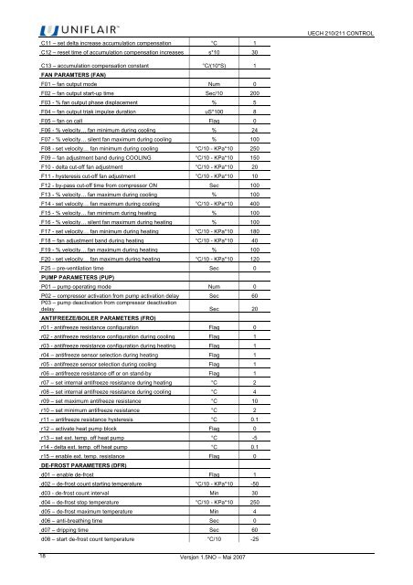
C11 – set delta increase accumulation compensation °C 1C12 – reset time of accumulation compensation increases s*10 30UECH <strong>210</strong>/211 CONTROLC13 – accumulation compensation constant °C/(10*S) 1FAN PARAMTERS (FAN)F01 – fan output mode Num 0F02 – fan output start-up time Sec/10 200F03 - % fan output phase displacement % 5F04 – fan output triak impulse duration uS*100 8F05 – fan on call Flag 0F06 - % velocity… fan minimum during cooling % 24F07 - % velocity… silent fan maximum during cooling % 100F08 - set velocity… fan minimum during cooling °C/10 - KPa*10 250F09 – fan adjustment band during COOLING °C/10 - KPa*10 150F10 - delta cut-off fan adjustment °C/10 - KPa*10 20F11 - hysteresis cut-off fan adjustment °C/10 - KPa*10 10F12 - by-pass cut-off time from compressor ON Sec 100F13 - % velocity… fan maximum during cooling % 100F14 - set velocity… fan maximum during cooling °C/10 - KPa*10 400F15 - % velocity… fan minimum during heating % 100F16 - % velocity… silent fan maximum during heating % 100F17 - set velocity… fan minimum during heating °C/10 - KPa*10 180F18 – fan adjustment band during heating °C/10 - KPa*10 40F19 - % velocity… fan maximum during heating % 100F20 - set velocity… fan maximum during heating °C/10 - KPa*10 120F25 – pre-ventilation time Sec 0PUMP PARAMETERS (PUP)P01 – pump operating mode Num 0P02 – compressor activation from pump activation delay Sec 60P03 – pump deactivation from compressor deactivationdelay Sec 20ANTIFREEZE/BOILER PARAMETERS (FRO)r01 - antifreeze resistance configuration Flag 0r02 - antifreeze resistance configuration during cooling Flag 1r03 - antifreeze resistance configuration during heating Flag 1r04 – antifreeze sensor selection during heating Flag 1r05 - antifreeze sensor selection during cooling Flag 1r06 – antifreeze resistance off or on stand-by Flag 1r07 – set internal antifreeze resistance during heating °C 2r08 – set internal antifreeze resistance during cooling °C 4r09 – set maximum antifreeze resistance °C 10r10 – set minimum antifreeze resistance °C 2r11 – antifreeze resistance hysteresis °C 0.1r12 – activate heat pump block Flag 0r13 – set ext. temp. off heat pump °C -5r14 - delta ext. temp. off heat pump °C 0.1r15 – enable ext. temp. resistance Flag 0DE-FROST PARAMETERS (DFR)d01 – enable de-frost Flag 1d02 – de-frost count starting temperature °C/10 - KPa*10 -50d03 - de-frost count interval Min 30d04 – de-frost stop temperature °C/10 - KPa*10 250d05 – de-frost maximum temperature Min 4d06 – anti-breathing time Sec 0d07 – dripping time Sec 60d08 – start de-frost count temperature °C/10 -2518Versjon <strong>1.5</strong><strong>NO</strong> – Mai 2007