1332/1432 QUICK REFERENCE - Woodcraft
1332/1432 QUICK REFERENCE - Woodcraft
1332/1432 QUICK REFERENCE - Woodcraft
- No tags were found...

You also want an ePaper? Increase the reach of your titles
YUMPU automatically turns print PDFs into web optimized ePapers that Google loves.
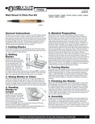
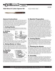
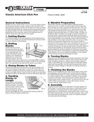
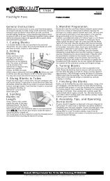
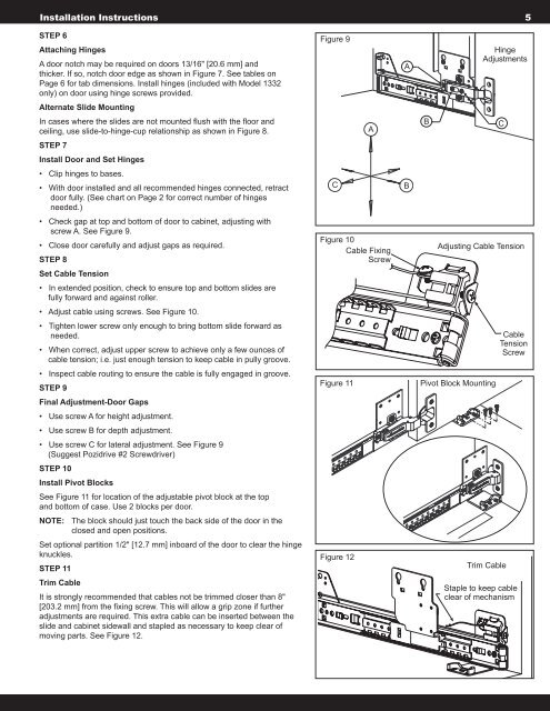
Installation Instructions 5STEP 6Attaching HingesA door notch may be required on doors 13/16" [20.6 mm] andthicker. If so, notch door edge as shown in Figure 7. See tables onPage 6 for tab dimensions. Install hinges (included with Model <strong>1332</strong>only) on door using hinge screws provided.Figure 9AHingeAdjustmentsAlternate Slide MountingIn cases where the slides are not mounted flush with the floor andceiling, use slide-to-hinge-cup relationship as shown in Figure 8.ABCSTEP 7Install Door and Set Hinges• Clip hinges to bases.• With door installed and all recommended hinges connected, retractdoor fully. (See chart on Page 2 for correct number of hingesneeded.)CB• Check gap at top and bottom of door to cabinet, adjusting withscrew A. See Figure 9.• Close door carefully and adjust gaps as required.STEP 8Figure 10Cable FixingScrewAdjusting Cable TensionSet Cable Tension• In extended position, check to ensure top and bottom slides arefully forward and against roller.• Adjust cable using screws. See Figure 10.• Tighten lower screw only enough to bring bottom slide forward asneeded.• When correct, adjust upper screw to achieve only a few ounces ofcable tension; i.e. just enough tension to keep cable in pully groove.CableTensionScrew• Inspect cable routing to ensure the cable is fully engaged in groove.STEP 9Figure 11Pivot Block MountingFinal Adjustment-Door Gaps• Use screw A for height adjustment.• Use screw B for depth adjustment.• Use screw C for lateral adjustment. See Figure 9(Suggest Pozidrive #2 Screwdriver)STEP 10Install Pivot BlocksSee Figure 11 for location of the adjustable pivot block at the topand bottom of case. Use 2 blocks per door.NOTE: The block should just touch the back side of the door in theclosed and open positions.Set optional partition 1/2" [12.7 mm] inboard of the door to clear the hingeknuckles.STEP 11Figure 12Trim CableTrim CableIt is strongly recommended that cables not be trimmed closer than 8"[203.2 mm] from the fixing screw. This will allow a grip zone if furtheradjustments are required. This extra cable can be inserted between theslide and cabinet sidewall and stapled as necessary to keep clear ofmoving parts. See Figure 12.Staple to keep cableclear of mechanism